1
f
:Save
For
This Manual
Future Reference
,SE,AR8
owner's
manuaR
NODEL NO.
113.225941
Belt and Disc Sander
with
Motor and Legs
._.-- .........................
t
Serial
Number
Model and serial numbers may
be found on the right hand side
of the base.
You should record both model
and serial number in a safe
place for future use.
LT AND DiSC
, assembly
- operating
• repair parts
FOR YO
SAFETY
READ ALL
INSTRUCTIONS
CAREFULLY
J
Sears Roebuck
Part No. SP5582
and Co., Hoffman
Estates,
IL 60179
U.S.A.
Printed
in U.S.A.
f
i FULLONE
YEAR
WARRAN
ON CRAFTSMAN
STATUONARY
TOOL
B_ _!: if this stationa_:tool fails due to a_defect in material or workmanship within one year from the
I!ii!iof
pUrChase;:C()NTACT
THE NEAREST SEARS SERVICE CENTER IN THE UNITED STATES
I:_Sears
will repair it free of charge.
Iill
This Warranty applies only while this product is in the United States.
I_iil; If this sander!s used for commercial or rental purposes, this warranty will apply for ninety
_ii: from the dateof purchase.
Iiii::This
warranty gives you specific legal rights, and you may also have other rights which vary
i!ii_ state to state.
date
and
days
from
Sears, Roebuck and Co., D/817 WA Hoffman Estates, IL. 60179
Safety instructions
For Belt and Disc Sander ........
Safety is a combination of common sense, staying alert
andknowing how your belt and disc sander works. Read
this manual to understand this sander.
Safety Signal Words
DANGER: means if the safety information is not followed
someone will be seriously injured or killed.
WARNING: means if the safety intormation is not followed someone could be seriously injured or killed.
CAUTION: means if the safety information is not followed
someone may be injured.
Before Using the Sander
mistakes
could
serious, permanent injury, do not plug the sander
I WARNING: To avoid
that
cause
in until thefollowing steps are completed,
• Completely assemble sander. See "Assembly" section.
- Learn the use and:function of the ON-OFF switch. See
"Getting to Know:You r Sander"section.
• Review and understanding of all safety instructions
and operating procedures in this manual.
- Review of the maintenance methods for this sander.
See "Maintenance" section.
Read the following WARNING
the sander:
When Installing
label found on the front of
Or Moving the Sander
Avoid dangerous environment. Use the sander in a
dry, indoor place protected from rain. Keep work area
well lighted.
Place the sander so neither the user or bystanders
forced to stand in line with the abrasive belt or disc.
To avoid burns or other tire damage, never use the
sander near flammable liquids, vapors or gasses.
To avoid injury or death from electrical shock:
• Ground the sander. This sander has an approved 3conductor cord and a 3-prong grounding type plug.
Use only 3-wire, grounded outlets rated 120 volts, 15
amperes (amps)_ The green conductor in the cord is
the grounding wire. To avoid electrocution, never connect the green wire to a live terminal
Make sure your fingers do not touch the plug's metal
prongs when plugging or unplugging the sander,
Never use this or any power sander for wet sanding.
Doing so could cause electrocution, serious injury or
worse.
To avoid injury from unexpected sander movement:
• Always unplug the sander before moving it.
• Put the sander on a firm level surface where there is
plenty of room for handling and properly supporting the
workpiece.
• Support the sander so it does not rock.
• Bolt the sander to its work surface, Use the fasteners
and method shown in "Assembly" section.
• Never stand on tool. Serious injury could occur if the
tool tips. Do not store anything above or near the too!
where anyone might stand on the tool to reach it,
To Avoid Back Injury
• Get help or use recommended casters when you need
to move the sander
• Always get help if you need to lift the sander.
•• •,
i i ¸ .... i¸¸
are
Before Each Use:
Dress for Safety:
i
Inspect your sander. Check for:
° Wear nonslip footwear.
oalignment of moving parts,
_obinding of moving parts,
o
Tie back long hair.
°
Roll tong sleeves above the elbow.
• broken or damaged parts,
o
Noise levels vary widely. To avoid possible hearing
damage, wear ear plugs or muffs when using sander
for hours at a time.
• fixtures that cause a gap larger than 1/16" between
work support and sanding surface,
° sanding belt narrower than 4 inches. Narrower belts
uncover parts that could trap your fingers.
° worn or damaged electric cords,
• stable mounting
• any other condition that may affect the way the sander
works.
°
Sanding operations are usually dusty. Wear a dust
mask along with the safety goggles.
Do not wear loose clothing, gloves, neckties or jewelry
(rings, wrist watches). They can get caught and draw
you into moving pads.
WEAR
If any part is missing, bent, or broken in any way, or any
electrical parts don't work properly, turn the sander off
and unplug the sander. Replace damaged, missing, or
failed parts before using the sander again.
Disconnect the sander to avoid injury from accidental
starting. Pdrn the switch off, unplug the sander and
remove the switch key before changing the setup, sanding disc or belt or adjusting anything.
Maintain tools with care. Keep the sander clean for best
and safest performance, Follow instructions for lubricating.
Remove wrenches from tool before turning on.
To avoid injury from jams, slips or thrown pieces:
° Use only recommended accessories. Consult this
owner's manual for recommended accessories. The
use of improper accessories may cause injury, See
"Accessory" section..
° Adjust any work support to clear the sanding surface
by no more than 1/16 of an inch. When checking clearance between the belt and work support, press the belt
flat against the metal beneath it.
• Make sure all clamps and locks are tight and no
parts have excessive play.
• Keep work area clean. Cluttered areas and benches
invite accidents. Floor must not be slippery.
Plan Ahead To Protect
Face and Ears:
Your Eyes, Hands,
Know your sander. Read and understand the owner's
manual and labels affixed to the tool. Learn its application
and limitations as well as the specific potential hazards
peculiar to this tool.
To avoid injury from accidental contact with moving
parts:
° Keep guards in place and in working order.
• Don't do layout, assembly, or setup work on the sander
while any parts are moving.
Avoid accidental starting. Make sure switch is "OFF"
before plugging sander into a power outlet.
YOUR
• Wear safety goggles. Any power sander can throw
foreign objects into the eyes_ This can cause permanent eye damage. Wear safety goggles (not glasses)
that comply with ANSI Z87.1 (shown on package).
Everyday eyeglasses have only impact resistant
lenses. They are not safety glasses. Safety goggles
are available at area stores. Glasses or goggles not in
compliance with ANSI Z87.1 could seriously hurt you
when they break.
Plan your work. Think through how you will hold and
maneuver the workpiece from start to finish.
Use the right tool. Don't force toot or attachment to do a
ob it was not designed to do.
CAUTION: This machine is not designed for heavy!
deburring
operations.
When finishing
metals,
sparks or hot fragments
could cause a fire. To
avoid this:
• Disconnect
sander.
any dust
collecting
hose
from
the
• Remove all traces of wood dust from inside the
sander,
i
I
• Remove all traces of metal dust from
sander before sanding wood again,
inside the
i
Inspect your workpiece. Make sure there are no nails
or foreign objects in the part of the workpiece to be
sanded.
Plan the way you will hold the workpiece from start to
finish. Avoid awkward operations and hand positions
where a sudden slip could cause finger or hand to move
into a sanding surface. Keep fingers away from where the
belt goes into the dust trap.
Don't overreach. Keep good footing and balance.
Keep your face and body to one side. Stay out of tine
with a possible throwback.
and Disc Sander (continued)
workpieces.
sander and workpiece.
• Never use thistool to finish pieces too small to hold by hand.
Don't force tool. It will do the job better and safer at its
designed rate. Press the workpiece against the sanding
material only hard enough to let it sand without bogging
down or binding.
Before freeing any jammed material:
° Turn switch "OFF"
• Use extra supports (tables, saw horses, blocks, etc.)
for any workpieces large enough to tip when not held
down to the table top.
= Never use another person as a substitute for a table
extension, or as additionalsupport for a workpiece that
is longer or wider that the basic sander table, or to help
feed, support orpuU the workpiece.
• Wait for all moving parts to stop.
° Unplug the sander.
• When finishing on the disc, always press the workpiece
against the "Down" side of the disc. Sanding against the
side coming up from under the table could damage the
work by making it "chatter", or tear the work from your
hands and throw it,
Before
Never leave tool running unattended,
Make workshop
child-proof.
Disconnect
master
switches Remove the yellow switch key. Store it away
from children and others not qualified to use the tool.
Lock the shop.
° Clear everything except the workpiece and related support devices off thetable before turning the sander on.
wARNING:
Don't let familiarity (gained from fre- I
quent use of your belt and disc sander) cause a
careless mistake. A careless fraction of a second is
Precautions
I
to Take When Sanding Metals
When finishing metals, sparks or hot fragments Could
cause a fire, To avoid this:
1_ Disconnect any dust Collecting hose from the sander,
Precautions
to Take When Sanding Paint
being sanded. After sanding paint, wash and clean up
before eating, drinking or smoking. Do not leave food,
drinks, or tobacco products in the work area where
dust can settle on them.
4_
3::To
not eat; drink; or :smoke in
Protect the environment when sanding paint. Use a
dust collection system if possible. Seal the work area
with plastic if necessary. Do not track paint dust outside the work area.
5. Thoroughly clean the work area upon completion of
paint sanding project. If project lasts for an extended
amount of time, clean work area often. Items such a_
sanding dust, vacuum filter bags, plastic drop cloths, etc
should be placed in a sealed container and disposed o'
properly. Clean all items exposed to sanding dust.
2. Do not allow children or pregnant women to enter the work
area Untlpaint_ sanding job is finished and al! clean up
"
......
2. Remove all traces of wood dust from inside the sander
before sanding metals.
3. Remove all traces of metal dust from inside the sander
before sanding wood again.
Sanding of lead based paint is not recommended. It is
very difficult to control the contaminated dust that could
cause lead poisoning.
It is also difficult to identify if paint contains lead. Therefore, we recommend the following precautions when
sanding all paints:
1. Protect your lungs. Always wear a dust mask or respirator at all times. Wear only dust masks that are suitable for working in lead paint sanding environments.
Ordinary painting masks do not offer this protection.
ii
the Sander:
Turn power off. Don't leave tool until it comes to a complete stop.
• Sand 0nly one workpiece at a time.
enough to cause a severe injury.
Leaving
particles_ Do
w6rk area where paint is
4
Motor Specifications
and Electrical Requirements
This machine is designed to use, and is equipped with, a
3450 RPM motor. It is wired for operation on 120 volts, 60
!Hz, alternating current.
t WARNBNG:
To avoid
fire, tool must
not be converted
to electrocution
operate on 240orvolts.
For replacement
Connecting
motor, refer to parts list in this manual.
to Power
Supply
Outlet
This machine must be grounded while in use to protect
the operator from electric shock.
In the event of a malfunction or breakdown, grounding
provides a path of least resistance for electric current to
reduce the risk of electric shock.
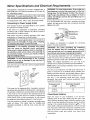
WARNING: To avoid electrocution, if the outlet you
are planning to use for this power tool is of the two
prong type, Do Not Remove Or Alter The Grounding Prong In Any Manner. Use an adapter as shown
below and always connect the grounding lug to a
known ground.
It is recommended that you have a qualified electrician
replace the two prong outlet with a properly grounded
three prong outlet.
Grounding
3-Prong
_
Lug
/
_MakeSureThisls
t_
I '-_-_11t Connected
to a
Plug power cord into a properly grounded 120V outlet
_rotected by a 1 5 amp fuse or circuit breaker.
WARNING:
To avoid
gers touch
the
jorremoving
electrocution:
terminams
of plugs
Do not let finwhen
installing
the plug to or from the outlet.
WARNING:
tf not properly
grounded,
tool can cause
an electrical
shock,
this power
particularly
when used in damp locations
close to plumbing,
an electrical
shock occurs there is the potential
a secondary
hazard, such
ing the sanding surface.
as your
hands
ff
of
contact-
WARNING: To avoid electrocution or fire, if power
cord is torn or cut, or damaged in any way, have it
replaced immediately.
'four unit is for use on 120 volts, and has a plug that looks
like the one below.
3-Prong
Plug
Adapter
An adapter, as illustrated, is available
plugs to 2-prong receptacles.
WARNING: The green
from the adapter must
nent ground such as to
box, Not all outlet boxes
for connecting
grounding lug extending
be connected to a permaa properly grounded outlet
are properly grounded.
If the grounding instructions are not completely understood or if you are not sure that your toot or outlet box is
properly grounded, check with a qualified electrician.
NOTE: The adapter illustrated is for use only if you
already have a properly grounded 2-prong receptacle.
NOTE: Make sure the proper extension cord is used and
is in good condition.
The use of any extension cord will cause some loss of
power. To keep this to a minimum and to prevent overheating and motor burnout, use the table below to determine the minimum wire size (A.W.G.) Extension cord.
Use only :3 wire extension cords that have 3-prong
grounding type plugs and a-prong receptacles which
accept the tool's plug.
Extensio
n Cord
Length
This power too! is equipped with a a-conductor cord and
grounding type plug listed by Underwriters' Laboratories.
The ground conductor has a green jacket and is attached
to the motor at one end and to the ground prong in the
attachment
plug at the other end. If repair or replacement
of the electric cord or plug is necessary,
do not connect
the equipment grounding conductor to a live terminal,
This plug requires a mating 3-conductor
grounding
outlet as shown. This outlet must be installed
grounded
according
to with all local codes and
nances,
type
and
ordi-
0-25 Ft.
26-50 Ft.
Check
Wire Sizes Required
(A.W.G.)
16
14
Motor Rotation
Place the motor on your workbench or on the floor.
Standing clear of the motor shaft, plug the motor cord
into a properly grounded outlet. Notice the rotation of the
shaft. As you look directly at the motor shaft it should be
turning in the counterclockwise direction (_'_).
tf the
motor shaft is turning counterclockwise, remove the plug
from the power outlet and continue the assembly proce_
dures. If the motor is turning clockwise, remove the ptug
from the power outlet and contact your Sears Store
immediately.
: ..........
::i:i:/i ¸¸ ::
i_:.....
: ;: i
:/::::i:i,i_
jl
_: ! : i,:i_i:::: i :: :? : :,
-::i_i_i.i.ii
i::
:
:
: i
• • •:
•
-•
installing the Abrasive Belt-. ...................................... 4
Tensioning and Tracking.: ..........................................
14
Installing Belt D ust Trap ............................................
15
._:!:i_
_:_:_:
_.i;_::_
_,,:.::.:.. 2:
i':':i:iiii:::i:::i!i:_'!:::,".
:
Installing Backstop:.. .....:...........................................
16
Getting to Know Your Belt and Disc Sander ................. 16
Safety: Instructions for Belt and Disc Sander ................ 19
i !::
Hands,
....
Before Using the Sander: ..........................................
19
3: : When 'Installing OrMoving the Sander: .................... 19
: :: BeforeEach Use:.......................................
19
Whenever Sander:iisRUnning :_i_i':i'=_i':::_i:'':i_:i_:_::'_''''--:--'4
Plan Ahead to Protect Your Eyes, Hands,
Face and Ears: .......................................................
19
Precauti0ns t0 Take When Sanding Metais;,. i.i ..,.i .i.... i._4
Basic Sander Operation ...............................................
20
Precauti0nsto Take: when Sanding
Whenever Sander is Running: .................................. 20
Motor Specifications and Electrical Requirements ......... 5
Before Leaving the Sander: ...................................... 20
Connecting to Power Supply Outlet. ............................ 5
Precautions to Take When Sanding Metals .................. 20
Table of Contents .............. i.i.._., i ..................................... 6
Precautions to Take When Sanding Paint .................... 20
Unpacking and Checking Contents ............................. 6
Surface Finishing on the Abrasive Belt ..................... 21
ToolsNeeded ....
::
..........
_.............................
:_
...............
6
End Finishing on the Abrasive Belt ........................... 21
Loose Parts...:
.....
..ii.
...................................................
6
Finishing Curved Edges on the Abrasive Belt ........... 21
U npacking ...................................................................
6
Finishing Small End Surfaces and Curved Edges
TableofLoose Parts.......................................................
7
on the Abrasive Disc .............................................
22
Assembly....
....................................................................
7
Maintenance .................................................................
22
Assembling SteelLegs ................................................
8
Motor Maintenance and Lubrication .......................... 22
When Installing
Or Moving the Sander........................
8
Lubrication
............................................
22
MountingBeltAnd DiscSander On Legset.................
9
Recommended Accessories
................................
23
Installing
V-Beltand Switch.........................................
9
Troubleshooting
.........................................
23
Installing
Sanding Disc and Dust Trap....
,..................
10
RepairParts............................................
25
InStalling
Motor,V-Beltand BeltGuard .....................
11
Motor Connections.......................................
30
On-OFF Switch.....
...........
i...
......................................
12
Installing
Work Table.................................................
14
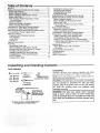
Unpacking and Checking
::
Contents
Tools Needed
Unpacking
318" Wrench
7116" Wrench
9116" Wrench
3/4" Wrench
Separate all parts from packing materials and check
each item with illustration and "Table of Loose Parts."
Medium
Screwdriver
Combination
#2 Phillips
Screwdriver
Combination
Draw Light
Line on Board
Square Must be True
Straight
""
Along this_
_I_L_
_/Board
Edge of
This Edge Must be
Perfectly Straight
314" Thick
Should be no Gap or Overlap when Square
is Flipped Over in Dotted Position
Square
NOTE: Before discarding any packing material make certain all items are accounted for.
WARNING: To avoid injury, if any parts are missing,
do not attempt to assemble the belt and disc
sander, plug in the power cord, or turn the switch
on until the missing
parts are obtained
and
installed correctly,
WARNING: For your own safety, never connect
plug to power source outlet, or insert switch key
until all assembly steps are complete and until you
have read and understood the entire owners manual.
Table of Loose Parts
Item
No.
A
B
C
D
E
F
G
H
J
K
L
M
N
O
P
Q
R
S
T
U
V
W
X
Y
Z
AA
AB
AC
AD
AE
AF
AG
AH
AJ
AK
AL
AM
AN
AO
AP
AQ
AR
AS
AT
Table of Loose Parts
Description
Qty.
V-belt, 1/2 x 41"
Fence
Dust Trap
Motor Pulley Belt Guard
Motor
Housing Disc
Cover Housing
Table, Work
Base and Table
Bag of Loose Parts
Owners Manual
Disc Sander 9"
Disc Abrasive
Bracket Mounting
Leg
Stiffener End
Stiffener Side
Channel Support
Support Motor
Bett Sanding
Bag Asm Outlet
Containing the following parts:
Bracket Switch Mtg.
Key Switch
Lockwasher 1/4
Screw Pan Hd 1/4-20 x 1/2
Screw Pan Hd #8 x 3/8
Bag of Loose Parts #509122
Pulley
Wrench
Support Belt Guard
Bracket Support
Clip S
Screw Pan Hd Ty T 10-32 x 1/2
Tie Wire
Bag of Loose Parts
Bag of Loose Parts #508419
ScrewTruss Head 1/4-20 x 1/2
Lockwasher Ext 1/4
Nut Hex 1/4-20
Foot Leveling 3/8
Nut Hex 3/8-16
Screw Hex Hd 5/16-18 x 2-1/2
Bolt Crge 5/16-18 x 3/4
Washer 11/32 x 1 !/16 x t/16
Lockwasher Ext 5/16
Nut Hex 5/16-18
1
1
1
1
1
1
1
1
1
1
1
1
1
1
4
2
2
2
1
1
1
item
No,
AU
AV
AW
AX
AY
AZ
BA
Loose
Description
Qty.
Bag of L0ose Parts #508182
Wrench Hex L 5/32
Screw Flat Hd 10-32 x 1-3/4
Screw Pan Hd Ty T 8-32 x 3/8
Washer 21/64 x 7/8 x 1/8
Screw Hex Hd 5/t6-18 x 1
Screw Pan Hd 10-32 x 9/16
Lockwasher #10
1
4
5
1
1
1
1
Parts
R
1
1
2
2
3
1
1
1
1
3
3
1
2
32
32
32
4
8
2
4
6
8
G
T
:/
C
D
L
J
H
AD AE i
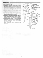
AsSembly.
As_mbiing
i.
Steei Legs _i
: ::_sid_ ;'stiffenersu_i_g |_iUr (4)1!/4 _20 t i'uss head screwsl
::::diamete_iholesaSdfingertight_n
1/4-20 nutsl
9/32: i_:ch
: :i::::::
::
i:using
:iL4 2o
3::Renlove the faUr,:::(_ii_:truss
:head screws assembled in
step 1: Place the two (2) support channels as: shown,
in position, align h01es in Supports with holes _n the
stiffeners, replace loci(washers and nuts.
4. Assembte the motor support to steel legs with 1/4-20
screws and nuts. Motor support can be mounted to
either end of stand. Tighten nuts using 7/16" wrench.
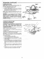
5. Install leveling feet as shown. To level leg set, loosen
nut on inside of leg and turn nut on outside to raise or
lower feet. Adjust all four levelers, and then tighten
nuts on inside of legs.
NOTE: These levelers are not intended for height
adjustment.
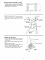
Mounting
Belt and Disc Sander
On Legset
1. Place the belt and disc sander on steef legs, position
as shown, and align the mounting holes in the base of
the belt and disc sander with those in the end stiffeners
(marked with an 'X' in the illustration).
O
I
!
i
I
I
I
O
go
I
b°
t
.....
|
i
!
HEX
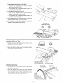
2. Mount the sander base to the end stiffener/channel
support. Use two 5/16-18 x 2-1/2" hex head screws,
flat washers, (4) external Iockwashers, and (2) hex
nuts,
HEX
_7i_ -1
HD.
SCREW
HD
LOCKWASHER
• LOCKWASHER
HEX
HEX
NUT
MOTOR
MOUNT
BRACKET
THIS SIDE
Installing
V-Belt and Switch
1. Loosen the belt table locking bolts behind the mounting bracket using a 1/2" wrench which is provided in
loose parts bag.
BELT
TABLE
LOCKING
BOLT
2. Position belt table vertically and tighten only one of the
bolts.
WRENCH
3. Place the V-belt on the pulley.
4. Attach the switch assembly to the base using the two
screws and washers packed with the switch.
5, Loosen the bolt that you tightened in step 2. Position
the belt table horizontally, and tighten both bolts.
I
MOUNTtNG
BRACKET
'
i
V-BELT
9
SWITCH
ASSEMBLY
(.PROVIDED)
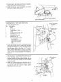
DISC DUST
TRAP
_j ii
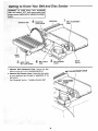
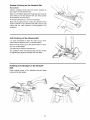
3. Find four flat head machine screw 1-3/4" long from
among the loose parts.
I_
FLAT
HEAD
1 3t4"
LONG
ii
SCREWS
1 3t4
4. Attach t_hedisc dust trap with four flat head screws 13/4" long.
5. There is a flat spot on the shaft near the end_ Rotate
the shaft so that the flat spot is facing up.
=_
i 11
i _l,,i
6. Place the disc on the shaft so that the set screw is
facing up. Position the disc so that it is approx. 1/t6"
outward from the edge of the dust trap.
_
WRENCH
DUST
TRAP
SANDING DISC
/
8. Make certain that the metal disc is free of oil and
grease then peet the backing from the 9" abrasive
disc and affix to the sanding disc,
_, '_
• .
5132 INCH
7. Insert the long end of the 5/32" setscrew wrench
through the hole in the disc housing and into the set
screw in the disc. Make sure set screw is aligned with
"flat" on shaft.
NOTE: After several hours of operation, check for
looseness of set screw and retighten,
_:_ i
•
• "
10
=
_
_
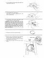
9. Removethetopleft handscrewthatyouinstalledin
step6 andloosentheotherfourscrews.
10.Installthe dusttrap coverand replacethe top lefthandscrew.Tightenallfivescrews.
TOP
DUST
Installing
Motor,
TRAP
RIGHT
HAND
V-Belt and Belt Guard
MOTOR
MOUNTING
BRACKET
1. Locate the following parts:
Qty.
SCREW
COVER
Description
LOCKWASHER
1
1
1
t
4
4
4
4
1
Motor
"L" Bracket
Pulley (approx. 2" dia.)
V-Belt
Carriage bolt, 5/16-18 x 3/4
Flat Washer, 5/16 I.D.
Lockwasher, 5/16 I.D.
Hex Nut, 5/16-18
Guard Assembly including
Guard Support
Guard Support Bracket
Self-threading Screws
Clips
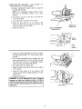
2. P]ace motor against the motor mounting bracket and
insert bolts through holes in motor base and then
through holes marked "X" in motor mounting bracket.
Do not tighten bolts at this time, The "L" bracket,
which holds the guard support, must be slid between
the motor base and the motor mounting bracket. The
motor must be loosely assembled to the bracket at
this time.
FLAT
WASHER
CARRIAGE
BOLT
5f16.18 X 3/4
MOTOR
3. Slide long leg of "L" bracket between motor base and
motor mounting bracket. Then sandwich the "L"
bracket between the guard support bracket and the
guard support and fasten together with self-threading
screws as shown.
MOTOR
MOUNTING
BRACKET
MOTOR
BASE
t
"'L'"
4. Install the 2" pulley onto the motor shaft flush with the
end of the shaft and tighten the set screw in the pulley hub with a 5/32" hex "L" wrench. Tighten against
the flat part of the motor shaft.
TWO
SET
HOLES
CLOSES
TOGETHER
SCREW
\
g
BELT
I
2"PULLEY
11
GUARD
SCREW
SELF-THREADING
1
SUPPORT
BELT
GUAHD
_\
Assembly
(continued)
....
.-
. -..
GUARD
5_ Place V_belt over machine pulley and insert the V-belt
into the _open end of the guard and out the round
.:::
:opening:i
_:
BELT
Make_sUr@:belt has not slipped off machine pul!ey from
step 3. ?Disc and: Dust Trap Installation".
6: L0cate and instatlthree clips on the guard as shown.
7. Place the belt onto the motor pulley by rotating the
pu!tey.
8_ Move the motor sideways so that the belt is in the
center of the opening in the top of the base. Visualty
tine up the pulleys and V-belt
\
9. Wedge "L" bracket under upper leg of motor base
(approximately 1/8_'):while positioning guard support
bracket around the shaft.
BELT MUST BE ON
MACHINE
10. Push downward on motor to apply tension to belt and
tighten motor bolt nuts.
11 Check guard support before tightening guard support
screws. Guard support must be centered on motor
shaft. Tighten screws
/
/I
12. Push guard into position on guard support.
t
LL
' L_
On-OFF
I I I
Switch
WARNING: Don't connect power cord to electrical
outlet in your shop until you are sure motor rotation is correct. See "Check Motor Rotation" section.
The On-Off switch has a locking feature. This feature is
intended to prevent unauthorized and possible hazardous use by children and others.
1. Insert key into switch.
NOTE: Key is made of yellow plastic.
i¸
:
i
KEY
_-_
<: :
•••
12
PULLEY
2. To turn machine on, insert finger under switch lever
and pull end of switch out.
...............
3. To turn machine OFE_PUSH
Never leave the machine
come to complete step.
,u,,,,,,,,,,
_
i
lever in.
unattended
,i i lll_
i,,Ni
until it has
i
i
4. To lock switch in OFF position.,,hold
switch
one hand...Remove
key with other hand.
,i,l,,!,l
,, ii,!ll,,ll_l
,i ,ll,i
,
,m
i !ll J,
in with
WARr, ilNG: For your own safety,
always
lock the
switch,
"OFF" when machine
is not in use, remove
key and keep it in a safe place, also in the event of
a power
failure
(all of your
lights
go out) turn
switch off, lock it and remove the key. This will prevent the machine
from starting up again when the
power comes back on,
PULL
i i,
5, Find plastic
iiiiiiiiiI
!
i
ii
I
ll!!!l
wire tie from among
llqlW
I
i ! iiiiiiiii
loose parts,
llllplll!l_l
pi
11111
II[L,IIIIIIIIIIIIIIIII
6. Route the motor cord through the leg set and plug it
into the receptacle in the side of the switch box.
7. Bring the power cord under the switch box and attach
to leg set with wire tie as shown.
, iiiii,iiiiii
ii lUll
I
I'I
II
POWER
MOTOR
8. Attach wire tie to power cord and motor cord as
shown.
CORD
1
MOTOR CORD
13
ASSembly (continued)
ABRASIVE
Installing WorkTable
DISC
NoTE_:Appiyl aCoatof paste iwax to:the work table: This
wiii:make _iia :little easier to feed the wotk_
WORK
TABLE
:;t_ Loosen the tabl'e positioning screw.
21Insert the table :support rod:in the hole in the ba:se
untilthe edge of ti_e table is approximately 1/i6" from
the abrasive disC: Tighten the screw.
NOTE:There is a second mounting hole in the base. This
is for mounting tl_e :tabie When the belt is used in a vertical position,
WARNING: To avoid trapping the work on fingers
between the table and sanding surface, the table
edge should be a maximum
1116 inch from the
sanding surface, the table should be completely
engaged on the rod.
/
/
SECOND
MOUNTING
HOLE
,
Installing
Tensioning
the Abrasive
TABLE
SUPPORT
ROD
J
TABLE
POSiTiONING
SCREW
i
p ,i ,,
Belt -
andTrack!ng
DIRECTIONAL
turn, switch _OFF_,: remove key!:and remove plug
powerTosour€el
outlet from
before
removingstart,
or
I from
WARNING:
avoid Injury
accidental
installing abrasive belt_
ABRASIVE
ARROW
IDLER
PULLEY
BELT
BELT ADJUS_tENT
KNOB
NOTE: Two types of belts may be used,
On the smooth side of the abrasive belt you will see a
!'direCtional arrow."
.EVER
DRIVE
Lap Splice: The abrasive belt must run in direction of this
arrow so that the splice does not come apart:
Butt Splice: The arrow points in both directions or identifies no arrows, this indicates the user may position the
belt in either direction.
1:::Pdsh tension |eVer to rear position:
2. Turn bett adjustment knob counterclockwise.
3. Appty light pressure to the idler pulley so the pulley
moves to rigfit_ :_:
4. Place the abrasive belt over the idler and drive pulleys with the-directional arrow pointing as shown.
Make sure the abrasive belt is centered on both pul_
teys.
5. Position tension lever in forward position. When the
idler pulley is moved outward, it puts tension on the
belt.
6. Standing to the side of the machine, push the belt by
hand to check if belt is moving either left or right.
14
IN REAR
POSITION
7, If the
abrasive belt moves to the right:
a. Turn the belt adjustment knob clockwise slightly,
until the belt recenters itself.
b. The abrasive belt is tracking properly when it is
centered on the drive pulley.
8. If the abrasive belt moves to the left:
ABRASIVE
DISC
a. Turn the belt adjustment knob counterclockwise
slightly until the belt recenters itself,
b. The abrasive belt is tracking properly when it is
centered on the drive pulley.
9, Turn machine on and off several times to observe
tracking. Repeat steps 7 and 8 as needed.
10. Turn machine on and adjust tracking, if needed, by
turning the belt adjusting knob slightly.
PUSH BELT IN
DIRECTION OF DISC
BELT
MOVING
TO RIGHT
DRIVE
PULLEY
BELT
ADJUSTING
KNOB
RIGHT
LEFT
i
installing
i
i
ii iiii
Belt Dust Trap
1. Find one 10-32 x 9/16" pan head screw and a lockwasher among the loose parts.
2. Attach the dust trap. Make sure the top edge is below
the surface of the abrasive belt.
PAN HEAD SCREW
AND LOCKWASHER
Installing
Backstop
BELT
BACKSTOP
1. Find one 5/16 x 1" hex head bolt and one flat washer
among the loose parts,
LOCK
2. Place the washer on the bolt, and screw it halfway
into the mounting hole. Place the backstop into position and tighten the bolt. When removing the backstop, loosen the bolt but do not remove it.
15
SCREW
DUST
TRAP
BACKSTOP
iiiiiiiiiii
_Getting to Know Your Belt and Disc Sander
start, turn switch "OFF" and remove plug from
power
sourceTooutlet
adjustWARNING::
avoidbefore
Injurymaking
from any
accidentalJi
ments-
ABRASIVE
DISC
4
BACKSTOP
LOCK SCREW
BACKSTOP
1
BELT ADJUSTMENT
KNOB
\
WORK
TAB LE
WORK TABLE
TILT LOCK SCREW
[
i
ii
6
BELT TENSION
BELTTABLE
STOP
ii i
LEVER
,
•
1. Abrasive Belt Adjustment Knob, Causes the idler
pulley to move in or o ut for tracking adjustment.
2. Abrasive Belt Tension Lever. Causes the idler pulley
to move backward and fox,yard for adjustm ent of the
belt tension.
See"Assembly"section-
IDLER
PULLEY
BELT ADJUSTMENT
"Installing Abrasive Belt"
\
16
KNOB
3.Work
Table Tilt Lock Screw. Locks the table, it is
locked using the 1/2' wrench supplied.
a. Using a combination square, check the angle of
the table with the disc.
NOTE: The combination square must be "true".
See start of "Assembly" section on for check
method.
b. tf the table is not 90° to the disc...toosen tilt lock
screw and tilt table.
c. Loosen the lock nut using a 7/16" wrench.
d. Screw the stop screw in or out, using a 3/8"
wrench so that when the table touches the top
screw, the table is 90 ° to the disc.
\
e. Tighten the lock nut.
TABLE
1/!6"
FROM
DISC
TABLE POSITIONING
LOCK SCREW
L_
STOP
SCREW
_i tfJ
LOCK
TILT
LOCK
NUT
SCREW
i
UI_
I
I'11111
i
ii II
J
J
_Llllll!l
IIIII![L
f. Loosen the table positioning lock screw...position
the table approximately 1/16" away from the abrasive disc.
g. Tilt the table downward but don't tighten the lock
screw, and position it as close to the disc as possible. Using the head of a combination square,
check the angle of the table with the disc.
h. tf the table is not 45° with the disc:
i. Raise the table and loosen the lock nut using a
7/16" wrench.
j. Screw the stop screw in or out, using a 3/8"
wrench so that when the tabte touches it, it is 45 °
with the disc.
k. Tighten the lock nut.
WARNING: To avoid trapping the work or fingers
between the table and sanding surface, the table
must be repositioned on the rod to maintain a maximum 1/16 inch space between the table and sanding surface,
STOP SCR EW
17
mill iii
,
ii ij _II
to Know
Your Belt and: Disc Sander
4. Backstop:Lock scre_w. Locks the backstop in place, tt
is:iocked using:the ii/2, wrench:Supplied:
(continued)
BACKSTOP
LOCK
SCR
EW
BACKSTOP
\
\
5. Belt Table Locking
tion.
Bolts. Lock the belt table in posi-
To adjust to vertical position:
a. Remove the backstop.
b. Loosen the two belt table locking bolts using the
1/2" wrench, supplied with your machine.
c. Position belt table vertically and tighten the two
bolts:
6. AbrasiveBeit
Table Stop. Can be adjusted so that
the abrasive belt table is level when in a horizontal
position:.
a. Loosen the lock nut using a 3/4'! wrench.
b.Place a level on tl_e abrasive belt table and using
a 3/4" wrench, screw the stop bolt in orout until the
table is level,
BELT
TABLE
LOCKING
STOP
LOCK
Safety Instructions
serious, permanent injury, do not plug the sander
I WARNING: To avoid mistakes
that could cause !
in until the following steps are completed.
• Completely assemble the sander. See "Assembly" section.
• Learn the use and function of the ON-OFF switch. See
"Getting to Know Your Belt and Disc Sander" section.
° Review and understanding of all safety instructions
and operating procedures in this manual.
• Review of the maintenance methods for this sander.
See "Maintenance" section.
Or Moving
NUT
for Belt and Disc Sander
Before Using the Sander:
When Installing
BOLT
the Sander:
Avoid dangerous environment. Use the sander in a dry,
indoor place protectedfrom rain. Keep work area well lighted.
Place the sander so neither the user or bystanders are
forced to stand in line with the abrasive belt or disc.
To avoid burns or other fire damage,
sander near flammable liquids, vapors or
To avoid injury or death from electrical
'GrOund the sander. This sander has
never use the
gasses.
shock:
an approved 3-
conductor cord and a 3-prong grounding type plug.
Use only 3-wire, grounded outlets rated 120 volts, 15
amperes (amps). The green conductor in the cord is
the grounding wire. To avoid electrocution, Never connect the green wire to a live terminal.
° Make sure your fingers do not touch the plug's metal
prongs when plugging or unplugging the sander.
o Never use this or any power sander for wet sanding. Doing
so could cause electrocution, serious injury or worse.
To avoid injury from unexpected sander movement:
° Always unplug the sander before moving it.
• Put the sander on a firm level surface where there is
plenty of room for handling and properly supporting
the workpiece.
o Support the sander so it does not rock.
o Bolt the sander to its work surface. Use the fasteners
and method shown in "Assembly" section,
• Never stand on tool, Serious injury could occur if the
tool tips. Do not store anything above or near the tool
where anyone might stand on the tool to reach them.
18
To Avoid Back Injury
o Get help or use recommended casters when you need
to move the sander
o Always get help if you need to lift the sander.
Before
Each Use:
Inspect your sander. Check for:
o alignment of moving parts,
• binding of moving parts,
o broken or damaged pads,
o worn or damaged electric cords,
stable mounting
• any other condition that may affect the way the sander
works,
If any part is missing, bent, or broken in any way, or any
electrical parts don't work properly, turn the sander off
and unplug the sander. Replace damaged, missing, or
failed parts before using the sander again.
Disconnect the sander to avoid injury from accidental
starting, Turn the switch off, unplug the sander and
remove the switch key before changing the setup or
sanding belt and disc.
Maintain tools with care. Keep the sander clean for the
best and safest performance.
Remove wrenches from tool before turning on.
To avoid injury from jams, slips or thrown pieces:
° Use only recommended
accessories.
Consult this
owneCs manual for recommended accessories. The
use of improper accessories may cause injury. See
"Accessory" section.
• Adjust any work support to clear the sanding surface
by no more than 1/16 of an inch. When checking clearance between the belt and work support, press the belt
flat against the metal beneath it.
• Make sure all clamps and locks are tight and no
parts have excessive play.
• Keep work area clean. Cluttered areas and benches
invite accidents. Floor must net be slippery.
Plan Ahead to Protect Your Eyes, Hands,
Face and Ears:
Dress for Safety:
• Wear nonslip footwear.
, Tie back long hair.
• Roll long sleeves above the elbow.
o Noise levels vary widely, To avoid possible hearing
damage, wear ear plugs or muffs when using sander
for hours at a time.
• Sanding operations are usually dusty. Wear a dust
mask along with the safety goggles.
• Do not wear loose clothing, gloves, neckties or jewelry
(rings, wrist watches). They can get caught and draw
you into moving parts.
o Wear safety goggles. Any power sander can throw
foreign objects into the eyes. This can cause permanent eye damage. Wear safety goggles (not glasses)
that comply with ANSI Z87.1 (shown on package).
Everyday eyeglasses have only impact resistant
lenses. They are not safety glasses. Safety goggles
are available at area stores. Glasses or goggles not in
compliance with ANSI Z87.1 could seriously hurt you
when they break.
Know your sander. Read and understand the owner's
manual and labels affixed to the tool. Learn its application and limitations as well as the specific potential hazards peculiar to this tool.
To avoid injury from accidental contact with moving parts:
• Keep guards in place and in working order.
° Don't do layout, assembly, or setup work on the sander
while any parts are moving.
Avoid accidental starting. Make sure switch is "OFF"
before plugging sander into a power outlet.
Plan your work, Think through how you will hold and
maneuver the workpiece from start to finish.
Use the right tool, Don't force tool or attachment to do a
job it was not designed to do.
Inspect your workpiece make sure there are no nails or
foreign objects in the part of the workpiece to be sanded.
Plan the way you wilt hold the workpiece from start
to finish. Avoid awkward operations and hand positions
where a sudden slip could cause finger or hand to move
into a sanding surface. Keep fingers away from where the
bolt goes into the dust trap.
Don't overreach. Keep good tooting and balance.
Keep your face and body to one side, out of line with a
possible throwback.
19
iii
i
Whenever
+:Makesurethereis no debrisbetweenthe workplace
andits supports.
• When sandir+g irregularly shaped workpieces, plan
your work support So it will not slip and be pulied from
your hands.
• Use extra caution with large, very small or awkward
wo rkpieces.
• Never use Ibis toot to finish pieces too small to hold by hand.
• Use extra supports (tables, saw horses, blocks, etc.)
for any workpieces large enough to tip when not held
down to the tabletop.
° Never use another person as a substitute for a table
extension, or as additional support for a workpiece that
is longer or wider that the basic sander table, orto help
feed; support or pull the workpiece.
• Clear everything except the workpiece and related support devices off the table before turning the sander on+
• When finishing on the disc, always press the workpiece
against the "Down'_side of the disc. Sanding against the
side coming up from under the table could damage the
work by making it "chatter". or tear the work from your
hands and throw it.
• Sand only one workpiece at a time.
i
L =
Sander
_,,
,
,
II
.
is Running:
Before starting your work, watch the sander while it runs.
If it makes an unfamiliar noise or vibrates a lot, stop
immediately. Turn the sander off. Unplug the sander. Do
not restart until finding and correcting the problem,
Make sure the sanding disc turns counterclockwise,
belore using the sander.
Keep children away. Keep all visitors a safe distance
from the sander. Make sure bystanders are clear of the
sander and workpiece.
Don't force tool. It will do the job better and safer at its
designed rate. Press the workpiece against the sanding
material only hard enough to let it sand without bogging
down or binding.
Before freeing any jammed material:
° Turn switch "OFF".
° Wait for al! moving parts to stop.
• Unplug the sander.
Before
Leaving
the Sander:
Turn power off, Don't leave tool until it comes to a complete stop.
Never leave tool running unattended.
Make workshop child-proof. Lock the shop. Disconnect
master switches. Remove the yellow switch key. Store it
away from children and others not qualified to use the
t0ol.
WARNING: Don't let familiarity
(gained from frequent use of your belt and disc sander) cause a
careless mistake. A careless fraction of a second is
enough to cause a severe injury.
Precautions
to Take When Sanding Metals
When finishing metals, sparks or hot fragments
cause a fire. To avoid this:
could
1. Disconnect any dust collecting hose lrom the sander:
Precautions
2, Remove all traces of wood dust from inside the sander
before sanding metalsl
3. Remove all traces of metal dust from inside the sander
before sanding wood again.
to Take When Sanding Paint
........
Sanding of lead based paint is not recommended. It is
very difficult to control the contaminated dust that could
cause lead poisoning.
It is also difficult to identify whether or not paint contains
lead. Therefore we recommend the following precautions
when sanding all paints:
3. To prevent ingesting contaminated paint particles: Do
not eat, drink, or smoke in a work area where paint is
being sanded. After sanding paint, wash and clean up
before eating, drinking or smoking. Do not leave food,
drinks, or tobacco products in the work area where
dust can settle on them.
1. Protect your lungs. Wear a dust mask or respirator at
all times. Wear only dust masks that are suitable for
working in lead paint sanding environments. Ordinary
painting masks do not offer this protection.
4. Protect the environment when sanding paint. Use a
dust collection system if possible+ Seal the work area
with plastic if necessary, Do not track paint dust outside the work area,
2+Do not altlowchildren or pregnant women to enterthe work
area until paint sanding job is finished and all clean up
completed:
5. Thoroughly clean the work area upon completion of
paint sanding project. If project lasts for an extended
amount of time, clean work area often, items such as
sanding dust, vacuum filter bags, plastic drop cloths, etc.
should be placed in a sealed container and disposed ol
properly. Clean all items exposed to sanding dust.
2O
,ii
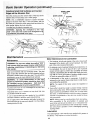
Surface
Finishing
on the Abrasive
Belt
\
Flat surfaces
\
Hold the workpiece firmly with both hands, keepir_g fingers away from the abrasive belt.
Keep the end butted against the backstop and move the
work evenly across the abrasive bell Use extra caution
when finishing very thin pieces.
For finishing long pieces, remove the backstop.
Apply only enough pressure to allow the abrasive belt to
remove material. If the abrasive belt stalls and the belt
pulleys slip, too, much pressure is being applied to the
workpiece
End Finishing
on the Abrasive
Belt
It is more convenient to finish the ends of long workpieces with the abrasive belt in a vertical position.
Move the work evenly across the abrasive belt. For accuracy, use a miter gauge.
lii
The table may be tilted for beveled work.
See "Getting to Know Your Belt and Disc Sander" section
for adjusting the abrasive belt table and work table.
Finishing Curved Edges on the Abrasive
Belt
Finish outside curves on the abrasive belt and inside
curves on the idler pulley.
21
t
der Operation
the Abrasive
(continued)
|1
!L
J
DOWN SIDE
(LEFT)
Disc
/
Move thework acroSs the "Down Side" of the face of the
abrasive diSc_ Foraccuracy; use a miter gauge.
MITER GAUGE /
NOTE: Use a combination square to square the miter
•gauge tothe face of the disc: If it is not square, pull out
the index pin, loosen the miter gauge knob and move the
miter gauge, tighten the knob securely.
The table may be tilted for beveled work
SQUARE
\
\
I WARNING: Applying the workpiece
to the "Up 1
I Side" of the disc first could cause workpiece to fly
I up (kickback) and result in an injury.
I
Maintenance
i i
nl,,i,
i
nn ,i
t ill|Hi
Maintenance
IWARNING_
For:your own safety, turn switch "OFF" I
1 and'remove plug from power: source outlet before I
I adjusting, maintaining, or lubricating your belt and i
disc sander,
l
Keep _our machineand
your workshop clean. The dust
traps around the abrasive disc and the abrasive belt are
designed to deflect most of the fine dust. They should be
connected to a vac for most eflicient dust removal.
{WARNING:
To avoid electrocution or fire, any
Jrepairs to electrical systems should be done only
I by qualified service technicians.
Unit must be
I reassembled exactly to factory specifications.
If powercord is worn or cut, or damaged in any way, have
it replaced immediately.
Frequently blow out or vacuum out any dust that may
accumulate inside the motor.
A coat of automobile-type wax applied to the worktable
will make it easier to feed the work while finishing.
'
uul
i
.......................
_, ii,
Motor Maintenance
ii
,,
=H,,
u,,,,,=,l,
and Lubrication
1. The bearings, in both end shields of the motor, have bee/
lubricated at the factory with correct lubricant. No othei
part of the motor required lubrication.
2. Re-lubricate motor bearings following the instructions on
the nameplate. Be sure to wipe oft dirt or grit if present
around oil hole caps to prevent any possibility of foreign
material contaminating the oit wicks that supply the bearings with oi!. Use a good grade of medium weight mineral
oil, such as automobile engine oil SAE 20.
3. If disassembly of the motor is necessary, it should be
returned to your nearest Sears retail store in order to prevent voiding the guarantee.
NOTE: The speed of this motor cannot be regulated or
changed.
4. Every effort should be made to prevent foreign material
from entering the motor. When operated under conditions
likely to permit accumulations of dust, dirt, or waste within
the motor, a visual inspection should be made at frequent
intervals. Accumulations of dry dust can usuaIly be blown
out successfully,
Do not apply wax to the abrasive belt table because the
belt could pick up the wax and deposit it on the pulleys,
causing the bet! to slip.
NOTE: Motors used on wood-working tools are particularly susceptible to the accumulation of sawdust and
wood chips and should be blown out or "vacuumed" frequently to prevent interference with normal motor ventilation and proper operation of the centrifugally-operate_
starting switch.
Lubrication
The ball bearings in this machine are packed with grease at
the factory, They require no further lubrication,
22
Recommended
Accessories
..............
Sears Recommends the following accessories:
Do not use any accessory unless you have received and
read complete instructions for its use.
Oat, No.
item
,,
Caster Set
Miter Gauge
Pressure-Sensitive Cement
Abrasive Belts and Discs
Steel Legs
Power Tool Know How Handbook
h
See your nearest Sears store for other accessories.
'...................
;,,,,,,
9-22222, 9-22221
9-29929
See Catalog
See Catalog
9-22236
9-291 17
WARNING: Use only accessories recommended for ]
this sander. Using other accessories may be dangerous.
/
,._ou...es.oo..nu
............
.......
Motor
I
I WARNING:
your
own safety, turn switch "OFF" and remove plug from power source outlet before trou- I
bleshooting For
your
sander.
NOTE: Motors used on wood-working tools are particularly susceptible to the accumulation of sawdust and wood chips
and should be blown out or "vacuumed" frequently to prevent interference with normal motor ventilation and proper
operation of the starting switch.
Trouble
.....
, ...............
,
....
Probable Cause
, ...............
,,,
,,i
.........................., ..........................
,......
Remedy
, ..........
.....
,
......
"
,...........
,,,_
Excessive Noise
1. Motor
1. Have motor checked by qualified service technician,
Repair service is available at your nearest Sears
retail store,
Motor failed to
develop full power.
NOTE:
Low Voltage:
(Power output of
motor decreases rapidly with decrease in
voltage at motor terminals. For example,
a reduction of 10% in
voltage causes a
reduction of 19% in
maximum power output of which the motor
is capable, and a
reduction of 20% in
voltage causes a
reduction of 36% in
maximum power output,)
1. Circuit overloaded with
lights.
2. Undersize wires or circuit too
long,
3. General overloading of
power company facilities.
Do not use other appliances or motors on same circuit when using the saw,
2, Increase wire sizes, or reduce length of wiring, See
"Electrical Requirements" section.
3. Request a voltage check from the power company.
Motor starts slowly or
fails to come to full
speed
1. Low voltage.
2. Windings burned out or open.
3. Starting switch not operating.
1. Request voltage check from power company,
2, Have motor repaired or replaced,
3. Have switch replaced.
Motor overheats
1. Motor overloaded,
1. Feed work slower into belt or disc.
2. Clean out sawdust to provide normal air circulation
through motor, See "Maintenance" section.
2. Improper cooling. (Air circulation restricted through motor
due to sawdust, accumulating.
23
.
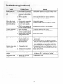
ootmg (con nued)
::
HH_L
II
'
=' = r
:Starting switchJn
1_ Burned sWitCh_ontactS(dUel _ 1. Have switch replaced and request a voltage check
motOrwiit'notoper
- : :i t0 extendedf_old-in periods
=fromthe power company.
ii:ate_
i _::_i :_i: caused by 10wlinevoltagei
: ]
a
,,,o,
oc,,vo.
oo; •.a::w:.
o:::::::::::::::::::
:
tions.
Motor stalts (resulting in blown fuses or
.:tripped circuit breakers)
Frequent opening of
fuses or circuit
[
L
_
Motor will not run
.....
I
1. Starting switch not operating.
2. Voltage too low to permit
motor to reach operating
speed.
3. Fuses or circuit breakers do
not have sufficient capacity.
1. Have switch replaced.
2. Request voltage check from the power company.
1. Motor overloaded.
2. Fuses or circuit breakers do
not have sufficient capacity.
1. Feed work slower into belt or disc.
2, install proper size fuses or circuit breakers.
3. Starting switch not operating
(motor does not reach
.... speed)
3. Have switch replaced,
1, Defective On-off switch.
Defective switch cord.
Defective switch box.
1. Replace defective parts before using belt and disc
sander again.
2. Consult Sears Service. Any attempt to repair this
3. Install proper size fuses or circuit breakers.
2. Burned out motor,
.....
motor may create a hazard unless repair service is
done by a qualified service technician. Repair service is available at your nearest Sears retail store.
.....
Machine slows down
when sanding
:
[:
....
....
Abrasive
pulleys
•
belt tuns off
_
....
•
• ..i i
•
:
2. Applying too much pressure
to workpiece
2. Ease up on pressure.
1. Not tracking properly,
=
.....
:•
:•
•'
_i¸
_•
,
1. abrasive disc or belt is
_
glazed with sap.
:•
1. Adjust tracking, See "Assembly" section, "Installing
the abrasive Belt - Tensioning and Tracking".
..
,
,
1. Replace disc or belt.
•
i i_.:_i
_ _i/.._
ii i _
_.... _i_i _ _i,!ii_
.....
1. Decrease belt tension, see "Maintenance" section,
"Removing Pulley Cover and Installing Timing Belt.
.
Wood burns while
sanding
i
1. Timing belt too tighL
:
:
:
•
_i__ _ _
24
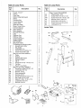
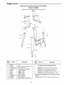
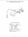
Repair Parts ...........................
Parts List for Craftsman
Begt and Disc Sander
Model 113.225941
A]ways order by Part Number--Not
by Key Number
Figure 1
3
4
4
7
6
3
3 je
f
LI
f
2
f
Key
No.
Part No.
1
2
3
4
5
6
7
8
9
10
11
820040
60314
STD541025
STD551225
68060
68059
62615
68061
STD541237
803835-1
508419
Description
No. I
Leg
J- Screw, Truss Hd. 1/4-20 x 1/2
"1_ Nut, Hex 1/4-20
"1- Lockwasher, 1/4 External
Channel, Support
Stiffener, Side
Stiffener, End
Support, Motor
"1- Nut, Hex 3/8-16
t Foot, Leveling
Bag of Loose Parts (Not Ills.)
25
Part No.
Description
Hardware for mounting toot & motor
!
--
STD523125 1"1-Screw, Hex Hd. 5/16_2-1/2
--
STD541231 "1- Nut, Hex Jam 5/16 x 18
STD551031 *1-Washer, 11/32xlli16xli16
STD551131 I "1 Lockwasher, External 5/16
STD532507 "I" Bolt, Carriage 5/16q/x 3/4
1-These items all contained in Loose Parts Bag, Part No.
508419
* Standard Hardware Item - May be purchased tocally
"6
E
i
i
£
o
dd
_5
I
_D
o
£
i
i
i
S
@
6
z
o_
E
, Z
E_
c_
o
z
mz_
II1 >.
i_ -_
o
E_
X
.o
o
K
,m
O
_1
11.
4---
6
Z
.
i •
co c,,I
o o4
,,r- c,
o
(N
DID
27
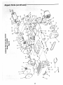
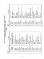
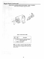
Parts List for Craftsman
Belt and Disc Sander
A_ways order by Part Number--Not
- iViodei 113.225941
by Key Number
Figure 3 - Motor Part No. 68072
KeyPart
No.
No.
1
60306
2
3
64088
64258
NOTE:
hazard
nician.
Service
it
....-
Description
I
Screwl 8-32 x3/8, Thread Cutting,
Slotted, Serrated Head
Cover, Terminal
Cord w/Plug
Any attempt to repair this motor may create a
unless repair is done by a qualified service techRepair service is available at your nearest Sears
Center.
28
Parts List for Craftsman
Belt and Disc Sander - Model
Always order by Part Number--Not
113.225941
by Key Number
6
Figure 4 - On/Off Power Outlet 60382
Key
No.
1
2
3
4
5
6
Part No.
60382
60375
60378
9-22255
60374
60376
448007
Description
* On/Off Power Outlet
Cord, Molded
Housing, Switch
1" Key, Switch
Switch, Locking
Cover, Switch
Screw, Pan Hd. No. 6 x 3/4
• Does not include Key No. 3 - order separately if
required.
1 Stock Item - May be secured through the Hardware
Department of most Sears store.
29
-::WARNiNG:i.For::your
i;:_eps _
€ompleted_
outlet until all assembly
own safety, never connect 1
located on side of
motor;Using a flat blade screwdriverl
•
:
:,,,,, _
:
! _WARNING: To i avoid electrocution,
I anything but the ground wire
Ithe green screw.
never connect I
(colored
green)to
I
Black Motor
Cord Lead On
#1
2. Remove green screw and insert through round metal
terminal on the end of the green wire of motor cord:
3. Reinsert green screw in threaded hole that it was
removed from and tighten securely.
4. Connect terminal end of black wire to terminal #1 on
the motor. Push terminal firmly until seated.
5. Connect terminal end of white wire to terminal #4 on
the motor. Push terminal firmly until seated.
Green Motor
Cord Lead
Under Green
;crew
6, Close motor connector box being sure that motor cord
is seated in lower strain relief groove and tighten box
cover screws.
Vlotor Cord in
Strain Relief
Groove
"White Motor
Cord Lead On
Terminal #4
Z
Motor Cord Connections
i:iii_•_•i
i!z¸_!:i•:i•¸•
30
Notes
............................
3_
• /
ELT AND DISC
SANDER
For the repair or replacement parts you need
Call 7 am - 7 pm, 7 days a week
t -800-366=PART
MODEL NO,
113o225941
(1-801)-366-7278)
For in-home major brand repair service
Call 24 hours a day, 7 days a week
t -800=4,-REPA|R
(1-800-473-7247)
The model number of your Belt
and Disc Sander will be found
on a plate attached to the right
hand side of the base.
For the location of a
Sears Repair Service Center in your area
Call 24 hours a day, 7 days a week
t -800-488-1222
When requesting service or
ordering parts, always provide
the following information:
- Product Type
• Model Number
lIIII_
For information on purchasing a Sears
Maintenance Agreement or to inquire
about an existing Agreement
Call 9 am - 5 pro, Monday-Saturday
t -800-827-6655
• Part Number
• Part Description
SEARS
America's
Repair
, ii
Sears Roebuck
Part No. SP5582
and Co., Hoffman
SP5582-5
Specia tis ts
i
ii i i i
Estates,
i ill
i ,,,,,i
IL. 60179
H
H ,,,,,,
i
U.S.A.
Printed in U.S,A, 4t97