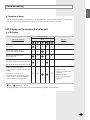
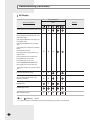
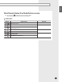
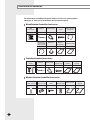
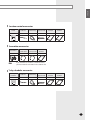
1
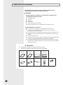
Safety Precautions Keep this installation manual together with the user’s manual in a handy place so that you can find it whenever you need to see it after reading this manual thoroughly. Make sure to read the following safety precautions carefully before installation. Make sure to observe the cautions specified in this manual. Conduct a test run of the unit after installation and then explain all system functions to the owner. The indications and meanings are as shown below. WARNING This indicates the possibility of serious injury or death. The unit should be installed in accordance with the National Electrical regulations. Ensure that the national safety code requirements have been followed for the main supply circuit. Ensure that a properly sized and connected ground wire is in place. E-2 Check if the voltage and the frequency of the main power supply are those required for the unit to be installed and check the connection. Make sure that properly sized disconnecting and safety switches are installed. Do not attempt to repair, move, modify or reinstall the unit on your own. Make sure that these installations are carried out by qualified personnel to avoid electric shock or fire. Use the unit on a single outlet circuit. Do not share the power outlet with other appliances. Obtain the consent by a qualified installer before connecting the unit to the power supply system. ENGLISH WARNING This indicates the possibility of serious injury or death. Installation must be carried out by a qualified installer. Installers are required to read the general information carefully for safety. Do not put the unit near dangerous substances to prevent fire, explosion or injury and do not expose the unit to direct sunlight. Do not install the unit by yourself (owners). Incorrect installation of the unit could cause injury due to fire, electric shock and water leakage or from the unit falling. Consult a dealer or a qualified installer. Install the unit in a place where it is strong enough to hold the product weight. When installed in place where it is not strong enough to withhold the product weight, the unit could fall and cause injury. Use the specified wires to connect the indoor and outdoor units securely and attach the wires firmly to the terminal block connecting sections so that the pressure is not applied to the sections. Inappropriate connection and fixing could cause fire. Avoid the use of an extension cord and do not share the power outlet with other appliances. Incomplete connection, defective insulation or exceeding the permissible current may cause electric shock or fire. Make sure that the refrigerant gas does not leak after completing the installation. If the refrigerant gas of the indoor unit leaks and comes into contact with the fan heater, space heater or stove, harmful substances will be generated. Perform the installation securely referring to the installation manual. Incomplete installation could cause personal injury due to fire, electric shock and water leakage or from the unit falling. Attach the electrical cover to the indoor and outdoor unit securely. If not, it could result in fire or electric shock due to dust or water. Make sure to use the part provided or specified parts for the installation work. The use of defective parts could cause an injury or leakage of water due to a fire, an electric shock, the unit falling, etc. Make sure to turn off the main power when setting up the indoor unit electrical circuit or power cords. There is a risk of electric shock. The units must be installed according to distances declared, in order to permit accessibility from each side, either to guarantee correct operation of maintenance or repairing products. The unit’s parts must be reachable and removable completely under safety condition (for people or things) E-3 CAUTION This indicates the possibility of serious injury or damage to environments when operated incorrectly. Check the unit for damage that may have taken place during transportation and do not install or use damaged equipment. All of the manufacturing and packaging material used for your new appliance are compatible with the environment and can be recycled. Dispose of the packaging material in accordance with the local requirements. This product is an air conditioning system and contains a coolant that must be recovered and disposed of in an appropriate way by qualified personnel. At the end of the life cycle, take it to a proper recycling or disposal center or return it to the dealer so that it can be disposed correctly. E-4 Grounding the unit. Fasten a flare nut with a Do not install the unit in a The air conditioner must be Do not connect the ground to a gas pipe, water pipe, lightning rod or telephone grounding. Defective grounding could cause electric shock. place where it is exposed to inflammable gas leakage. There is a risk of explosion. Install a ground leakage breaker depending on the installation place (where it is humid). If not, it may cause electric shock. Perform the drainage/piping work securely according to the installation manual. If not, water could drop from the unit and household goods could get wet and damaged. torque wrench as specified in this installation manual. When fastened too tight, a flare nut may break after a long period of time and cause refrigerant leakage. installed according to the national electrical regulations. The maximum input power & current is measured according to the IEC standard and the input power & current is measured according to the ISO and EN14511standard. ENGLISH Contents Preparation for installation . . . . . . . . . . . . . . . . . . . . . . . . . . . . . . . . . . . . . . . . . . . . . . . . . . . . . . . . . . . . Deciding on where to install the indoor unit . . . . . . . . . . . . . . . . . . . . . . . . . . . . . . . . . . . . . . . . . . Indoor unit installation . . . . . . . . . . . . . . . . . . . . . . . . . . . . . . . . . . . . . . . . . . . . . . . . . . . . . . . . . . . . . . . . Purging the unit . . . . . . . . . . . . . . . . . . . . . . . . . . . . . . . . . . . . . . . . . . . . . . . . . . . . . . . . . . . . . . . . . . . . . . Connecting the refrigerant pipe . . . . . . . . . . . . . . . . . . . . . . . . . . . . . . . . . . . . . . . . . . . . . . . . . . . . . . Cutting/Flaring the pipes . . . . . . . . . . . . . . . . . . . . . . . . . . . . . . . . . . . . . . . . . . . . . . . . . . . . . . . . . . . . . Performing leak test & insulation . . . . . . . . . . . . . . . . . . . . . . . . . . . . . . . . . . . . . . . . . . . . . . . . . . . . . Drain hose installation . . . . . . . . . . . . . . . . . . . . . . . . . . . . . . . . . . . . . . . . . . . . . . . . . . . . . . . . . . . . . . . . Connecting the connection cord . . . . . . . . . . . . . . . . . . . . . . . . . . . . . . . . . . . . . . . . . . . . . . . . . . . . . Assigning address to indoor unit . . . . . . . . . . . . . . . . . . . . . . . . . . . . . . . . . . . . . . . . . . . . . . . . . . . . . Troubleshooting . . . . . . . . . . . . . . . . . . . . . . . . . . . . . . . . . . . . . . . . . . . . . . . . . . . . . . . . . . . . . . . . . . . . . . Additional accessories . . . . . . . . . . . . . . . . . . . . . . . . . . . . . . . . . . . . . . . . . . . . . . . . . . . . . . . . . . . . . . . . 6 7 9 10 11 12 13 14 15 16 17 20 E-5 Preparation for installation When deciding on the location of the air conditioner with the owner, the following restrictions must be taken into account. General Do NOT install the air conditioner in a location where it will come into contact with the following elements: Combustible gases Saline air Machine oil Sulphide gas Special environmental conditions If you must install the unit in such conditions, first consult your dealer. Avoid installing the air conditioner: In areas where it is exposed to direct sunlight. Close to heat sources. In damp areas or locations where it could come into contact with water (for example rooms used for laundry) In areas where curtains and furniture could affect the supply and discharge of air. Without leaving the required minimum space around the unit (as shown in the drawing). In scarcely ventilated areas. On surfaces that are unable to support the weight of the unit without deforming, breaking or causing vibrations during the use of the air conditioner. In a position that does not enable the condensate drainage pipe to be correctly installed (at the end of the installation. It is always essential to check the efficiency of the drainage system.) Accessories The following accessories are supplied with the indoor unit. The type and quantity may differ depending on the specifications. E-6 User’s manual Installation manual Insulation drain Insulation cover pipe Insulation pipe Insulation drain pipe Cable-tie Wireless remote control Battery ENGLISH Deciding on where to install the indoor unit Indoor unit As an underceiling indoor unit, this unit has to be installed as floor type only. There must be no obstacles near the air inlet and outlet. Select a convenient location that permits the air to reach every corner of the area to be cooled. Pre-plan for easy and short routing of the refrigerant tubing and wiring to the outdoor unit. There should be no flammable gas, alkaline, substances present in the air. Maintain sufficient clearance around the indoor unit. Make sure that the water dripping from the drain hose runs away correctly and safely. Do not install the unit where it will be exposed to direct sunlight. Space requirements for indoor unit �� �� � ��� �� ��� ��� � ��� ��� � �� ��� ��� ��� � ��� � CAUTION The units must be installed according to distances declared, in order to permit accessibility from each side, either to guarantee correct operation of maintenance or repairing products. The unit’s parts must be reachable and removable completely under safety condition (for people or things). This model can be installed with no side space. But it is recommended installing like above. E-7 Deciding on where to install the indoor unit (Continued) Drawing of the indoor unit 199 620 4 2 75 115 16 65 30 48 720 96 1 104 147 18 161 68 28 3 89 Description No. Name MHFJEA 1 2 3 4 Liquid pipe connection Gas pipe connection Drain pipe connection Power supply connection ø6.35 ø9.52 ID: ø12 ; OD: ø18 - Dimension And Weight MHFJEA Net Dimension Indoor Unit mm 720*620*199 Net Weight Indoor Unit kg 15.2 Maximum installation height: up to 3.6m Condensate discharge pump(built-in): Max. 750mm Length of pipes and difference in height: see the outdoor unit installation manual Vacuum and refrigerant charge: see the outdoor unit installation manual E-8 Indoor unit installation 1 When you install the indoor with side-pipe connection, please make space more than 300mm from the wall at the pipe connection direction. ENGLISH It is recommended to install the refnet joint before installing the indoor unit 300m m 300m m 2 When you install the indoor at the inclined floor, please lean the set toward the drain hose and pipe connection to prevent water overflowing. Position of drain Position of drain Screw Hole The body front should be opened to connect pipes. Please release the 4 screws of body front and then pull it out from the top of the set. Screw Hole 3 E-9 Indoor unit installation(Continue) 75mm 4 Making a hole on the wall (Please make a hole as below guide) 5 The pipes & cable should be go through the bottom back hole. 6 Please remove EPS & Uretane when you install. Ø60~65mm Drain hose Less than 70mm Inside room Outside room Purging the unit Liquid refrigerant port Gas refrigerant port From factory the unit is supplied and set with a pre-charge of nitrogen gas (insert gas). Therefore, all insert gas must be purged before connecting the assembly piping. Make sure all the nitrogen gas is purged out before installing the unit. If not, do not install the unit because leftover nitrogen could cause internal leakage. Unscrew the pinch pipe at the end of each refrigerant pipe. Result: Note The designs and shape are subject to change according to the model. E-10 All inert gas escapes from the indoor unit. To prevent dirt or foreign objects from getting into the pipes during installation, do NOT remove the pinch pipe completely until you are ready to connect the piping. ENGLISH Connecting the refrigerant pipe There are two refrigerant pipes of different diameters: 1 A smaller one for the liquid refrigerant A larger one for the gas refrigerant The thickness of tube should not be less than 1.0mm. The inside of copper tube must be clean & has no dust. Refrigerant oil Remove the pinch pipe on the pipes and connect the assembly pipes to each pipe, tightening the nuts, first manually and then with a torque wrench, a spanner applying the following torque. Outer Diameter 6.35 mm (1/4”) 9.52 mm (3/8”) 12.70 mm (1/2”) 15.88 mm (5/8”) 19.05 mm (3/4”) Note Torque (N•m) 18 42 55 65 100 Spanner Flare nut Union If the pipes must be shortened refer to page 10. 2 Must use insulator which is thick enough to cover the refrigerant tube to protect the condensate water on the outside of pipe falling onto the floor and the efficiency of the unit will be better. 3 Cut off any excess foam insulation. 4 Be sure that there must be no crack or wave on the bended area. 5 It would be necessary to double the insulation thickness(10mm or more) to prevent condensation even on the insulator when if the installed area is warm and humid. 6 Do not use joints or extensions for the pipes that connect the indoor and outdoor unit. The only permitted connections are those for which the units are designed. CAUTION Torque wrench Connect the indoor and outdoor units using pipes with flared connections(not supplied). For the lines, use insulated, unwelded, degreased and deoxidized copper pipe,(Cu DHP type to ISO1337), suitable for operating pressures of at least 4200kPa and for a burst pressure of at least 20700kPa. Copper pipe for hydro-sanitary applications is completely unsuitable. Spring pipe CAUTION Use the bender which have a minimum bending radius when you bend the pipe. Be careful so that the pipes is bended one time only. Piping will be very difficult if you repeat the bending more than twice. If you bend the pipe by using spring Bending radius should be more than 100mm so that pipe is not distorted. For sizing and limits (height difference, line length, max. bends, refrigerant charge, etc.) see the outdoor unit installation manual. All refrigerant connection must be accessible, in order to permit either unit maintenance or removing it completely. E-11 Cutting/Flaring the pipes 1 Make sure that you have the required tools available. (pipe cutter, reamer, flaring tool and pipe holder). 2 If you wish to shorten the pipes, cut it with a pipe cutter, taking care to ensure that the cut edge remains at a 90° angle with the side of the pipe. Refer to the illustrations below for examples of edges cut correctly and incorrectly. Oblique Rough 3 To prevent any gas from leaking out, remove all burrs at the cut edge of the pipe, using a reamer. 4 Slide a flare nut on to the pipe and modify the flare. Outer diameter (D) 6.35 mm (1/4”) 9.52 mm (3/8”) 12.70 mm (1/2”) 15.88 mm (5/8”) 19.05 mm (3/4”) 5 6 Depth (A) 1.3mm 1.8mm 2.0mm 2.2mm 2.2mm Check that the flaring is correct, referring to the illustrations below for examples of incorrect flaring. Inclined Valve Burr Damaged Surface Cracked Uneven Thickness Align the pipes and tighten the flare nuts first manually and then with a torque wrench, applying the following torque. Flare nut Valve cap Pressure port cap Valve needle Pressure port N•m Wrench(mm) N•m Wrench(mm) N•m Wrench(mm) N•m Wrench(mm) N•m Wrench(mm) 1/4" 3/8" 1/2" 5/8" 3/4" 17 22 26 29 36 18 42 55 65 100 23 23 29 29 38 20 20 40 40 40 18 18 18 18 18 16~18 16~18 16~18 16~18 16~18 Allen(hex.) 5 9 Allen(hex.) 5 9 Allen(hex.) 5 13 Allen(hex.) 5 13 Allen(hex.) 5 13 - 0.34 0.34 0.34 0.34 0.34 CAUTION In case of welding the pipe, you must weld with nitrogen gas blowing. E-12 ENGLISH Performing leak test & insulation Leak test LEAK TEST WITH NITROGEN (before opening valves) In order to detect basic refrigerant leaks, before recreating the vacuum and recirculating the R-410A, it’s responsable of installer to pressurize the whole system with nitrogen (using a cylinder with pressure reducer) at a pressure above 30 bar (gauge). LEAK TEST WITH R-410A (after opening valves) Before opening valves, discharge all the nitrogen into the system and create vacuum. After opening valves check leaks using a leak detector for refrigerant R-410A. CAUTION Discharge all the nitrogen to create a vacuum and charge the system. Insulation Once you have checked that there are no leaks in the system, you can insulate the piping and hose. 1 No gap To avoid condensation problems, place T13.0 or thicker Acrylonitrile Butadien Rubber separately around each refrigerant pipe. Note Always make the seam of pipes face upwards. NBR(T13.0 or thicker) 2 Wind insulating tape around the pipes and drain hose avoiding to compress the insulation too much. 3 Finish wrapping insulating tape around the rest of the pipes leading to the outdoor unit. 4 The pipes and electrical cables connecting the indoor unit with the outdoor unit must be fixed to the wall with suitable ducts. Indoor unit Be sure to overlap the insulation Insulation cover pipe CAUTION Must fit tightly against body without any gap. CAUTION All refrigerant connection must be accessible, in order to permit either unit maintenance or removing it completely. E-13 Drain hose installation When installing the drain hose for the indoor unit, check if condensation draining is adequate. When passing the drain hose through the 65-mm hole drilled in the wall, check the following: 5cm less Ditch The hose must NOT slant upwards. The end of the drain hose must NOT be placed under water. Do NOT bend the hose in different directions. Keep a clearance of at least 5cm between the end of the hose and the ground. Do NOT place the end of the drain hose in a hollow. Drain hose installation Shield Drain hose Extension drain hose (No default resource) 1 If necessary, connect the 2-meter extension drain hose to the drain hose. 2 If you use the extension drain hose, insulate the inside of the extension drain hose with a shield. 3 Fit the drain hose into 1 of 2 drain hose holes, then fix the end of the drain hose tightly with a clamp. If you don’t use the other drain hose hole, block it with a rubber stopper. 4 Pass the drain hose under the refrigerant pipe, keeping the drain hose tight. 5 Pass the drain hose through the hole in the wall. Check if it slants downwards as seen in the picture. The hose will be fixed permanently into position after finishing the installation and the gas leak test; refer to page 11 for further details. 6-Ways to connect Drain Hose and Pipe Knock out � E-14 Connecting the connection cord ENGLISH CAUTION Always remember to connect the refrigerant pipes before performing the electric connections. When disconnecting the system, always disconnect the electric cables before disconnecting the refrigerant pipes. Always remember to connect the air conditioner to the grounding system before performing the electric connections. The indoor unit is powered by the outdoor unit by means of a H07 RN-F connection cable (or a more power model), with insulation in synthetic rubber and jacket in polychloroprene(neoprene), in accordance with the requirements of standard EN 60335-2-40. 1 Remove the screw on the electrical component box and remove the cover plate. 2 Route the connection cord through the side of the indoor unit and connect the cable to terminals; refer to the figure below. 3 Route the other end of the cable to the outdoor unit through the ceiling & the hole on the wall. 4 Reassemble the electrical component box cover, carefully tightening the screw. Wiring diagram 1(L) 2(N) F1 F2 Earth Wire Indoor unit Outdoor unit Earth Wire Between Indoor and Outdoor Connection Cord Specifications Indoor Power Supply Indoor Communication Cable Connection Wire 3G,1.0mm2 or more 2G, 0.75mm2 or more For connection cord, use the grade H07RN-F or H05RN-F materials. E-15 Assigning address to indoor unit 1 Before installing the indoor unit, assign an address to the indoor unit according to the air conditioning system plan. 2 The address of the indoor unit is assigned by adjusting MAIN(SW02) and RMC(SW04) rotary switches. 23 78 901 456 SW05 SW06 SW07 SW04 RMC SW02 MAIN 3 It is required to set the RMC address if you install the wired remote control and/or the centralized control. 4 If you install optional accessories such as the wired remote control, centralized control, etc. see an appropriate installation manual. 5 If an optional accessory is not installed, you do not have to set the RMC address. However, adjust K1 and K2 switches of the SW05 DIP switch to "ON" position in this case. 6 Set the MAIN address by adjusting the rotary switch(SW02) from 0 to 9. Each indoor unit connected to the same outdoor unit must have different address. The MAIN address is for communication between the indoor unit and the outdoor unit. Therefore,you must set it to operate the air conditioner properly. 23 78 901 456 SW04 RMC E-16 SW02 MAIN SW05 SW06 SW07 ENGLISH Troubleshooting Detection of errors If an error occurs during the operation, one or more LED flickers and the operation is stopped except the LED. If you re-operate the air conditioner, it operates normally at first, then detect an error again. LED Display on the receiver & display unit LED Display LED lamp display White Abnormal conditions X Power reset Error of temperature sensor in the indoor unit (Open/Short) X Error of heat exchanger sensor in the indoor unit X Remarks X X X X X X X X Error of the outdoor temperature sensor X Error of the condensor temperature sensor X X Error of the discharge temperature sensor 1. Indoor and outdoor unit time out 2. Abnormal data reception more than 60 packet 3. Indoor unit is not connected 4. Communication error between the outdoor unit Main-Inverter Micom(After 1 minute of Main-Inverter detection) On Flickering X X X 1. Indoor unit error (Display is unrelated with operation) 2. Outdoor unit error (Display is unrelated with operation) X Off If you turn off the air conditioner when the LED is flickering, the LED is also turned off. E-17 Troubleshooting (Continued) LED Display LED lamp display White Abnormal conditions Remarks X X X X Detection of the float switch X X X Error of setting option switches for optional accessories X X X Communication error between indoor units [Self diagnosis]Power voltage detection between indoor and outdoor unit communication cable [Self diagnosis]Outdoor unit refrigerant leakage(Gas leak) [Self diagnosis]Outdoor fan restriction error [Inverter]Inverter compressor operation failure [Inverter] DC peak error [Inverter]DC Link voltage 150V or less, 410V or more X [Inverter] Compressor rotation error [Inverter]Electric current error [Inverter]DC Link sensor error [Inverter]EEPROM READ/WRITE error [Inverter]Inverter zerocrossing error Setting the outdoor unit capacity option error X EEPROM error X EEPROM option error X MPI no feedback Error On Flickering X X X X Off If you turn off the air conditioner when the LED is flickering, the LED is also turned off. E-18 ENGLISH Wired Remote Display Error Mode(Option resource) If an error occurs, is displayed on the wired remote control. If you would like to see an error code, press the Test button. Indoor unit Display Explanation Remark No feedback error Indoor unit Communication Error Indoor/Outdoor unit Communication Time Out Error 60 Packet Over data Indoor Temp. Sensor (Open/Short Error) Indoor Unit Eva in Sensor (Open/Short Error) EEPROM ERROR EEPROM Option setting error E-19 Additional accessories For information on additional options and accessories,see either product catalogue or accessories installation and operation manual. Wired Remote Controller Accessories M4x16 tapped Indoor unit power screw drawing cable Wired remote controller Cable-tie Cable clamp 1 2 5 7 1 Wire joint Owner’s instructions Installation manual 1 1 1 Communication cable of the wired remote controller 1 Centralized control accessories Centralized control Cable-tie Cable clamp M4x16 tapped screw User's manual Installation manual 1 2 5 7 1 1 Wireless Remote Controller Accessories Wireless remote controller 1 E-20 Remote Batteries for M4x12 tapped User's manual control holder remote controller screw 2 2 1 1 Installation manual 1 ENGLISH Function control accessories Function control Cable-tie Cable clamp M4x16 tapped screw User's manual Installation manual 1 2 6 7 1 1 Transmitter accessories Transmitter 1 Note Transmitter Transmitter power cable communication cable 1 1 Installation manual 1 If you would like to install the centralized control, you must install the transmitter in the outdoor unit. 7-day scheduler accessories 7-day scheduler Cable-tie Cable clamp M4x16 tapped screw User's manual Installation manual 1 2 2 4 1 1 E-21 ENGLISH INSTALLATION MANUAL EΛΛHNIKA (Cooling and Heating) DEUTSCH Free Joint Multi Air Conditioner PORTUGUÊS ITALIANO FRANÇAIS ESPAÑOL MHFJEA Series E S F I P D G DB98-29317A(1)