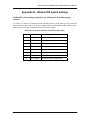
1
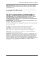
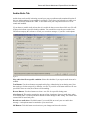
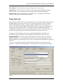
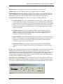
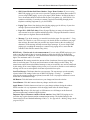
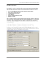
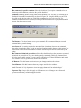
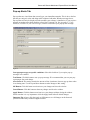
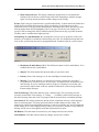
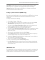
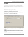
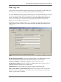
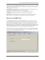
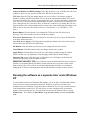
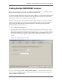
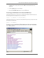
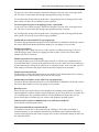
Sensorsoft Remote Watchman™ Express Remote Watchman™ Client User Manual Software Version 5.0 Manual P/N 071-0066 Rev 9 January 6, 2012 Copyright © 1998-2012 Sensorsoft Corporation, All rights reserved. Sensorsoft and Remote Watchman are trademarks of Sensorsoft Corporation. Table of Contents About This Manual ............................................................................................................4 Glossary of Acronyms........................................................................................................4 Overview .............................................................................................................................5 System Requirements ........................................................................................................6 Installation Procedure .......................................................................................................7 Removal Procedure............................................................................................................7 Starting the Software.........................................................................................................8 Connecting to your first Sensorsoft device (SSD) ...........................................................8 Configuring the Software ..................................................................................................9 Sensor Tab ................................................................................................................................9 Audio Alerts Tab ....................................................................................................................12 Pager Alerts Tab .....................................................................................................................13 Run Command Tab.................................................................................................................16 Pop-up Alerts Tab...................................................................................................................18 E-mail Alerts Tab (RWMC Only) ..........................................................................................19 Setting up an E-mail Event (RWMC Only)............................................................................21 Log Files Tab..........................................................................................................................22 HTML Page Tab.....................................................................................................................24 Web Server Tab (RWMC Only).............................................................................................25 Running the software as a separate User under Windows XP ....................................26 Creating Multiple RWMX/RWMC Instances...............................................................27 Removing Selected RWMX/RWMC Instances .............................................................28 Viewing Statistics .............................................................................................................29 Remotely Viewing HTML Pages and Log Files (RWMC only)...................................31 Configuring the Sensorsoft Web Server .................................................................................31 Setting up the HTML Page .....................................................................................................31 Connecting your Web Browser to the Sensorsoft Web Server...............................................32 Frequently Asked Questions ...........................................................................................33 Troubleshooting Error Messages ...................................................................................34 Getting Help .....................................................................................................................37 Technical Support...................................................................................................................37 30 Day Money Back Guarantee..............................................................................................37 Returns....................................................................................................................................37 Appendix A – Pager Tutorial..........................................................................................38 Appendix B – Modem DIP switch settings ....................................................................40 Appendix C – Using Dollar ($) Variables in your messages ........................................41 Appendix D – Making changes to the program INI file ...............................................42 Sensorsoft Remote Watchman Express/Client User Manual About This Manual This document contains information about installing, configuring, using and troubleshooting Sensorsoft Remote Watchman Express and Remote Watchman Client Version 5.0. When other sections of this manual are referenced, Italics are used. The term sensor, Sensorsoft device and its acronym SSD refer to devices that use the Sensorsoft Device Protocol. When the phrases “the software” or “the program” are used, it refers to both Remote Watchman Express and Remote Watchman Client. Please note some portions of this manual may only apply to RWMC. Glossary of Acronyms CRC – Cyclic Redundancy Check – error checking scheme DTMF – Dual Tone Multi-Frequency – this is the technical terminology for Touch Tone™ DIP – Dual Inline Package IANA – Internet Assigned Numbers Authority ISP – Internet Service Provider PSP – Paging Service Provider RWMX – Remote Watchman Express software RWMC – Remote Watchman Client software RWMS – Remote Watchman Device Server software SMS – Short Message Service – defines any alphanumeric message that is sent to a paging device. SMTP – Simple Mail Transfer Protocol – used to send e-mail messages over a TCP network SSD – SensorSoft Device – a device that incorporates the Sensorsoft Device Protocol TAP – Telocator Alpha-Paging Protocol – used to send alphanumeric messages to a pager 4 Sensorsoft Remote Watchman Express/Client User Manual Overview Remote Watchman Express (RWMX) and Remote Watchman Client (RWMC) are software that allow you to control and monitor remote environments using your Windows based computer and various Sensorsoft protocol devices (SSD). The software is capable of logging sensor data to a text-delimited time/date stamped file that may be exported to third party software for analysis or graphing. The software can work with SSD’s that are attached to COM ports. RWMC has the added feature of being TCP/IP capable. This allows RWMC to connect to remote SSD’s over TCP/IP networks, send e-mail alerts, and share sensor readings and log files using its integrated web server. The following types of alerts can be issued when sensor readings breach user set thresholds or return back to a normal state: Audio Alerts Run Command (launch command lines or scripts) Pop-up Alerts Pager Alerts E-mail Alerts (RWMC only) The software also has the ability to issue scheduled commands or messages at a specific time and day of the week. For the purpose of this manual, we use the ST6105 Sensorsoft Thermometer to demonstrate how this software interacts with an SSD. While this software supports all SSDs, each specific device may interact somewhat differently than this manual may depict. In this case refer to the manual associated with the specific SSD you are using. 5 Sensorsoft Remote Watchman Express/Client User Manual System Requirements Operating System: Microsoft Windows 95/98/NT/2000/2003/XP/Vista/2008/7 CPU: Intel Pentium II 300 MHz processor or equivalent RAM: 8 MB per sensor instance Hard disk space: Installation Program – minimum 25 MB, Libraries – 8 MB, Sensor Instance – 1 MB each (not including log files) CD-ROM drive Modem required if paging is used. Supported modems are U.S. Robotics Sportster, Practical Peripherals, Hayes and Hayes compatible Web Browser: (Microsoft Internet Explorer is recommended) Sound Card (16 bit) and speakers, if audio alerts are required TCP/IP LAN or Internet connection (RWMC only) TCP/IP Services (RWMC only) SMTP compliant mail server, if e-mail alerts are required (RWMC only) 6 Sensorsoft Remote Watchman Express/Client User Manual Installation Procedure Before you begin installation, please note that you need to be logged into the target computer as an administrator. 1. Log into the target computer (where you want to install the software) as the Windows administrator. 2. Close any applications that might be running. 3. Place the Remote Watchman CD into the target computer’s CD-ROM drive. 4. The autorun sequence of the CD should open a web page in your default web browser. In the event that this does not occur, manually open the file named Version Index.html, which can be found in the root directory of the CD-ROM. From this web page you will find out what versions of software are on the CD-ROM. 5. Follow the hyperlink under Remote Watchman Express or Remote Watchman Client, depending on which product license you purchased. This will lead you to a file named setup.exe. Run this file and wait for on screen instructions. 6. You must indicate that you accept the license agreement before installing. PLEASE READ THIS AGREEMENT CAREFULLY. 7. Enter the required serial number (license key) as printed on the front of your Remote Watchman CD jewel case. Use all CAPS. Removal Procedure During removal of the software, you will need to be logged into the target computer as the administrator. Once the removal is completed, you may wish to delete the log files, HTML pages and instance directories that have been left behind. To determine the location of these files, before removing the software from your system, please refer to Log Files Tab. The log files can consume several megabytes of hard drive space, after extended use of this software, and it is therefore beneficial to remove the files if they are not going to be used in the future. 1. 2. 3. 4. Log into the target computer (where the software is installed) as the Windows administrator. Close any applications that might be running. From the Windows Start button choose Settings – Control Panel – Add/Remove Programs. Select Sensorsoft Remote Watchman Express or Sensorsoft Remote Watchman Client from the list and click the Remove button. If during the removal procedure any dialog boxes ask whether to remove a shared system file such as an .OCX or .DLL, choose to Keep or Do not remove the file. This situation may happen if the same system file is shared by a number of applications. If you accidentally choose to remove one of these files, you will have to re-install the application that uses that shared system file. 7 Sensorsoft Remote Watchman Express/Client User Manual Starting the Software To start the software click on the Windows Start button and select Programs – Remote Watchman Express or Remote Watchman Client. For this example, we will configure Remote Watchman Client with an ST6105 Sensorsoft Thermometer. Once the software is launched, the following window should appear. The master instance (indicated by the letter M) has control over creating and removing other instances (see Creating Multiple RWMX/RWMC Instances). Measure/Update Button Figure 1 Connecting to your first Sensorsoft device (SSD) 1. Determine where your SSD is connected: a) If the SSD is connected directly to a COM port on the back of your computer, determine the COM port number. b) If the SSD is connected directly to a COM port on the back of your computer and is being shared by Remote Watchman Device Server software (RWMS), determine the IP address or domain name of your computer, and the TCP port number that RWMS is using to share the SSD. The default TCP port number used by RWMS is usually 6100 or 6101. c) If the SSD is connected to a remote computer or terminal/device server and is accessible on your TCP/IP network - determine the remote IP address or domain name and TCP port number where the SSD is connected. 2. Click on the word Menu as shown in Figure 1 above. Choose Settings from the drop-down menu and the Sensor Tab will be displayed. 3. If you have RWMX or RWMC and your SSD is connected as in a) above, select COM Port (RS232) from the Port Type drop down list. Then select the COM port number in the COM Port drop down list. 4. If you have RWMC and your SSD is connected as in b) or c) above, select TCP Momentary from the Port Type drop down list. In the IP/DNS Name:Port Number box, type the IP address and TCP port number using a colon to separate the two. Press the <Enter> key to save this entry to the list. 8 Sensorsoft Remote Watchman Express/Client User Manual 5. Click the measure/update button to the right of the display as shown in Figure 1 and note that the software will attempt to connect to the SSD. Progress messages will be displayed (CONNECTING, SENDING, DISCOVER). 6. Click on the “Connect to sensor on program start” checkbox and press the Apply or OK button to save your settings. Configuring the Software Sensor Tab From this tab you can specify the various settings related to sensor communications and alert thresholds for your monitored location. In the screen shot below a Sensorsoft Thermometer is attached to a Lantronix device server in a remote server room. Figure 2 Location or Description: This field contains the name of the location where the SSD is located or a description. This field is enabled for change in the Master instance and is disabled for all other instances. 9 Sensorsoft Remote Watchman Express/Client User Manual Variable Selected: This is where you select the variable to be monitored. Most SSD’s will only have one variable. Unit of Measure: If you have an SSD that displays scalar (integer or floating point measurements), then the Unit of Measure drop down will be active. In some cases, if more than one Unit of Measure is available, the user can control which Unit of Measure is used. (e.g. Celsius vs. Fahrenheit) Boolean States: If you have an SSD that displays Boolean conditions (two states only), then the States/Conditions field will be completed when the SSD is discovered. Device Type: This box will always show ‘Sensorsoft Device (SSD)’. No other devices are currently supported. Port Type: The only option available in RWMX is ‘COM Port (RS232)’. RWMC offers two additional options; ‘TCP Momentary’, and ‘TCP Continuous’. TCP Momentary allows your SSD to be accessed by multiple clients. Using ‘TCP Continuous’ locks-up the SSD so that only one client can access it; other subsequent clients will get a rejection message. IP/DNS Name:Port Address: (RWMC only) Enter the address of the remote device server or computer that is sharing the SSD on your network, and the TCP port number assigned to the SSD on the remote device server or computer using the following format: <IP/DNS name>:<TCP port number>. Click the Apply or OK button to save your entry in the list. By pressing the <Enter> key after each new entry you can quickly add new entries to the list, however you must still click the Apply or OK button to save it in the list. To remove an entry from the list, select the entry to be removed and press the <Delete> key, then select another existing entry and Click the Apply or OK button to save your changes. When the SSD is connected to a Lantronix Device Server, the port number can be between 3001-30xx. The xx is dependent on the physical port number where the SSD is connected on the Lantronix Device Server. If the SSD is connected to a Windows computer running the RWMS software, the TCP port number is determined by the setting used in this software. The default TCP port number used by the RWMS software is usually 6100 or 6101. COM Port: This indicates the serial port to which your SSD is connected. A list of COM ports is available, ranging from COM 1 to 16. However, not all of these ports may be available on your system. Update reading every: This setting controls how frequently the SSD’s reading is updated. Use the up and down buttons to make changes to the setting. In TCP Momentary, the lowest reading rate is restricted to reduce multi-client interference. Max retries on timeout or CRC errors: This is the number of times the software will attempt to send commands to the SSD after a time-out or CRC error has occurred. Use the up and down buttons to make changes to the setting. Response time-out: This is the amount of time (in seconds) that the software will wait for a command-response from the SSD before considering it as a time-out condition. If you are connected to an SSD over a network where there are long distances (thousands of miles) or propagation delays (satellite link), increase this setting for best results. Use the up and down buttons to make changes to the setting. Re-attempt after connection/time-out failure: This setting controls how much delay (in seconds) is used before the software will attempt to reconnect to the SSD, after a connection or time-out failure. Use the up and down buttons to make changes to the setting. In TCP Momentary, the lowest setting is restricted to prevent multi-client interference. 10 Sensorsoft Remote Watchman Express/Client User Manual Beep on TCP Connection: (RWMC only) Select this checkbox if you would like RWMC to beep when it makes a connection with the SSD. Please note that a sound card or PC speaker is required for this to work. Connect to sensor on program start: Select this checkbox if you would like the software to automatically connect to the SSD when the software is started. Otherwise, you will need to click the measure/update button to start the monitoring. Global Enable of Alerting check box: Select this checkbox to enable all alerting and deselect it to disable all alerting. Scalar Thresholds – Critical Low, Warning Low, Warning High, Critical High: These settings indicate the minimum and maximum acceptable scalar (integer or floating point) measurements for the SSD you are monitoring before an alert state is reached. The alert will trigger when the reading is at or below the Critical/Warning Low or at or above the Critical/Warning High. If the SSD does not have a scalar (integer or floating-point) measurement, you should refer to Boolean Alert State. Boolean Alert State: This setting controls which Boolean state condition should trigger an alert. (e.g. WET or DRY, PWR_FAIL or PWR_OK) Current Sensor ID: When the first reading of the SSD is taken, the software will automatically complete the following fields (see Fig. 2): Model, Description, Class, Number of Vars, Firmware Version and Manufacturer. OK Button: Click this button to activate/save your changes and close the window. Cancel Button: Click this button to abort any changes and close the window. Apply Button: Click this button to activate/save your changes without closing the window. Please note that it is very important to click the Apply button after all desired changes. Important Tip: Always click the Apply or OK button to save all changes on the form and prevent an unnecessary technical support incident. Important Tip: The SensorStartDelay variable in the rwmx/rwmc.ini file can be used to add a delay before the first command is sent to the SSD. This delay can be useful in preventing errors when the SSD is being powered up. This delay can be disabled by setting SensorStartDelay=0 for Lantronix Device Servers, since they power the SSD at all times. Cyclades Terminal Servers require this variable to be set to at least 1-2 seconds since they only power the SSD when the TCP connection is active. The default value of SensorStartDelay is 1 second. See Appendix D – Making changes to the program INI file. 11 Sensorsoft Remote Watchman Express/Client User Manual Audio Alerts Tab Audio alerts can be useful in alerting you and your peers to problems at the monitored location if they are within earshot of your computer’s speaker(s). These alerts can be heard even while your screen is locked in Windows NT/2000. To use audio alerts your computer must have a 16 bit sound card installed. If you choose to enable Audio Alerts, then it is on this tab that you can select which .wav file will be played to indicate a specific alerting condition. You can choose to use the pre-recorded .wav files that accompany the software or record your own alert messages, if you have a microphone. Figure 3 Play audio alert file on specific condition: Select this checkbox if you require audio alerts to be enabled. Test Buttons: Use the test buttons to sample audio clips, without being in an alerting state. Note that each type of alert can specify a different .wav file. If you click a test button where no file was specified or does not exist, the software will do nothing. Browse Buttons: Use these buttons to select a .wav file for a specific alerting state. Alert Interval: This setting controls the amount of time (in minutes) between audio alerts when in an alerting state. Use the up and down buttons to make changes to this setting. The normal state restored alert is issued only once. Record new audio alert: Click this button if you would like to record your own audio alert message. A microphone must be attached to your sound card. OK Button: Click this button to activate/save your changes and close the window. 12 Sensorsoft Remote Watchman Express/Client User Manual Cancel Button: Click this button to abort any changes and close the window. Apply Button: Click this button to activate/save your changes without closing the window. Please note that it is very important to click the Apply button after all desired changes. Important Tip: Always click the Apply or OK button to save all changes on the form and prevent an unnecessary technical support incident. Pager Alerts Tab Pager alerts are useful if you need to inform people that are not near the monitored location, about potential problems. Pager alerts can be sent to a variety of paging devices such as dedicated numeric and alphanumeric pagers, e-mail pagers and cell phones with text messaging. This software uses industry standard SMS-TAP or DTMF to deliver messages to your paging device. Sending page messages requires an AT compatible modem to be installed/attached to the computer that is running this software. If you require pager alerts then it is here that you set the modem type and port, pager type and alert specifications for each type of alert event. The pager specific settings below have to be completed individually for each alert event. Remember to Apply your changes after completing the information for each alert event. Important Note: This software must be able to open the COM port where your modem is installed and therefore is not compatible with TAPI devices. If you have RAS (Remote Access Service) enabled on your modem port, please refer to your Windows documentation or support to turn it off. If you are new to paging or the Remote Watchman line of products, you may wish to read Appendix A – Pager Tutorial and Appendix B – Modem DIP switch settings before continuing. Figure 4 13 Sensorsoft Remote Watchman Express/Client User Manual Modem Type: Select the type of modem attached or installed on your computer. Modem Port: Select the COM port where your modem is attached or installed. Lock modem port: Select this checkbox if this is the only SSD you are monitoring. This will improve reliability and prevent other applications on your computer from using the modem. By deselect this option other instances of this software will be able to use pager alerts too. Advanced SMS-TAP Settings: This frame is not enabled for DTMF paging type. Connect Time-out: We do not recommend that you make changes to this setting unless you are getting connect time-out messages, because the remote modem is taking a long period of time to answer the line. If you increase this setting, you will also need to make changes to the S7 setting of the applicable modem setup file. The S7 setting should be 2 seconds less than this connect time-out setting. Use the up and down buttons to make changes to the setting. Response Time-out: We do not recommend changes to this setting unless you are getting no-response errors during pages. In the case of slower paging providers, you might be required to set the value of the Response Time-out to a longer period (in seconds) for successful message delivery. Retries on failure: If this software detects that a page message was not delivered due to an error, it will attempt to re-send the message the number of times you indicate here. If the message is not delivered successfully during the set number of retries, then the software will stop trying to send the message. Delay before fail retry: This setting controls the length of time in seconds that the software will wait after a paging message fails before attempting to send the message again. Events: Each event type required must be specified individually. A check mark in the Enable box beside the Event indicates that a message will be sent for that event. Ensure that you have selected the correct event type before completing the following details. Please note that you must click the Apply button before highlighting a new event type, in order for your changes to be saved. Events are arranged in order of numerical priority from lowest (top) to greatest (bottom). The Retry state is considered the highest priority. Send message at a scheduled time: By selecting this event you can set up the day of the week and time you would like a scheduled pager message to be sent. If a scheduled message has been sent, its time specification must not be reprogrammed until 10 minutes after the event occurred. Figure 4b 14 Sensorsoft Remote Watchman Express/Client User Manual SMS Center Modem Pool Phone Number / Pager Phone Number: If you are using SMS-TAP paging, type in your service provider’s paging pool modem phone number. If you are using DTMF paging - type in your pager’s phone number. In both of the above cases, the number should be entered with no spaces or hyphens (e.g. 4165558956). Use commas to add delay (2 seconds per comma is typical) when dialing through private telephone switching equipment (e.g. 9,4165558956). Paging Type: Select from the drop down list the paging type for delivery of your alert message. Options include SMS-TAP and DTMF. Pager ID’s (SMS-TAP Only): Enter all pager IDs that you want to be alerted. Please note commas are used to separate multiple pager IDs. The pager IDs should be entered with no spaces or hyphens between the numbers. Message: Type in the message you want delivered to the pager. See Appendix C - Using Dollar ($) Variables in your alert messages, for details on how to customize your pager alert message. Be aware that your provider may impose limits on the size (number of characters) of the message and may truncate longer messages. If you are using DTMF paging type or sending the message to a numeric only paging device, ensure that the contents of this field are numeric only (0-9#). DTMF Only – Wait for end of voice announcement: If you are using DTMF paging type you need to enter the length of time (in seconds) that the software should wait for an answering service or machine to complete its voice announcement and start accepting the DTMF message digits. The maximum value is 32 seconds. Alert Interval: This setting controls the amount of time (in minutes) between pager messages when in an alerting state. Use the up and down buttons to make changes to this setting. The normal state restored alert and scheduled message events are issued only once and are unaffected by this setting. If an event of higher priority occurs (see Events above) and the event is enabled, a message will be sent even though the Alert Interval period did not expire. Send Test Message: This button launches a test message. The test message uses the currently selected Alert Event settings. In the case of SMS-TAP paging a “Testing - …” preamble is affixed to the message so that the recipient(s) know that a test is in progress and that it is not an actual alert or scheduled message. OK Button: Click this button to activate/save your changes and close the window. Cancel Button: Click this button to abort any changes and close the window. Apply Button: Click this button to activate/save your changes without closing the window. Please note that it is very important to click the Apply button after all desired changes. Important Tip: Always click the Apply or OK button to save all changes on the form and prevent an unnecessary technical support incident. Important Tip for Customers outside of North America: Some SMS-TAP paging service providers may require alternate modem communication settings. The default settings in the rwmx/rwmc.ini file are ModemPortSettings=1200,e,7,1. See Appendix D – Making changes to the program INI file. 15 Sensorsoft Remote Watchman Express/Client User Manual Run Command Tab Run command is useful if you require the ability to run an external software program, script or batch file to take some corrective action or cause a physical change. Here are a few examples: Use the Windows Messenger Service to send a message to another computer Turn a relay (dry contact) ON or OFF Cause an emergency light to flash Unlock a doorway Turn on a backup air conditioner or heater Shutdown a computer Many of the above examples will require additional software programs or hardware that you may need to acquire. The User Executables folder in the software installation has a sr.exe program for controlling the state of a Sensorsoft Relay (dry contact). The Sensorsoft Relay can be used to control a variety of external equipment. Use the MS-DOS command lines shown below to turn the relay ON or OFF: C:\Progra~1\Sensor~1\Remote~1\Userex~1\sr ON com2 C:\Progra~1\Sensor~1\Remote~1\Userex~1\sr OFF com2 By default, the Run Command Tab is setup to use the Windows Messenger Service, (net.exe) command to send messages to other computers. In order to make it work properly, you will need to change ‘computer_name’ to a valid computer on your network. Figure 5 16 Sensorsoft Remote Watchman Express/Client User Manual Run command on specific condition: Select this checkbox if you require commands to be run based on specific conditions, otherwise they will be disabled. Scheduled event: By double clicking inside the “Scheduled event” text box you can bring up the Scheduled Command Execution dialog as shown in Figure 5b. Using this dialog you can set the day of the week and time when you would like a command or script to be executed. If a scheduled command has been executed, its time specification must not be reprogrammed until 10 minutes after the event occurred. Figure 5b Test Buttons: Click these buttons to test your commands. We recommend that you test each command after you make changes. Alert Interval: This setting controls the amount of time (in minutes) between run command alerts when in an alerting state. Use the up and down buttons to make changes to this setting. The normal state restored alert and scheduled events are issued only once and are unaffected by this setting. Run command minimized (on task bar): Select this checkbox to have the program or command minimized on your task bar. If you are running console commands (DOS type command lines) this is the most suitable setting. If you are running a Windows GUI based application and want it to be loaded in focus to get attention, deselect this checkbox. OK Button: Click this button to activate/save your changes and close the window. Cancel Button: Click this button to abort any changes and close the window. Apply Button: Click this button to activate/save your changes without closing the window. Please note that it is very important to click the Apply button after all desired changes. Important Tip: Always click the Apply or OK button to save all changes on the form and prevent an unnecessary technical support incident. 17 Sensorsoft Remote Watchman Express/Client User Manual Pop-up Alerts Tab Pop-up alerts are visual alerts that can easily get your immediate attention. This is due to the fact that they are unique in color and design when compared with other Windows message boxes. Pop-up alerts will only be displayed on the machine your software is installed on. If you require a message on another networked machine refer to Run Command Tab. See Appendix C - Using Dollar ($) Variables in your alert messages, on how to customize your pop-up alert message. Figure 6 Issue pop-up messages on specific conditions: Select this checkbox if you require pop-up messages to be enabled. Test Button: Click this button to test a pop-up message. We recommend that you test your popup messages after each change. Alert Interval: This setting controls the amount of time (in minutes) between pop-up alerts when in an alerting state. Use the up and down buttons to make changes to this setting. OK Button: Click this button to activate/save your changes and close the window. Cancel Button: Click this button to abort any changes and close the window. Apply Button: Click this button to activate/save your changes without closing the window. Please note that it is very important to click the Apply button after all desired changes. Important Tip: Always click the Apply or OK button to save all changes on the form and prevent an unnecessary technical support incident. 18 Sensorsoft Remote Watchman Express/Client User Manual E-mail Alerts Tab (RWMC Only) E-mail alerts are useful if you require a variety of people within or outside of your organization to be alerted to potential problems. This type of alert can be sent to anyone with an e-mail address. In some cases, your paging provider may provide an e-mail address for your personal paging device. Please contact your paging provider for more details. To send an e-mail alert you will need to have access to an SMTP mail server that will accept your requests. This software does not provide any form of SMTP authentication. The options on this tab are only available in RWMC and are grayed-out/inaccessible in RWMX. If you require e-mail alerts then it is here that you set the e-mail alert specifications for each type of alert state. Figure 7 SMTP Host IP/DNS Name: Enter your SMTP mail server's domain name or IP address. Return E-mail Address (From:): This field must contain a valid e-mail address of a person who should be notified if the alert e-mail cannot be delivered. Advanced Settings: Response Time-out: We do not recommend changes to this setting unless you are getting time-out errors during test e-mails. In cases of a heavily loaded or slow mail server or network connection, a change may be warranted for successful e-mail delivery. Retries on failure: If this software detects that an e-mail message was not delivered due to an error, it will attempt to re-send the message the number of times you indicate here. If the message is not delivered successfully during the set number of retries, the software will stop trying to send the message. 19 Sensorsoft Remote Watchman Express/Client User Manual Delay before fail retry: This setting controls the length of time in seconds that the software will wait after an e-mail message fails before attempting to send the message again. Use the up and down buttons to make changes to the setting. Events: Each event type required must be specified individually. A check mark in the Enable box beside the Event indicates that a message will be sent for that event. Ensure that you have selected the correct event type before completing the following details. Please note that you must click the Apply button before highlighting a new event type, in order for your changes to be saved. Events are arranged in order of numerical priority from lowest (top) to greatest (bottom). The Retry state is considered the highest priority. Send message at a scheduled time: By selecting this event you can set up the day of the week and time you would like a scheduled e-mail message to be sent. If a scheduled message has been sent, its time specification must not be reprogrammed until 10 minutes after the event occurred. Figure 7b Recipient(s) E-mail Address (To:): This field must contain a valid e-mail address. Use a comma between each e-mail address. Subject: This field contains the subject heading of your alert e-mail. Priority: Select if the message is to be sent with High or Normal priority. Message: Type in the message you want delivered to the recipient. See Appendix C Using Dollar ($) Variables in your alert messages, for details on how to customize your alert message. If you are sending an email to a pager or cell phone be aware that your provider may impose limits on the size (number of characters) of the message and may truncate longer messages. Send Test Message: This button launches a test e-mail message. The test message uses the currently selected Alert Event settings. A “Testing - …” preamble is affixed to the message so that the recipient(s) know that a test is in progress and not an actual alert or scheduled message. Alert Interval: This setting controls the amount of time (in minutes) between e-mail messages when in an alerting state. Use the up and down buttons to make changes to this setting. The normal state restored alert and scheduled message events are issued only once and are unaffected by this setting. If an event of higher priority occurs (see Events above) and the event is enabled, a message will be sent even though the Alert Interval period did not expire. OK Button: Click this button to activate/save your changes and close the window. Cancel Button: Click this button to abort any changes and close the window. 20 Sensorsoft Remote Watchman Express/Client User Manual Apply Button: Click this button to activate/save your changes without closing the window. Please note that it is very important to click the Apply button after all desired changes. Important Tip: Always click the Apply or OK button to save all changes on the form and prevent an unnecessary technical support incident. Setting up an E-mail Event (RWMC Only) Before you can send e-mail messages or alerts, you must know your SMTP mail server’s domain name or IP address. This information can be obtained by contacting your ISP or system administrator. To setup an e-mail alert, do the following: 1. Click on Menu – Settings – E-mail Alerts. 2. Enter your SMTP mail server’s domain name or IP address in the text box labeled SMTP Host IP/DNS Name. This SMTP mail server will be used for all e-mail events. 3. In the text box labeled Return E-mail Address (From:), enter a valid e-mail address of a person who should be notified if any e-mail message cannot be delivered. 4. From the Events frame select an event you wish to configure and test. 5. In the text box labeled Recipients E-mail Address (To:), enter the e-mail addresses of all the people who should receive e-mail messages for the selected event. Separate each email address with a comma. 6. Enter the e-mail’s subject heading in the text box labeled Subject. 7. From the Priority drop down menu, select the priority level of the email. For example you could select High for critical event or Normal for a scheduled event. 8. By default, the Message field should already have a sample message. You can edit this text box to contain your own customized message. 9. Always save your settings by clicking the Apply button. 10. To test your email message click the Send Test Message button. 11. In the Alert Interval frame select an interval between 1 and 150 minutes using the up and down buttons. This alerting interval applies to most e-mail alerts, excluding scheduled and return to normal events. IMPORTANT TIP: We recommend that you test your email setup for each type of event and after each change in the settings. When the test is complete, a dialog box appears indicating the success or failure of the message transmission. If the transmission fails, check your settings and try the test again. 21 Sensorsoft Remote Watchman Express/Client User Manual Log Files Tab Log files can provide a chronological and historical record of sensor data for later analysis or troubleshooting. This software records these readings in a text-delimited format that can be imported into third party software packages for statistical analysis or graphing. An example of a sensor data record is shown below: 06-20-2002 21:38:18 ST6105 ets16pr:3001 82.4 F In addition, this software records various system events and errors should you want to determine what happened while you were away from the computer. On this tab, you can specify if the SSD’s readings are to be recorded in a log file, the frequency with which they are to be recorded and the name/location of the file. The Pager Log and SMTP (E-mail) log files are not created until paging and e-mail activity has occurred, respectively. The SMTP log is only available in RWMC. Figure 8 Record Sensor Data to log file: Select this check box if you want to record the SSD’s readings in a log file. Record Every: This setting controls the frequency that you require an SSD data reading to be recorded. Use the Minutes/Seconds radio buttons and the up and down buttons to make changes to this setting. Log file location and name: This is the location and name of the sensor data log file. You have the option to browse for the location. 22 Sensorsoft Remote Watchman Express/Client User Manual View Log Files: Select the log file you wish to view and click the View Log button. The following log files are available: Sensor Data Log: This is a record of the SSD’s readings. System-Error Log: This is a record of all events that have occurred in the software. Pager Log: This is a record of all paging activity. Please note that this log file is not created until paging activity has occurred. SMTP (E-mail) Log (RWMC only): This is a record of all e-mail activity. Please note that this log file is not created until e-mail activity has occurred. OK Button: Click this button to activate/save your changes and close the window. Cancel Button: Click this button to abort any changes and close the window. Apply Button: Click this button to activate/save your changes without closing the window. Please note that it is very important to click the Apply button after all desired changes. Important Tip: Always click the Apply or OK button to save all changes on the form and prevent an unnecessary technical support incident. 23 Sensorsoft Remote Watchman Express/Client User Manual HTML Page Tab This software creates an HTML formatted page showing your SSD’s most current reading. This tab allows you to control various settings for customization of this HTML page. If you have RWMX and wish to share this HTML page on a TCP/IP network using your own web server, please insure that the HTML file location and sensor data log location is in your web server’s root directory. You will also need to move a copy of the graphic banner file into your web server’s root directory. The System-ErrorLog and PagerLog cannot be relocated and therefore are not accessible to your web server. RWMC has an integrated Sensorsoft Web Server (see Web Server Tab) that requires almost no setup and allows you to view all of your system, sensor data and HTML files remotely from a web browser. Figure 9 HTML file location and name: This is the location and name of your HTML file. We do not recommend naming this page index.html or index.htm. These are reserved names. Title (that will appear in web browser title bar): Enter a title of your choice. Graphic Banner filename: Enter the filename of a graphic banner that is of the type .GIF or .JPG and is located in the web server’s root directory. Comment line: Enter the comment you would like to appear on the HTML page. URL (web site address or informational link): This field can contain a URL of your choice. This URL will not be checked for its validity. If you have a network camera at the monitored location, you may enter its URL here. 24 Sensorsoft Remote Watchman Express/Client User Manual Include auto refresh tag in HTML page (60 seconds): By selecting this checkbox, your HTML page will be stored with an auto refresh tag. This means that your web browser will automatically update the page every 60 seconds. View HTML Page: Clicking this button will launch your default web browser and allow you to view a local copy of the HTML page to review your page settings. OK Button: Click this button to activate/save your changes and close the window. Cancel Button: Click this button to abort any changes and close the window. Apply Button: Click this button to activate/save your changes without closing the window. Please note that it is very important to click the Apply button after all desired changes. Web Server Tab (RWMC Only) The integrated Sensorsoft Web Server available in RWMC allows you to remotely view all of your HTML and log files through a web browser. This can be useful if you need to view your sensor information from another location where a web browser is available. This server does not support any CGI (Common Gateway Interface), Java or remote control features. Only files located in the web server’s root directory are accessible. This tab allows you to configure the TCP port and root directory where the web server will look for files. For information on how to access your files from another location see Remotely Viewing HTML Pages and Log Files. The Sensorsoft Web Server only runs in the Master instance. This means that all HTML and log files for all instances are available through one URL. For this reason, the Master instance must be running to access your HTML and log files remotely. Figure 10 25 Sensorsoft Remote Watchman Express/Client User Manual Sensorsoft Web Server (HTTP) Settings: Select this checkbox if you would like this web server enabled so others can view the files located in the Web Server Root Directory. TCP Port: Enter the TCP port number that the web server will use. The Internet Assigned Numbers Authority (IANA) has defined TCP port 80 as the international standard TCP port for web browsers and servers; you may wish to change this value. You have the option to set this port from 1 to 65535, but Sensorsoft recommends that you choose a port between 1024 and 65535, as ports 1 through 1023 are reserved for other “well known” protocols. If you change the TCP Port from the default value of 80 to another number, remote users must include that port number in the URL in order to access the files in the web server’s root directory. (e.g. <IP address>:<TCP port>) Restart Button: Click this button if you changed the TCP port or the Web Server Root Directory. This will restart the web server with the new settings. Web Server Root Directory: This is the directory where the web server expects to find all files it can share with remote users. View Web Server Page(s): Click this button to launch your default web browser and view any files located in the Web Server Root Directory. OK Button: Click this button to activate/save your changes and close the window. Cancel Button: Click this button to abort any changes and close the window. Apply Button: Click this button to activate/save your changes without closing the window. Please note that it is very important to click the Apply button after all desired changes. Important Tip: Always click the Apply or OK button to save all changes on the form and prevent an unnecessary technical support incident. IMPORTANT SECURITY TIPS: If you intend to expose the Sensorsoft Web Server to the live Internet we recommend placing it behind a separate firewall device to protect it from various hacker attacks. This web server has no user login authentication, therefore we recommend changing the TCP port to something other than 80 (the default) as a simple security measure. Running the software as a separate User under Windows XP If you install the software on a Windows XP machine, you do not have to dedicate that machine to the user that is doing the monitoring. Windows XP allows several user sessions to run simultaneously on one machine. Using this feature of Windows XP, it is easy to run the software in the background as another user. You may choose to create a dedicated user account that signifies your monitoring activity. You can switch user sessions in Windows XP by pressing Windows key – L or clicking on Start Menu – Log off <user session> and selecting Switch User. 26 Sensorsoft Remote Watchman Express/Client User Manual Creating Multiple RWMX/RWMC Instances After you have installed and setup your first SSD with the Master instance, each additional SSD that you monitor requires you to create a new instance of the software. If you plan to install more than two SSDs, on the same computer, you will need a multi-port serial card in your computer. Sensorsoft Corporation offers high-quality multi-port serial cards. More information is available on our web site (see Getting Help). Follow these instructions to add an additional instance. Please note that all settings in the Master instance are copied when a new instance is created. Additional instances can only be added and removed using the Master instance. The Master instance is indicated by the letter M on the monitoring window as shown in Fig. 1. 1. Click on the Instance Manager tab. 2. Specify a unique instance name. In this example we are going to use “Paris, France – Server Room”. Please note that certain characters are reserved (i.e. \ / * % | : " ? <> ) by the software and are not available for use as a part of your Instance Name. If you attempt to use a reserved character an error message is generated and the software will abort the addition of the new instance. 3. Click on the ‘Add New Instance’ button. Figure 11 After you see the message “Done - adding software instance…” you should notice that a shortcut is created on your desktop and in your start menu. Follow the above procedure each time you wish to monitor an additional SSD. 27 Sensorsoft Remote Watchman Express/Client User Manual Removing Selected RWMX/RWMC Instances 1. Click on the Instance Manager tab. 2. Select the instance you would like to remove from the drop down list. In this example we are going to remove “Venice, Italy – Server Room”. In order to remove an instance it must not be running. 3. Click on the ‘Remove Selected Instance’ button. After you see the message “Done - removing software instance…” you should notice that the instances’ folder and short-cuts are removed. Figure 12 Once the removal has been completed, you may wish to delete the log files and HTML pages, for that instance, that have been left behind. The log files can consume several megabytes of hard drive space, after extended use of the software, and it is therefore beneficial to remove the files if they are not going to be used in the future. 28 Sensorsoft Remote Watchman Express/Client User Manual Viewing Statistics This software records informative statistics since it was launched. To view statistics, from the main window select Menu - Stats. Click the Update button to update the window with the most current information, if changes have occurred. Figure 13 Startup: the date and time that you started the software program. Rx CRC failures: the number of times the software detected CRC errors during the reception of a packet from the SSD. Timeout failures: the number of times the software sent a command and got no response from the SSD. Malformed data in packet: the number of times the software got packets from the SSD that did not have the expected format. Too few bytes in packet: the number of times the software expected more bytes than it received from the SSD. Too many bytes in packet: the number of times the software got more bytes than it expected from the SSD. 29 Sensorsoft Remote Watchman Express/Client User Manual Com framing errors: the number of times the software detected a serial communications error: a bad character was received. Com overrun errors: the number of times the software detected a serial communications error: characters came in too fast for the operating system. Com Rx buffer overflow errors: the number of times the software detected a serial communications error: characters came in too fast for the operating system. Invalid response bytes received: the number of times the software received a packet that did not start with a protocol response byte. Sensor element tamper bit errors: the number of times the software detected a problem with the SSD’s sensor. This error should only occur if the sensor is damaged or severely out of calibration. Low power supply voltage errors: the number of times the software detected a power supply voltage that was too low to power the SSD correctly. Plug and go discoveries: the number of times the software discovers or re-discovers the SSD. Retry State: the number of times the software has detected a time-out or connection failure. Critical High state: the number of times the software has detected a reading at or above the value in the Critical High field, shown on the Sensor Tab. Critical Low state: the number of times the software has detected a reading at or below the value in the Critical Low field, shown on the Sensor Tab. Warning High state: the number of times the software has detected a reading at or above the value in the Warning High field, but below the value in the Critical High field, shown on the Sensor Tab. Warning Low state: the number of times the software has detected a reading at or below the value in the Warning Low field, but above the value in the Critical Low field, shown on the Sensor Tab. Boolean alert state: the number of times the software has detected the Boolean Alert State, shown on the Sensor Tab. Return to Normal state: the number of time the software has detected the return to a normal state after an alert. Paging failures: the number of times pager notifications failed. Paging successes: the number of times pager notifications succeeded. TCP connection failures (RWMC only): the number of times RWMC was unable to connect to the device server (where SSD is connected). E-mail failures (RWMC only): the number of times e-mail notifications failed. E-mail successes (RWMC only): the number of times e-mail notifications succeeded. 30 Sensorsoft Remote Watchman Express/Client User Manual Remotely Viewing HTML Pages and Log Files (RWMC only) Using any web browser, remote users can view sensor data and log files for each instance of RWMC that is running. This web interface does not allow any modifications to RWMC, it is used for viewing only. To make an instance of RWMC remotely viewable through a web browser you must configure the Sensorsoft Web Server of the Master instance and set up the HTML page of each instance that you would like to have available remotely. Configuring the Sensorsoft Web Server The Sensorsoft Web Server can only be configured from the Master instance of RWMC. 1. On your Master instance of RWMC, click on the Web Server Tab. 2. Click on the Sensorsoft Web Server (HTTP) Settings checkbox as this will make the remainder of the information on this form available. 3. Enter a value for TCP Port. The default port is set at 80 which has been defined the IANA as the international standard TCP port for web browsers and servers; you may wish to change this value for security purposes. If you use a port other than 80, Sensorsoft recommends that you choose a port between 1024 and 65535, as ports 1 through 1023 are reserved for other “well known” protocols. If you change the TCP Port from the default value of 80 to another number, remote users must include that port number in the URL in order to access the HTML pages. (e.g. <IPaddress>:<TCPport>) 4. Provide a Web Server Root Directory. This is where the web server will go to find the HTML files. In most cases, the default is adequate. 5. Click the Restart button or the Apply button after any modifications to the above settings. Note: If you want your log files to be viewed remotely, ensure that they are stored in the same directory as the HTML pages. Setting up the HTML Page 1. Click on the HTML Page tab of your selected instance of RWMC. 2. Make any necessary changes to the field labeled HTML file location and name. If you change the default HTML file location, the Web Server Root Directory must be changed too. 3. Provide a title in the field labeled Title, which will be displayed in the web browser title bar. Provide a Graphic Banner Filename that is of the type .GIF or .JPG and is located in the same folder as the HTML files. You may choose to provide a brief comment in the 31 Sensorsoft Remote Watchman Express/Client User Manual Comment field. You may choose to provide a URL as an information link for any remote user. 4. Click the Apply button save your changes. 5. Press the View HTML Page button to view your HTML page. Connecting your Web Browser to the Sensorsoft Web Server If the Sensorsoft Web Server is setup to run on a TCP port other than the default of 80, then use the following format in the address box of your web browser: http:// < IP address >:< TCP portnumber > If the Sensorsoft Web Server is setup to run on the default TCP port of 80, you only need to enter the IP address or domain name: http:// < IP address > The remote user may view log files for an SSD by clicking on one of the associated hyperlinks. For example, to view the Sensors Data Log for the SSD at the New York, USA – Server Room click on Master_data.txt. Figure 14 32 Sensorsoft Remote Watchman Express/Client User Manual Frequently Asked Questions What is causing the error message “Time-out, CRC or packet communications error with Sensorsoft Device"? There are several reasons you may be getting this error message: Check the number of the serial port where the SSD is connected. Verify that the software is looking for the SSD on the correct port. If the SSD is connected to a COM port, verify that the Windows operating system and the BIOS setup are using the same IRQ and Base I/O address settings. Check the cable connections between the SSD and the serial port by reinserting plugs. If the cable has markers, verifying the correct orientation. If the SSD is connected to a device server, check the communications parameters of the affected port. The basic settings should be 1200 bps, no parity, 8 bits, 1 stop bit and no flow control. It is also very important that you are using the port with telnet translation turned off. This is often called raw mode. In some cases your SSD may not be able to power itself from the internal voltage of the COM port. This is caused by poor quality or damaged serial port hardware. When other peripherals (i.e. modems) work properly on the same COM port this is not an assurance that the port is not damaged. The SSD uses RTS and DTR lines to power itself. If these lines are degraded or damaged the problem may not show up with other types of serial peripherals, such as modems. In this situation, operate the SSD from the correct type of external power adapter (if equipped with an external power jack) or install a quality serial port card. Both of these accessories are available from Sensorsoft Corporation. Our testing lab has tested a variety of hardware and software configurations that the SSD and the software work with. Testing shows that most problems encountered are the result of damaged or poor quality hardware. If the above does not yield a solution – click on Menu-Stats for more detailed information, before calling Sensorsoft Technical Support. What should I do if the page is not successful? Because of the possible serious consequences of not receiving an alert page, it is very important to conduct a test to ensure that the paging setup is correct. If the page is not successful, you should check the following settings: Ensure that the modem is connected properly. The modem must be turned on and connected to your computer, and the correct COM port for the modem must be indicated on the pager alerts tab. If you receive the warning “Message not accepted by paging provider,” verify that the Pager ID and its format are correct. Check this with your paging service provider. I attempt to launch the software and see the error message “A lock file was found….” Before launching, the software checks for a file called Rwmx.lock or Rwmc.lock. If the lock file is in the program directory, the software assumes the program is currently running and will therefore not launch itself again. If the machine where the software was running was not properly 33 Sensorsoft Remote Watchman Express/Client User Manual shutdown, the lock file will need to be manually deleted. Follow the steps below to manually delete the lock file: Determine the folder where the software is installed on your computer. If you are having trouble launching the Master instance, delete \Remote Watchman Express\Rwmx.lock or \Remote Watchman Client\Rwmc.lock file If you are having trouble launching an instance (not the Master), delete the appropriate .lock file in the <instance name> folder. Troubleshooting Error Messages The following are RWMX/RWMC error messages with an expanded meaning of each. Connection to mail server failed. You will receive this error message if the SMTP Host IP/DNS Name text box is empty, incorrect, you did not click the Apply button or no mail server is available. Please contact your ISP or system administrator for the correct address or domain name of your SMTP mail server. Failure opening sensor COM x, Error 8002, Invalid port number. The COM port number (hardware) is not installed. Verify that the software is looking for the SSD on the correct COM port. Failure opening sensor COM x, Error 8005, Port already open. Another application is using this COM port. Verify that the software is looking for the SSD on the correct COM port. Failure opening modem COM x, Error 8002, Invalid port number. The COM port number (hardware) is not installed. Verify that the software is looking for the modem on the correct COM port. Failure opening modem COM x, Error 8005, Port already open. Another application is using this COM port. Verify that the software is looking for the modem on the correct COM port. Failure connecting to TCP port on device server. Winsock error: 10061, Connection is forcefully rejected. This is a classic TCP connection error that has a number of possible causes. The TCP port on the device server (where the SSD is plugged into) may not be available, is invalid or is being used by another client. Check your device server documentation to ensure that you have the correct TCP port number or check for another client on the network that might be accessing the SSD. Got <RS><CR>, message not accepted by paging provider Pager ID is entered in the wrong format, may be invalid or no longer in use. Verify the Pager ID number and format with your paging service provider. Got unrecognized response from paging provider, expected <ACK><CR> 34 Sensorsoft Remote Watchman Express/Client User Manual If you receive one of these messages, increase the Response Time-out value on the pager alerts tab. The value is correct when the message stops appearing during a test page. If you still get this message after trying the above, the paging provider is having problems with their system. Call their service number to report a problem. Got unrecognized response from paging provider, expected ID= If you receive one of these messages, increase the Response Time-out value on the pager alerts tab. The value is correct when the message stops appearing during a test page. If you still get this message after trying the above, the paging provider is having problems with their system. Call your service provider to report a problem. Modem did not connect (SMS-TAP type paging only) The remote dial-up modem did not answer or no connection was established. Check that you have the correct SMS Center Modem Pool Phone number for your paging service provider. Modem reported busy The paging provider’s phone line is busy. If the software is sending an alert page it will try to send the message again. Contact your paging provider to ensure you have the correct phone number if the line is often busy. Modem reported error in setup string The wrong modem type is selected on the pager alerts tab. Verify the type of modem that you have and check that it is selected on the pager alerts tab. If you are unsure about the modem type, try other modem type settings in the software to see which one works. In the event that you have been unable to correct the error please contact Sensorsoft Corporation for assistance. Modem reported no dial tone The phone line is dead or disconnected from your modem. Verify that the phone line is working and check that it is connected to the proper jack on your modem. Modem timed out with no carrier (SMS-TAP type paging only) The remote dial-up modem did not answer or no connection was established. Check that you have the correct phone number to reach your paging service provider. Run-time errors Most run-time errors are the direct result of hardware or operating system problems. Check for interrupt hardware conflicts related to serial (COM) ports. If you do not know how to do this, hire a PC troubleshooter who can find the problem. Check with Microsoft Support Services for Service Packs that are available for your version of the Windows operating system Time-out, CRC or packet communications error with Sensorsoft Device. See Frequently Asked Questions above. Time-out, modem did not respond with OK The modem is turned OFF or not connected to the COM port. Verify that your modem is connected properly to your computer and turned on, and that the correct modem COM port is selected on the pager alerts tab. Send a test page once you have checked the settings to make sure the connection works. 35 Sensorsoft Remote Watchman Express/Client User Manual Time-out, did not get acknowledge from paging provider If you receive one of these messages, increase the Response Time-out value on the pager alerts tab. The value is correct when the message stops appearing during a test page. If you still get this message after trying the above, the paging provider is having problems with their system. Call their service number to report a problem. Time-out, did not receive ID= from paging provider If you receive one of these messages, increase the Response Time-out value on the pager alerts tab. The value is correct when the message stops appearing during a test page. If you still get this message after trying the above, the paging provider is having problems with their system. Call their service number to report a problem. SMTP mail server responded with - 553 Null recipient not accepted. The Recipient(s) Email Address (To) text box is blank or you did not click the Apply button. SMTP mail server responded with - 550 Invalid recipient: <xxxxxx> The Recipient(s) Email Address text box has an incorrectly formatted email address. The most common problem here is a missing domain extension (.com, .net) or missing @ sign. Confirm and then re-enter the recipient's e-mail address and click the Apply button. 36 Sensorsoft Remote Watchman Express/Client User Manual Getting Help Technical Support If in the unlikely event you should have problems installing or using Sensorsoft RWMX/RWMC, and the previous sections have failed to provide a solution, we offer technical support to help you overcome your difficulties. You will receive three (3) support incidents (telephone calls or emails) with your initial purchase of a Sensorsoft RWMX/RWMC license. After these incidents are used, you must purchase a support package or pay a charge-per-incident fee. None of the included support incidents can be used for those wishing to obtain support to write their own software; this is available on a chargeper-incident basis only. Before contacting Sensorsoft Technical Support: Go through the Troubleshooting Guide in the previous sections of this manual. Even if a direct answer to your question is not found there, it will be helpful for the support technician if you are able to provide information obtained from the diagnostic and troubleshooting process. Please ensure the problem is directly related to the Sensorsoft RWMX/RWMC software. World Wide Web: E-mail: http://www.sensorsoft.com [email protected] 30 Day Money Back Guarantee If for any reason you want to return a Sensorsoft product for a refund, you can do so within 30 days (calendar days) of your purchase. The refund does not include shipping or brokerage fees you may have incurred or paid. Returns If returning a product or item, please keep in mind the follow guidelines: Contact Sensorsoft for an RMA number (Return Material Authorization). Provide a detailed explanation or reason for returning the product. Return shipments that bear no RMA number (on the outside of the package) or are not prepaid for shipping/clearing charges, will be refused. Sensorsoft and Remote Watchman are trademarks of Sensorsoft Corporation. Microsoft, Windows, NT and Internet Explorer are trademarks of Microsoft Corporation. 37 Sensorsoft Remote Watchman Express/Client User Manual Appendix A – Pager Tutorial A prominent feature of the software is its ability to send pager messages. The software provides support for SMS using the TAP protocol (for alphanumeric and numeric paging devices) and DTMF service which only works for numeric paging devices. If your paging device receives messages through e-mail then refer to the E-mail Alerts Tab. SMS-TAP is by far the most reliable method of delivering a message to pager device and is highly recommended. The DTMF service method should only be used when the former is not available or when you need to leave a DTMF message on a telephone answering machine. The DTMF service method provides no confirmation of message delivery. Using the SMS -TAP Method Before you can send pager messages using SMS -TAP you will need to obtain two pieces of information from your paging or wireless phone service provider: Your service provider’s modem pool phone number Your PagerID and the exact format of same Once you have the above information complete the following steps: 1. Click on Menu – Settings – Pager Alerts. 2. Select an Alerting Interval between 1 and 150 minutes using the up and down buttons. This alerting interval applies for all pager events, excluding scheduled and return to normal events, for the SSD you are monitoring. 3. Ensure that you have a supported modem installed or connected on your computer and that you know its COM port number. 4. From the Modem Port drop down list select the COM port where your modem is installed. 5. Select the modem you are using from the Modem Type drop down list. 6. Select the Lock Modem Port checkbox if this is the only SSD you are monitoring. This will improve reliability and prevent other applications on your computer from using the modem. 7. From the Events frame select an event you wish to configure and test. 8. Select SMS-TAP (Alphanumeric) from the Paging Type drop down list. 9. Type your service provider’s modem pool phone number in the field labeled SMS Center Modem Pool Phone Number. 10. Type your pager ID into the field labeled Pager ID’s as per the format desired by your service provider. Do not put any spaces between the digits of an ID. The software allows multiple Pager ID’s to be entered as long as each is separated by a comma. 11. By default, the Message field should already have a sample message. If the message will be sent to a numeric pager, please ensure that the message is numeric only and contains no alphabetic letters. 38 Sensorsoft Remote Watchman Express/Client User Manual 12. Save your settings by clicking the Apply button. 13. Click the Send Test Message button to start the test page. Using the DTMF Method 1. Click on Menu – Settings – Pager Alerts. 2. Select an Alerting Interval between 1 and 150 minutes using the up and down buttons. This alerting interval applies for all pager events, excluding scheduled and return to normal events, for the SSD you are monitoring. 3. Ensure that you have a supported modem installed or connected on your computer and that you know its COM port number. 4. From the Modem Port drop down list select the COM port where your modem is installed. 5. Select the modem you are using from the Modem Type drop down list. 6. Select the Lock Modem Port checkbox if this is the only SSD you are monitoring. This will improve reliability and prevent other applications on your computer from using the modem. 7. From the Events frame select an event you wish to configure and test. 8. Select DTMF (Numeric Only) from the Paging Type drop down list. 9. Type your pager phone number into the field labeled Pager Phone Number. 10. In the DTMF Only frame specify the amount of time that software should wait for the voice announcement to complete before issuing the DTMF message tones. It may require several test message attempts to determine the optimal time. 11. By default, the Message field should already have a sample message. Please ensure that the message is numeric only and contains no alphabetic letters. 12. Save your settings by clicking the Apply button. 13. Click the Send Test Message button to start the test page. IMPORTANT TIP: We recommend that you test your paging setup for each type of event and after each change in the settings. When the test is complete, a dialog box appears indicating the success or failure of the message transmission. If the transmission fails, check your settings and try the test again. 39 Sensorsoft Remote Watchman Express/Client User Manual Appendix B – Modem DIP switch settings Modem DIP switch settings required for use with Remote Watchman paging software If you have a 3Com or U.S. Robotics modem with DIP switches, please make sure they reflect the required settings shown below. If you have another brand of modem that has DIP switches, please make sure they reflect the settings shown in the Function column: DIP Switches (External Modems with DIP Switches Only) Switch Position Function 1 OFF - UP Normal DTR operations 2 OFF - UP Result codes are words 3 ON - DOWN Enable result codes 4 ON - DOWN Echo disabled 5 ON - DOWN Auto Answer disabled 6 OFF - UP CD reflects state of carrier 7 OFF - UP On power-up load user definition 8 ON - DOWN Modem operates in smart mode 40 Sensorsoft Remote Watchman Express/Client User Manual Appendix C – Using Dollar ($) Variables in your messages Dollar ($) variables can be used in alpha pager, e-mail, pop-up and run command messages to allow up-to-the-second substitutions of current variables to be placed in to your messages. The following are supported $ variables: $L – This variable will display the location/description of your SSD as entered into the Location or Description text box on the Sensor Tab. $R – This variable will display your SSD’s reading or Boolean state $T – This variable will display the current date and time In the case of $R, if a value is not available at the time of substitution, then the string <no value> is used instead. This can be the case, if the software is in the retry or stop state. DTMF paging does not support dollar variables. 41 Sensorsoft Remote Watchman Express/Client User Manual Appendix D – Making changes to the program INI file The table below documents some of the program variables that can only be changed by editing the rwmx.ini or rwmc.ini file. The following procedure shows how to make changes to these variables: 1. Stop the RWMX or RWMC program. 2. Open the rwmx.ini or rwmc.ini file using Windows Notepad. This can usually be done by double-clicking on the file name. This file is located in root installation directory or the instance directory. 3. Locate the variable you wish to change and modify its value (see the table below for reasonable values). 4. Save the rwmx.ini or rwmc.ini file and restart the RWMX or RWMC program. The new settings will now take effect. Variable Name Description Possible Values SensorStartDelay Delay in seconds before the program starts to communicate with the SSD. This is intended to allow the SSD to power-up before any commands are sent to it. Using 0 disables the delay. Modem communication parameters used in sending pager messages. The default parameters of 1200,e,7,1 are used by most PSP’s. The alternate parameters of 1200,n,8,1 are used by some PSP’s outside of North America. Maximum number of log file lines returned by the Sensorsoft Web Server. The default of 25 is the wellknown port used by most mail servers. If you have configured your own mail server to a port other than 25, this is where you configure the RWMC SMTP mail client. 0 to 5 ModemPortSettings WebServerLogFileLinesLimit SMTP_RemotePort 1200,e,7,1 or 1200,n,8,1 1 to 10000 25 to 65000 42