1
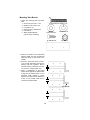
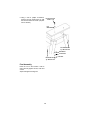
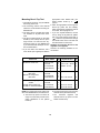
$& 2:1(560$18$/ n8VH:LWKWKHIROORZLQJ5,'*,' %HQFK7RS3RZHU7RROV 666FUROO6DZ 060LWHU6DZ 060LWHU6DZ (%(GJH%HOW6SLQGOH6DQGHU 767DEOH6DZ 737KLFNQHVV3ODQHU n8VH:LWK0DQ\2WKHU%HQFK7RS 7RROV 8QLYHUVDO%HQFK7RS 3RZHU7RRO/HJVWDQG $VVHPEO\ 2SHUDWLRQ 48(67,21625&200(176" &$//5,'*,' ZZZULGJLGZRRGZRUNLQJFRP Form No. SP6227 )RU<RXU6DIHW\ 5HDGDOOLQVWUXFWLRQVFDUHIXOO\ Printed in U.S.A. General Safety Instructions for Power Tools Safety Signal Words 8. Make Workshop Child-proof With padlocks, master switches, or by removing starter keys. 9. Don’t Force Tool It will do the job better and safer at the rate for which it was designed. 10. Use Right Tool Don’t force tool or attachment to do a job it was not designed for. 11. Wear Proper Apparel No loose clothing, gloves, neckties or jewelry (rings, wristwatches), to get caught in moving parts. NON-SLIP footwear is recommended. Wear protective hair covering to contain long hair. Roll long sleeves above the elbow. 12. Use Safety Goggles (Head Protections) The operation of any power tool can result in foreign objects being blown into the eyes, which can result in severe eye damage. Always wear safety goggles, not glasses, complying with ANSI Z87.1 (or in Canada CSA Z94-3-M88) shown on package. Everyday eyeglasses only have impact resistant lenses. They are NOT safety glasses. Safety Goggles are available at many local retail stores. Glasses or goggles not in compliance with ANSI or CSA could seriously hurt you when they break. DANGER: means if the safety information is not followed someone will be seriously injured or killed. WARNING: means if the safety information is not followed someone could be seriously injured or killed. CAUTION: means if the safety information is not followed someone may be injured. 1. Know Your Power Tool Read and understand the owner’s manual and labels affixed to the tool. Learn its application and limitations as well as the specific potential hazards peculiar to this tool. 2. Ground Your Tool If your tool is equipped with an approved 3-conductor cord and a 3prong grounding type plug to fit the proper grounding type receptacle. The green conductor in the cord is the grounding wire. Never connect the green wire to a live terminal. 3. Keep Guards In Place In working order, and in proper adjustment and alignment. 4. Remove Adjusting Keys And Wrenches Form habit of checking to see that keys and adjusting wrenches are removed from tool before turning it on. 5. Keep Work Area Clean Cluttered areas and benches invite accidents. Floor must not be slippery due to wax or sawdust. 6. To Reduce The Risk Of Dangerous Environment Don’t use power tools in damp or wet locations or expose them to rain. Keep work area well lit. Provide adequate surrounding work space. 7. Keep Children Away All visitors should be kept a safe distance from work area. Also, use face or dust mask if cutting operation is dusty, and ear protectors (plugs or muffs) during extended periods of operation. 13. Secure Work Use clamps or a vise to hold work when practical. It’s safer than using your hand, frees both hands to operate tool. 2 14. Don’t Overreach Keep proper footing and balance at all times. 15. Maintain Tools With Care Keep tools sharp and clean for best and safest performance. Follow instructions for lubricating and changing accessories. 16. Disconnect Tools Before servicing; when changing accessories such as blades, bits, cutters, etc. 17. To Reduce The Risk Of Accidental Starting Make sure switch is in “OFF” position before plugging in. Turn switch “OFF” in the event of a power failure. 18. Use Recommended Accessories Consult the owner’s manual for recommended accessories. Follow the instructions that accompany the accessories. The use of improper accessories may cause hazards. 19. Never Stand On Tool Serious injury could occur if the tool is tipped or if the cutting tool is accidentally contacted. Do not store material above or near the tool such that it is necessary to stand on the tool to reach them. 20. Check Damaged Parts Before further use of the tool, a guard or other part that is damaged should be carefully checked to ensure that it will operate properly and perform its intended function. Check for alignment of moving parts, binding of moving parts, breakage of parts, mounting, and any other conditions that may affect its operation. A guard or other part that is damaged should be properly repaired or replaced. If power cord is worn or cut, or damaged in any way, have it replaced immediately. 21. Direction Of Feed Feed work into a blade or cutter against the direction of rotation of the blade or cutter only. 22. Never Leave Tool Running Unattended. Turn power off. Don’t leave tool until it comes to a complete stop. Legstand Safety Instructions May also be used for many other bench top power tools. However, first make sure: • The benchtop power tool does not weigh more than 300 pounds and is evenly distributed on the particle board table top. • The benchtop power tool is securely fastened to the particle board top. • The combined legstand and attached bench top power tool are stable and will not tip. 3 Unpacking and Checking Contents Tools Needed 5/16" Drill Bit 7/16", 1/2 and 9/16" Wrench Hand Drill Phillips Screwdriver Unpacking missing part. The following parts are included: Item Description Qty. A Lower Leg...................................... 4 B Upper Leg...................................... 4 C Lower Stiffener Left ....................... 4 D Lower Stiffener Right..................... 4 E Upper Stiffener .............................. 3 F Upper Stiffener with Logo.............. 1 G Bag of Loose Parts........................ 1 H Table (Particle Board).................... 2 NOTE: Nuts, bolts, screws and washers are shown full size on the following pages. WARNING: For your own safety, turn switch “OFF” and remove plug from power source outlet before mounting power tool onto leg set. NOTE: The Universal Bench Top Power Tool Legstand may be assembled in many different height and width configurations. Separate all parts from packing material and check each part with the illustration until all items are accounted for before discarding any packing materials. If any parts are missing or damaged, do not attempt to continue assembling this item. Call 1-800-4-RIDGID or E-mail us at [email protected] to get the A B #2 Phillips Bit F D G E C H 4 Assembly Introduction Width Adjustment As assembled later, there are three widths to choose from for each of the sides of the legset. Width Adjustment (3 Total) Widest Middle Narrowest Height Adjustment As assembled later, there are five heights to choose from for each leg of the legset. Three are shown below. Height Adjustment (5 Total) Tallest Middle Shortest The Universal Bench Top Power Tool Legstand may be assembled in many different height and width configurations. Many combinations of height and width are possible. 5 Planning for Mounting RIDGID Power Tools Below are the recommended configurations for the RIDGID products currently available. The boards are marked either for: • Drilling holes and mounting tool(s) with screw, washers and nuts. - Or • Using self tapping screws (such as drywall screws) to mount tool(s). MS1250 Miter Saw Height: Tallest Width Left/Right: Widest Width Front/Back: Narrowest MS1050 Miter Saw Height: Tallest Width Left/Right: Widest Width Front/Back: Narrowest 6 SS1650 Scroll Saw Height: Tallest Width Left/Right: Widest Width Front/Back: Narrowest TS2400 Table Saw Height: Shortest Width Left/Right: Widest Width Front/Back: Widest EB4424 Edge Belt Sander Height: Tallest Width Left/Right: Widest Width Front/Back: Narrowest TP1300 Planer Height: Tallest Width Left/Right: Middle Width Front/Back: Widest 7 Planning for Non-RIDGID Tools Other bench top power tools may be mounted on this legset. However, first make sure: • The benchtop power tool does not weigh more than 300 pounds and is evenly distributed on the particle board table top. • The benchtop power tool is securely fastened to the particle board top. • The combined legstand and attached bench top power tool are stable and will not tip. If your tool is similar to one of the above, use that setup configuration. General Assembly Attaching Leveling Feet 1. Locate the following parts and hardware. 8 Hex Jam Nuts, 3/8-16 4 Leveling Feet 4 Lower Legs 2. Thread hex nut to within 1/4 inch of the bottom of each of the four leveling feet. 3. Install leveling feet through holes in lower legs as shown. Finger tighten nuts. 4. Final adjustment and tightening of the leveling feet will be needed once you have completed the entire assembly process. Hex Jam Nut 3/8-16 Leveling Foot Lower Leg Leveling Foot 8 Assembling Upper and Lower Legs 1. Locate the following parts and hardware: 8 Carriage Bolts 5/16-18 x 5/8" 8 Hex Flanged Nuts 5/16-18 4 Lower Legs (with leveling feet attached) 4 Upper Legs Carriage Bolts 5/16-18 x 5/8 Upper Leg Hex Flanged Nut 5/16-18 Lower Leg w/ Leveling Foot 2. Position the lower leg inside the upper leg for the desired height setting. NOTE: The minimum height of the legstand is 24" and the maximum is 34". The distance between holes in the lower leg(s) is approximately 2-1/2". The actual height setting will depend on the type of tool and the operator’s preference. 3. Place a carriage bolt through only the bottom hole of the upper leg and then throught the desired hole in the lower leg. Finger tighten nut. 9 Assembling Lower Stiffeners 1. Locate the following parts and hardware: 16 Carriage Bolts 5/16-18 x 5/8" 16 Hex Flanged Nuts 5/16-18 4 Lower Stiffeners Left 4 Lower Stiffeners Right NOTE: Lower Stiffeners are stamped left and right. 2. Position the lower stiffener left on the inside of the left leg assembly and secure with carriage bolt and nut as shown. Finger tighten only. Carriage Bolts 5/16-18 x 5/8 Lower Left Stiffener Hex Flanged Nut 5/16-18 Lower Right Stiffener Nut Carriage Bolt Lower Left Stiffener 3. Position the lower stiffener right on the inside of the right leg assembly and secure with carriage bolt and nut as shown. Finger tighten only. Nut Carriage Bolt Lower Right Stiffener 10 4. Position the left lower stiffener inside the right lower stiffener for the desired width setting. 5. Place two carriage bolts through the assembly and finger tighten each nut. Assembling Upper Stiffener 1. Locate the following parts and hardware: 16 Carriage Bolts 5/16-18 x 5/8 16 Hex Flanged Nuts 5/16-18 4 Upper Stiffeners (one with logo) Hex Flanged Nut 5/16-18 Carriage Bolts 5/16-18 x 5/8 Upper Stiffener 2. Position the upper leg/lower stiffener required setting. 3. Place two carriage hole as shown and nut. stiffener inside the assembly at the bolts through each finger tighten each 11 Mounting Table Boards 1. Locate the following parts and hardware: 4 Screw Pan Hd 1/4-20 x 1-1/4 8 Washers 17/64 x 5/8 x 1/16 4 Lockwashers 1/4 4 Screw Pan Hd Ty “AB” #8 x 3/4 4 Hex Nuts 1/4 2 Tables (Particle Board) (Layout marks not shown) Screw Pan Hd. 1/4-20 x 1-1/4 Washer 17/64 x 5/8 x 1/16 Lockwasher 1/4 Screw Pan Hd Ty “AB” #8 x 3/4 Hex Nut 1/4 Table 2. Position the tables on the assembled legstand. Make sure the counterbored holes are facing up and closer to the outside. 3. Place two pan head screws 1/4-20 x 1-1/4 through flat washer through the table(s) and then legstand. Secure with flat washer, lockwasher and hex nut as shown. Finger tighten only. 4. Place a straightedge or flat board against the 8" edge of the table boards to align the two table boards. For the narrowest width maintain 4 inches between the table boards. Maintain 6 inches for the middle width and 8 inches for the widest width. 4" 6" Straightedge 8" 12 5. Using a drill or phillips screwdriver, drive the four pan head screws Ty “AB” #8 x 3/4 from below as shown. (No pilot hole is needed.) Pan Head Screw 1/4-20 x 1-1/4 Flat Washer Pan Head Screw Ty “AB” #8 x 3/4 Flat Washer Lockwasher Hex Nut Pan Head Screw Ty “AB” #8 x 3/4 Final Assembly Place the tool in the location it will be used. Securely tighten all nuts, bolts and screws. Adjust and tighten leveling feet. 13 Mounting Bench Top Tool 1. The table is “layed-out” only for RIDGID bench top power tools. 2. The “Planning” section of this manual shows the recommended mounting for RIDGID tools. 3. The tools can be mounted with “bolt & nut” hardware or “drywall screw” hardware. 4. The layout marks printed on the table boards (in most cases) will line up the larger “bolt & nut” holes and the “drywall screw” holes on your RIDGID tool if you assembled the stand per our earlier recommendation. 5. If you use “bolt & nut” fasteners, use a 5/16" drill bit (not supplied) and drill the appropriate holes labeled with your model number shown by a “ ” symbol. 6. Place the appropriate bolt through the bench top power tool and table(s). Place a flat washer, lockwasher and nut on the bolt. Securely tighten nut. 7. If you use “drywall” fasteners, line the tool up using the drywall hole pattern with your model number shown with a “ X ”. Place the drywall screws through the smaller holes in the tool base and then drive them into the wood. Hardware for mounting the tool to the legstand is not supplied. However, the following hardware is recommended. Fastener Hardware Power Tool Qty. Drywall Screws Qty. 1/4-20 x 2" Bolt 1/4-20 Nut 1/4 Lockwasher 1/4 Flat Washer 3 3 3 3 #10 x 1-1/2" Screw Washer - ID 1/4" 3 3 MS1050 10" Compound Miter Saw MS1250 12" Compound Miter Saw 1/4-20 x 2-1/2 Bolt 1/4-20 Nut 1/4 Lockwasher 1/4 Flat Washer 4 4 4 4 #8 x 1-3/4" Screw 4 #8 x 1-3/4" Screw 4 EB4424 Oscillating Edge/Belt Sander TS2400 Jobsite Table Saw TP1300 13" Thickness Planer 1/4-20 x 3-1/2" Bolt 1/4-20 Nut 1/4 Lockwasher 1/4 Flat Washer 4 4 4 4 #8 x 3" Screw 4 #8 x 3-1/4" Screw #8 x 2-3/4" Screw 4 4 SS1650 16" Scroll Saw Bolts & Nuts b. The bench top power tool is securely NOTE: If mounting bench top power tools other than RIDGID brand, be certain that: fastened to the particle board top. a. The bench top power tool must not c. The combined legstand and weigh more than 300 pounds and is attached bench top power tool are stable and will not tip. evenly distributed on the particle board top. 3.. 14 Repair Parts Power Tool Legstand Model Number AC99100 RIDGID parts are available at www.ridgidparts.com 1 1 2 13 2 4 3 13 6 5 3 6 14 7 10 11 8 8 12 9 15 Key No. 1 Part No. * 2 3 4 827562 827558 827642 5 6 827557 7 827556 * Description Screw Pan Hd 1/4-20 x 1-1/4 Table Stiffener Upper Bolt Carriage Short Neck 5/16-18 x 1/2 Leg Upper Screw Pan Hd #8 x 3/4 Leg Lower Key No. 8 9 10 11 12 Description Nut Hex 3/8-16 * 803835-3 Foot Leveling 3/8 Stiffener Lower Right 827560 Stiffener Lower Left 827561 826817-1 Nut Hex Flange 5/16 -18 13 Washer * 17/64 x 5/8 x 1/16 14 Lockwasher 1/4 * 15 SP6227 Owners Manual * Standard hardware - may be purchased locally. 15 Part No. QUESTIONS OR COMMENTS? CALL 1-800-4-RIDGID www.ridgidwoodworking.com RIDGID Power Tools Emerson Electric Co. © 1999 Emerson Electric Co. Form No. SP6227-1 Printed in U.S.A. 12/99