1
MLC 52 Series
MediaLink™ Controllers
68-1079-01 Rev. D
04 07
Precautions
Safety Instructions • English
Warning
This symbol is intended to alert the user of important operating and maintenance
(servicing) instructions in the literature provided with the equipment.
Power sources • This equipment should be operated only from the power source indicated on the product.
This equipment is intended to be used with a main power system with a grounded (neutral)
conductor. The third (grounding) pin is a safety feature, do not attempt to bypass or disable it.
This symbol is intended to alert the user of the presence of uninsulated dangerous
voltage within the product's enclosure that may present a risk of electric shock.
Power disconnection • To remove power from the equipment safely, remove all power cords from the rear
of the equipment, or the desktop power module (if detachable), or from the power source receptacle
(wall plug).
Power cord protection • Power cords should be routed so that they are not likely to be stepped on or
pinched by items placed upon or against them.
Caution
Read Instructions • Read and understand all safety and operating instructions before using the
equipment.
Retain Instructions • The safety instructions should be kept for future reference.
Servicing • Refer all servicing to qualified service personnel. There are no user-serviceable parts inside. To
prevent the risk of shock, do not attempt to service this equipment yourself because opening or
removing covers may expose you to dangerous voltage or other hazards.
Follow Warnings • Follow all warnings and instructions marked on the equipment or in the user
information.
Slots and openings • If the equipment has slots or holes in the enclosure, these are provided to prevent
overheating of sensitive components inside. These openings must never be blocked by other objects.
Avoid Attachments • Do not use tools or attachments that are not recommended by the equipment
manufacturer because they may be hazardous.
Lithium battery • There is a danger of explosion if battery is incorrectly replaced. Replace it only with the
same or equivalent type recommended by the manufacturer. Dispose of used batteries according to the
manufacturer's instructions.
Consignes de Sécurité • Français
Avertissement
Ce symbole sert à avertir l’utilisateur que la documentation fournie avec le matériel
contient des instructions importantes concernant l’exploitation et la maintenance
(réparation).
Alimentations• Ne faire fonctionner ce matériel qu’avec la source d’alimentation indiquée sur l’appareil.
Ce matériel doit être utilisé avec une alimentation principale comportant un fil de terre (neutre). Le
troisième contact (de mise à la terre) constitue un dispositif de sécurité : n’essayez pas de la
contourner ni de la désactiver.
Ce symbole sert à avertir l’utilisateur de la présence dans le boîtier de l’appareil de
tensions dangereuses non isolées posant des risques d’électrocution.
Déconnexion de l’alimentation• Pour mettre le matériel hors tension sans danger, déconnectez tous les
cordons d’alimentation de l’arrière de l’appareil ou du module d’alimentation de bureau (s’il est
amovible) ou encore de la prise secteur.
Attention
Lire les instructions• Prendre connaissance de toutes les consignes de sécurité et d’exploitation avant
d’utiliser le matériel.
Conserver les instructions• Ranger les consignes de sécurité afin de pouvoir les consulter à l’avenir.
Respecter les avertissements • Observer tous les avertissements et consignes marqués sur le matériel ou
présentés dans la documentation utilisateur.
Eviter les pièces de fixation • Ne pas utiliser de pièces de fixation ni d’outils non recommandés par le
fabricant du matériel car cela risquerait de poser certains dangers.
Sicherheitsanleitungen • Deutsch
Dieses Symbol soll dem Benutzer in der im Lieferumfang enthaltenen
Dokumentation besonders wichtige Hinweise zur Bedienung und Wartung
(Instandhaltung) geben.
Dieses Symbol soll den Benutzer darauf aufmerksam machen, daß im Inneren des
Gehäuses dieses Produktes gefährliche Spannungen, die nicht isoliert sind und
die einen elektrischen Schock verursachen können, herrschen.
Achtung
Lesen der Anleitungen • Bevor Sie das Gerät zum ersten Mal verwenden, sollten Sie alle Sicherheitsund Bedienungsanleitungen genau durchlesen und verstehen.
Aufbewahren der Anleitungen • Die Hinweise zur elektrischen Sicherheit des Produktes sollten Sie
aufbewahren, damit Sie im Bedarfsfall darauf zurückgreifen können.
Befolgen der Warnhinweise • Befolgen Sie alle Warnhinweise und Anleitungen auf dem Gerät oder in
der Benutzerdokumentation.
Keine Zusatzgeräte • Verwenden Sie keine Werkzeuge oder Zusatzgeräte, die nicht ausdrücklich vom
Hersteller empfohlen wurden, da diese eine Gefahrenquelle darstellen können.
Instrucciones de seguridad • Español
Protection du cordon d’alimentation • Acheminer les cordons d’alimentation de manière à ce que
personne ne risque de marcher dessus et à ce qu’ils ne soient pas écrasés ou pincés par des objets.
Réparation-maintenance • Faire exécuter toutes les interventions de réparation-maintenance par un
technicien qualifié. Aucun des éléments internes ne peut être réparé par l’utilisateur. Afin d’éviter tout
danger d’électrocution, l’utilisateur ne doit pas essayer de procéder lui-même à ces opérations car
l’ouverture ou le retrait des couvercles risquent de l’exposer à de hautes tensions et autres dangers.
Fentes et orifices • Si le boîtier de l’appareil comporte des fentes ou des orifices, ceux-ci servent à
empêcher les composants internes sensibles de surchauffer. Ces ouvertures ne doivent jamais être
bloquées par des objets.
Lithium Batterie • Il a danger d'explosion s'll y a remplacment incorrect de la batterie. Remplacer
uniquement avec une batterie du meme type ou d'un ype equivalent recommande par le constructeur.
Mettre au reut les batteries usagees conformement aux instructions du fabricant.
Vorsicht
Stromquellen • Dieses Gerät sollte nur über die auf dem Produkt angegebene Stromquelle betrieben
werden. Dieses Gerät wurde für eine Verwendung mit einer Hauptstromleitung mit einem geerdeten
(neutralen) Leiter konzipiert. Der dritte Kontakt ist für einen Erdanschluß, und stellt eine
Sicherheitsfunktion dar. Diese sollte nicht umgangen oder außer Betrieb gesetzt werden.
Stromunterbrechung • Um das Gerät auf sichere Weise vom Netz zu trennen, sollten Sie alle Netzkabel
aus der Rückseite des Gerätes, aus der externen Stomversorgung (falls dies möglich ist) oder aus der
Wandsteckdose ziehen.
Schutz des Netzkabels • Netzkabel sollten stets so verlegt werden, daß sie nicht im Weg liegen und
niemand darauf treten kann oder Objekte darauf- oder unmittelbar dagegengestellt werden können.
Wartung • Alle Wartungsmaßnahmen sollten nur von qualifiziertem Servicepersonal durchgeführt
werden. Die internen Komponenten des Gerätes sind wartungsfrei. Zur Vermeidung eines
elektrischen Schocks versuchen Sie in keinem Fall, dieses Gerät selbst öffnen, da beim Entfernen der
Abdeckungen die Gefahr eines elektrischen Schlags und/oder andere Gefahren bestehen.
Schlitze und Öffnungen • Wenn das Gerät Schlitze oder Löcher im Gehäuse aufweist, dienen diese zur
Vermeidung einer Überhitzung der empfindlichen Teile im Inneren. Diese Öffnungen dürfen niemals
von anderen Objekten blockiert werden.
Litium-Batterie • Explosionsgefahr, falls die Batterie nicht richtig ersetzt wird. Ersetzen Sie verbrauchte
Batterien nur durch den gleichen oder einen vergleichbaren Batterietyp, der auch vom Hersteller
empfohlen wird. Entsorgen Sie verbrauchte Batterien bitte gemäß den Herstelleranweisungen.
Advertencia
Este símbolo se utiliza para advertir al usuario sobre instrucciones importantes de
operación y mantenimiento (o cambio de partes) que se desean destacar en el
contenido de la documentación suministrada con los equipos.
Alimentación eléctrica • Este equipo debe conectarse únicamente a la fuente/tipo de alimentación eléctrica
indicada en el mismo. La alimentación eléctrica de este equipo debe provenir de un sistema de
distribución general con conductor neutro a tierra. La tercera pata (puesta a tierra) es una medida de
seguridad, no puentearia ni eliminaria.
Este símbolo se utiliza para advertir al usuario sobre la presencia de elementos con
voltaje peligroso sin protección aislante, que puedan encontrarse dentro de la caja
o alojamiento del producto, y que puedan representar riesgo de electrocución.
Desconexión de alimentación eléctrica • Para desconectar con seguridad la acometida de alimentación
eléctrica al equipo, desenchufar todos los cables de alimentación en el panel trasero del equipo, o
desenchufar el módulo de alimentación (si fuera independiente), o desenchufar el cable del
receptáculo de la pared.
Precaucion
Protección del cables de alimentación • Los cables de alimentación eléctrica se deben instalar en lugares
donde no sean pisados ni apretados por objetos que se puedan apoyar sobre ellos.
Leer las instrucciones • Leer y analizar todas las instrucciones de operación y seguridad, antes de usar
el equipo.
Reparaciones/mantenimiento • Solicitar siempre los servicios técnicos de personal calificado. En el interior
no hay partes a las que el usuario deba acceder. Para evitar riesgo de electrocución, no intentar
personalmente la reparación/mantenimiento de este equipo, ya que al abrir o extraer las tapas puede
quedar expuesto a voltajes peligrosos u otros riesgos.
Conservar las instrucciones • Conservar las instrucciones de seguridad para futura consulta.
Obedecer las advertencias • Todas las advertencias e instrucciones marcadas en el equipo o en la
documentación del usuario, deben ser obedecidas.
Evitar el uso de accesorios • No usar herramientas o accesorios que no sean especificamente
recomendados por el fabricante, ya que podrian implicar riesgos.
Ranuras y aberturas • Si el equipo posee ranuras o orificios en su caja/alojamiento, es para evitar el
sobrecalientamiento de componentes internos sensibles. Estas aberturas nunca se deben obstruir con
otros objetos.
Batería de litio • Existe riesgo de explosión si esta batería se coloca en la posición incorrecta. Cambiar esta
batería únicamente con el mismo tipo (o su equivalente) recomendado por el fabricante. Desachar las
baterías usadas siguiendo las instrucciones del fabricante.
ᅝܼ乏ⶹ •Ё᭛
䖭Ͼヺোᦤ⼎⫼᠋䆹䆒⫼᠋ݠЁ
᳝䞡㽕ⱘ᪡㓈ᡸ䇈ᯢDŽ
䖭Ͼヺো䄺ਞ⫼᠋䆹䆒ᴎݙ᳝
䴆ⱘॅ䰽⬉य़ˈ᳝㾺⬉ॅ䰽 ɿ
䄺ਞ
⬉⑤• 嬦嫿⡈⌫倾Ề䑩ᷨ␂ᵋ㝈㕏䗅䑶㷑ɿ嫿⡈⼆枼 Ề䑩㙊♱一䗅Ờ䑶䰼丠Ờ䑶ɿ
䩭ᵊ㚢一澠♱一澡㕰 ⫊₩嫿㓾澤ᵎ倾ᵎ䑩ㅗ崴弈ɿ
ᢨᥝ⬉⑤• ᵻ⫊₩♱ḏ嫿⡈㈕㋊䑶㷑澤嬸㈕㋊ㆁ㙊嫿 ⡈⍏ㅗ㞍暣䑶㷑䗅䑶㷑一澤
ㅗḼẖ㋦ⅱⵃ䑶䰼丠䗅 䑶㷑一ɿ
⊼ᛣ
⬉⑤㒓ֱᡸ• ⣦Ⓟⵄ一澤忀₎埬嵪嵐澤ㅗ愎䆪㉥⋌ɿ
䯙䇏䇈ᯢк• 䑩ㅸỀ䑩嬦嫿⡈⼆枼敆嬼䍇夤ㆁ㙊⫊₩⏍Ề䑩嬵㕏ɿ
㓈ᡸ• ㆁ㙊丵Ἧ⼆枼䑲嫥嬂䗅丵Ἧ᷻⎙弜垍ɿ嫿⡈ 怩㯢㙊䑩ㅸ⌰Ḧ㘵㊣䗅昷ḷɿ
ֱᄬ䇈ᯢк• 䑩ㅸⷕ⪙⫊₩嬵㕏ᶧḦ⡈⭇㚦Ề䑩ɿ
䙉ᅜ䄺ਞ • 䑩ㅸⷕ徶⫉ᷨ␂⏍䑩ㅸ㉈⊘ᵋ䗅ㆁ㙊⫊₩ ⏍㐎ẝ嬵㕏ɿ
䙓ܡ䗑ࡴ •
ᵎ壂Ề䑩嬦ᷨ␂⋃⒇㯢㙊㋩劑䗅₸ㅗ弾 ⇡嫿⡈澤Ḧ忀₎⊲斪 ɿ
ᵻ忀₎℻䋱大䑶⊲斪 ᵎ壂儫ⴲ嬖☿㆔⹁嫿⡈䘗⪑丵Ἧ嬦嫿⡈ɿ
䗮亢ᄨ• 㙊ᷜ嫿⡈㙻⠴ᵋ㙊彛栏㤾ㅗ⪕澤⫄ḭ㕰䑩㚦 敳㪣㙻㒐だ₄ḷ弈䀮ɿ
ᵎ壂䑩Ḽẖᵝ壀㉢Ẑ彛 栏⪕ɿ
䫖⬉∴• ᵎ㪤䞯䗅㘵㊣䑶㮡ṛ㙊䅇㿹䗅⊲斪ɿ⼆枼Ề䑩 ᵏ⋃⫷㋩劑䗅䘹⍍ㅗ䘹弒⛌⌸䗅䑶㮡ɿ
㉊䂨䑠ᷨ⋃ 䗅⸻嫯⡅䍇ⷠ⹄䑶㮡ɿ
Table of Contents
Chapter 1 • Introduction ....................................................................................................... 1-1
About the MLC 52 Series ................................................................................................. 1-2
Features and Options ........................................................................................................ 1-2
Standard features .............................................................................................................. 1-2
Options and accessories ..................................................................................................... 1-3
MLC 52 Application Examples ...................................................................................... 1-4
Chapter 2 • Installation .......................................................................................................... 2-1
Installation Overview ....................................................................................................... 2-2
UL Requirements ................................................................................................................. 2-3
Installation Procedures .................................................................................................... 2-3
Preparing the site and installing the wall box ................................................................. 2-3
Replacing the faceplate ..................................................................................................... 2-4
Replacing button labels ..................................................................................................... 2-5
Mounting an electrical box ............................................................................................... 2-6
Rear panel and cable connections .................................................................................... 2-8
Wiring the control connector ................................................................................... 2-10
Wiring for IR control ........................................................................................... 2-11
Wiring for RS-232 control (RS models only) ....................................................... 2-12
Wiring an IR Link ................................................................................................. 2-12
Wiring an IRL 20 .................................................................................................. 2-14
Wiring the power connector .............................................................................. 2-15
Wiring the VC port .................................................................................................... 2-15
Mounting the MLC 52 ..................................................................................................... 2-16
Mounting the MLC to an electrical box or mounting bracket ............................... 2-16
Mounting the MLC to a wall or furniture ............................................................... 2-17
Chapter 3 • Operation ............................................................................................................. 3-1
Display Device Control ..................................................................................................... 3-2
Front Panel Features and Operation ......................................................................... 3-2
Buttons on the front panel ............................................................................................... 3-2
Switch modes ..................................................................................................................... 3-2
Front panel components ................................................................................................... 3-3
Configuring the MLC 52 Using IR ................................................................................ 3-5
Configuring using IR data transfer ................................................................................... 3-5
Configuring using IR Learning .......................................................................................... 3-7
Removing commands from a button ................................................................................ 3-9
Setting up button macros ................................................................................................. 3-9
Configuring a single button for input source selection ................................................ 3-10
Using the MLC 52 VC Models with the MPA Series Power Amplifiers ... 3-11
Requirements for the MLC 52 with volume control knob ............................................. 3-11
Wiring and connections for the MLC 52 VC models ...................................................... 3-12
Configuring the MLC 52 IR and MLC 52 RS Vol buttons ................................................ 3-12
MLC 52 Series MediaLink Controllers • Table of Contents
i
Table of Contents, cont’d
Powering the Display Device On and Off ............................................................. 3-12
Powering on ..................................................................................................................... 3-12
Powering off .................................................................................................................... 3-13
Selecting Inputs ................................................................................................................. 3-13
Operating the MLC 52 Using IR Remote Control ............................................... 3-14
Buttons on the IR 452 remote control ............................................................................ 3-15
Resetting ............................................................................................................................... 3-16
Locking the Front Panel (Executive Mode) .......................................................... 3-16
Chapter 4 • Special Applications ..................................................................................... 4-1
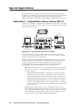
Application 1: Using Multiple Sources with an MLC 52 ................................. 4-2
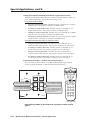
Programming buttons for an IR controlled system .......................................................... 4-3
Projector remote control type A (application 1) ....................................................... 4-3
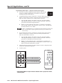
Projector remote control type B (application 1) ....................................................... 4-6
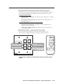
Programming buttons for multiple inputs on an RS-232 controlled system .................. 4-7
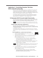
Application 2: Projector Requiring a Power Off Confirmation .................. 4-7
Configuring the MLC 52 for a power-off confirmation ................................................... 4-8
Application 3: Controlling Projectors That Have Multi-coded
IR Functionality .................................................................................................................... 4-9
Configuring the MLC 52 for multi-coded IR functionality .............................................. 4-9
Projector remote control type A (application 3) ....................................................... 4-9
Programming RGB inputs — projector remote control type A ........................... 4-9
Programming video inputs — projector remote control type A ....................... 4-10
Issuing input selection commands learned from a type A remote control ...... 4-12
Programming VC models — projector remote control type A ......................... 4-12
Projector remote control type B (application 3) ..................................................... 4-13
Programming RGB inputs — projector remote control type B ......................... 4-13
Programming video inputs — projector remote control type B ....................... 4-14
Issuing input selection commands learned from remote control type B ......... 4-15
Programming VC models — Projector remote control type B ......................... 4-15
Chapter 5 • Serial Communication ................................................................................. 5-1
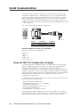
Using the MLC 52 Configuration Program ............................................................. 5-2
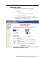
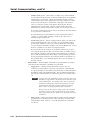
Installing the software ...................................................................................................... 5-3
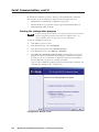
Starting the configuration program ................................................................................. 5-4
Loading Extron drivers ...................................................................................................... 5-5
Loading the serial (RS-232) drivers ............................................................................. 5-5
Loading the IR drivers ................................................................................................. 5-5
Viewing the IR driver package version ...................................................................... 5-7
Changing the location of the IR drivers ..................................................................... 5-8
Key to file names ............................................................................................................... 5-9
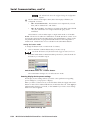
Configuring using the MLC 52 Configuration Wizard ..................................................... 5-9
Creating a new configuration using the wizard ..................................................... 5-11
Opening an existing configuration using the wizard ............................................. 5-17
Configuring using the Windows-based configuration program ................................... 5-19
ii
MLC 52 Series MediaLink Controllers • Table of Contents
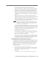
Overview of the configuration procedure .............................................................. 5-20
Opening the MLC 52 Configuration Program screen .............................................. 5-20
Displaying the Help program ................................................................................... 5-23
Saving and restoring a configuration ...................................................................... 5-23
Saving a configuration ........................................................................................ 5-23
Restoring a configuration ................................................................................... 5-24
Overview of the MLC 52 configuration program main screen ............................... 5-25
Menu bar ............................................................................................................. 5-26
Front panel representations ............................................................................... 5-28
Button Settings area ............................................................................................ 5-29
Display settings tabs ............................................................................................ 5-29
Button Operations area ...................................................................................... 5-29
Adding a driver ......................................................................................................... 5-30
Removing a driver ..................................................................................................... 5-32
Removing an IR driver ......................................................................................... 5-32
Removing a serial driver ...................................................................................... 5-32
Assigning functions to buttons ................................................................................ 5-32
Assigning user-defined functions to buttons .......................................................... 5-34
Removing a function from a button ........................................................................ 5-35
Setting up button modes and labels ........................................................................ 5-35
Factory defaults ................................................................................................... 5-37
Setting the button modes ................................................................................... 5-38
Entering display device power settings ................................................................... 5-38
Entering display device communications port settings .......................................... 5-39
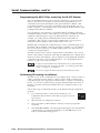
Programming the MLC 52 for control by the IR 452 Remote ........................................ 5-40
Performing IR Learning via software .............................................................................. 5-40
Playing an IR command ................................................................................................... 5-42
Using emulation mode .................................................................................................... 5-43
Selecting the starting screen ........................................................................................... 5-46
Resetting .......................................................................................................................... 5-47
Uploading firmware ........................................................................................................ 5-48
Downloading the firmware from the Web ............................................................. 5-48
Installing the Firmware Loader ................................................................................ 5-49
Updating the firmware ............................................................................................. 5-49
Using Simple Instruction Set (SIS™) commands ................................................. 5-51
Host-to-MLC communications ......................................................................................... 5-51
MLC-initiated messages ............................................................................................ 5-51
Error responses .......................................................................................................... 5-51
Using the command/response tables ....................................................................... 5-51
Symbol definitions .................................................................................................... 5-52
Command/response table for SIS commands ................................................................. 5-53
Command/response table for advanced instructions
(for the MLC 52 configuration program) ....................................................................... 5-54
MLC 52 Series MediaLink Controllers • Table of Contents
iii
Table of Contents, cont’d
Appendix A • Specifications, Part Numbers, and Accessories .................... A-1
Specifications ....................................................................................................................... A-2
Part Numbers and Accessories ......................................................................................... A-3
Included parts ................................................................................................................... A-3
Optional accessories ......................................................................................................... A-4
Cables ................................................................................................................................ A-4
Appendix B • Templates ......................................................................................................... B-1
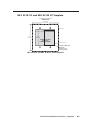
MLC 52 IR and MLC 52 RS Template ................................................................ B-2
MLC 52 IR VC and MLC 52 RS VC Template ............................................................. B-3
All trademarks mentioned in this manual are the properties of their respective owners.
68-1079-01 Rev. D
04 07
iv
MLC 52 Series MediaLink Controllers • Table of Contents
MLC 52 Series
1
Chapter One
Introduction
About the MLC 52 Series
Features and Options
MLC 52 Application Examples
Introduction
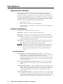
About the MLC 52 Series
The Extron MediaLink™ Controller 52 (MLC 52) Series provide RS-232 and/or
infrared (IR) remote control of a projector or other display device. They are
economical, compact (one-gang or two-gang size), easy-to-use controllers for use
with audiovisual equipment in sites such as elementary or high school classrooms,
or small conference rooms. The MLC 52 acts as a universal remote control panel,
providing control for a display device’s power, input selection, volume, and more.
The MLC 52 can be configured using three different methods:
•
Infrared (IR) learning
•
IR data transfer (“beaming”) from another MLC 52
•
Using Extron device control drivers with the Windows®-based configuration
software program
Features and Options
The MLC 52 is available in the following models:
MLC 52 IR — 1-gang size; controls the display device by IR.
MLC 52 RS — 1-gang size; controls the display device by either IR or RS-232.
MLC 52 IR VC — 2-gang size; controls the display device via IR. This model has a
volume control knob to control an amplifier such as the Extron MPA Mini
Power Amplifier (purchased separately).
MLC 52 RS VC — 2-gang size; controls the display device by either IR or RS-232.
This model has a volume control knob to control an amplifier such as the
Extron MPA Mini Power Amplifier (purchased separately).
The terms “MLC,” “MLC 52,” and “controller” are used interchangeably in
this manual to refer to all four models of the MediaLink controller unit,
regardless of which faceplate is attached to it. The cabling, operation, and
setup are identical for all models; the models differ only in how they are
controlled.
Standard features
IR and RS-232 ports for universal display device control — The MLC 52 has a
dedicated port for communicating with virtually any projector or display via
infrared (IR) signal. The MLC 52 RS models also have ports for
unidirectional RS-232 wired serial control. Projector control drivers can be
downloaded from the Extron Web site or created using the Windows-based
configuration program.
Discrete On and Off display device power controls — These controls simplify
system operations and eliminate the need for a device’s handheld remote
control.
Configurable, backlit buttons — The configurable buttons can be set up to control
display device power, volume, input selection, or any other IR or RS-232
command function supported by the device. The buttons are backlit and can
be custom labeled, offering easy operation for presenters in low-light
environments.
Macro and toggle button modes — Each button on the MLC can be programmed
to send out up to four IR or serial commands. You can set each button either
to issue all its commands with one press (macro mode) or to issue one of its
commands at a time, in sequence, with each button press (toggle mode).
1-2
MLC 52 Series MediaLink Controllers • Introduction
Front panel configuration port — This RS-232 serial port enables advanced
configuration, driver downloads, and firmware updates to be performed
from the front panel without the need to remove the controller from its
mounting. The optional Extron configuration cable (part #70-335-01) can be
used to connect the MLC 52 to the PC’s RS-232 port.
Three configuration methods — The MLC 52 can be configured easily using the
following methods:
•
IR learning — Allows the MLC 52 to be set up directly from the display
device’s remote control without the need for software.
•
IR data transfer — Duplicates complete configuration information from
one MLC 52 model to another without cables or software.
•
Windows-based configuration software — Combined with one of the
many IR or RS-232 drivers that are provided with the controller on CD or
available on the Extron Web site, Extron’s MLC 52 Configuration
Program software provides fast and simple setup.
Inactivity timer for display shutoff — Adjustable timer control provides automatic
shutdown of the display device to conserve energy, prevent plasma burn-in,
and extend projector lamp life.
Front panel security lockout — Front panel lockout (executive mode) can be
implemented if the MLC 52 is installed in an unsecured environment where
universal access is not desirable.
High-impact mounting faceplates — The standard MLC 52 models are provided
with two one-gang sized high-impact plastic faceplates (one black and one
white), that are durable enough for demanding environments.
The MLC 52 VC models include two two-gang sized high impact plastic
faceplates (one black and one white).
Flexible mounting options — With a standard electrical box or one of the included
mounting brackets (“mud rings”), the MLC 52 can be mounted in a wide
variety of locations, including walls, lecterns, and tables.
Volume control (VC) faceplate — The two-gang sized MLC 52 IR VC and the
MLC 52 RS VC each have a volume control knob in addition to the six control
buttons. To use this knob, you must connect the MLC 52 to a power amplifier
(purchased separately), such as the Extron MPA Series Mini Power Amplifier,
to which you also connect the projector or display (see the application
diagram on page 1-4). The volume control knob adjusts the volume on the
amplifier. This option frees up the two volume control buttons on the MLC to
be used or reconfigured for other display device functions.
Options and accessories
MPA Series Mini Power Amplifier — Connect an MPA 122 (part #60-668-01) or an
MPA 181T (part #60-747-01) to the volume control port of the MLC 52 VC
models, and to your projector or display and speakers. This enables you to
use the MLC’s volume knob to control the volume of the speakers via the
MPA.
Remote control — The optional IR 452 Remote Control and optional IR signal
repeater provide infrared remote control of the MLC unit from up to 30 feet
away.
The Extron P/S 100 and other Extron power supplies may be used with the
MLC 52.
MLC 52 Series MediaLink Controllers • Introduction
1-3
Introduction, cont’d
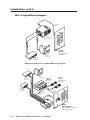
MLC 52 Application Examples
IR or RS-232
Control
DI
SP
Y
LA
F
OF
ON
Projector w/
Internal Speakers
PC
L
VO
EO
VID
L
VO
ML
2
C5
Extron
MLC 52
Basic MediaLink
Controller
PC
VGA w/
Audio Cable
DVD
Composite
Audio RCA
Application diagram for a standard MLC 52 (1-gang size)
PC
DVD
VGA w/
Audio Cable
Extron
SPC 62
Extron
MPA 122
S-video
Audio RCA
Ceiling Speakers
(in parallel)
Mini Power
Amplifier
2
12
A
MP UTS
TP
OU hms
O
4/8
US
C
U
INP
OTE
TS
REM
R
L
E
R
VCR
Composite
Audio RCA
L
V
10 MUT
L/
VO
L
WER
PO
R
Volume
Control
Switched Audio
Output
DI
SP
Y
LA
F
OF
ON
US
C
PC
IR or RS-232
Control
E
UM
L
VO
D
DV
R
VC
ML
2
C5
Extron
MLC 52 RS VC
Projector
1-4
MLC 52 Series MediaLink Controllers • Introduction
Basic MediaLink Controller
with Volume Control
MLC 52 Series
2
Chapter Two
Installation
Installation Overview
UL Requirements
Installation Procedures
Installation
Installation Overview
CAUTION
Installation and service must be performed by authorized personnel only. UL
listed electrical boxes are recommended. See “UL Requirements,” on the
next page.
To install and set up the MLC, follow these steps:
1
If applicable, prepare the installation site: cut a hole in the wall, install the
electrical box or mounting bracket (“mud ring”), and prepare the cables.
Instructions are included in this manual and/or with the optional faceplate,
mounting device, or wall box.
Metal versions of the one-gang and VC faceplates are available as options.
See “Preparing the site and installing the wall box,” later in this chapter.
2
Make and/or install button labels as desired. See “Replacing button labels,”
later in this chapter.
3
If you want to use a different faceplate from the one that is attached, remove
the installed faceplate from the MLC, and replace it with the new one. See
“Replacing the faceplate,” later in this chapter.
4
Attach cables to the rear of the MLC and to the display device; MPA Mini
Power Amplifier (if applicable); and optional IR Link, IR Emitters, and/or
IRL 20.
5
Connect power cords and turn on all the devices, including the MLC.
6
Configure the controller by using one of the following methods:
•
IR learning (See “Configuring using IR learning,” in chapter 3,
“Operations.”)
•
IR data transfer (cloning) (See “Configuring using data transfer,” in
chapter 3, “Operations.”)
•
Windows®-based configuration software program (See “Using the
MLC 52Configuration Program” in chapter 5, “Serial Communication,”
for detailed information on the configuration software.)
7
Test the system: press the MLC’s buttons, watch the display, and listen to the
audio output to determine whether the output devices are responding
correctly (powering on/off, switching inputs, etc.). If not, ensure that all
devices are plugged in and receiving power. Check the cabling, and make
adjustments as needed.
8
Mount the MLC to the wall or furniture.
a.
b.
c.
d.
2-2
Disconnect the MLC’s power supply at the power source end (not at the
MLC end).
Disconnect the other devices’ power.
Secure the faceplate onto a UL-approved electrical wall box, a mounting
bracket, a wall, or furniture. See “Mounting the MLC 52,” later in this
chapter.
Restore power to the MLC and to the connected devices.
MLC 52 Series MediaLink Controllers • Installation
UL Requirements
The Underwriters Laboratories (UL) requirements listed below pertain to the
installation of the MLC into a wall or furniture.
1.
Elevated operating ambient temperature — If the equipment is installed in a
closed or multiunit rack assembly, the operating ambient temperature of the
rack environment may be greater than room ambient. Therefore, consider
installing the equipment in an environment compatible with the maximum
ambient temperature (Tma) specified by the manufacturer. For the MLC 52,
the Tma is 122 °F (50 °C).
2.
Reduced air flow — Installation of the equipment in a rack should be such
that the amount of air flow required for safe operation of the equipment is not
compromised.
3.
Mechanical loading — Mounting of the equipment in the rack should be such
that a hazardous condition is not achieved due to uneven mechanical loading.
4.
Circuit overloading — Consideration should be given to the connection of the
equipment to the supply circuit and the effect that overloading of the circuits
might have on overcurrent protection and supply wiring. Appropriate
consideration of equipment nameplate ratings should be used when
addressing this concern.
5.
Reliable earthing (grounding) — Reliable earthing of rack-mounted
equipment should be maintained. Particular attention should be given to
supply connections other than direct connections to the branch circuit (e. g.,
use of power strips).
Installation Procedures
The MLC 52 can be installed into a wall or furniture. Follow the instructions
appropriate to the mounting option you have selected.
Preparing the site and installing the wall box
The installation of the MLC 52 must conform to national and local electrical codes
and to the equipment’s size requirements.
Installation using a UL listed wall box is recommended for most mounting options,
but mounting brackets can be used instead. To mount the controller using an
electrical box and/or a mounting bracket, use one of the rough-in templates
provided in appendix B, “Dimensions and Templates,” as a guide to measure and
mark the hole in the wall or furniture through which the MLC will be mounted.
The templates provide measurements for installing the control panel with either an
electrical box or a mounting bracket.
The templates are not to scale and are provided for reference only.
•
The MLC 52 models include a one-gang plastic faceplate, which can be
installed on a standard one-gang electrical wall box that is at least 1.75" deep.
Mud rings are also included.
•
The MLC 52 VC models have two-gang plastic faceplates, which can be
installed in a standard two-gang wall box. Mud rings are also included.
Also available are optional faceplates that accept the MLC 52 and can be
installed into one-gang or two-gang electrical wall boxes or directly mounted
into furniture. Templates for these optional faceplates are included with each
faceplate.
•
MLC 52 Series MediaLink Controllers • Installation
2-3
Installation, cont’d
To prepare the site,
1.
Choose a location that will allow cable runs without interference. Allow
enough depth for both the wall box and the cables. You may need to install
the cables into the wall or furniture before installing the controller. If using an
electrical box to wall mount the controller, locate a stud to which the box will
be attached.
2.
Use the appropriate template and faceplate dimensions in appendix B,
“Dimensions and Templates,” as a guide to measure and mark the area to cut
out. If you are using a mounting bracket, refer to the template that came with
the bracket.
3.
Cut out the opening in the wall or furniture.
Replacing the faceplate
You can replace the provided plastic faceplate with an optional metal one — the
MLM 52 1GWP one-gang metal faceplate (part #70-528-02 or -03) or the MLM 52 VC
two-gang metal faceplate (part # 70-538-02 or -03), both of which are available in
black or white. You may also wish to replace your plastic faceplate with one of a
different color (two plastic faceplates are provided, one black and one white).
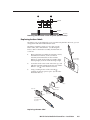
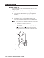
To replace the faceplate,
1.
Hold the MLC face down. Use an Extron Tweeker or a small Philips
screwdriver to remove the three attachment screws (marked a in the
diagram at right) from the back of the MLC, and keep them to replace later.
CAUTION
If installing a metal faceplate, do not remove the screws from the front of
the faceplate.
2.
Lift the MLC off the faceplate.
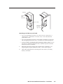
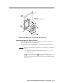
3.
Place the MLC onto the new faceplate, aligning the MLC’s buttons with the
openings in the new faceplate and the three screw holes in the MLC with the
faceplate standoffs.
4.
Replace the three screws removed in step 1, and manually tighten them.
Refer to the MLM 52 1GWP and/or the MLM 52 VC user’s guides for further
information on faceplates for the MLC 52.
1
E
4
3
ON
2
1
+ 12V
GND
IR IN
1 2 3 4
GND
IR OUT
Tx
1
1
Screws to remove from the MLC faceplate
2-4
MLC 52 Series MediaLink Controllers • Installation
MLC 52
Standoff
Faceplate
Installing the MLC onto a new faceplate (bottom view)
Replacing button labels
The button caps are prelabeled for your convenience by default. However, you can
change them with the included button labels.
The button assembly consists of a clear lens cap, the
button label, and a white diffuser. (See the diagram
below.) Remove the button assembly from the MLC 52
as follows:
1.
Remove the button assembly by inserting a small,
flat-bladed screwdriver, such as an Extron
Tweeker, between the button’s base and the
diffuser to gently pry the button assembly off the
button plunger, as shown in the drawing at right.
2.
Locate the small corner notch on the lens cap, and
slide the screwdriver between the lens cap and the
diffuser. (See b in the illustration below.)
3.
Using a rotating motion of the screwdriver,
carefully pry the two pieces apart. (See c in the
illustration below.)
Pry the button
from the base.
Plunger
Base
TE
XT
Diffuser
Clear Lens
3
Button Label
Pry the two
pieces apart.
2
Notch
Separate the twopiece button here at
the corner.
Replacing a button label
MLC 52 Series MediaLink Controllers • Installation
2-5
Installation, cont’d
4.
Lift out the transparent square label that you want to replace, being careful
not to damage the circuits beneath it. You may need to use the small
screwdriver to gently pry the label out.
5.
Detach one of the preprinted labels or one of the blank labels from the label
sheets included with the MLC 52. Remove the label from the backing and, if
applicable, peel the protective film from the front of the label.
If you want to create customized labels, you can use a label maker, such as the
Brother® P-touch®, and clear label material to print text to place on the blank
labels. Cut the labels so that they are square and measure ½ inch on each edge.
6.
Insert the new label into the clear button cap, align the white backing plate
with the cap, and firmly snap it into place.
7.
Gently, but firmly, press the reassembled button into place on the MLC 52
front panel.
8.
Repeat steps 1 through 7 as needed to relabel other buttons.
Mounting an electrical box
If you want to install the MLC 52 in an electrical box (in a wall or in furniture),
1.
Refer to the appropriate template diagram in appendix B, “Dimensions and
Templates,” to find out the dimensions of the opening required for the size of
the wall box that you are using. If you are using a mud ring with the wall
box, refer to the templates provided with the bracket.
2.
Using a ruler or tape measure and a soft pencil, draw guidelines on the
installation surface (wall or furniture) in the desired orientation and location
where the opening for the bracket or wall box will be cut.
CAUTION
The template diagrams in this guide are not to scale. Do not trace
them or use them as patterns on the installation surface. Use these
diagrams only for reference to obtain the dimensions of the hole that needs
to be cut. Use a ruler to measure and draw the cutting guidelines.
3.
Cut out the wall or furniture material inside the marked area.
4.
Check the opening size by inserting the wall box or mounting bracket into the
opening. The equipment should fit easily into the opening. Enlarge or
smooth the edges of the opening if needed.
5.
Feed cables through the wall box punch-out holes, and secure them with cable
clamps to provide strain relief.
6.
Exposed cable shields (braids or foil) are potential sources of short circuits.
Trim back and/or insulate shields with heat shrink.
To prevent short circuits, you can cut back the outer foil shield to the point
where the cable exits the cable clamp. Both braided and foil shields should
be connected to an equipment ground at the other end of the cable.
7.
2-6
Insert the wall box into the opening, and attach it to the wall stud or furniture
with nails or screws, leaving the front edge flush with the outer wall or
furniture surface. The following illustration applies to all sizes of wall boxes.
MLC 52 Series MediaLink Controllers • Installation
Wall Stud
Installation
Cable
Cable Clamp
Screws or Nails
Wall opening
flush with
edge of box
Attaching a wall box to a wall stud
•
If you are attaching the wall box to wood, use four #8 or #10 screws or
10-penny nails. A minimum of ½ inch (1.3 cm) of screw threads must
penetrate the wood.
•
If you are attaching the wall box to metal studs or furniture, use four #8 or
#10 self-tapping sheet metal screws or machine bolts with matching nuts.
•
If you are using a mounting bracket (mud ring) with the wall box, follow
the directions included with the bracket to attach the clips that fasten the
bracket to the wall or furniture.
8.
If desired, replace the faceplate and/or button labels on the MLC. (See
“Replacing the Faceplate and Button Labels,” earlier in this chapter.)
9.
Cable and test the MLC before fastening it into the wall box, mounting
bracket, or furniture.
MLC 52 Series MediaLink Controllers • Installation
2-7
Installation, cont’d
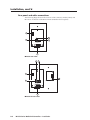
Rear panel and cable connections
The following diagrams show the locations of the connector, switches, LEDs, and
IR sensors on the back of the MLC 52 with standard and VC faceplates.
1
2
E
4
3
6
ON
2
1 2 3 4
3
IR OUT
GND
IR IN
GND
+ 12V
Tx
1
5
MLC 52 rear view
2
3
1
VOL/
MUTE
+ 10V
4
E
4
3
6
ON
2
+ 12V
GND
IR IN
1 2 3 4
GND
IR OUT
Tx
1
5
MLC 52 VC rear view
2-8
MLC 52 Series MediaLink Controllers • Installation
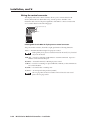
1
IR learner/transmitter — These sensors allow for IR control of the MLC and
for IR learning. The two LEDs (one for transmitting, one for receiving) send
and receive IR signals, enabling the MLC to learn commands and clone
configurations from another MLC. The IR remote control must be pointed
directly at these LEDs for best results.
The MLC can “learn” IR commands in order to control the display device. IR
learning of device control codes is necessary only if there are no RS-232 codes
available for that device or if you need to customize the driver. The IR
learning procedure is discussed in the “Configuring using IR learning”
section of chapter 3, “Operations.”
You can also perform IR learning via the Windows-based configuration
software. See “Performing IR learning via software,” in chapter 5, “Serial
Communication.”
2
Enable Macro LED — The LED located immediately above the four green IR
LEDs is labeled E, for Enable Macro. This LED lights amber when you place a
button in macro mode. (See “Setting up macros,” in chapter 3, “Operations.”)
3
Configuration switches — When set to “on,” these DIP switches place the
MLC in IR learning mode or data transfer mode, or disable IR repeats.
•
Switch 1: Enables IR learning.
•
Switch 2: Enables data transfer, such as cloning the MLC’s configuration
onto another MLC 52 (see “Configuring using IR data transfer,” in
chapter 3, “Operations”).
•
Switch 3: Disables IR repeats during playback. For most applications,
this switch is placed in the off position.
Switch 4 is not used.
4
Volume control (VC faceplate only) connector — Connect this volume
control connector to an amplifier such as the Extron MPA 122 or MPA 181T to
enable the volume control knob on the MLC 52 to raise and lower the volume
on the display device via the amplifier.
5
Display control and power connector — This six-pole, 3.5 mm captive screw
connector is used for IR and RS-232 control of the display device and for DC
power. (See “Wiring the control connector,” in the next section, for
information on how to connect supported devices to the MLC.)
The RS-232 projector control port is present on this connector but not
functional on the IR models. This port is functional only on the RS models.
6
IR learning indicators — Each button on the MLC front panel has four
memory blocks, which can be programmed with up to four IR (or RS-232)
commands. The IR learning indicator LEDs provide visual feedback
indicating the following:
•
Which of the four memory blocks contains a command
•
Which of the four memory blocks is ready to be programmed or
configured
•
The IR learning status of the controller
See “Configuring for IR learning,” in chapter 3, “Operation,” for details.
MLC 52 Series MediaLink Controllers • Installation
2-9
Installation, cont’d
Wiring the control connector
The display and source control connector allows you to connect cables for IR
devices, RS-232 devices (RS models only), and AC power to the MLC. The
illustration below shows the pin assignments of the MLC’s control connector that
are covered in detail on the following pages.
RS-232 Tx (RS models only)
IR out
IR in
12 V DC in
F E D C B A
Pinout guide for the MLC 52 display/source control connector
The ports in this connector, from left to right, perform the following functions:
F (Tx) — Transmits the RS-232 signal for projector control.
Although this port is present on both the IR and the RS models, it is functional
only on the RS models.
E (IR out) — Used for connecting an IR emitter to issue IR commands. Up to two
emitters can be wired to this port.
D (GND) — Ground for IR and/or RS-232 projector control
C (IR in) — Used for connecting an optional IR Link or IRL 20, so that an IR remote
can control the MLC.
B (GND) — Ground for the +12 VDC power
A (+12 V) — Power input for the product (12 VDC)
The two-gang MLC 52 IR VC and MLC 52 RS VC have the same control
ports as the one-gang models.
2-10
MLC 52 Series MediaLink Controllers • Installation
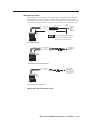
Wiring for IR control
If you intend to control display and/or input devices via infrared (IR) commands
from the MLC, you can connect Extron IR emitters or an IR Broadcaster to the
IR Out pin of the control connector. Up to two IR emitters can be connected via this
connector at one time. Wire the connector as shown in the following illustrations.
White striped wire only
E
D
Modulated IR
Ground
100 feet (30.5 m) maximum
MLC 52
control
connector
IR
Emitter
Connect up
to 2 IR
Emitters
(max.)
(#70-283-01).
Place the head of each IR Emitter
over or directly adjacent to the
controlled device’s IR receiver.
F E D C B A
IR
For the IR Emitter only
E Demodulated IR
Ground
D
A +12VDC output
To IR Broadcaster
with Emitter port
(#60-272-02)
MLC 52
control
connector
F E D C B A
IR
For the IR Broadcaster with emitter port
E Demodulated IR
Ground
D
MLC 52
control
connector
To the projector's
wired remote port
(Connector type and
pin configurations may
vary depending on the
projector model.)
F E D C B A
IR
For a wired projector remote port
Wiring the control connector for IR
MLC 52 Series MediaLink Controllers • Installation
2-11
Installation, cont’d
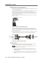
Wiring for RS-232 control (RS models only)
The MLC 52 RS and the MLC 52 RS VC send out RS-232 commands via the Tx port
for controlling a display device.
If you have an RS model and want to control the device via RS-232, connect a cable
between the device and this 3.5 mm, 6-pole direct insertion captive screw
connector. Use the illustration below as a guide to wiring the connector. Wiring
varies depending on the device model. In most cases, only the transmit (Tx) and
ground connections are needed.
Guides for connecting and controlling specific models of devices are available on
the Extron Web site.
RS-232 Tx (RS models only)
IR out
IR in
12 V DC in
F E D C B A
Wiring for RS-232 control (RS models only)
Extron recommends using the UC 50' universal projector control cable for this
connection. One end of the cable is terminated with a female 9-pin D connector,
and the other end is unterminated. The UC 50' cable pin assignments are as shown
in the following illustration.
Refer to the display device user’s manual for the device’s pin assignments in order
to determine which of the cable’s wires to connect to the MLC’s RS-232 pins.
To the
MLC 52
Black
Grey
Purple
Blue
Green
Yellow
Orange
Red
Brown
9
8
7
6
5
4
3
2
1
1
5
UC Cable
Shield
Color Pin #
6
9
To the
display
device
Connector Shell
UC 50', 100', and 200' cable color codes
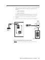
Wiring an IR Link
An optional IR Link or IRL 20 can be connected to the IR In pole of the control
connector to enable the MLC to receive IR signals from the IR 452.
Only one IR Link or one IRL 20 can be attached to the MLC 52 at one time.
To wire the IR Link for use with your MLC,
2-12
1.
Prepare the site where the IR Link will be installed and install a wall box,
following the directions in the IR Link User’s Manual, provided with your
IR Link equipment.
2.
Cut the required length of Extron CTL (Comm-Link) cable to go between the
MLC 52 and the IR Link. The power cable length should not exceed 150'
(45.7 m).
MLC 52 Series MediaLink Controllers • Installation
Attach a 3.5 mm, 5-pole captive screw connector to one end of the cable and a
6-pole captive screw connector to the other end. Only three wires are
required:
3.
•
A (MLC) to A (IR Link)
•
B (MLC) to B (IR Link)
•
C (MLC) to D (IR Link)
Connect the wires as shown in the illustration below. Connectors are
included with the IR Link, but the cable must be purchased separately.
4.
Plug the 5-pole connector into one of the IR Link’s communications
connectors.
5.
Plug the 6-pole connector into the rear panel control port of the MLC 52.
IR Link
IR Signal
Repeater
C Modulated IR D
B Ground ( ) B
A
A +12VDC
40
DVD
FRONT PANEL
TV/VCR
PC
CHANNEL
VIDEO
IR 452
SYSTEM REMOTE
IR in
VOL
VOL
VCR
DVD
VCR
ABCDE
IR 452 Remote
Control
30’ (12 m)
max.
40
SIGNAL
SIGNAL
IR
IRLINK
LINK
Total distance
from MLC is
150' (45.7 m) max.
F E D C B A
MLC 52
Control
Port
DISPLAY
ON
VOL
VOL
OFF
PC
VIDEO
IR Link
MLC 52
MLC 52 or MLC 52 VC
Wiring and using the IR Link for IR remote control
Do not connect more than one IR Link, either in parallel or in series.
MLC 52 Series MediaLink Controllers • Installation
2-13
Installation, cont’d
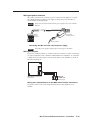
Wiring an IRL 20
The Extron IRL 20 is a hardwired IR signal receiver that can be used with the
MLC 52 and the IR 452 remote control. The IRL 20 receives a signal via its front
panel (or an IR sensor) from the IR 452 remote control, and outputs a modulated IR
signal via an IR emitter or an IR Broadcaster.
SIG
+5V
SCP
IR SNSR
GND
CM
ModIR
GND
SCP
+12V
CM
ModIR
+12V
GND
+ 12V
GND
IR IN
GND
IR OUT
Tx
C Modulated IR D
B
GND
B
A
A
+12 V
IRL 20
Control Connector
for MLC 52 Series
(Rear Panel)
+12 VDC A
Ground ( ) B
External Power Supply
(12 VDC, 1A max.)
Wiring an IRL 20
Wire and connect the IRL 20 to the MLC 52 as follows:
1.
If it has not been done, cut the required length of Extron CTL (Comm-Link)
cable to go between the MLC 52 and the IRL 20. See appendix A,
“Specifications, Part Numbers, and Accessories,” for cable part numbers.
The maximum total distance between an Extron controller and the IRL 20 is
150' (45.7 m).
2.
Attach a 3.5 mm, 5-pole captive screw connector to the end of the cable that
will be plugged into the IRL 20.
3.
Connect the wires on the other end of the cable to the provided 3.5 mm 6-pole
captive screw connector.
•
A (MLC) to A (IR Link)
•
B (MLC) to B (IR Link)
•
C (MLC) to D (IR Link)
Do not connect more than one IRL 20 or IR Link (either in parallel or in series)
to an Extron device.
4.
Plug the 5-pole connector end of the cable into one of the IRL 20’s
communications connectors.
5.
Plug the 6-pole connector end of the cable into the control port on the MLC 52
back panel.
6.
Connect power to the MLC or the IRL 20.
+12 VDC power is shared between the MLC 52 and the IRL 20 when they are
connected. You can wire the power supply to either the MLC or the IRL 20.
2-14
MLC 52 Series MediaLink Controllers • Installation
Wiring the power connector
The control connector also contains a power connector for the MLC 52. Connect
the supplied external 12 VDC power supply to this port to power the MLC as
shown in the following diagram.
The Extron P/S 100 and other Extron power supplies can be used with the
MLC 52.
B Ground ( )
A +12 VDC input
External
Power Supply
(12 VDC, 1A max.)
MLC 52
Control
Connector
F E D C B A
Ground all devices.
Connecting the MLC 52 to the external power supply
Check the power supply’s polarity before connecting it to the MLC.
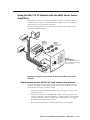
Wiring the VC port
If you have an MLC 52 IR VC or an MLC 52 RS VC controller, it can be connected to
an optional amplifier, such as the Extron MPA Mini Power Amplifier. To set up this
configuration, wire the volume control potentiometer to the amplifier as shown in
the following diagram.
VOL/
MUTE
10V
VOL
10V
MLC 52 VC Potentiometer
Rear Panel
1
2
10V VOL
3
MPA 122
or MPA 181T
Remote Port
Wiring the VC potentiometer to the MPA remote volume control port
Set up the volume control, following the instructions in the amplifier’s user
manual.
MLC 52 Series MediaLink Controllers • Installation
2-15
Installation, cont’d
Mounting the MLC 52
Once the system has been cabled, configured, and tested, the MLC can be installed
in the wall or furniture.
Mounting the MLC to an electrical box or mounting bracket
You can mount the MLC 52 in an electrical box or a mounting bracket, as follows:
1.
If you want to install a different faceplate, attach the MLC to the desired
faceplate using the provided screws. (See “Replacing the faceplate,” earlier in
this chapter.)
2.
Connect all cables to the MLC, and disconnect power at the source.
3.
Insert the MLC into the wall or furniture.
4.
Secure the MLC to the wall box or mounting bracket with the provided
machine screws (as shown in the following illustrations), or attach it directly
to the furniture with wood or metal screws.
If the MLC (and the IR Link, if applicable) is not mounted to a grounded metal
wall box,
•
Ground each faceplate directly to an earth ground, or
•
Tie each faceplate to its circuit board and power supply via a ground pin on
one of the connectors.
Do not tie a product’s faceplate to both a separate earth ground and the circuit
ground (via a connector pin). If you tie a product to two different ground
sources, you may introduce ground loops or other grounding-related problems
into the system.
AY
PL
DIS
F
OF
ON
Wall opening
is flush with
edge of box.
PC
L
VO
VID
EO
L
VO
2
C5
ML
MLC 52
Mounting the MLC 52 in a wall box
2-16
MLC 52 Series MediaLink Controllers • Installation
Wall
Extron
Wall Mounting Bracket
AY
PL
DIS
OF
F
ON
PC
L
VO
VID
EO
L
VO
2
C5
ML
MLC 52
Mounting the MLC 52 to a mounting bracket (mud ring)
Mounting the MLC to a wall or furniture
1.
With all cables attached to the MLC and power disconnected at the source,
insert the MLC into the wall or furniture.
2.
Fasten the MLC and faceplate directly to the furniture or wall using wood
screws.
If the MLC (and the IR Link, if applicable) is not mounted to a grounded metal
wall box,
• Ground each faceplate directly to an earth ground, or
• Tie each faceplate to its circuit board and power supply via a ground pin on
one of the connectors.
Do not tie a product’s faceplate to both a separate earth ground and the circuit
ground (via a connector pin). If you tie a product to two different ground
sources, you may introduce ground loops or other grounding-related problems
into the system.
MLC 52 Series MediaLink Controllers • Installation
2-17
Installation, cont’d
2-18
MLC 52 Series MediaLink Controllers • Installation
MLC 52 Series
3
Chapter Three
Operation
Display Device Control
Front Panel Features and Operation
Configuring the MLC 52 Using IR
Using the MLC 52 VC Models with the MPA Series Power Amplifiers
Powering the Display Device On and Off
Selecting Inputs
Operating the MLC 52 Using IR Remote Control
Resetting
Locking the Front Panel (Executive Mode)
Operation
Display Device Control
The MLC 52 IR models can control a projector or other display device by using
infrared (IR) signals. The RS models can control a display device using IR or
RS-232. The MLC must be configured for device control by one of the following
methods before it will send commands to the display device:
•
An IR or an RS-232 driver file can be loaded from a disk or the Extron Web
site and used to configure the MLC.
•
RS-232 and IR commands can be added to the MLC buttons from a host
computer using the supplied Windows-based configuration software. See
chapter 5, “Serial Communication,” and the Windows-based configuration
software help file for details on setting up the MLC and for downloading,
programming, or learning device control commands using the software.
•
IR commands can be entered directly from an IR remote control into the MLC
through IR learning. IR learning is convenient for installing new or updated
commands into the MLC in the field. It can be performed with or without the
use of software.
•
An MLC 52 can transfer/configure (duplicate or clone its configuration) to
another MLC 52 via IR data transfer without the use of cables or software.
Each time a new device driver is used to configure the MLC, previous
configurations are replaced (overwritten) by the new driver. Configurations are
stored in nonvolatile memory. Therefore, if the power to the unit is interrupted, the
MLC retains its settings and configuration.
Front Panel Features and Operation
The MLC 52 front panel contains six buttons, each of which can be programmed
with up to four IR or RS-232 commands/functions. It also contains a configuration
port, through which the MLC 52 can be connected to a PC’s RS-232 port to program
the MLC’s buttons, update firmware, and save the MLC’s current configuration to
the PC’s hard drive.
The two-gang sized MLC 52 IR VC and MLC 52 RS VC each have an integrated
volume control knob. On these models, the two buttons normally used for volume
control on the standard, one-gang MLC can be used to control additional outputs
or other projector or display functions.
Buttons on the front panel
The front panel backlit buttons light amber when the MLC 52 is powered on.
Buttons that are not currently selected and active are lit more dimly (25%
brightness) than the selected ones (100% brightness).
When the MLC is delivered, the buttons are labeled. (You can relabel them by
replacing the labels with others provided with the MLC. See “Replacing button
labels” in chapter 2, “Installation.”) You can program commands onto these
buttons (up to four commands per button) using IR learning, the Windows-based
configuration software via the configuration port, or IR data transfer from a
configured MLC 52.
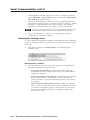
Switch modes
Depending on the driver that you load to your MLC, each of the controller’s
buttons is preconfigured in one of the following switch modes:
•
3-2
Single switch mode: In this mode, the button operates independently of the
other buttons. Pressing a button in this mode does not affect any other
button.
MLC 52 Series MediaLink Controllers • Operation
•
Input mode: Buttons in this mode are grouped together so that only one of
them can be active at a time. When one button is pressed and activated, it
becomes fully lit, while the other (inactive) button(s) are dimmed to 25%
brightness. When you press one of the buttons on the front panel that are in
input mode, all other buttons in input mode become inactive.
•
Volume mode: This mode is available only on the standard (not VC) MLC
model, and only for the two buttons that are labeled Vol > and Vol <. When
an RS-232 driver that contains a volume table is part of the configuration,
pressing a button in volume mode accesses the driver’s volume table. Each
press of the button raises or lowers the volume of the display device by the
amount specified in the volume table. When in volume mode, the button
labeled Vol > always increases the volume; Vol < lowers it.
•
Power mode: The two Display buttons at the top of the front panel, labeled
On and Off, are permanently fixed in power mode. This mode is similar to
input mode. The two Display buttons are mutually exclusive; if you press
one, the other one becomes unlit.
If you want to change the switch mode of any button, you must use the Windowsbased configuration software. (See “Setting up button modes and labels” in
chapter 5, “Serial Communication,” for the procedure.)
Front panel components
The diagrams below show the front panel features of the standard one-gang
MLC 52 and of the two-gang MLC 52 VC.
5
DISPLAY
ON
DISPLAY
1
OFF
VOLUME
PC
VOL
4
ON
OFF
VCR
PC
2
VOL
VIDEO
1
2
DVD
MLC 52
MLC 52
3
3
MLC 52 IR and RS
MLC 52 IR VC and RS VC
MLC 52 front panel
1
Display power buttons — The display power buttons turn power to the
projector or plasma display on and off. Because the display device can be
only on or off at a given time, these buttons are programmed in an exclusive
switch group. (A 2-second hold requirement can be enabled or disabled via
the configuration software; see “Entering display device power settings” in
chapter 5, “Serial Communication.”)
MLC 52 Series MediaLink Controllers • Operation
3-3
Operation, cont’d
2
Input selection buttons — These buttons are preprogrammed to select input
sources. By default, they are in input mode; that is, only one of them may be
selected at a time. If you want these buttons to operate independently of
each other, use the Windows-based control software to remove the group
configuration from them.
The input buttons are prelabeled for convenience. You can relabel them using
the other labels that are provided. See “Replacing button labels” in chapter 2,
“Installation,” for the relabeling procedure.
3
Configuration port — This port is used for configuring and communicating
with the MLC. Through this port, the MLC receives commands issued via
the Windows-based configuration software on your computer.
Use a 2.5 mm TRS to 9-pin D-sub connector cable to connect the MLC to your
PC via this 2.5 mm female TRS connector.
This cable is an optional accessory that can be ordered from Extron (part
#70-335-01)
The protocol for this configuration port is as follows:
•
•
•
•
1
9600 bits/second
8 data bits
1 stop bit
No parity
6
9
5
Tip
Ring
Sleeve (Gnd)
9-pin D
Connection
TRS Plug
Pin 2
Pin 3
Pin 5
Computer's RX line
Computer's TX line
Computer's signal ground
Tip
Ring
Sleeve
2.5 mm connector cable for the configuration port
See chapter 5, “Serial Communication,” for details about using the
configuration software to set up the system, and about downloading drivers.
4
Volume adjustment buttons — (Standard MLC 52 IR and MLC 52 RS only)
These two buttons are used to adjust the volume of the projector or display up
and down.
If your A/V system does not require the volume up and down function (for
example, if the MLC is configured with the VC faceplate containing the
volume control knob), you can reprogram these buttons for input selection or
additional display device functions.
The volume buttons are prelabeled for convenience. They can be changed to
other labels that are provided. See “Replacing button labels” in chapter 2,
“Installation,” for the procedure.
5
3-4
Volume control knob — (MLC 52 IR VC and MLC 52 RS VC only) The
volume control knob on the VC models enables you to adjust the volume of
the display device via the MPA or other power amplifier.
MLC 52 Series MediaLink Controllers • Operation
Configuring the MLC 52 Using IR
The MLC 52 can be programmed/configured via IR by the following methods:
•
IR data transfer from an MLC 52 that has been configured
•
IR learning from your projector’s remote control
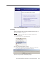
Configuring using IR data transfer
You can configure your MLC 52 by transferring button configuration data to it from
another configured MLC 52 via the two IR LEDs on the back panels of the MLCs.
With this method, you replicate (clone) the other MLC’s configuration on your own
unit without the use of software or cables.
The following transfers are allowed:
•
From an RS model to another RS model
•
From an IR model to another IR model
•
From an IR model to an RS model
To transmit configuration data via IR, both the transferring and the receiving MLCs
must be free of the wall, electrical box, or furniture, and both must be powered on.
The MLC that is already configured can be powered by an external power supply,
or it can share a power supply with the unit that will be configured.
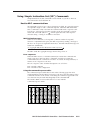
All four MLC 52 models use the same IR data transfer
procedure.
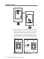
1.
2.
On the MLC from which the configuration will be transferred
(the donor unit), set all configuration switches to Off (down).
On the MLC that will receive the data, set switch #2 to On (up)
and all the other switches to Off (down).
ON
1 2 3 4
Transmitting MLC
ON
1 2 3 4
Receiving MLC
3.
Position the two units so that the IR Transmit and Receive LEDs of both MLCs
are facing each other, and no more than 6 inches apart. (See the illustration on
the next page.)
MLC 52 Series MediaLink Controllers • Operation
3-5
Operation, cont’d
Tx
IR OUT
1
GND
IR IN
GND
+ 12V
Less Than 6”
1 2 3 4
2
3
ON
4
E
E
4
3
IR Beaming
ON
2
+ 12V
GND
IR IN
1 2 3 4
GND
IR OUT
Tx
1
ON
1 2 3 4
Transmitting MLC
ON
1 2 3 4
Receiving MLC
Setting up transmitting and receiving units for wireless data transfer
The data transfer begins when the receiving unit detects the transmitting unit,
and the process takes 15 to 20 seconds to complete. (It may take longer if the
transmitting unit has multiple commands programmed on each button.)
The front panel buttons act as data transfer progress indicators. While data is
being transferred, the buttons on both the transmitting and the receiving
MLCs blink sequentially in clockwise order, starting with the On button in the
upper-left corner (see the diagram below). This cycle repeats until transfer is
complete.
DISPLAY
DISPLAY
ON
VOL
OFF
VOLUME
ON
PC
VCR
VOL
VIDEO
MLC 52
Order in which the buttons blink during data transfer
3-6
OFF
MLC 52 Series MediaLink Controllers • Operation
PC
DVD
MLC 52
After approximately 17% of the data has been transferred, the On button
lights and remains lit to maximum brightness. After another 17% has been
transferred, the Off button lights to maximum brightness. The buttons
continue to light brightly in clockwise order after each increment of 17% of
the data has been transferred. When a button becomes permanently lit, the
remaining buttons continue to blink in clockwise rotation, until the transfer
process is complete and all buttons are remain steadily lit.
The following table shows how each percentage of transferred data is
indicated by button lighting:
Percent Complete
MLC 52
Buttons Lit
MLC 52 VC Models
Buttons Lit
Less than 17%
On
On
18% to 36%
Off
Off
37% to 54%
PC
PC
55% to 72
Video
(blank)
73% to 90%
Vol <
DVD
90% to 100%
Vol >
VCR
When the transfer is complete, all buttons on each unit remain brightly lit
until a button is pressed on the unit.
If the transmission is interrupted (for example, the two units
become separated so that the IR LEDs are no longer in direct line
of sight of each other), and the conditions necessary for transfer are
then restored, the two units restart the transfer process.
4.
When the data transfer is complete, do either of the following:
•
If you are finished performing data transfers, return configuration
switch #2 on the receiving MLC to the off (down) position. Press any
button on both units to return them to the state they were in before the
transfer. All buttons dim except for those that were bright previously.
Reinitialize the receiving unit by pressing any of its front panel buttons.
•
If you want to repeat the transfer process to configure another MLC 52,
repeat steps 2 and 3 for the unit that is to be configured. Press any button
on the donor unit. The transfer process restarts.
Configuring using IR learning
You can also configure the MLC 52 by using IR learning, which does not require
configuration software. By this method, you can program the functions on your
display device’s remote control onto the buttons on the MLC front panel. This
procedure must be performed before the MLC is mounted on a wall or furniture, so
that the IR Transmit/Receive LEDs are accessible.
To program the MLC via IR learning,
1.
Apply power to the MLC 52.
2.
On the rear panel, set configuration switch #1 to On (up). All
front panel buttons should be dimly lit.
ON
1 2 3 4
MLC 52 Series MediaLink Controllers • Operation
3-7
Operation, cont’d
3.
Press the button on the MLC that will store the IR code that you want the
MLC to learn. The following takes place on the MLC:
•
The front panel button that you pressed begins to blink, indicating that it
is ready to be programmed. While the button is blinking (5 seconds), you
can program it with the desired command. If no IR command is entered
within 5 seconds, the button stops blinking.
•
On the rear panel, the IR learning LED for the next button memory block
available for programming begins to blink. (See “IR learning indicators,”
f in the “Rear panel/cable connections” section of chapter 2,
“Installation,” for more information on the IR learning LEDs.)
•
The LED that indicates how many commands have been programmed
onto the button illuminates and remains lit.
E
E
E
E
LED Off
4
4
4
4
LED Blinking
3
3
3
3
2
2
2
2
1
1
1
1
LED On
Command 1 is ready
to be learned.
Command 2 is ready
to be learned.
Command 1 was learned.
Command 3 is ready
to be learned.
Command 2 was learned.
Command 1 was learned.
Command 4 is ready
to be learned.
Command 3 was learned.
Command 2 was learned.
Command 1 was learned.
Activation of LEDs during button configuring
4.
Hold the display device’s remote control 4 to 14 inches (10 to 36 cm) away
from the MLC and point it at the MLC’s IR Transmit/Receive LEDs. Within
5 seconds of pressing the MLC button (step 3), press the button on the
remote whose function you want the selected MLC button to learn. When the
IR command has been learned successfully, the IR learning LEDs blink in
rapid progression from the top to the bottom, then back to the top.
For repeating command codes, such as those that increment/decrement a
function (for example, turning the volume up and down), hold the button on
the projector remote control for at least 3 seconds.
If no IR command is detected within 5 seconds, the LEDs and the front panel
button time out and stop blinking.
5.
•
If the IR code was learned, the rear panel LEDs blink rapidly in
succession from the top down, then back up to the top.
•
If the IR code was not learned, the rear panel LEDs blink in random
order.
If you want to program another command to the same button (you can
program up to four commands on one button), press the button again. The
next IR learning LED on the rear panel begins flashing (for example, if you
have already programmed two commands on this button, the third LED from
the bottom flashes).
If you do not want to program additional commands on the button, repeat
steps 3 and 4 for the next button that you want to program.
6.
3-8
When you are finished programming buttons on the MLC, set configuration
switch #1 on the rear panel to Off (down).
MLC 52 Series MediaLink Controllers • Operation
7.
Press the buttons that you configured to verify that the commands you
entered have been learned. If you have an IR Emitter connected on the IR
output, it should blink. (See “Wiring for IR control” in chapter 2,
“Installation.”)
Removing commands from a button
If you want to delete a command that has been programmed onto a button, you
must remove all the commands programmed to that button, as follows:
1.
While the MLC 52 is powered on, set configuration switch #1 to On (up).
2.
Press the button for which you want to delete commands, then within
2 seconds press the same button again. The IR learning LEDs turn off.
3.
Verify that the button’s commands were erased by pressing the same button
again. If the commands have been erased, only LED #1 (the bottom LED)
blinks; the other LEDs remain off.
4.
When finished removing commands, set switch #1 to Off (down).
Setting up button macros
Buttons function in either toggle mode or macro mode. By default, all the buttons
(except the On and Off Display buttons) are in toggle mode. This means that each
press of the button issues one command — the next in sequence of the four
commands programmed to the button (each button can store up to four
commands).
In macro mode, a single press of a button issues all the commands (up to four) that
have been programmed on that button, in the order they were programmed, at
1.5-second intervals. An example of a button macro application would be turning
on multiple projectors/displays by pressing one button, one time.
To program a macro for a button,
1.
Ensure that power is applied to the MLC 52.
2.
Set configuration switch #1 on the rear panel to On (up). All front panel
buttons light dimly.
3.
Program the buttons with the desired commands. See “Configuring using IR
data transfer” or “Configuring using IR learning,” earlier in this chapter, for
programming procedures.
You must program the commands onto the button prior to setting it for macro.
4.
To put the button in macro mode, press and hold it for 3 seconds. The orange
LED on the back panel, labeled “E,” flashes rapidly five times, then turns off,
indicating that the button is now configured for macro mode. Release the
button. The next time that the button is pressed while configuration switch #1
is in on position, the orange “E” LED lights, indicating that the button is in
macro mode.
To take a button out of macro mode, press and hold the button for 3 seconds.
The orange “E” LED turns off.
5.
Set configuration switch #1 to Off. Verify that the commands have been
properly learned by pressing the button you programmed. The commands
should be issued in succession at 1.5-second intervals.
A button is able to learn commands while in macro mode if any of its four
command memory blocks are open (not yet programmed with a command).
MLC 52 Series MediaLink Controllers • Operation
3-9
Operation, cont’d
Configuring a single button for input source selection
If you want to use only one button to select your input sources, you must program
the button with one command for each source (up to four). Only one button has to
learn IR commands; and it has enough memory blocks to learn four input selection
commands. To use this programmed button to select an input, you must press it
repeatedly to cycle through all the inputs until you reach the desired one.
To program a single button to select multiple inputs,
3-10
1.
Disconnect power from the MLC 52.
2.
To make the one programmed button easily recognizeable, r eplace all but one
of the input (Video, PC, DVD, and/or VCR) button labels with the provided
Not Used label, or remove the input label(s) and leave the button(s) blank.
3.
Apply power to the MLC.
4.
Set configuration switch #1 to On (up). The front panel buttons light dimly.
5.
Press the MLC button that will store the input selection IR codes. The button
blinks for 5 seconds, during which time it is able to learn codes. On the rear
panel, the first (bottom) IR learning LED starts flashing.) (If a command is not
entered within 5 seconds, the button and LED stop blinking, and you must
press the button again to put it in back in learn mode.)
6.
Within 5 seconds, press the display device remote control button from which
the MLC button will learn the first input selection command. If the command
has been learned successfully, the Learning LEDs on the rear panel blink in
rapid progression from the top LED to the bottom, then back to the top.
7.
To program a second input selection command on the same button, press the
button again. The button and the second rear panel IR learning LED begin to
blink. On your display device’s remote control, press the next button whose
function you want the MLC button to learn.
8.
Repeat the procedure described in steps 5 and 6 for additional commands you
want to add to the button you are programming. Each MLC button can be
programmed with up to four commands.
9.
When finished programming the input selection button, set rear panel DIP
switch #1 to Off (down). Verify that the button has been programmed
correctly by pressing it repeatedly to cycle through the inputs.
MLC 52 Series MediaLink Controllers • Operation
Using the MLC 52 VC Models with the MPA Series Power
Amplifiers
The dedicated volume control knob on the MLC 52 IR VC or the MLC 52 RS VC
controls the audio output of an Extron MPA 122 or MPA 181T power amplifier, to
which speakers for the system are connected.
The following diagram shows an example of a system that uses an MLC 52 VC
model with an MPA amplifier.
PC
VGA with
Audio
DVD
Extron
MPA 122
S-video with
Audio
Extron
SI 26X
Mini Power
Amplifier
Ceiling Speakers
(in parallel)
22
1
A
MP UTS
TP
OU hms
O
4/8
US
UTS
INP
C
REM
R
VCR
L
PO
Composite Video
with Audio
OTE
R
L
E
V
10 L/MUT
VO
L
WER
R
MPA
Volume
Control
DI
Switched
Audio
Output
SP
LA
Y
F
OF
ON
PC
RS-232
Projector Control
V
U
OL
ME
R
VC
TO
AU GE
A
IM
D
DV
ML
2
C5
Extron
MLC 52 RS VC
Basic MediaLink Controller
with IR or RS-232 Hardwired
Projector Control
Projector
Application diagram using an MLC 52 VC with an MPA series power
amplifier
Requirements for the MLC 52 VC with volume control knob
To set up and operate a system that contains an MLC 52 VC model, which has a
volume control knob on the faceplate, and an Extron power amplifier, you must
ensure that the following conditions are met:
•
The projector must have dedicated video and audio inputs for each source
used in the system.
•
The projector must have a switched audio output. On most projectors, this
connector is labeled as “Monitor Output” or “Audio Output,” as shown in the
following illustration. With a switched audio output, the projector outputs
the audio from the selected video source.
•
The system must incorporate an Extron MPA series power amplifier.
MLC 52 Series MediaLink Controllers • Operation
3-11
Operation, cont’d
Wiring and connections for the MLC 52 VC models
Connect the cables to the MLC 52 IR VC or MLC 52 RS VC controller with the MPA
Series amplifier as shown in the diagram below and on page 2-15.
VOL/
MUTE
+ 10V
E
4
3
ON
2
+ 12V
IR IN
1 2 3 4
GND
IR OUT
Tx
1
GND
RS-232 or IR
Projector Control
MLC 52 VC Series
COMPUTER IN-1
Y/C
AV IN
VIDEO
AUDIO
PC
COMPUTER IN-2
AUDIO
AUDIO
R
G
H/Cs
L
Y
R
PB/B-Y
C
B
COMPUTER
OUT
V
PR/R-Y
CONTROL
REMOTE
US
L
REMOTE
R
AUDIO OUT
MPA 122
OUTPUTS
4/8 Ohms
INPUTS
POWER
12V
3A MAX
L
R
10V
VOL/MUTE
L
R
MPA 122
RS-232
To Loudspeakers
Projector
Any input on the MPA
can be used.
Wiring an MLC 52 VC controller and an MPA series power amplifier to a
typical projector
Audio is now controlled from the MPA instead of from the projector. For best
results, ensure that the audio volume of the projector is set to maximum
(assuming that the monitor output for audio is variable).
Configuring the MLC 52 IR and MLC 52 RS Vol buttons
By default, the MLC 52 has two buttons on the front panel programmed for volume
control (Vol > and Vol <). However, on the MLC 52 IR and RS VC models, these
buttons are not needed for volume control and can be programmed for other uses.
To reprogram the Vol buttons, you can use IR learning (see “Configuring using IR
learning,” earlier in this chapter,) or the Windows-based configuration software
(see chapter 5, “Serial Communication”).
Powering the Display Device On and Off
The Display On and Off buttons on the MLC 52 front panel are used to turn the
projector or other display on and off.
Powering on
Press and release the MLC 52’s On button to turn the display device’s power on.
The MLC sends an RS-232 or IR power-on command to the projector, and the On
button blinks for 4 seconds, then remains steadily lit.
3-12
MLC 52 Series MediaLink Controllers • Operation
Powering off
To turn the projector/display off, press the Off button. The button blinks for
4 seconds, then remains steadily lit.
(A 2-second hold feature, requiring you to press and hold the Off button for
2 seconds in order to turn off the display device, helps prevent accidental
powering off of the projector or display. This feature can be disabled and enabled
through the configuration software. See “Entering display device power settings,”
in chapter 5, “Serial Communication,” for further information.)
Selecting Inputs
The four buttons below the Display On and Off buttons on the MLC 52 front panel
can configured to select inputs on the display device. The PC and Video buttons
have been preconfigured to select inputs — the desktop or laptop computer (PC);
the VCR or DVD (Video).
Using IR learning, IR data transfer, or the Windows-based configuration software,
you can reconfigure these buttons and/or add commands to them to select other
inputs if desired. The two volume (Vol) buttons on the standard MLC can be
configured to select inputs as well, if you do not need them to control projector or
display volume. Up to four commands can be programmed on any button. See
“Using the MLC 52 Configuration Program,” in chapter 5, “Serial Communication,”
for information on configuring MLC buttons.
DISPLAY
ON
Input Selection
Buttons
VOL
VOL
OFF
PC
VIDEO
MLC 52
Input selection buttons on the MLC 52 front panel
To select an input, press and release the appropriate input selection button. The
command that was programmed in the button’s first memory block is executed.
•
All buttons are lit at 25% intensity while the MLC receives power. A selected
(active) input button lights more brightly than the other buttons.
•
If there is more than one input selection command programmed in the
button’s memory blocks, you can execute the commands in memory blocks 2,
3, and 4 by pressing the button a second, third, and fourth time.
For example, if you have programmed memory block 1 on the Video button
for a VCR, and memory block 2 for a DVD player, you would press and
release the Video button once to select the input to which the VCR is
connected on the display, then a second time to select the input to which the
DVD player is connected on the display. (Pressing it a third time reselects the
VCR, etc.)
MLC 52 Series MediaLink Controllers • Operation
3-13
Operation, cont’d
•
If an input selection button is in macro mode, pressing the button once
executes all the commands stored on that button, in memory block order (i.e.,
the command in memory block 1 is performed first, then block 2, etc.). See
“Setting up button macros,” earlier in this chapter, for more information.
Operating the MLC 52 Using IR Remote Control
The MLC 52’s optional hand-held IR 452 remote control can be used in conjunction
with the MLC 52 to operate your projector, plasma display, and input devices. The
IR 452 remote control is delivered with commands for a variety of device functions
(for example, VCR On, VCR Off, Stop, Pause). These commands can be
programmed onto the MLC’s buttons only via the Windows-based configuration
software. (See “Assigning functions to buttons” in chapter 5, “Serial
Communication.”
The IR 452 cannot perform the volume knob’s function on the MLC 52 IR VC
or the MLC 52 RS VC. All other functions on the IR 452 are available on the
MLC 52 VC models.
The IR 452 remote control also requires the optional IR Link or IRL 20 in order to
send commands to the MLC, which in turn issues the commands to the input or
output devices.
1.
Wire the IR Link or IRL 20 to the MLC 52 and mount it. (See “Wiring for IR
remote control” or “Wiring the IRL 20,” in chapter 2, for IR Link or IRL 20
wiring instructions. See the IR Link or the IRL 20 user’s guide for mounting
instructions.)
2.
Using the MLC 52 Windows-based configuration software, program the
desired buttons on the IR 452 with the commands available with the currently
loaded driver.
(See “Assigning functions to buttons” in chapter 5, “Serial Communication,”
for button programming instructions.)
3.
40
VOL
VOL
VCR
FRONT PANEL
DVD
PC
TV/VCR
VIDEO
CHANNEL
The remote control sends
the pressed button’s
programmed command
via infrared (IR) signal to
the IR Link or IRL 20.
The IR Link or IRL 20
sends the command to the
MLC through the MLC’s
IR IN pole on the control
connector, to which the
IR Link or IRL 20 is connected.
MLC 52 Series MediaLink Controllers • Operation
DVD
•
IR 452
SYSTEM REMOTE
IR 452 Remote
Control
Press the button for the
function you want to perform.
The following takes place:
•
3-14
IR Link
IR Signal
Repeater
VCR
4.
To operate a device using the
IR 452, point the remote
control directly at the IR Link
or IRL 20 signal pickup
window. The IR 452 has a
range of approximately 30'
(12 m) within 40 degrees on
either side of the axis (see the
illustration at right).
30’ (12 m)
max.
40
SIGNAL
SIGNAL
IR
IRLINK
LINK
Total distance
from MLC is
150' (45.7 m) max.
DISPLAY
ON
VOL
VOL
OFF
PC
VIDEO
MLC 52
MLC 52 or MLC 52 VC
Using the IR Link with the
MLC 52 and the IR 452
•
The MLC recognizes the command it receives via the IR IN pole, and
responds as if its own equivalent button were pressed, issuing the
command to the appropriate device.
See “Wiring an IR Link” in chapter 2, “Installation,” for information on wiring the
IR Link. See “Wiring the IRL 20,” also in chapter 2, for information on connecting
the IRL 20 signal receiver.
Setup operations cannot be performed from the IR 452 remote control.
Buttons on the IR 452 remote control
The buttons on the optional IR 452 Remote
Control duplicate the MLC 52’s front panel
controls for normal operation. The MLC
responds to commands from the IR 452 as if
the corresponding button were pressed on the
controller.
From a distance of no more than 30 feet and
within 40 degrees of the axis, the IR 452 sends
infrared (IR) signals to an MLC 52 via the
optional IR Link or IRL 20.
MLC 52 configuration cannot be
performed from the IR 452.
The IR 452’s Display Power On and Power Off
buttons and the VCR and DVD control
buttons cannot control a device through the
MLC until commands have been stored in the
MLC’s memory. The IR 452’s VCR buttons
control the first (lowest address numbered)
VCR connected to the MLC, while the DVD
buttons control the first (lowest address
numbered) DVD connected to the MLC.
The IR 452 cannot control the volume
knob function on the MLC 52 IR VC
or the MLC 52 RS VC. All other
functions on the IR 452 are available
on the MLC 52 VC models.
Commands are transmitted from the MLC’s
control connector (via hard wiring) and IR
ports (via IR Emitters or the optional
IR Broadcaster) when the corresponding
button is pressed on the IR 452 or on the
controller’s front panel.
TV/VCR
CHANNEL
FRONT PANEL
VOL
PC
VOL
VIDEO
DVD
DVD
VCR
VCR
IR 452
SYSTEM REMOTE
MLC 52 Series MediaLink Controllers • Operation
3-15
Operation, cont’d
Resetting
In the event that the MLC 52 needs to be reset, you can do so by one of the
following methods:
Factory firmware reset — Press and hold the bottom right button (the Video button
on standard models or the blank button on VC models) while applying power
to the MLC. This method resets the MLC firmware to the version with which
the unit was delivered from the factory. Any codes that you previously
programmed for the buttons remain in effect.
Factory configuration reset — Press and hold the On and Off (Display) buttons
simultaneously while applying power to the MLC. This method removes all
codes from the buttons.
You can also reset the MLC to its factory defaults via the Windows-based
configuration software. See “Resetting” in chapter 5, “Serial Communication.”
Locking the Front Panel (Executive Mode)
To prevent access by unauthorized users, or accidental presses of the button
issuing unwanted commands to devices, the front panel controls can be locked
using executive mode. When the MLC 52 is in executive mode, all front panel
functions are locked, so that pressing the buttons has no effect.
If a button is pressed while the MLC 52 is in executive mode, all the front panel
buttons blink, indicating that the front panel is locked.
To place the MLC in executive mode,
1.
Power off the display device. Executive mode cannot be enabled if the device
is on.
2.
On the standard MLC 52 models, press and hold the Vol > and Video buttons
simultaneously for 5 seconds.
On the VC models, press and hold the unlabeled button (bottom right) and
the VCR button simultaneously for 5 seconds.
DISPLAY
ON
VOL
VOL
DISPLAY
OFF
ON
OFF
PC
VCR
PC
VIDEO
DVD
VOLUME
MLC 52
MLC 52
Buttons to press and hold for executive mode
When the MLC enters executive mode, all front panel buttons flash three times,
then return to their original state.
To exit executive mode, press the same two buttons again, holding them for
5 seconds.
3-16
MLC 52 Series MediaLink Controllers • Operation
MLC 52 Series
4
Chapter Four
Special Applications
Application 1: Using Multiple Sources with an MLC 52
Application 2: Controlling Projectors that Require Power Off Confirmation
Application 3: Controlling Projectors That Have Multi-coded IR Functionality
Special Applications
This chapter describes some special types of applications that represent unique
conditions. For the MLC 52 to operate properly in these situations, it is important
that the controller be configured correctly. On the following pages, three
application examples are described, along with their requirements for the MLC 52.
Application 1: Using Multiple Sources with an MLC 52
Following is an example of an application in which the system contains more than
two inputs. This system has two PC inputs (a laptop and a desktop) and two video
inputs (a VCR and a DVD).
PC
(on RGB 2 input)
Projector
Laptop
(on RGB 1 input)
R/Cr
G/Y
B/Cb
H
V
AUDIO
RGB 2 IN
AUDIO
AUDIO
RGB OUT
RGB 1 IN
S-VIDEO IN
DVD
(on S-Video input)
L
R
VIDEO IN
L
R
Projector Inputs
VCR
(on Video input)
Application 1: Projector with more than two inputs
For best results, choose a projector that has dedicated audio and video input
connectors for each PC and each video source. Do not use a projector on which
multiple video inputs share one audio input.
The MLC 52 must be configured differently, depending on the type of projector
remote control that will be used, and on whether the MLC will use IR or RS-232
projector control. Because each button on the MLC 52 can store up to four
commands per button, the PC and Video buttons on the MLC should be
programmed as shown in the illustrations on pages 4-4 through 4-6.
•
•
4-2
IR control: If the projector is to be controlled by the MLC 52 using IR, its IR
remote control will have one of the following types of button configurations
for video selection:
Projector remote control type A: A different remote control button is
used for each video input source. Each button selects the input source
with the signal type that matches the button’s label (for example, the
RGB1 button might select the laptop computer; RGB2, the desktop PC.)
Projector remote control type B: One remote control button is used for
all video formats (RGB, S-video, and/or composite video). This type of
button must be pressed repeatedly to toggle through all the inputs with
the same format.
RS-232 control: If the projector is to be controlled by the MLC 52 RS via
RS-232 commands, the projector typically has a discrete (specific) command
for selecting a particular video input. That is, the projector does not have an
RS-232 command to toggle through its video inputs. See chapter 5, “Serial
Communication,” for procedures for RS-232 programming.
MLC 52 Series MediaLink Controllers • Special Applications
Programming buttons for an IR controlled system
INPUTS
VIDEO
S-Video
RGB1
RGB2
COMPUTER
VIDEO
INPUTS
RGB1
S-Video
VIDEO
SET
UP
RGB2
POWER
PRG+
PLAY
TIME/
LEVEL–
REW
UP
TIME/
LEVEL+
DLY/CNT/REAR
PAUSE
FF
LEFT
RIGHT
STOP
PRG–
–
TV
INPUT
COMPUTER
DOWN
SKIP/CHAPTER
DECK
A/B
DIR A
VIDEO
+
VIDEO
MUTE
DIR B
AUDIO
MUTE
A/V
MUTE
+100
REC/
PAUSE
EFFECT
ON/OFF
SLEEP
TV
MUTE
MENU
ENTER
INPUT SELECT
CD
TAPE
TUNER
1
2
3
PHONO
DVD/LD
VCR
4
5
6
8
9
TV/DBS
7
ENT
0
SIZE
CENTER
SHARP
PHASE
CONT/
BRT
COL/
TINT
ASPECT
RATIO
DISP
TEST
Projector Remote Type A
Projector Remote Type B
Examples of projector remote control types A and B
The illustrations on the following pages show the commands to program to the
memory slots on the MLC’s input selection buttons from the two types of projector
remote controls, when the projector is controlled via IR. Determine which of these
two types most resembles your projector’s hand-held remote control, then select
the appropriate instruction set from the following sections to program IR
commands to your MLC 52.
Projector remote control type A (application 1)
This remote control has a discrete button for each input. Two buttons are
designated for RGB inputs, one for S-video, and one for video (composite).
•
Use IR learning to program the command from each of the projector remote’s
RGB input selection buttons onto the MLC’s PC button.
•
Use IR learning to program the commands from the projector remote’s Video
button and S-video button onto the MLC’s Video or blank (VC models)
button.
(See “Configuring using IR learning” in chapter 3, “Operation,” for the IR learning
procedure.)
The MLC now has two commands each on the PC and Video or blank (VC models)
buttons. This enables you to switch between the two PC inputs by repeatedly
pressing the PC button, and between the two composite/S-video inputs by
repeatedly pressing the Video or blank button.
MLC 52 Series MediaLink Controllers • Special Applications
4-3
Special Applications, cont’d
If you are using an MLC 52 IR or an MLC 52 RS (one-gang models) with a type A
remote control, program the buttons using the following scheme:
INPUTS
RGB1
S-Video
VIDEO
SET
UP
POWER
PRG+
PLAY
TIME/
LEVEL–
REW
UP
DLY/CNT/REAR
PAUSE
FF
RIGHT
STOP
DOWN
PRG–
OFF
–
TV
INPUT
VOL
VOL
TIME/
LEVEL+
LEFT
DISPLAY
ON
PC
VIDEO
Command #1: RGB 1
Command #2: RGB 2
Command #1: Video
Command #2: S-Video
MLC 52
RGB2
SKIP/CHAPTER
DECK
A/B
DIR A
+
DIR B
+100
EFFECT
ON/OFF
REC/
PAUSE
SLEEP
TV
MUTE
INPUT SELECT
CD
TAPE
1
2
TUNER
3
PHONO
DVD/LD
VCR
4
5
6
8
9
0
DISP
TV/DBS
7
ENT
TEST
Projector Remote Type A
Programming MLC 52 input selection buttons from a projector remote
control type A
4-4
MLC 52 Series MediaLink Controllers • Special Applications
If you are using an MLC 52 IR VC or an MLC 52 RS VC (two-gang models) with a
type A remote control, program the buttons using the following scheme:
INPUTS
RGB1
S-Video
VIDEO
SET
UP
POWER
PRG+
PLAY
TIME/
LEVEL–
REW
DISPLAY
UP
PAUSE
FF
LEFT
RIGHT
DOWN
PRG–
ON
TIME/
LEVEL+
DLY/CNT/REAR
STOP
VOLUME
RGB2
–
OFF
TV
INPUT
+
SKIP/CHAPTER
DECK
A/B
DIR A
DIR B
+100
Command #1: Video IR
command
VCR
PC
Command #1: RGB 1 IR
command
EFFECT
ON/OFF
REC/
PAUSE
SLEEP
TV
MUTE
INPUT SELECT
Command #1: S-video
IR command
(If applicable)
Command #1: RGB 2 IR
command. The button also must
be placed in the input switch
mode and labeled appropriately.
DVD
CD
TAPE
1
2
TUNER
3
PHONO
DVD/LD
VCR
4
5
6
8
9
0
DISP
TV/DBS
MLC 52
7
ENT
TEST
Projector Remote Type A
Programming the MLC 52 IR VC and MLC 52 RS VC with a projector
remote control type A
MLC 52 Series MediaLink Controllers • Special Applications
4-5
Special Applications, cont’d
Projector remote control type B (application 1)
This remote control has only two input buttons — one for the RGB inputs and one
for the S-video and composite video inputs. Each of these buttons contains one
command that causes the projector to toggle between inputs.
•
Program the command from the projector remote control’s Computer or RGB
button onto the MLC’s PC button.
•
Program the command that is on the projector remote control’s Video button
onto the MLC’s Video button.
The MLC now has one command each on its PC and Video buttons. You must still
repeatedly press an input button to switch between selected sources; however, the
button actually contains only one command (a projector input toggle command).
COMPUTER
VIDEO
MUTE
PROJECTOR
ON
VOL
VOL
OFF
AUDIO
MUTE
MENU
VIDEO
A/V
MUTE
ENTER
Command #1: Computer
PC
VIDEO
Command #2: Video
SIZE
SHARP
CENTER
PHASE
CONT/
BRT
COL/
TINT
ASPECT
RATIO
MLC 52
Projector Remote Control Type B
Programming MLC 52 input selection buttons from a projector remote
control type B
If you are using an MLC 52 IR VC or an MLC 52 RS VC with a type B remote
control, program the buttons using the following scheme:
COMPUTER
VIDEO
MUTE
DISPLAY
VOLUME
Leave blank and do not
program. The button should
be in single switch mode.
Leave blank and do not
program. The button should
be in single switch mode.
ON
OFF
PC
VIDEO
AUDIO
MUTE
MENU
VIDEO
A/V
MUTE
ENTER
Command #1: Computer
Command #1: Video. The
button should be placed in input
switch mode.
SIZE
SHARP
CENTER
PHASE
CONT/
BRT
COL/
TINT
ASPECT
RATIO
MLC 52
Projector Remote Control Type B
Programming MLC 52 IR VC and MLC 52 RS VC with a projector remote
control type B
4-6
MLC 52 Series MediaLink Controllers • Special Applications
Programming buttons for multiple inputs on an RS-232
controlled system
If the MLC 52 RS is to control the projector via RS-232, the projector ’s remote
control does not need to be involved. Program the MLC buttons directly via the
front panel configuration port using Windows-based configuration software (see
chapter 5, “Serial Communication,” for information on using these control
methods).
1.
Program commands 1 and 2 on the PC and Video buttons with the projector ’s
RS-232 command for discrete input selection.
2.
The MLC now has two commands each on the PC and Video buttons. Press
these buttons repeatedly to switch between the two input selection commands
that you entered on each button.
Application 2: Projector Requiring a Power Off
Confirmation
Some projectors controlled via IR require the Power Off button on the hand-held
remote control to be pressed twice to turn off the projector. These projectors
usually present a prompt (similar to the one shown below) on the image,
instructing you to press the Power Off button again to confirm your intent to power
off the projector. (If the projector is controlled via RS-232, this prompt is usually
not displayed.)
Turn Power OFF?
Yes: Press Again No: Please Wait
Typical projector power off confirmation prompt
MLC 52 Series MediaLink Controllers • Special Applications
4-7
Special Applications, cont’d
Configuring the MLC 52 for a power-off confirmation
The MLC 52 can be configured so that the projector Power Off button does not need
to be pressed twice for confirmation. Using the macro mode feature, you can send
two power off commands sequentially from a single press of the MLC’s Off button.
To configure the MLC’s Off button to issue both a power off and a power off
confirmation command,
ON
1.
Ensure that power is applied to the MLC 52.
2.
Set configuration DIP switch #1 on the rear panel to On (up).
3.
Program the MLC’s Off button’s first two command memory
blocks (commands #1 and #2) with a projector off command. See
“Configuring using IR learning” in chapter 3, “Operation,” for procedures.
1 2 3 4
DISPLAY
ON
VOL
VOL
OFF
Command #1: Off
Command #2: Off
Set button to macro mode.
PC
VIDEO
MLC 52
Programming the Off button for a projector that requires a
confirmation
4.
Put the MLC’s Off button that you have just programmed into macro mode
by pressing and holding the button for 3 seconds. The orange LED on the
back panel, labeled “E,” flashes rapidly five times, then turns off, indicating
that the button is now configured for macro mode.
5.
Set configuration DIP switch #1 on the MLC rear panel to Off (down).
Now, with one press of the MLC Off button, you can issue the two projector off
commands needed to both answer the projector ’s confirmation prompt and turn
the projector off. The commands are issued in succession at 1.5-second intervals.
4-8
MLC 52 Series MediaLink Controllers • Special Applications
Application 3: Controlling Projectors That Have
Multi-coded IR Functionality
Certain projectors, such as Philips projectors, have multiple IR codes for the same
function. Projectors with multi-coded IR functionality issue two commands for
each IR remote control button. Command “A” is initiated by the first press of the
button; command “B,” by the second press. Because the buttons on the MLC 52 can
store up to four commands, it is ideal for projectors of this type.
If controlled via RS-232, projectors that have multi-coded IR functions typically
have a specific RS-232 command that selects or performs each desired function.
Therefore, there is no command “A” or “B” for RS-232 control.
Configuring the MLC 52 for multi-coded IR functionality
This section provides instructions for using IR learning to program multiple input
selection commands onto the MLC 52’s buttons from two common types of handheld projector remote controls that have multi-coded IR functionality.
For best results, select a projector that has a dedicated audio and video input
for each source used in the system. Video and audio should not share an input.
Projector remote control type A (application 3)
This remote control has a discrete button for each input. Two buttons are
designated for RGB inputs, one for S-video, and one for video (composite). Each of
these input selection buttons on the type A remote control has a command “A” and
a command “B” coded on it.
Following these steps, use IR learning to program the input selection commands
from the projector ’s type A hand-held remote control onto the MLC’s PC and Video
buttons.
Programming RGB inputs — projector remote control type A
1.
Place the rear panel configuration DIP switch #1 in the On (up)
position to enable learning mode.
2.
ON
1 2 3 4
Using IR learning, program command “A” from the RGB 1 input selection
button on the projector’s remote control into memory block #1 of the
MLC 52’s PC button as follows:
a.
Press the PC button on the MLC front panel. The button blinks,
indicating that the MLC is ready to learn the command. On the rear
panel, the bottom IR learning LED should be flashing.
b.
Within 5 seconds (while the PC button on the MLC 52 is blinking), press
the RGB 1 button on the projector ’s remote control. The MLC has
learned command “A” for RGB 1.
When a command has been successfully learned, the IR learning LEDs on the
MLC rear panel flash in rapid progression from the top to the bottom, then
back to the top.
3.
Program the input selection command “A” from the RGB 2 input selection
button on the projector’s remote control into memory block #2 of the
MLC 52’s PC button as follows:
a.
Press the PC button on the MLC front panel. The button blinks,
indicating that the MLC is ready to learn the command. On the rear
panel, the second LED from the bottom flashes.
MLC 52 Series MediaLink Controllers • Special Applications
4-9
Special Applications, cont’d
b.
4.
5.
6.
Within 5 seconds (while the PC button on the MLC 52 is blinking), press
the RGB 2 button on the projector ’s remote control. The MLC has
learned command “A” for RGB 2.
Program the input selection command “B” from the RGB 1 input selection
button on the projector’s remote control into memory block #3 of the
MLC 52’s PC button as follows:
a.
Press the PC button on the MLC front panel. The button blinks,
indicating that the MLC is ready to learn the command. On the rear
panel, the third LED from the bottom flashes.
b.
Within 5 seconds (while the PC button on the MLC 52 is blinking), press
the RGB 1 button on the projector ’s remote control. The MLC has
learned command “B” for RGB 1.
Program the input selection command “B” from the RGB 2 input selection
button on the projector’s hand-held remote control into memory block #4 of
the MLC 52’s PC button as follows:
a.
Press the PC button on the MLC front panel. The button blinks,
indicating that the MLC is ready to learn the command. On the rear
panel, the fourth LED from the bottom flashes.
b.
Within 5 seconds (while the PC button on the MLC 52 is blinking), press
the RGB 2 button on the projector ’s remote control. The MLC has
learned command “B” for RGB 2.
If finished programming the MLC 52 buttons, return configuration DIP
switch #1 to its Off (down) position, and test the system.
If you want to program video input selection at this time, proceed to
“Programming video inputs — projector remote control type A,” below.
Programming video inputs — projector remote control type A
1.
Place the rear panel configuration DIP switch #1 in the On (up)
position to enter learning mode. (If the MLC is already in
learning mode, proceed to step 2.)
2.
ON
1 2 3 4
Using IR learning, program command “A” from the Video input selection
button on the projector’s remote control into memory block #1 of the
MLC 52’s Video button as follows:
a.
Press the Video button on the MLC front panel. The button blinks,
indicating that the MLC is ready to learn the command. On the rear
panel, the bottom IR learning LED flashes.
b.
Within 5 seconds (while the Video button on the MLC 52 is blinking),
press the Video button on the projector’s remote control. The MLC has
learned command “A” for video.
When a command has been successfully learned, the IR learning LEDs on the
MLC rear panel flash in rapid progression from the top to the bottom, then
back to the top.
3.
Program the input selection command “A” from the S-video input selection
button on the projector’s remote control into memory block #2 of the
MLC 52’s Video button as follows:
a.
4-10
Press the Video button on the MLC front panel. The button blinks,
indicating that the MLC is ready to learn the command. On the rear
panel, the second LED from the bottom flashes.
MLC 52 Series MediaLink Controllers • Special Applications
b.
4.
5.
Within 5 seconds (while the Video or blank button on the MLC 52 is
blinking), press the S-video button on the projector ’s remote control. The
MLC has learned command “A” for S-video.
Program the input selection command “B” from the Video input selection
button on the projector’s remote control into memory block #3 of the
MLC 52’s Video button as follows:
a.
Press the Video button on the MLC front panel. The button blinks,
indicating that the MLC is ready to learn the command. On the rear
panel, the third LED from the bottom flashes.
b.
Within 5 seconds (while the Video or blank button on the MLC 52 is
blinking), press the Video button on the projector’s remote control. The
MLC has learned command “B” for Video.
Program the input selection command “B” from the S-video input selection
button on the projector’s hand-held remote control into memory block #4 of
the MLC 52’s Video button as follows:
a.
Press the Video button on the MLC front panel. The button blinks,
indicating that the MLC is ready to learn the command. On the rear
panel, the fourth LED from the bottom flashes.
b.
Within 5 seconds (while the Video or blank button on the MLC 52 is
blinking), press the S-video button on the projector ’s remote control. The
MLC has learned command “B” for S-video.
6.
When finished programming the MLC 52’s buttons, return configuration
switch #1 to its Off (down) position.
7.
Test the system.
INPUTS
RGB1
S-Video
VIDEO
SET
UP
POWER
PRG+
PLAY
TIME/
LEVEL–
REW
DISPLAY
UP
PAUSE
FF
LEFT
RIGHT
DOWN
PRG–
VOL
TIME/
LEVEL+
DLY/CNT/REAR
STOP
ON
OFF
PC
–
Command #1 : RGB 1 / IR Command “A”
Command #2 : RGB 2 / IR Command “A”
Command #3 : RGB 1 / IR Command “B”
Command #4 : RGB 2 / IR Command “B”
RGB2
TV
INPUT
SKIP/CHAPTER
DIR A
DECK
A/B
REC/
PAUSE
SLEEP
+
DIR B
+100
EFFECT
ON/OFF
TV
MUTE
INPUT SELECT
VOL
VIDEO
Command #1 : Video / IR Command “A”
Command #2 : S-video / IR Command “A”
Command #3 : Video / IR Command “B”
Command #4 : S-video / IR Command “B”
CD
TAPE
1
2
TUNER
3
PHONO
DVD/LD
VCR
4
5
6
8
9
0
DISP
TV/DBS
MLC 52
7
ENT
TEST
Projector Remote Type A
Programming MLC 52 input selection buttons from a projector remote
control type A
MLC 52 Series MediaLink Controllers • Special Applications
4-11
Special Applications, cont’d
Issuing input selection commands learned from a type A remote control
The MLC now has four commands each on the PC and Video buttons. When you
press an MLC input button repeatedly, the following occurs:
Using the PC button (RGB):
•
First press (memory block #1): The MLC 52 issues command “A” for RGB 1
input selection. The projector switches to its RGB 1 input.
•
Second press (memory block #2): The MLC 52 issues command “A” for
RGB 2 input selection. The projector switches to its RGB 2 input.
•
Third press (memory block #3): The MLC 52 issues command “B” for RGB 1
input selection. The projector switches to its RGB 1 input.
•
Fourth press (memory block #4): The MLC 52 issues command “B” for RGB
2 input selection. The projector switches to its RGB 2 input.
Using the Video button (S-video or composite video):
•
First press (memory block #1): The MLC 52 issues command “A” for
composite video input selection. The projector switches to its video input.
•
Second press (memory block #2): The MLC 52 issues command “A” for
S-video input selection. The projector switches to its S-video input.
•
First press (memory block #1): The MLC 52 issues command “B” for
composite video input selection. The projector switches to its video input.
•
Second press (memory block #2): The MLC 52 issues command “B” for
S-video input selection. The projector switches to its S-video input.
Programming VC models — projector remote control type A
If you are using an MLC 52 IR VC or an MLC 52 RS VC with a type A remote
control, program the buttons as indicated in the illustration below.
INPUTS
RGB1
S-Video
VIDEO
SET
UP
POWER
PRG+
PLAY
TIME/
LEVEL–
DISPLAY
REW
UP
TIME/
LEVEL+
DLY/CNT/REAR
PAUSE
FF
LEFT
VOLUME
ON
RGB2
RIGHT
OFF
STOP
DOWN
PRG–
–
TV
INPUT
SKIP/CHAPTER
DECK
A/B
DIR A
+
DIR B
+100
Command #1: Video 1 IR Command “A”
Command #2: Video 1 IR Command “B”
VCR
PC
Command #1: RGB 1 IR Command “A”
Command #2: RGB 1 IR Command “B”
EFFECT
ON/OFF
REC/
PAUSE
SLEEP
TV
MUTE
INPUT SELECT
Command #1: S-video 2 IR Command “A”
Command #2: S-video 2 IR Command “B”
Optional:
Command #1: RGB 2 IR Command “A”
Command #2: RGB 2 IR Command “B”
Label the button button accordingly and
place it in input switch mode.
DVD
CD
TAPE
1
2
3
PHONO
DVD/LD
VCR
4
5
6
8
9
0
DISP
TV/DBS
7
ENT
MLC 52
TUNER
TEST
Projector Remote Type A
Programming an MLC 52 VC model with a projector remote control
type A
4-12
MLC 52 Series MediaLink Controllers • Special Applications
Projector remote control type B (application 3)
This remote control has only two input buttons — one for the RGB inputs and one
for the S-video and composite video inputs. Each of these buttons contains two
commands (commands “A” and “B”) that cause the button to toggle between
inputs.
Following these steps, use IR learning to program the input selection commands
from the projector ’s type B hand-held remote control onto the MLC’s PC and Video
or blank (VC models) buttons.
Programming RGB inputs — projector remote control type B
1.
Place the rear panel configuration DIP switch #1 in the On (up)
position to enter learning mode.
2.
ON
1 2 3 4
Using IR learning, program command “A” from the RGB input selection
button on the projector’s remote control into memory block #1 of the
MLC 52’s PC button as follows:
a.
Press the PC button on the MLC front panel. The button blinks,
indicating that the MLC is ready to learn the command. On the rear
panel, the bottom IR learning LED flashes.
b.
Within 5 seconds (while the PC button on the MLC 52 is blinking), press
the RGB button on the projector’s remote control. The MLC has learned
command “A” for RGB.
When a command has been successfully learned, the IR learning LEDs on the
MLC rear panel flash in rapid progression from the top to the bottom, then
back to the top.
3.
4.
Program the input selection command “B” from the RGB input selection
button on the projector’s remote control into memory block #2 of the
MLC 52’s PC button as follows:
a.
Press the PC button on the MLC front panel. The button blinks,
indicating that the MLC is ready to learn the command. On the rear
panel, the second LED from the bottom flashes.
b.
Within 5 seconds (while the PC button on the MLC 52 is blinking), press
the RGB button on the projector’s remote control. The MLC has learned
command “B” for RGB.
If finished programming the MLC 52 buttons, return configuration DIP
switch #1 to its Off (down) position, and test the system.
If you want to program video input selection at this time, proceed to
“Programming video inputs — type B remote control,” on the next page.
MLC 52 Series MediaLink Controllers • Special Applications
4-13
Special Applications, cont’d
Programming video inputs — projector remote control type B
1.
Place the rear panel configuration DIP switch #1 in the On (up)
position to enable learning mode. (If the MLC is already in
learning mode, proceed to step 2.)
ON
1 2 3 4
Using IR learning, program command “A” from the Video input selection
button on the projector’s remote control into memory block #1 of the
MLC 52’s Video or blank (for VC models) button as follows:
2.
a.
Press the Video button on the MLC front panel. The button blinks,
indicating that the MLC is ready to learn the command. On the rear
panel, the bottom IR learning LED flashes.
b.
Within 5 seconds (while the Video button on the MLC 52 is blinking),
press the Video button on the projector’s remote control. The MLC has
learned command “A” for Video.
When a command has been successfully learned, the IR learning LEDs on the
MLC rear panel flash in rapid progression from the top to the bottom, then
back to the top.
Program the input selection command “B” from the Video input selection
button on the projector’s remote control into memory block #2 of the
MLC 52’s Video button as follows:
3.
a.
Press the Video button on the MLC front panel. The button blinks,
indicating that the MLC is ready to learn the command. On the rear
panel, the second LED from the bottom flashes.
b.
Within 5 seconds (while the Video or blank button on the MLC 52 is
blinking), press the Video button on the projector’s remote control. The
MLC has learned command “B” for Video.
4.
When finished programming the MLC 52 buttons, return configuration DIP
switch #1 to its Off (down) position.
5.
Test the system.
COMPUTER
VIDEO
MUTE
AUDIO
MUTE
VIDEO
A/V
MUTE
DISPLAY
ON
VOL
VOL
OFF
PC
VIDEO
MENU
ENTER
Command #1: RGB / IR Command “A”
Command #2: RGB / IR Command “B”
Command #1: Video / IR Command “A”
Command #2: Video / IR Command “B”
SIZE
SHARP
CENTER
PHASE
CONT/
BRT
COL/
TINT
ASPECT
RATIO
MLC 52
Projector Remote Type B
Programming MLC 52 input selection buttons from a projector remote
control type B
4-14
MLC 52 Series MediaLink Controllers • Special Applications
Issuing input selection commands learned from remote control type B
The MLC now has two commands each on the PC and Video buttons. When you
press an MLC input button repeatedly, the following commands are issued:
Using the PC button (RGB):
•
First press (memory block #1): The MLC 52 issues command “A” for RGB
input selection.
•
Second press (memory block #2): The MLC 52 issues command “B” for
RGB input selection.
Using the VIDEO button (S-video or composite video):
•
First press (memory block #1): The MLC 52 issues command “A” for
composite video input selection.
•
Second press (memory block #2): The MLC 52 issues command “B” for
S-video input selection.
Programming VC models — Projector remote control type B
If you are using a type B remote control with an MLC 52 IR VC or an
MLC 52 RS VC, configure the buttons according to the diagram below.
COMPUTER
VIDEO
MUTE
DISPLAY
ON
OFF
Leave blank and do not program. The
button should be in single switch mode.
VCR
PC
Leave blank and do not program. The
button should be in single switch mode.
DVD
VOLUME
AUDIO
MUTE
MENU
VIDEO
A/V
MUTE
ENTER
Command #1: Computer IR Command “A”
Command #2: Computer IR Command “B”
Command #1: Video 1 IR Command “A”
Command #2: Video 2 IR Command “B”
Label the button accordingly and place it in
input switch mode.
SIZE
SHARP
CENTER
CONT/
BRT
PHASE
COL/
TINT
ASPECT
RATIO
MLC 52
Projector Remote Type B
Programming an MLC 52 VC model with a projector remote control
type B
MLC 52 Series MediaLink Controllers • Special Applications
4-15
Special Applications, cont’d
4-16
MLC 52 Series MediaLink Controllers • Special Applications
MLC 52 Series
5
Chapter Five
Serial Communication
Using the MLC 52 Configuration Program
Using Simple Instruction Set (SIS™) Commands
Serial Communication
The MLC 52 can be remotely configured via a host computer connected to the
front panel configuration port. Through this port, you can program the MLC’s
buttons with commands by using the Windows®-based configuration software
(MLC 52/DVCM 50 Configuration Program). You can also issue certain SIS™
(Simple Instruction Set) commands through this port. The optional 9-pin D to
2.5 mm stereo mini TRS RS-232 configuration cable (part #70-335-01) can be used
for this connection.
The connector has the following pin assignments:
1
5
6
9
Tip
Ring
Sleeve (Gnd)
9-pin D
Connection
TRS Plug
Pin 2
Pin 3
Pin 5
Computer's RX line
Computer's TX line
Computer's signal ground
Tip
Ring
Sleeve
RS-232 configuration cable pin assignments
The MLC 52 uses the following protocol:
9600 baud
8 bits
1 stop bit
Parity: none
Flow control: none
Using the MLC 52 Configuration Program
To perform advanced configuration tasks (e.g., setting button modes, updating
firmware, adding display device drivers), you must use the included Extron
Windows-based configuration software. Many items in the MLC 52
Configuration program are also accessible via front panel controls described in
chapter 3, “Operation.” Refer to that chapter for details on features and settings.
Some features are available only via this configuration program. The MediaLink
Help Program provides information on settings and on how to use the
configuration program itself.
To install and run the MLC 52 configuration software, ensure that your PC meets
the following system requirements:
•
•
•
•
•
•
Microsoft® Windows 2000 or later
Pentium III or better processor (or compatible)
32 MB free hard disk space
Microsoft® Internet Explorer© 4.0 or above
4x or higher CD-ROM player
Minimum 1024 x 768 screen resolution
Extron’s Windows-based configuration software is provided on a CD, which is
packaged with the MLC. The program can also be downloaded from the Extron
Web site (http://www.extron.com). Install this software on your computer.
5-2
MLC 52 Series MediaLink Controllers • Serial Communication
Installing the software
To install the MLC 52 configuration software on your computer,
1.
Insert the CD ROM Disk A into your CD drive and open it.
• If the CD Autorun function is enabled on your PC, the disk starts
automatically.
•
2.
If Autorun is not enabled,
a.
From your Windows desktop, select My Computer.
b.
Open the CD-ROM drive.
c.
Double-click on the Launch icon (Launch.exe) to start the CD.
On the Extron Software Products Disk A screen, click the Software button
(surrounded by a box in the illustration below).
Extron Software Products Disc A screen
3.
On the Control Software screen, click the Install link at the right of the
MLC 52 Series line.
4.
Follow the directions on the following windows to complete the software
installation.
MLC 52 Series MediaLink Controllers • Serial Communication
5-3
Serial Communication, cont’d
By default the installation creates a directory called “MediaLink” within the
Extron folder on the PC hard drive, and places the following icons in it:
•
MediaLnk52.exe (MediaLink Configuration program)
•
MLC52wizard.exe (a program to help you get started with the MLC 52)
•
MediaLnk52.hlp (MLC 52 Help)
Starting the configuration program
It is not necessary to have the MLC 52 connected and powered up in order to
start the configuration program if you start it in emulation mode. See
“Using emulation mode” on page 5-14, for more information.
To run the configuration program,
1.
Click Start on your PC screen.
2.
From the Start menu, select All Programs.
3.
From the Programs menu, select Extron Electronics.
4.
From the Extron menu, select MLC 52 + DVCM 50.
5.
Select MLC 52 + DVCM 50 Control Program. The first time you open the
program, the MLC 52 and DVCM 50 Configuration Wizard screen opens,
allowing you to choose either the Configuration Wizard or the Windowsbased configuration program to configure your MLC.
(You can select a different opening program and screen later, if desired. See
“Selecting the starting screen” on page 5-46.)
Configuration Wizard screen
5-4
MLC 52 Series MediaLink Controllers • Serial Communication
Loading Extron drivers
Extron drivers are control files (libraries) of Extron-created projector or display
commands that are specific to a particular display device. There are different sets
of drivers for serial (RS-232) and for IR control.
Before you can use the configuration software to configure the MLC’s buttons,
the IR and/or serial driver packages must be loaded onto your computer. You
must then load the appropriate driver for your display device to the MLC in
order to configure the MLC to control the device.
The MLC 52 is compatible with IP Link IR drivers found in the IPL Driver
Package, version 6 or higher. (See “Viewing the IR driver package version”
on page 5-7.)
Pre-configured control files (drivers) should be used whenever possible. If no
driver is available for the display that you want to control, it is possible to
create your own driver via IR learning (see “Configuring the MLC 52 Using
IR,” in chapter 3, “Operation”), or by entering the control command strings
for your display device on the User Defined tab in the Button Operations
section of the MLC 52 main screen (see “Assigning user-defined functions to
buttons” on page 5-34). Command strings can be obtained from the
projector or display manufacturer.
CAUTION
Loading a new driver causes the MLC’s existing configuration to be
overwritten. If you know that you will want to use the previous
configuration again, be sure to save it when the screen prompts you to do
so.
Loading the serial (RS-232) drivers
When you install your MLC 52 configuration software, the installation program
loads the Extron serial drivers onto your computer at the following location,
unless you specify otherwise:
c:\Program Files\Extron\MediaLink\Drivers
RS-232 drivers must be loaded/selected before you can choose RS-232 commands
to program the buttons. (See “Adding a driver,” later in this chapter.)
Loading the IR drivers
IR drivers are accessed and loaded separately from the MLC 52 configuration
program. To load the IR drivers,
1.
Load and open the Extron Software Products Disk A.
2.
On the Extron Software Products Disk A screen, click
the Drivers button, shown at right.
MLC 52 Series MediaLink Controllers • Serial Communication
5-5
Serial Communication, cont’d
3.
On the Drivers screen, select MLC 52/DVCM 50 Device Drivers.
Selecting the MLC 52 / DVCM 50 IR driver package
4.
5-6
On the MLC 52/DVCM 50 Device Drivers screen,
a.
If desired, select IR from the Select Interface Type drop-down menu to
view a list of all the IR drivers in the package.
b.
Click Install Driver Package Version 7.
MLC 52 Series MediaLink Controllers • Serial Communication
IR driver package list
5.
Click Run on the next two download screens that appear, to start the Driver
Installer.
6.
Follow the instructions on the Install Wizard screens to load the IR drivers
to your computer. Unless you specify otherwise, the IR drivers are placed at
the following location:
c:\Program Files\Extron\Driver2
For information on loading an RS-232 or IR driver to the MLC 52, see “Adding a
driver” on page 5-30.
Viewing the IR driver package version
To find out the version number of the IP Link IR driver package that you have,
1.
Open the MLC 52 configuration program.
2.
From the Help menu, select Details... . The Extron Driver Package
Information section shows the driver package version number and the
location of the IR drivers on your computer.
MLC 52 Series MediaLink Controllers • Serial Communication
5-7
Serial Communication, cont’d
IR driver information in the Help > Details window
Changing the location of the IR drivers
When you load the IR driver package from the CD, these drivers are by default
placed at c:\Program Files\Extron\Driver2. If you store your IR drivers in a
different folder, you must direct the MLC to this new folder to obtain IR drivers
when you want to load them.
1.
If desired, create a new folder on your computer hard drive for the IR
drivers.
2.
Move the IR driver files to their new location.
3.
From the Tools menu, select Change IR Driver Location. The IR Driver
Directory window opens.
IR Driver Directory window
4.
If you know the path to the new IR driver location, type it in the text box.
If you do not know the path, click Browse. Use the Browse For Folder
window to locate the folder where the IR drivers have been stored, then
click the OK button on the browse window. The path is displayed in the
text field on the IR Driver Directory window.
5-8
MLC 52 Series MediaLink Controllers • Serial Communication
Browse For Folder window
5.
Click OK on the IR Driver Directory.
Key to file names
File name
Description
________.MLL
Extron-supplied display device driver library files. These files
contain commands and settings pertinent to a particular
projector or display.
________.MLK
User-saved MLC/MLC-MLS/MLS configuration files. This
includes adjustments/settings and whatever driver (if any) was
installed in the MLC at the time the file was saved.
________.EIR
IP Link IR drivers (which can also be used by the MLCs)
Configuring using the MLC 52 Configuration Wizard
The MLC 52 Configuration Wizard is a program that helps you perform basic
configuration of the MLC 52. You can use the wizard to create a new
configuration or to open and upload an existing one that you can then edit using
the Windows-based configuration software. You can configure an MLC that is
connected to your PC, or you can configure an MLC 52 (or a DVCM 50) that is not
connected (by using emulation mode). For information on performing a complete
configuration of your MLC, see “Configuring using the Windows-based
configuration program” on page 5-19.
If you have an RS model of the MLC 52 or the MLC 52 VC, the wizard
allows you to configure the MLC with a serial driver only. If you want to
create a configuration with additional IR drivers, you must access the
Windows-based configuration software directly.
If your MLC is an IR model, the wizard lets you load only an IR driver.
MLC 52 Series MediaLink Controllers • Serial Communication
5-9
Serial Communication, cont’d
To configure the MLC using the Configuration Wizard,
1.
On the first Configuration Wizard screen, select the “Configure the product
using the Wizard” radio button, and click Next.
Initial configuration options screen
2.
On the Welcome screen, click Next again. The following screen opens.
Select Initial Option screen, first radio button selected
5-10
MLC 52 Series MediaLink Controllers • Serial Communication
3.
4.
On the Select Initial Option screen, select the radio button for the type of
connection you want to make between the MLC and your computer:
•
Select the first radio button if your MLC is connected to your computer
and you want to create a new configuration.
•
Select the second radio button if you want to create a configuration, but
the MLC is not currently connected to your computer. When you select
this option, you create the configuration and save it on your computer,
to be uploaded to an MLC later (emulation mode). For information on
configuring in emulation mode, see “Using emulation mode,” later in
this chapter.
•
Select the third radio button if the MLC is connected to your computer,
and you want to use a configuration that you have already created and
saved.
Continue through the wizard program, following the instructions on the
screens for either of the processes described in the following sections:
•
“Creating a new configuration using the wizard”
•
“Uploading an existing configuration using the wizard”
As you progress through the screens, note that the left side bar lists the
screens that you have seen, with the name of the current screen in red.
5.
When you reach the last wizard screen in the process you are following,
you can select to either edit the configuration you just completed or exit the
wizard. After selecting the desired radio button, click Finish.
•
If you select to edit the new configuration, a message appears,
reminding you to save the edits you are about to make to the
configuration file. Click OK. The MLC 52 Configuration Program
screen opens. See “Saving and restoring a configuration” on page 5-23
for information on saving the configuration when you are finished
editing it.
•
If you select to exit the wizard, the wizard program closes.
Creating a new configuration using the wizard
To create a new configuration for the connected MLC using the Configuration
Wizard,
1.
On the Select Initial Option screen, select the first radio button, then click
Next.
2.
On the Select Com Port screen, select the serial communication port through
which the MLC is connected to your computer, then click Next. (Your
system administrator should be able to provide your communications port
information.
MLC 52 Series MediaLink Controllers • Serial Communication
5-11
Serial Communication, cont’d
Select COM Port screen
3.
The Detect Device Type screen appears, showing the name and a
representation of the MLC 52 that is connected to your computer’s serial
port. Click Next to continue.
4.
Depending on whether you have an RS or an IR model, one of the following
driver selection screens appears.
•
For MLC 52 RS and MLC 52 RS VC:
Select MediaLink Serial Driver screen for RS models
5-12
MLC 52 Series MediaLink Controllers • Serial Communication
•
For MLC 52 IR and MLC 52 IR VC:
Select IR Driver screen for IR models
On the driver selection screen, select a device driver for your MLC as
follows:
a.
IR models only: Click the Video Projector or Display button to specify
the type of device you have.
b.
From the list in the Select Device Manufacturer field, select the
manufacturer name for the projector or display for which you are
configuring the MLC.
c.
In the Select Device Model field, select the model name of the display
device.
If no manufacturer or device names appear in these fields, browse to locate
the folder on your computer containing the serial or IR drivers, as follows:
i.
Click the Browse button at the right of the MediaLink [Serial or IR]
Driver Location field.
ii.
In the Browse For Folder window, locate the folder containing the
drivers. By default, this folder is placed at:
c: Program Files\Extron\MediaLink\Drivers for serial drivers
c: Program Files\Extron\Driver2 for IR drivers
iii.
Click on the folder, then click OK. The Browse For Folder window
closes, and the path to the selected drivers folder is displayed in the
Driver Location field. The Select Device Manufacturer and the
Select Device Name fields are populated with the manufacturer and
device names, respectively.
MLC 52 Series MediaLink Controllers • Serial Communication
5-13
Serial Communication, cont’d
d.
Click the Add Driver button. The selected manufacturer and model
names are displayed in the Selected MediaLink [Serial or IR] Driver
field.
If you change your mind about the driver you selected, click Remove
Driver, and repeat steps 4b through 4d to add a different driver.
e.
5.
Click Next. The Assign Commands To Buttons screen opens,
displaying a diagram of the buttons on your MLC 52 and a list of
commands that are available with the selected driver.
(Optional) On the Assign Commands To Buttons screen, you can assign up
to four commands to any of the six MLC buttons reproduced in the diagram
that do not already have commands assigned.
When the Assign Commands to Buttons screen opens via the wizard, some
of the buttons may already be programmed with commands; for example,
most drivers have power on and power off commands programmed on the
two Display buttons, which are labeled On and Off on the wizard screen.
On the standard MLC (not the VC model), many of the drivers also have
commands programmed on the two Vol buttons to increase/decrease the
display device’s volume. Because commands have been added to these
buttons, red triangles appear in their upper-left corners. You cannot remove
these preprogrammed commands from the volume and power buttons or
add commands to them using the wizard. (You can add commands to them
using the configuration software directly. See “Configuring using the
Windows-based configuration program” on page 5-19.)
Buttons that are labeled PC, Video, DVD, VCR, or blank are left
unprogrammed. You can add, remove, or change commands on these
buttons.
Alternatively, you can click Skip to go to the next screen, and complete the
wizard without adding any commands at this time. (You can add
commands later from the Windows-based configuration software.)
The buttons are prelabeled. You may wish to change these labels if they no
longer reflect the commands you added to the buttons. To change the
button labels, you must access the Windows-based configuration software
directly. (See “Assigning functions to buttons” on page 5-23, for more
information.)
5-14
MLC 52 Series MediaLink Controllers • Serial Communication
Assign Commands To Buttons window with PC button selected
To add a command to a button,
a.
Click on the screen button that you want to program. A yellow box
appears around it, and its name is displayed in the Selected Button
field. In the illustration above, the button labeled “PC” was selected.
b.
In the Select Driver Command field, click on the command function
you want the selected button to execute. In the illustration, RGB1 was
selected.
c.
Click Add Command. The selected
command appears in the next available slot
in the Assigned Driver Commands field,
replacing <EMPTY>. See the example at
right.
d.
If you want to add another command to the
same button, repeat steps 5b and 5c. You
can assign up to four commands to a
button.
e.
If you want to assign commands to another
button, repeat steps 5a through 5d for each
button that you want to program.
If you do not want to add a command to a button at this time, click Skip to
go to the next screen.
To remove a command from a button,
a.
Click on the button from which you want to remove the command.
b.
In the Assigned Driver Commands field, click on the command
function that you want to remove.
c.
Click Remove Command. The command name is replaced by
<EMPTY> in the Assigned Driver Commands field.
MLC 52 Series MediaLink Controllers • Serial Communication
5-15
Serial Communication, cont’d
6.
When finished programming buttons, click Next. The Upload
Configuration screen is displayed.
7.
Click the Upload button to begin the process of loading your new
configuration to the MLC.
a.
b.
A prompt appears, asking if you want to save the configuration to a
file.
•
If you click Yes, a Save Configuration File window opens, on
which you can enter a file name (it must have a .mlk extension)
and browse to the folder in which you want to save the
configuration file. (By default, this window opens to the
c: \Program Files\Extron\MediaLink folder to save
configurations.)
•
If you click No, the configuration is uploaded to the MLC, but it is
not saved. If you overwrite it with a new configuration, it is lost.
If your MLC already has a configuration loaded, the following prompt
opens:
Overwrite prompt
c.
8.
•
Click Yes if you want your new configuration to replace the
existing one.
•
If you click No, the wizard closes without uploading the
configuration. If you did not save the configuration when first
prompted, another prompt appears, giving you another
opportunity to save the new configuration to a file before the
wizard closes.
If you did not exit the wizard, the configuration you created is
uploaded to the MLC. When the upload is finished, the screen
displays the message “Upload Complete.”
If you want to upload this configuration to another MLC, click Upload
again. You are prompted to detach the RS-232 configuration cable from the
currently connected MLC, and to attach the cable to the next MLC to which
you want to upload the same configuration. After you have done this, click
OK on the prompt window. The wizard uploads the configuration to the
new MLC.
If you do not want to upload the configuration to another MLC, skip to
step 9.
9.
When finished uploading the configuration, click Next. The Finish screen
is displayed.
10.
On the Finish screen, select either of the radio buttons, then click Finish.
•
5-16
The first radio button closes the wizard and opens the Windowsbased configuration software, enabling you to view and edit the
configuration you most recently uploaded.
MLC 52 Series MediaLink Controllers • Serial Communication
When you click Finish with this option selected, a prompt appears,
reminding you to save the configuration after editing it using the
Windows-based configuration software. Click OK to close the prompt.
After a few seconds, the MLC 52 configuration program main screen
opens, displaying your most recently uploaded configuration. (See
“Configuring using the Windows-based configuration program” on
page 5-19, for instructions on editing a configuration.)
•
The second radio button closes the wizard without opening the
configuration software.
If you have not yet saved your new configuration, both of these options also
save it.
Uploading an existing configuration using the wizard
As an alternative to creating a completely new configuration, you can use the
wizard to open and upload an existing configuration. You can then use the
Windows-based configuration software to edit the configuration and, if desired,
save it under a new name.
To upload an existing configuration,
1.
Open the wizard and click Next on the Introduction screen so that the
Select Initial Option screen is displayed.
2.
On the Initial Option screen, select the third radio button, called “I am
connected to an MLC 52 Series Controller or DVCM 50 and want to
upload an existing configuration to it,” then click Next.
3.
On the Select COM Port screen, select the serial communication port
through which the MLC is connected to your computer, then click Next.
4.
Click Next on the Detect Device Type screen.
5.
In the Select File section of the Save Configuration File screen, click on the
desired configuration file (with a .mlk extension).
Select Configuration File screen (RS version)
MLC 52 Series MediaLink Controllers • Serial Communication
5-17
Serial Communication, cont’d
By default, the configuration files are stored at the following location:
c: Program Files\Extron\MediaLink. This is where the configuration
program looks for these files when you click Next. If the configuration file
you want is stored elsewhere, click the Browse button, near the lower-right
corner of the screen, and use the Browse For Folder screen to locate the file (it
must have a .mlk extension). When you find the file, click on it, then click
OK. The path to the selected configuration is displayed in the field at the
bottom of the screen.
6.
Click Next.
7.
On the Upload Configuration screen, click the Upload button to begin the
process of loading your new configuration to the MLC.
If your MLC already has a configuration loaded, the following prompt
appears:
Overwrite prompt
•
Click Yes if you want your new configuration to replace the existing
one.
•
If you click No, another prompt is displayed, reminding you that you
have elected to exit the wizard and start the Windows-based
configuration software. It asks you if you want to save the
configuration you just selected.
If you click Yes, a Save As... window opens. Save the
configuration to the desired location.
If you click No, the wizard closes without uploading the
configuration.
If you did not exit the wizard, the configuration you created is
uploaded to the MLC. When the upload is finished, the screen
displays the message “Upload Complete.”
8.
If you want to upload this configuration to another MLC, click Upload
again. You are prompted to detach the RS-232 cable from the currently
connected MLC, and to attach the cable to the next MLC to which you want
to upload the same configuration. After you have done this, click OK on
the prompt window. The wizard uploads the configuration to the next
MLC.
If you do not want to upload the configuration to another MLC, skip to
step 9.
9.
5-18
When finished uploading the configuration, click Next. The Finish screen
is displayed.
MLC 52 Series MediaLink Controllers • Serial Communication
Wizard Finish screen
10.
On the Finish screen, select either of the radio buttons, then click Finish.
•
The first radio button closes the wizard and opens the Windowsbased configuration program, enabling you to view and/or edit the
configuration you most recently uploaded.
When you click Finish with this option selected, a prompt appears,
reminding you to save the configuration after editing it using the
Windows-based configuration software. Click OK to close the prompt.
After a few seconds, the Windows-based configuration software main
screen opens, displaying your most recently uploaded configuration.
(See “Configuring using the Windows-based configuration program,”
in the next section, for instructions on editing a configuration.)
•
The second radio button closes the wizard without opening the
configuration software.
Configuring using the Windows-based configuration program
To configure the MLC 52 more extensively than the Configuration Wizard
permits (for example, to add IR drivers to an MLC 52 RS, or to change button
labels), you can work directly from the Windows-based configuration software
main screen.
This screen is also your starting point for performing advanced configuration
procedures that also are not available through the wizard (for example,
configuring buttons on the optional IR 452 remote control to enable the IR 452 to
control a VCR, DVD player, or other display device via the MLC and the IR Link
or IRL 20. See “Programming the MLC 52 for control by the IR 452 Remote,” later
in this chapter).
Using the software, you can create a completely new configuration, or modify an
existing configuration and save it under a new name.
MLC 52 Series MediaLink Controllers • Serial Communication
5-19
Serial Communication, cont’d
This section discusses configuring an MLC that is connected to your computer.
You can also create and save configurations in emulation mode for an MLC 52, an
MLC 52 VC, or a DVCM 50 that is not connected to your computer. (For more
information, see “Using emulation mode,” later in this chapter.)
Overview of the configuration procedure
These are the main steps to configuring the MLC 52 using the MLC main screen.
Details on each step are provided in the sections that follow this overview.
1
Open the MLC 52 Configuration Program main screen and select a
communication port. (See “Opening the MLC 52 Configuration Program
screen,” in the next section.)
2
If your MLC already has a configuration loaded, save this configuration if
desired. (If you do not save the current configuration, it is overwritten
when you enter and upload the new settings.)
3
If you want to base your configuration on an existing one, restore the
desired configuration. Follow steps 4 through 10 to make any desired
changes to it. (See “Restoring a configuration” on page 5-24.)
If you want to create a completely new configuration, proceed to step
4
.
4
On the main screen, add one or more IR drivers and/or a serial driver for
the projector or display that you plan to connect to the MLC 52. (See
“Adding a driver” on page 5-30.)
5
(Optional) Click the Learn IR Command button to enable the MLC to learn
one or more commands from the display device’s remote control. (See
“Performing IR learning via software” on page 5-40.)
6
For your selected drivers, add or change commands on the MLC and/or
IR 452 buttons as desired. (See “Assigning functions to buttons” on page
5-32.)
7
As desired, edit the MLC and/or IR 452 button parameters available in the
Button Settings section. (See “Button Settings section” on page 5-29.)
8
On the Display Power Settings tab, enter the display device’s power on
and off settings as desired.
The settings in steps 8 and 9 are usually auto-set when an RS-232 driver
is loaded. If the driver does not contain these settings, you can enter them
manually.
9
On the Display Comm Settings tab, enter the appropriate baud rate, data
bits, and parity settings for the display device’s communications port.
10
Save the configuration. (See “Saving and restoring a configuration” on
page 5-23.)
Opening the MLC 52 Configuration Program screen
To access the main screen (from outside the Configuration Wizard program),
5-20
1.
From the Configuration Wizard screen, select the radio button called
“Configure the product using Extron’s Windows Configuration Software,”
and click Next. The mode selection window opens in front of the main
screen.
2.
On the mode selection window, select the Select a Comm Port tab (if it is
not already displayed). Make sure that your MLC is connected to your
computer and has power.
MLC 52 Series MediaLink Controllers • Serial Communication
If you want to create a configuration for an MLC that is not connected to
your computer, select the Emulation Mode tab and see “Using emulation
mode” on page 5-43.
3.
From the “Select a COM port” drop box, select the port through which your
computer will communicate with the MLC (information on the
communications port to use should be available from your system
administrator).
Mode selection window, Select a Comm Port tab
4.
Click OK. The following screen appears:
Model selection screen
5.
Click on the graphic representation of the connected MLC 52 model
(standard or VC). (When you subsequently open the MLC 52 configuration
program, the software detects and displays the model that you originally
specified, and you do not see this screen again.)
MLC 52 Series MediaLink Controllers • Serial Communication
5-21
Serial Communication, cont’d
After a few seconds, the Extron MLC 52 Configuration Program main
screen appears, displaying a graphic representation of your selected model
and of the IR 452 remote control.
The MLC 52 Configuration Program screen (not configured)
If you have loaded any configurations to your MLC previously, the most
recently saved configuration is displayed, including button switch mode
colors and name labels, driver commands, and display device settings.
The color of each button on the screen reflects the button’s switch mode. If
you open the configuration software through the wizard, the buttons’ switch
modes are set according to the configuration you just created via the wizard.
If you open the software without going through the wizard, and no
configuration has been loaded to the MLC, the screen buttons are the factory
defaults colors (See “Factory defaults” on page 5-37).
6.
5-22
Create a configuration for your MLC as described in the following sections.
•
If you want to base the new configuration on an existing one, restore
the desired configuration. (See “Restoring a configuration,” later in
this chapter.) You can then modify it as desired and save it under a
new name, as discussed in the following sections.
•
If you want to create a completely new configuration, and a
configuration has already been loaded to your MLC, reset the
controller to its factory defaults. (See “Resetting” on page 5-47.)
MLC 52 Series MediaLink Controllers • Serial Communication
Displaying the Help program
For information on program features, do one of the
following to display the MLC 52 Help screens:
•
From the Help menu on the MLC 52 Configuration
program screen, select Contents.
•
Press the F1 computer key.
•
From your computer desktop Start menu, select:
All Programs\Extron Electronics\MLC 52 + DVCM 50\
MLC 52 + DVCM 50 Control Pgm Help
Saving and restoring a configuration
An MLC 52 configuration consists of the display device driver(s); MLC button
functions, names, and modes; IR 452 button functions and modes (if applicable);
and power and comm port settings for the display device. The configuration
displayed when you open the MLC 52 configuration software may have been:
•
Created with the Configuration Wizard
•
Created via the MLC 52 Windows-based configuration software
•
An existing configuration file loaded from your computer
Before adding drivers or programming buttons to create a new configuration, you
may want to save your MLC 52’s current configuration in case you want to
restore those settings in the future.
Saving a configuration
1.
From the File menu, select Save Configuration as... .
File menu, Save Configuration as... selected
The “Save configuration to...” window opens.
2.
If necessary, browse to locate the folder in which you want to save your
configuration. (It is recommended that you save it in the MediaLink folder
or in another directory where the file can be found easily.)
3.
Make sure the “Save as type” field is set to MediaLink Configs (*.MLK).
4.
Type a name for the configuration in the File name field, in the format
filename.mlk.
MLC 52 Series MediaLink Controllers • Serial Communication
5-23
Serial Communication, cont’d
Save configuration to... window.
5.
Click Save. The current configuration is saved as a file with a .mlk
extension.
Restoring a configuration
Restoring a configuration allows the software to quickly program an MLC 52
from an existing configuration. To restore a configuration,
1.
From the File menu, select Restore Configuration from... . The following
prompt opens, asking if you want to save the current configuration.
Save Configuration prompt
2.
Click Yes if you want to save the current configuration before restoring
another one. The “Save configuration to...” window opens. See “Saving a
configuration,” in the previous section, for the saving procedure.
Click No if you do not want to save the current configuration, or Cancel to
stop the restoring process.
The “Load configuration from...” window opens.
5-24
MLC 52 Series MediaLink Controllers • Serial Communication
Load configuration from... window
3.
If necessary, browse to locate the configuration file that you want to restore.
(Configuration files are by default stored in the folder at c: \Program Files\
Extron\MediaLink.)
4.
Select the desired configuration file. It must have the extension .mlk.
5.
Click Open. After a few seconds, the selected configuration is uploaded to
the MLC 52.
Overview of the MLC 52 configuration program main screen
The MLC 52 Configuration Program main screen is the interface from which you
configure the controller and IR 452 buttons, and initiate IR learning through
software. It lets you perform functions such as picking and assigning IR or
RS-232 driver functions to buttons, removing programming from buttons, and
selecting a switch mode to group buttons to operate in a mutually exclusive
operation. The screen contains graphical representations of the MLC 52 and the
IR 452 remote control. Click on a button representation in these diagrams to
select a button for programming, then make selections for the button in the other
fields on the screen.
In the example below, the standard (one-gang sized) MLC is shown.
However, the buttons on MLC 52 VC model (with the volume control knob)
are configured by the same methods.
MLC 52 Series MediaLink Controllers • Serial Communication
5-25
Serial Communication, cont’d
Main screen with a driver added
The main screen consists of the following sections:
Menu bar
The menus on the menu bar at the top of the screen enable you to access certain
functions and settings for the MLC, as well as the help file.
•
•
File menu
Save Configuration as... — Lets you specify a location and name for
the current configuration and save it. (See “Saving a configuration” on
page 5-23 for more information.)
Restore Configuration from... — Lets you locate and load a
configuration from your computer to the MLC. (See “Restoring a
configuration” on page 5-24.)
Total Factory Reset — Resets the MLC to its factory defaults. (See
“Factory defaults” and “Resetting,” later in this chapter, for more
information.)
Update Firmware — Starts the Firmware Loader, which enables you to
load new versions of firmware to the MLC. (See “Uploading
firmware,” later in this chapter, for more information.)
Exit — Closes the MLC 52 configuration program.
Tools menu
5-26
Wizard Options — Select whether the Configuration Wizard or the
MLC 52 main screen will be displayed each time the configuration
program is opened. (See “Selecting options for displaying the wizard,”
later in this chapter, for more information.)
MLC 52 Series MediaLink Controllers • Serial Communication
Change IR Driver Location — Lets you select a folder where the MLC
will look for the IR drivers that you are loading. (See “Changing the
location of the IR Drivers” on page 5-8 for more information.)
Show Trace Window — Opens the Trace Window, in which you can
view a record of all commands that are submitted via the front panel,
SIS, or the Windows-based configuration software, as well as the
MLC’s responses to the commands.
Trace Window example
As you select an option or enter a command, the system’s
acknowledgement of the input is displayed immediately on the Trace
Window. You can scroll through this screen to locate any command
that was entered since the last reset or data clearing. You can use this
information for troubleshooting purposes.
•
Help menu
Contents — Displays the MLC 52 help file, in which you can look up
all procedures for configuring the MLC. (You can also display the help
by pressing the F1 key on your computer keyboard.)
MLC 52 Series MediaLink Controllers • Serial Communication
5-27
Serial Communication, cont’d
Details... — Displays the Details window, which gives detailed
information on the MLC’s current configuration and status.
Details window from the Help menu
When finished viewing the information, click the X (Close) button in
the upper-right corner to close this window.
Check for Updates — Checks the Extron Web site to find out if the
current version of the Windows-based configuration software on your
MLC 52 is the latest.
If a newer version than yours is encountered, the Update Available
window is displayed. Click OK if you want the MLC software to be
updated immediately. Click Cancel if you do not want the update at
this time.
If no new versions are encountered, the Update Not Required window
opens, informing you that you have the most recent version of the
MLC 52 software on your system.
About option — Displays a window giving the current version and
part number of the Windows-based configuration software, as well as a
representation of your MLC’s front panel. Click B to close this window.
About window from Help menu, showing an MLC 52 RS
Front panel representations
The upper-left quadrant of the screen contains representations of the front panels
of the connected MLC 52 and of the IR 452 Remote Control. Click the screen
buttons in these diagrams to select and program the equivalent buttons on the
MLC and/or IR 452.
5-28
MLC 52 Series MediaLink Controllers • Serial Communication
Button Settings area
In this section of the screen, you can enter text to label the MLC screen buttons on
the front panel display (you cannot label the IR 452 buttons). You can also select
the switch mode (defining the way the buttons are grouped and function
together) for a selected button (Input, Volume, Single Switch) and/or whether the
button will execute one command (toggle mode) or multiple commands (macro
mode) when pressed. (See “Setting up button modes and labels” on page 5-35.)
Display settings tabs
In this section, the Display Power Settings tab lets you enter information
regarding the display device’s powering on and off process. The Display Comm
Settings tab lets you enter information about the display device’s communication
port. See “Entering display device power settings” on page 5-38 and “Entering
display device communications port settings” on page 5-39.
Button Operations area
In this section of the screen, you select or define the command(s) to program to a
selected button, or remove commands from a button. (See “Assigning functions
to buttons” on page 5-32.)
•
Driver tab — Lists the drivers that have been added to the current MLC
configuration. Click on the + sign at the left of a driver name to see the
commands available for it. (See “Assigning functions to buttons” on page
5-32.)
•
Add Driver and Remove Driver buttons — Let you add a driver to the
current configuration or remove a selected driver from it. These buttons are
displayed only when the Driver tab is selected.
•
User Defined tab — Lets you enter commands for buttons in hexadecimal
or ASCII characters. (See “Assigning user-defined functions to buttons” on
page 5-34.)
•
Add and Clear buttons — Add a user-defined command to a selected
button, or clear the command coding from the User Defined field. These
buttons are displayed only when the User Defined tab is selected.
•
Current Button field — Lists the commands that have been programmed
onto the selected button. In this section, you can add or remove any of the
listed commands to or from the selected button, using the green right and
left arrow buttons. The up and down arrow buttons at the right of the
command list enable you to reorder the commands on the list.
•
Play IR Command button — Executes (“plays”) a selected IR driver
command that has been programmed on the selected MLC or IR 452 button.
•
Learn IR Command button — Lets you add a command to a button using
IR learning. (See “Assigning functions to buttons” on page 5-32 and
“Performing IR learning via software” on page 5-40.)
MLC 52 Series MediaLink Controllers • Serial Communication
5-29
Serial Communication, cont’d
Adding a driver
To add a serial (RS-232) or IR driver to the MLC,
1.
Load the serial and/or IR driver package(s) on your computer hard drive, if
you have not already done so.
2.
Click Add Driver, in the lower-left corner of the MLC 52 main screen.
3.
On the Add Driver window, click Serial or IR for the type of driver to be
added.
Add Driver window
A configuration can contain only one serial driver at a time, although
multiple IR drivers are allowed.
If you select Serial for a configuration that already has a serial driver, the
following message appears:
Serial driver overwrite prompt
4.
Click Yes if you want to continue adding a serial driver, overwriting the
existing one. If you want to stop the process, click No.
b.
If you click Yes, another prompt appears, asking if you want to save the
current configuration. Click Yes if you want to save it; No, to continue
without saving it; or Cancel, to stop loading the driver.
Select the desired driver from the window that opens.
•
5-30
a.
If you select Serial, the following window opens, displaying the
contents of the “drivers” folder, located at c: \Program Files\Extron\
MediaLink.
MLC 52 Series MediaLink Controllers • Serial Communication
Select a serial driver... window
Double-click on the driver for the desired device. The driver name
appears on the Driver tab.
•
If you select IR, the Select Your IR Driver window opens.
a.
From the drop-down menus, select the device type,
manufacturer name, and model name.
Select Your IR Driver window
b.
Click OK. If you selected a driver for a DVD, VCR, or DVD/VCR
combination, an Auto Fill window opens.
Auto Fill window
MLC 52 Series MediaLink Controllers • Serial Communication
5-31
Serial Communication, cont’d
c.
Click Yes if you want the configuration program to fill the IR 452
buttons with the commands available with this driver.
Click No if you want to close the Auto Fill window without autofilling the IR buttons.
The IR driver name appears on the Driver tab on the MLC 52 main
window. If Auto Fill was performed, the IR 452 buttons for which the
driver has commands display red triangles in their upper-left corners,
indicating that commands have been added to them.
Removing a driver
You remove a driver by different methods, depending on whether the driver is
serial or IR.
Removing an IR driver
To remove an IR driver,
1.
On the Driver tab, click on the IR driver that you want to remove. The
Remove Driver button becomes enabled.
2.
Click Remove Driver.
3.
On the Confirm Delete prompt, click OK. The driver name is removed from
the Driver tab.
Removing a serial driver
To remove a serial driver, you must either replace it with another serial driver (see
“Adding a driver” on page 5-30) or create a new configuration without adding a
serial driver to it. You cannot completely remove a serial driver from a
configuration after one has been added. (The Remove Driver button becomes
grayed out and unavailable when a serial driver is selected.)
Assigning functions to buttons
When you add a driver to the configuration, you must add commands to the
MLC’s buttons to initiate one or more of the driver’s functions. You can also add
commands to the IR 452 Remote Control buttons. A button can contain up to four
commands that are executed when it is pressed.
To add a command function to a button,
1.
On the front panel representation, click on the MLC or IR 452 screen button
to which you want to add a command.
When you select the button, the following occurs on the screen:
•
A yellow box surrounds the selected button. (In the example below, the
MLC’s PC button was selected.)
•
The fields in the Button Settings section change to reflect the current
settings for the selected button.
•
The button’s name appears in the title of the “Current Button” section.
(In the example below, the section title reads “Current Button: PC.”
The Power On and Power Off buttons on the IR 452 are grouped with the
On and Off Display buttons on the MLC. If you click on one of these
buttons on the IR 452 diagram, its equivalent button on the MLC is also
selected, and vice versa.
5-32
MLC 52 Series MediaLink Controllers • Serial Communication
PC button selected on MLC 52 main screen
2.
On the Driver tab in the Button Operations field, click the + sign in front of
the driver name to view the commands available with that driver.
3.
On the command list below the driver name, click on the name of the first
command that you want to program onto the selected button.
4.
Click the green left arrow at the right of the Driver tab. The selected
command is displayed beside the number 1 (or the next available command
slot) in the Current Button field.
Command added to the first memory block of the PC button
The first time a command is added to a button, a red triangle covers the
upper-left corner of the button’s screen representation, indicating that the
button has been programmed with at least one command.
MLC 52 Series MediaLink Controllers • Serial Communication
5-33
Serial Communication, cont’d
5.
If you want to assign another command to the same button, select the next
command you want to add to the button, then repeat step 4. The command
appears beside the next number in the Current Button field.
For each MLC and IR 452 button, you can perform this procedure up to four
times, or until the button’s four memory blocks are all assigned.
For IR commands, you can mix driver functions from different devices on
the same button. For example, you can program a Mute On button on the
remote control with a command to mute a Sanyo projector and another
command to mute an NEC projector. You can also add IR commands to a
button on which RS-232 commands have been programmed and vice versa.
Since a configuration can have only one serial driver at a time, you are not
able to mix RS-232 commands for different devices on the same button.
Assigning user-defined functions to buttons
This tab provides an alternative way to edit or enter RS-232 codes (not IR). If you
want to enter RS-232 commands that are not included the downloadable driver
for your display device, or if there is no Extron driver for your device, you can
enter codes in this section using hexadecimal or ASCII.
You cannot enter IR commands via the User Defined tab; this tab is available
for RS-232 only.
To enter a user-defined command code for an MLC 52 or IR 452 button,
1.
Click on the button to which you want to add a command.
2.
In the Button Operations area, click on the User Defined tab.
3.
In the command entry field (the narrow space at the bottom of the User
Defined tab), type your command code, using ASCII, hex, or a combination
of both character types. The hex codes for your command appear in the
larger space above the command entry field.
You must enter a % sign before each hex character to notify the MLC that
the next code will be in hex format.
Do not enter spaces between characters.
An ASCII-to-hex conversion table is on page 5-51 for your reference.
In the following example, the Video button was selected, and the code
VIDEO1%0D was typed in the command entry field. (The 0D command is a
hex code for carriage return; it is preceded by %.)
Button Operations section containing a user-defined code
4.
5-34
Click Add to add the command to the selected button. The words “User
Defined” appear in the next available command slot in the Current Button
field (the actual command and driver names do not appear).
MLC 52 Series MediaLink Controllers • Serial Communication
User-defined command entered for Video button
If you do not want to assign the command to the button, click Clear to
remove your entries from both fields on the User Defined tab.
5.
Repeat steps 3 and 4 for any additional commands you want to define for
the button.
Removing a function from a button
To remove a command from a button,
1.
Click on the screen button from which you want to remove a command. A
yellow box appears around the button.
2.
In the Current Button field, click on the command that you want to remove.
3.
Click the green left arrow button at the left of the Current Button field.
Alternatively, you can right-click on the command to be
removed and select Delete from the menu that pops up.
The command disappears from the Current Button field.
You can remove only one command at a time from a button. If
you want to remove more than one command, you must repeat
this procedure for each command to be removed.
Setting up button modes and labels
In the Button Settings field, you can set the following parameters for the MLC
buttons.
•
Button Text — Change the text label that appears on the screen button.
•
Switch Mode — Select the way buttons are grouped to function together.
The button’s color on the screen indicates the button’s current switch mode.
On the actual front panel, the color in which the buttons light does not
reflect their switch mode; the buttons light only in amber.
Single switch mode (gray): In this mode, the button operates
independently of the other buttons. Pressing a button in this mode
does not affect any other button.
Input mode (blue): When you press one of the buttons on the front
panel that are in input mode, all other buttons in this mode are
inactive. On the MLC front panel, the active button lights brightly; the
inactive button(s) are dimmed.
MLC 52 Series MediaLink Controllers • Serial Communication
5-35
Serial Communication, cont’d
Volume mode (green): This mode is available only on the standard
(not VC) MLC model, and only for the two buttons that are (by default)
labeled Vol Up and Vol Dn. When an RS-232 driver that contains a
volume table is part of the configuration, pressing a button in volume
mode accesses the driver’s volume table. Each press of the button
raises or lowers the volume of the display device by the amount
specified in the volume table. When in volume mode, the button
labeled Vol Up always increases the volume; Vol Dn always lowers it.
If you select volume mode for one of these two buttons, the other button
is also placed in volume mode.
If no RS-232 driver has been added, or if the current RS-232 driver
contains no volume table, selecting volume mode is the same as
selecting single switch mode.
Power mode (yellow): The two Display buttons at the top of the front
panel, labeled by default “On” and “Off,” are permanently fixed in
power mode. When you select one of these buttons, the only setting
you can change in the Button Settings section is the Button Text. Power
mode is available for only these two Display buttons.
In power mode, the two buttons are mutually exclusive; if you press
one on the front panel, the other one becomes unlit. In addition, if you
have entered a number on the Display Power Settings tab to indicate
the seconds that the display device delays when powering up and/or
down, pressing these buttons causes them to blink for the duration of
the specified delay. (See “Entering display device power settings” in
the next section.)
•
Button Mode — When multiple commands are programmed on a button,
select the mode in which the commands are performed:
Toggle mode — When pressed, the button executes only one
command. The first time it is pressed, it executes the command that
was programmed to its first memory block (the first command listed for
that button in the Current Button field). The second time the button is
pressed, the command in the second memory block is executed, and so
on.
In toggle mode, the commands are always executed in the order
that they are programmed in the memory blocks and listed in the
Current Button field. For example, if you want to perform the
command in memory block 3 of the selected button, you must
press the button three times; and the commands in memory
blocks 1 and 2 are always performed before command 3.
However long the delay between button presses, the commands
are always executed in the programmed order, unless another
button is pressed in between. If this occurs, the button returns to
command 1.
5-36
Macro mode — When pressed, the button executes all the commands
programmed to its memory blocks, in the order they are listed in the
Current Button field. There is a 2 second delay between command
executions.
MLC 52 Series MediaLink Controllers • Serial Communication
Factory defaults
When your MLC 52 is delivered from the factory, or after a reset, the buttons are
set up as shown in the following figures:
Default button configuration — standard MLC 52
Default button configuration — MLC 52 VC
1
The two Display buttons on the MLC are set in the power and macro
modes, colored yellow, and labeled On and Off. The Power On and Power
Off buttons on the IR 452 are also in power mode and tied to the MLC
Display buttons. When you click on an MLC Display button, its equivalent
Power button on the IR representation is also selected (surrounded by a
yellow box).
These are the only buttons that can be in power mode. You can add
commands to them and relabel them, but you cannot change their switch
mode or their button mode (macro).
2
The two buttons in the left column (below the Display On button) are
configured differently, depending on the MLC model:
•
MLC 52 standard models: These buttons are designated as volume
buttons. They are in single switch mode, colored gray, and are labeled
Vol Up and Vol Dn. These are the only buttons that can be placed in
volume mode. They can also be in input mode or single switch mode.
•
MLC 52 VC models: Because the VC models have volume control
knobs, volume mode is not available for their buttons. The two buttons
in the left column are designated as input buttons. By default they are
in input mode, colored blue, and labeled VCR and DVD. They can be
placed in single switch mode or input mode only.
MLC 52 Series MediaLink Controllers • Serial Communication
5-37
Serial Communication, cont’d
The Volume knob cannot be configured using the configuration
software.
3
The two buttons in the right column, below the Display Off button, are
configured as follows:
•
MLC 52 standard models: These buttons are in input mode, colored
blue, and are labeled “PC” and “Video.”
•
MLC 52 VC models: One button is in input mode (blue) and is labeled
“PC”; the other button is in single-switch mode (gray) and is
unlabeled.
These buttons can be in either input or single switch mode on all models.
IR 452: The Power On and Power Off buttons on the IR 452 remote control are in
power mode and are tied to the MLC Display On and Off buttons. These are the
only IR 452 buttons that are programmed with functions and configured in a
switch mode. Switch modes are not available for the other IR 452 buttons.
Setting the button modes
To change the button mode or switch mode of a button,
1.
Click on the MLC or IR 452 button that you want to set up.
For the IR 452 buttons, only the button mode (toggle or macro) can be set.
2.
From the Switch Mode or Button Mode drop-down box, select the mode for
the button you selected in step 1.
Switch Mode menu for a volume button
The screen button changes color to reflect its new mode.
Entering display device power settings
The Display Power Settings tab lets you make some specifications regarding
power settings for your projector or display.
When you make a selection in any of the first three fields, the Apply and Cancel
buttons on this tab are enabled and the text on them becomes red. Click Apply to
implement the change(s) you made, or click Cancel if you want to clear settings
that have not been applied.
Display Power Settings tab
5-38
MLC 52 Series MediaLink Controllers • Serial Communication
•
Automatically shut off projector power after being inactive for:
Click the up and down arrow buttons at the right of this field to adjust the
amount of time the MLC will remain inactive before shutting down the
display device. You can select periods in increments of 30 minutes. If this
field contains a value, the MLC monitors its button presses; when the
specified amount of time passes without a button being pressed, the MLC
sends an Off command to the display device. If no amount is entered in
this field, the MLC does not turn off the display unless its power Off button
is pressed.
•
When powering up, delay for: and When powering down, delay for:
Click the up and down arrow buttons at the right of these fields to select the
number of seconds that elapse between a power button press and the
display device powering up or down. When you make a selection in either
of these fields, the MLC power button blinks during the period between the
button press and the actual power-up or power-down.
These fields do not actually set the delay time on the display device; they
reflect the device manufacturer’s settings. The blinking power buttons on
the MLC let you know that the device is in the process of powering up or
down, and has yet not completed the cycle.
Often, the two delay fields are filled in by the device driver when you load it
to the MLC (although you can change them). If the driver does not contain
this information, you must enter it yourself if you want the buttons to blink
during the delay period. If you do not select a number of seconds for either
powering on or off, the button does not blink during the delay.
•
No IR/232 while display power is off
When this check box is selected, none of the MLC’s buttons (except the
power On button) issue commands if they are pressed when display device
power is off, or when the device is warming up or cooling down.
•
Enable 2 second hold on Power Off button
If this check box is selected, you must press and hold the MLC’s Off button
for 2 seconds in order to power off the display device. After the 2 second
period, the Off button starts to blink and the projector begins to shut down.
(This helps prevent accidental powering off of the projector.)
Entering display device communications port settings
The Display Comm Settings tab shows the parameters for the display device’s
communications port. These fields are usually filled with information obtained
from the driver when it is loaded. However, if there is no Extron driver for your
display device, you must enter this information for your projector or display
manually (your device user’s manual should provide these settings). If the
information you enter here is not correct for your device, the MLC cannot
communicate with it.
To enter the display device’s communications port settings,
1.
Select the correct device settings from the Baud Rate, Data Bits, and Parity
drop-down menus. When you make a selection in any of these fields, the
Apply and Cancel buttons become active (red).
2.
Click Apply.
(Click Cancel if you want to clear settings that have not been applied.)
MLC 52 Series MediaLink Controllers • Serial Communication
5-39
Serial Communication, cont’d
Programming the MLC 52 for control by the IR 452 Remote
The optional IR 452 Remote Control can issue commands to a projector, DVD,
VCR, or other device via the MLC 52, which can be programmed to pass on
commands received from the IR 452 via the optional IR Link or IRL 20. After
programming the MLC to recognize commands sent from the IR 452, you can
control a projector or other display device by pressing the IR 452’s buttons while
pointing it at the IR Link or IRL 20.
You can add up to four functions to each IR 452 button, including commands
from different device drivers. This enables you to program one button to transmit
a different command signal to up to four different devices, if desired. For
example, you could program an IR 452 button in macro mode with four
commands so that one press of the Power On button turns on your projector,
DVD player, plasma display, and document camera all at once.
With the MLC 52 and IR Link or IRL 20 set up to receive command signals from
the IR 452 with its multiple commands per button capability, you can eliminate
the various remote controls for your DVD, VCR, projector, etc., and control all
your devices using the IR 452.
The MLC 52 main screen contains a representation of the IR 452. You can store
remote control button commands on the MLC by adding IR and/or RS-232 driver
functions to these virtual buttons. The procedure for programming IR 452 button
commands is the same as for the MLC 52 buttons. See “Assigning functions to
buttons” on page 5-32 for this procedure.
In order to use the IR 452 remote with the MLC 52, you must install the
IR Link or IRL 20 and connect it to the MLC. (See “Wiring for IR remote
control,” in chapter 2, “Installation.”)
You cannot configure the MLC 52 from the IR 452 Remote Control.
Performing IR learning via software
The MLC 52 can “learn” commands from your display device’s remote control in
order to control the projector, display, or devices such as VCRs or DVD players.
Using IR learning, you can program command codes to a button’s four memory
blocks. You can also use IR learning to program the IR 452 button functions on
the MLC. The MLC cannot be mounted in the wall or furniture while you are
doing this.
Follow these steps to initiate IR learning via the Windows-based configuration
program:
1.
5-40
Use an Extron Tweeker or other small screwdriver to set
configuration DIP switch #1 on the MLC rear panel to the On
(up) position.
ON
1 2 3 4
2.
Open the MLC 52 configuration software.
3.
Click on the MLC or IR 452 button to which you want to program the
command.
4.
Click Learn IR to Button. The following prompt appears, showing the MLC
or IR 452 button you selected and telling you to click OK when you are
ready to start the IR learning process.
MLC 52 Series MediaLink Controllers • Serial Communication
IR learning readiness prompt
5.
When you are ready to start, click OK. The text in the prompt window
becomes red and changes to the following message:
Prompt to press IR remote control button
6.
Hold the device’s remote control 4" to 14" (10 cm to 36 cm) away from and
directly facing the MLC’s IR learning LEDs. (You may need to experiment
to determine the best IR learning distance for each remote control.) Within
5 seconds, press the button on the remote for the command you want to add
to the selected MLC button. Hold the remote button for approximately
1 second (the time may vary, depending on the device remote control).
VIDEO
SET
UP
TV
INPUT
S-Video
PRG+
PLAY
PAUSE
PRG–
RGB1
UP
FF
TIME/
LEVEL+
INPUTS
RGB2
POWER
DIR B
+
TV
MUTE
RIGHT
DOWN
+100
DECK
A/B
TUNER
SKIP/CHAPTER
STOP
–
SLEEP
TAPE
DLY/CNT/REAR
REC/
PAUSE
DIR A
TIME/
LEVEL–
REW
LEFT
CD
6
3
INPUT SELECT
2
EFFECT
ON/OFF
1
VCR
9
5
DVD/LD
DISP
4
8
PHONO
0
TV/DBS
7
TEST
ENT
4 to 14”
(10 to 36 cm)
Projector Remote
E
4
3
ON
2
+ 12V
GND
IR IN
1 2 3 4
GND
IR OUT
Tx
1
ON
1 2 3 4
Aiming a projector remote control at the MLC IR learning LEDs
MLC 52 Series MediaLink Controllers • Serial Communication
5-41
Serial Communication, cont’d
If the command is learned successfully, the Current Button field displays
“IR Learned” in the selected button’s first available command slot.
Current Button field showing that an IR command was learned to
the PC button
If you do not press the device remote control button within 5 seconds, the
following dialog box appears, telling you that the IR learning process has
timed out.
IR learning timeout prompt
If you want to try to learn the command again, click OK on the prompt, and
press the remote control button within 5 seconds. If you want to quit, click
the X (Close) button in the upper-right corner of the prompt window.
7.
Repeat steps 2 through 6 for each button to be set up with IR codes.
8.
Place configuration DIP switch #1 back in the Off (down) position
when you are ready to resume normal MLC operation. (All four
switches should be down.)
ON
1 2 3 4
Playing an IR command
Playing a command means issuing the command from the MLC using the
configuration software. The result is the same as if the equivalent button were
pressed on the display device’s remote control.
To play an IR command,
1.
On the main screen, click the MLC or IR 452 button whose command(s) you
want to play.
2.
In the Current Button field, click on the desired command to highlight it.
3.
Click the Play IR Command button below the Current Button field. The
MLC issues the command, and the device performs the function.
If the button is in macro mode and has multiple commands programmed to
it, all of the commands are issued in the order in which they are listed in the
Current Button field.
5-42
MLC 52 Series MediaLink Controllers • Serial Communication
Playing an IR command
Using emulation mode
The MLC 52 configuration program features an emulation mode, which enables
you to set up an MLC 52 system before the actual equipment is available on site.
You can save the emulated settings as a configuration file on your computer, then
load that configuration file to the MLC 52 when the unit is available.
To configure an MLC in emulation mode,
1.
Start the MLC 52 configuration program.
2.
On the Connection window, select the Emulation Mode tab.
Connection window with Emulation Mode tab selected
MLC 52 Series MediaLink Controllers • Serial Communication
5-43
Serial Communication, cont’d
3.
You can create a new configuration starting from the default settings, or you
can base the configuration on an existing setup.
•
If you are creating a new configuration, select the Start New
Configuration radio button, then click OK.
•
If you want to base your configuration on an existing one,
a.
Select the “Load Existing Configuration from” radio button.
If you have accessed existing configuration(s) previously, their
names appear in the dropdown menu.
Existing configurations dropdown menu on Connection
Window
b.
Do one of the following:
Select a file name and path from the drop-down menu.
Type in the path to the desired configuration file.
Click Browse and locate the desired configuration file on your
computer. The “Import configuration from” window opens,
displaying the configuration (.mlk extension) files that are in
the MediaLink folder on your computer.
Import Configuration From... window, showing MediaLink folder
5-44
MLC 52 Series MediaLink Controllers • Serial Communication
c.
4.
Double-click on the configuration file that you want to use in
emulation mode. Its name appears on the Emulation Mode tab.
Click OK. If you are starting a new configuration, the following screen
appears:
Device selection screen for emulation mode
5.
In the Please Select a Device area, click on the controller for which you want
to create the configuration: DVCM 50, MLC 52 VC, or MLC 52. (For DVCM
50 instructions, see the DVCM 50 User’s Manual.)
6.
When you select one of the MLC models, a pair of buttons appears in the
Please Select a Device section. Depending on the device you selected in
step 5, the buttons are named MLC 52 RS and MLC 52 IR , or MLC 52 RS VC
and MLC 52 IR VC.
MLC driver type selection buttons on the device selection screen
MLC 52 Series MediaLink Controllers • Serial Communication
5-45
Serial Communication, cont’d
Click the button for the MLC type that you want to configure in emulation
mode: MLC 52 RS or MLC 52 RS VC (loads a serial driver) or MLC 52 IR or
MLC 52 IR VC (loads an IR driver).
7.
Select your desired settings on the main screen to configure the buttons as
described the following sections: “Assigning functions to buttons,” “Setting
up buttons,” “Entering display device power settings,” and “Entering
display device communications port settings,” earlier in this chapter.
You cannot perform IR learning or play an IR command in emulation mode.
You must have an MLC connected to your computer for these functions.
8.
Save the configuration as a .mlk file. (See “Saving and restoring the
configuration,” earlier in this chapter.)
Selecting the starting screen
To select whether the Configuration Wizard or the Windows-based configuration
program is displayed when you open the MLC 52 configuration software, follow
these steps:
1.
From the Tools menu, select Wizard Options. The Wizard Options
submenu opens.
Wizard Options submenu
2.
5-46
From the submenu, select one of the following options for displaying the
Configuration Wizard at program startup:
•
Always Start with the Wizard — When you select this option, the
wizard Welcome screen is displayed every time you open the MLC 52
configuration program.
•
Always Start with the Control Program — When you select this option,
the Connection window is displayed in front of the MLC 52 main
screen every time you open the configuration program. The wizard is
not opened.
•
Start with Wizard and Show Option Screen — When you select this
option, an initial configuration options screen is displayed every time
you start the configuration program. This screen lets you choose the
wizard or the configuration program to configure the MLC for the
current session only.
MLC 52 Series MediaLink Controllers • Serial Communication
Initial configuration options screen
Resetting
Using the configuration software, you can reset the MLC 52 to its factory
defaults — the original values and settings with which the MLC was delivered.
(See “Factory defaults” on page 5-37.)
The Total Factory Reset option is not available in emulation mode.
To reset to factory defaults,
1.
From the File menu, select Total Factory Reset.
File menu, Total Factory Reset selected
2.
The following confirmation prompt appears, asking if you want to save
your current configuration before uploading the firmware.
Reset to factory defaults confirmation prompt
MLC 52 Series MediaLink Controllers • Serial Communication
5-47
Serial Communication, cont’d
•
Click Yes if you want to save the current configuration. A “Save
configuration to” window opens, in which you can specify the
intended location and the name of the configuration you are saving.
•
Click No if you do not want to save the current configuration.
The MLC is reset to its factory default values. After a few seconds, the
following screen is displayed:
MLC 52 main screen after reset (standard model)
Uploading firmware
If the need arises, you can update the MLC 52’s firmware via the RS-232
connection. Visit the Extron Web site (www.extron.com), and check for firmware
updates, which you can download as follows:
Downloading the firmware from the Web
To obtain the firmware file to load to your MLC,
5-48
1.
Visit the Extron Web site (www.extron.com).
2.
Click the Download tab.
3.
On the Download Center page, click the Firmware link at the top of the left
sidebar menu.
4.
On the Archives line at the top of the Firmware page, click the letter M.
5.
On the next page that appears, click the Download link at the right end of
the MLC 52 line.
6.
Fill in the required information on the next Download Center page, and
click the Download MLC52 button.
7.
Click Save on the File Download window.
MLC 52 Series MediaLink Controllers • Serial Communication
8.
On the Save As window that opens, browse to the folder on your computer
where you want to save your firmware file, and click Save. The firmware
installation file is placed on your computer disk.
Installing the Firmware Loader
Before you can update your MLC 52 firmware, you must have the Firmware
Loader program installed on your computer. To obtain the Firmware Loader,
1.
Load the Extron Software Products Disk A (delivered with your MLC) onto
your computer.
2.
On the opening screen, click the Software button.
3.
On the Control Software screen, click the Install link located at the right end
of the Firmware Loader line.
4.
On the File Download window, click Run to begin the installation process.
(Click Save if you want to download the installer program to your
computer, to be installed later.)
5.
Follow the instructions on the subsequent windows to install the Firmware
Loader.
You can also obtain the Firmware Loader from the Extron Web site. On the
www.extron.com opening screen, click Software on the sidebar menu, then
follow steps 3 through 5, above.
Updating the firmware
After you have downloaded the new firmware file to your computer, follow these
steps to upload it to your MLC.
1.
Launch the MLC 52 configuration software and save the current
configuration. (See “Saving and restoring a configuration” on page 5-23.)
2.
From the File menu, select Update Firmware... . The Extron’s Firmware
Loader window opens.
The Update Firmware option is grayed out and disabled if the Firmware
Loader has not been installed on your computer.
Extron’s Firmware Loader window
3.
Click Browse. A Choose Firmware File window opens.
MLC 52 Series MediaLink Controllers • Serial Communication
5-49
Serial Communication, cont’d
4.
Locate and select the new firmware file. Firmware files are extracted to the
following location: c:\Program Files\Extron\Firmware\MLC 52\
MLC_52_19_1691_50_vx_xx.s19, where vx_xx is the firmware version
number.
Firmware update files have a .s19 extension; make sure that the “Files of
type“ field is set to *.s19.
Selecting the firmware on the Choose Firmware File window
5.
Click Open. The path to the firmware file is displayed in the Select a
Firmware File field on the Firmware Loader window.
6.
On the Firmware Loader window, click Upload. The firmware update file is
uploaded to your MLC. During the process, the Firmware Loader window
indicates the progress of the upload.
When the upload is complete, the message “Transfer Complete!” appears in
blue on the Firmware Loader window.
Firmware Loader window
7.
5-50
Click Exit to close the window. When you reopen the configuration
program, the new firmware version is in effect.
MLC 52 Series MediaLink Controllers • Serial Communication
Using Simple Instruction Set (SIS™) Commands
Simple Instruction set (SIS) commands can be entered on your PC to find out
more information about the MLC 52.
Host-to-MLC communications
SIS commands consist of one or more characters per field. No special characters
are required to begin or end a command sequence. When the MLC determines
that a command is valid, it executes the command and sends a response to the
host device. All responses from the controller to the host end with a carriage
return and a line feed (CR/LF = ), which signals the end of the response
character string. A string is one or more characters.
MLC-initiated messages
When a local event such as a front panel (or Extron switcher front panel)
selection or adjustment takes place, the MLC responds by sending a message to
the host. No response is required from the host. The MLC-initiated messages are
listed here (underlined).
(C) Copyright 2005, Extron Electronics MLC 52, Vx.xx
The MLC sends the copyright message when it first powers on.
Error responses
When the MLC receives a valid SIS command, it executes the command and
sends a response to the host device. If the MLC is unable to execute the
command because the command is invalid or it contains invalid parameters, it
returns an error response to the host.
The error response codes and their descriptions are as follows:
E10 – Invalid command
E14 – Invalid for this configuration
Using the command/response tables
The command/response tables below and on the following pages list valid
command ASCII codes, the MLC’s responses to the host, and a description of the
command’s function or the results of executing the command. Upper and lower
case characters may be used interchangeably in the command field.
The ASCII to HEX conversion table below is for use with the
command/response tables.
ASCII to HEX Conversion Table
•
ASCII to Hex conversion table
MLC 52 Series MediaLink Controllers • Serial Communication
5-51
Serial Communication, cont’d
Symbol definitions
=
CR/LF (carriage return/line feed) (hex 0D 0A).
=
CR (carriage return only) (hex 0D).
•
=
Space.
Esc
=
Escape key.
X1
=
Firmware version number (X.XX format)
X2
=
Display power status (0 through 3).
0 = display power is off.
1 = display power is on.
2 = display is cooling down.
3 = display is warming up.
X3
=
On/off status.
0 = off/disabled.
1 = on/enabled.
??
=
Memory block number in hexadecimal, where
??
can be 0 to 7F (hex) (0 to 127 decimal).
Commands are not case-sensitive unless otherwise indicated.
5-52
MLC 52 Series MediaLink Controllers • Serial Communication
MLC 52 Series MediaLink Controllers • Serial Communication
5-53
Hexadecimal
(host to MLC)
ASCII Command
(host to MLC)
N
I
View part number
View model name
P
Example:
zXXX
0X
1X
X
Esc
Upload firmware {number of data bytes}
Upload firmware
Unlock
Lock
View front panel lock
Upload
Front panel lockout (executive mode)
Reset switches to factory default
Esc
P
View display power status
Reset
1P
0P
Turn display power on
Turn display power off
Display (projector) power on/off
Q
Query firmware version number
30 58
31 58
58
1B 7A 58 58 58 0D
50
50
31 50
30 50
49
4E
51
Firmware version, part number, and information requests
Command
Command/response table for SIS commands
X2
go...
Upl
X3
Exe0
Exe1
ZapX
Pwr2
Pwr
Pwr 1
Pwr 0
MLC 52 IR
60-744-02
X1
, MLC 52 RS
, 60-744-12
(MLC to host)
Unit response
Upload a new or different version
of firmware. Upl is displayed
after the upload is complete.
Unlock front panel.
Lock front panel.
Display status X3 of front panel
lock.
0 = unlocked
1 = locked
Reset all switches and buttons to
the factory default and erase any
codes added by the user.
X2 = display power status:
1 = on
0 = off
2 = display cooling down
3 = display warming up
The projector/display is cooling
down.
, MLC 52 IR VC , or MLC 52 RS VC
Show the MLC model name.
Show the MLC 52’s part #.
Show the controller firmware
version X1 (X.XX).
, 60-745-02 , or 60-745-12
Additional description
Serial Communication, cont’d
Command/response table for advanced instructions (for the MLC 52
configuration program)
Data downloads and uploads are initiated by sending a series of hexadecimal
commands to the configuration port of the MLC. The Windows-based
configuration program uses these commands mainly to load and save driver
data and system configuration settings.
Command
Hexadecimal
Response
(host to MLC)
(MLC to host)
Additional
description
Send/receive data to/from page 0 memory
Send
1B 2B A0 [16k bytes of data]
Receive
1B A1 0D
Dnl0
The host downloads 16k bytes
of binary data to page 0 of the
MLC’s memory.
The MLC sends 16k bytes of
binary data to the host.
The host downloads 16k bytes
of binary data to page 1 of the
MLC’s memory.
The MLC sends 16k bytes of
binary data to the host.
Send/receive data to/from page 1 memory
Send
1B 2B A2 [16k bytes of data]
Dnl1
Receive
1B A3 0D
[16k bytes of data]
Send/receive a segment (256 bytes) of data (a segment relating to a single button)
Send
1B 2B A6
Receive
1B A7
??
??
0D
[256 bytes of data] Seg0
[256 bytes of data]
The host sends 256 bytes of
binary data to the MLC.
The MLC sends 256 bytes of
binary data to the host.
Initiate or abort IR learning
Start learning
1B B0
??
0D
LrnRdy
LrnTimOut
LrnRetry
Initiate IR learning.
Timeout during IR learning.
Retry IR learning. (Aim remote
LrnFail
LrnOK
Lrn Abort
IR learning has failed.
IR learning has succeeded.
Abort IR learning.
control at MLC, press button again.)
Abort learning
1B B1 0D
Activate a memory block (segment)/emulate a button press
Activate a block
1B D0
??
0D
IRSnd* ??
Activate/trigger a memory
block. (Send the command
stored at that address).
?? indicates the block number in hex notation where
(0 to 127 decimal).
The responses shown are ASCII.
5-54
MLC 52 Series MediaLink Controllers • Serial Communication
??
can be 0 to 7F (hex)
MLC 52 Series
A
Appendix A
Specifications, Part Numbers,
and Accessories
Specifications
Part Numbers and Accessories
Specifications, Part Numbers, and Accessories
Specifications
Control/remote — MLC controller host ports
Serial control port ........................
Baud rate and protocol ...............
Serial control pin configurations
Program control ..........................
1 front panel 2.5 mm mini stereo jack (tip-ring-sleeve)
9600 baud, 8 data bits, 1 stop bit, no parity
Mini stereo jack: tip = TX, ring = RX, sleeve = GND
Extron’s configuration program for Windows®
Extron’s Simple Instruction Set (SIS™)
Control — projector/plasma (MLC 52 RS, MLC 52 RS VC)
Projector control port ................. (1) 3.5 mm direct insertion captive screw connector, 6 pole for IR and 1-way
RS-232 control (connector is shared between power input and IR and 1-way
RS-232 projector control)
IR control ...................................... TTL level (0 to 5 V) modulated infrared control from 30 kHz up to 60 kHz
RS-232 control (1-way) ................ ±5 V
Baud rate and protocol (RS-232) 57600 to 1200 (9600 default) baud (configurable); 8 (default) or 7 data bits; 1
stop bit (±5 V); no parity (default), or even or odd parity
IR learning frequencies ............... 30 kHz to 62 kHz
IR learning distance ..................... 4" (10 cm) to 14" (36 cm) from the side panel
Control — projector/plasma (MLC 52 IR, MLC 52 IR VC)
Projector control port ................. (1) 3.5 mm direct insertion captive screw connector,
6 pole for IR (connector is shared with power input)
IR control ...................................... TTL level (0 to 5 V) modulated infrared control from 30 kHz up to 60 kHz
IR learning frequencies ............... 30 kHz to 62 kHz
IR learning distance ..................... 4" (10 cm) to 14" (36 cm) from the side panel
Control — peripheral equipment (MLC 52 RS VC, MLC 52 IR VC)
Control port (for 10k ohms control)
(1) 3.5 mm direct insertion captive screw connector, 3 pole
Pin configuration ......................... 1 = reference voltage input, 2 = variable voltage output, 3 = GND
General
External power supply ................ 100 VAC to 240 VAC, 50/60 Hz, external, autoswitchable; to 12 VDC, 1 A,
regulated
Power input requirements ......... 12 VDC, 0.15 A
Temperature/humidity .............. Storage: -40 to +158 °F (-40 to +70 °C) / 10% to 90%, noncondensing
Operating: +32 to +122 °F (0 to +50 °C) / 10% to 90%, noncondensing
Rack mount .................................. Yes, with optional faceplate #70-554-02 or 70-554-03.
Also wall- and furniture-mountable.
Enclosure type .............................. High-impact plastic
Enclosure dimensions
MLC 52 RS, MLC 52 IR
Faceplate ................... 4.5" H x 2.78" W x 0.13" D (11.4 cm H x 7.1 cm W x 0.3 cm D) (1 gang)
Device ........................ 2.5" H x 1.6" W x 1.5" D (6.4 cm H x 4.1 cm W x 3.8 cm D)
(Depth excludes connectors and buttons.)
MLC 52 RS VC, MLC 52 IR VC
Faceplate ................... 4.5" H x 4.6" W x 0.13" D (11.4 cm H x 11.7 cm W x 0.3 cm D) (2 gang)
Device ........................ 1.4" H x 1.3" W x 0.9" D (3.5 cm H x 3.3 cm W x 2.3 cm D)
and 2.5" H x 1.6" W x 1.5" D (6.4 cm H x 4.1 cm W x 3.8 cm D)
(Depth excludes knob, connectors, and buttons. Allow at least 2" (5 cm)
depth in the wall or furniture for device and cable clearance.)
A-2
MLC 52 Series MediaLink Controllers • Specifications, Part Numbers, and Accessories
Product weight
MLC 52 RS, MLC 52 IR ... 0.2 lb (0.1 kg)
MLC 52 RS VC, MLC 52 IR VC
0.3 lb (0.1 kg)
Shipping weight ........................... 3 lbs (2 kg)
Vibration ....................................... ISTA 1A in carton (International Safe Transit Association)
Listings .......................................... UL, CUL
Compliances ................................. CE, FCC Class A, VCCI, AS/NZS, ICES
MTBF ............................................. 30,000 hours
Warranty ....................................... 3 years parts and labor
All nominal levels are at ±10%
Specifications are subject to change without notice.
Part Numbers and Accessories
Included parts
These items are included in each order for an MLC 52 controller:
Included parts
Part number
MLC 52 IR
60-744-02
MLC 52 RS
60-744-12
MLC 52 IR VC
60-745-02
MLC 52 RS VC
60-745-12
Button labels — icon and text
33-1262-01
International label
33-1167-02, 03
IR Emitter and shield kit
70-283-01
12 VDC, 1 A power supply
70-055-01
MLC 52 Configuration Program software
for Windows (on CD ROM)
ESD grounding card and cable kit
6-pin, 3.5 mm captive screw connector
Tweeker (small screwdriver)
MR100 1-gang plastic mounting brackets
(mud rings) (1 black, 1 white)
70-519-12, 13
MR200 2-gang plastic mounting brackets
(mud rings)(1 black, 1 white)
70-519-22, 23
MLC 52 MediaLink Controller User’s Manual
(on CD ROM)
MLC 52 MediaLink Controller Quick Start Guide
MLC 52 Series MediaLink Controllers • Specifications, Part Numbers, and Accessories
A-3
Specifications, Part Numbers, and Accessories, cont’d
Optional accessories
These items can be ordered separately:
Mounting hardware
Part number
One-gang EWB external wall box (black, white)
60-452-02, -03
One-gang junction box, 2.5” deep
980130
One-gang SMB surface mount box (black only)
60-639-02
Two-gang EWB external wall box (black, white)
60-453-02, -03
Two-gang junction box, 2.5” deep
980084
Two-gang junction box, 3.5” deep
980057
Two-gang SMB surface mount box (black only)
60-640-02
Faceplates
Part number
MLM 1GWP (black, white)
70-528-02, -03
MLM 52 VC, plastic (black, white)
70-527-02, -03
MLM 52 VC, metal (black, white)
70-538-02, -03
Miscellaneous accessories
Part number
MPA 122 Mini Power Amplifier
60-668-01
MPA 181T Mini Power Amplifier
60-747-01
IR Link IR signal repeater (black, white)
60-404-02, -03
IRL 20
60-580-01
VC 50 Volume Control Wall Plate
70-530-02
IR 452 Remote Control
70-543-01
Configuration cable
70-335-01
Cables
This cable is recommended for connecting an MLC to an IR Link.
A-4
CTL and CTLP (Comm-link) cable
Part number
50'/15 m, plenum
26-461-01
100'/30 m, plenum
26-461-02
200'/60 m, plenum
26-461-03
300'/90 m, plenum
26-461-05
400'/120 m, plenum
26-461-04
Bulk 500'/150 m, non-plenum
22-148-02
Bulk 1000'/300 m, non-plenum
22-148-03
Bulk 500'/150 m, plenum
22-119-02
Bulk 1000'/300 m, plenum
22-119-03
MLC 52 Series MediaLink Controllers • Specifications, Part Numbers, and Accessories
MLC 52 Series
B
Appendix B
Templates
MLC 52 IR and MLC 52 RS Template
MLC 52 IR VC and MLC 52 RS VC Template
Templates
Use the rough-in templates in this appendix as guides to measure and mark the
hole in the wall or furniture through which the MLC 52 will be mounted. The
templates provide measurements for installing the controller with either an
electrical box or a mounting bracket. (You do not need the templates if you are
mounting the panel using an external mounting option.)
The templates are not to scale and are provided for reference only.
The MLC controller requires a depth of at least 1.25" (3.2 cm) inside the wall or
furniture.
If you use a wall box or mud ring, connect it to an earth ground. If you do
not use a grounded wall box or mud ring, ground the faceplate to an earth
ground, or tie it to the circuit ground via a ground pin on the circuit board.
MLC 52 IR and MLC 52 RS Template
Cut-Out Template for Extron's
MLC 52
(Front View)
2.79"
(7.09 cm)
Top Panel
1.9"
(4.83 cm)
Location of MLC 52
4.50"
(11.43 cm)
2.91"
(7.40 cm)
SURFACE
CUT-OUT AREA
FOR
FURNITURE
MOUNT
To install an
MLC 52 faceplate
directly into
furniture or wall,
cut along this line.
MLC 52 IR and MLC 52 RS cutout template
B-2
MLC 52 Series MediaLink Controllers • Templates
MLC 52 IR VC and MLC 52 RS VC Template
Cut-Out Template for Extron's
MLC 52 VC
(Front View)
4.60" (11.68 cm)
Top Panel
3.50"
(8.90 cm)
4.50"
(11.43 cm)
2.91"
(7.40 cm)
SURFACE CUT-OUT
AREA FOR
FURNITURE MOUNT
Location of MLC 52
To install an MLC 52 VC
directly into
furniture or wall,
cut along this line.
MLC 52 IR VC and MLC 52 RS VC cutout template
MLC 52 Series MediaLink Controllers • Templates
B-3
Templates, cont’d
B-4
MLC 52 Series MediaLink Controllers • Templates
FCC Class A Notice
Note: This equipment has been tested and found to comply with the limits for a Class A digital
device, pursuant to part 15 of the FCC Rules. These limits are designed to provide reasonable
protection against harmful interference when the equipment is operated in a commercial
environment. This equipment generates, uses and can radiate radio frequency energy and, if not
installed and used in accordance with the instruction manual, may cause harmful interference to
radio communications. Operation of this equipment in a residential area is likely to cause harmful
interference, in which case the user will be required to correct the interference at his own expense.
Note: This unit was tested with shielded cables on the peripheral devices. Shielded cables must be
used with the unit to ensure compliance.
Extron’s Warranty
Extron Electronics warrants this product against defects in materials and workmanship for a period
of three years from the date of purchase. In the event of malfunction during the warranty period
attributable directly to faulty workmanship and/or materials, Extron Electronics will, at its option,
repair or replace said products or components, to whatever extent it shall deem necessary to restore
said product to proper operating condition, provided that it is returned within the warranty period,
with proof of purchase and description of malfunction to:
USA, Canada, South America,
and Central America:
Europe, Africa, and the Middle East:
Extron Electronics
1001 East Ball Road
Anaheim, CA 92805, USA
Extron Electronics, Europe
Beeldschermweg 6C
3821 AH Amersfoort
The Netherlands
Asia:
Japan:
Extron Electronics, Asia
135 Joo Seng Road, #04-01
PM Industrial Bldg.
Singapore 368363
Extron Electronics, Japan
Kyodo Building,
16 Ichibancho
Chiyoda-ku, Tokyo 102-0082
Japan
This Limited Warranty does not apply if the fault has been caused by misuse, improper handling
care, electrical or mechanical abuse, abnormal operating conditions or non-Extron authorized
modification to the product.
If it has been determined that the product is defective, please call Extron and ask for an Applications
Engineer at (714) 491-1500 (USA), 31.33.453.4040 (Europe), 65.383.4400 (Asia), or 81.3.3511.7655 (Japan)
to receive an RA# (Return Authorization number). This will begin the repair process as quickly as
possible.
Units must be returned insured, with shipping charges prepaid. If not insured, you assume the risk
of loss or damage during shipment. Returned units must include the serial number and a
description of the problem, as well as the name of the person to contact in case there are any
questions.
Extron Electronics makes no further warranties either expressed or implied with respect to the
product and its quality, performance, merchantability, or fitness for any particular use. In no event
will Extron Electronics be liable for direct, indirect, or consequential damages resulting from any
defect in this product even if Extron Electronics has been advised of such damage.
Please note that laws vary from state to state and country to country, and that some provisions of
this warranty may not apply to you.
www.extron.com
Extron Electronics, USA
1230 South Lewis Street
Anaheim, CA 92805
800.633.9876 714.491.1500
FAX 714.491.1517
Extron Electronics, Europe
Beeldschermweg 6C
3821 AH Amersfoort, The Netherlands
+800.3987.6673 +31.33.453.4040
FAX +31.33.453.4050
Extron Electronics, Asia
135 Joo Seng Rd. #04-01
PM Industrial Bldg., Singapore 368363
+800.7339.8766 +65.6383.4400
FAX +65.6383.4664
© 2007 Extron Electronics. All rights reserved.
Extron Electronics, Japan
Kyodo Building, 16 Ichibancho
Chiyoda-ku, Tokyo 102-0082
Japan
+81.3.3511.7655 FAX +81.3.3511.7656