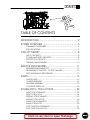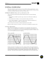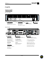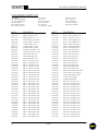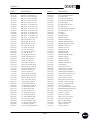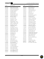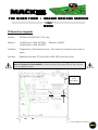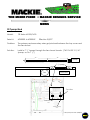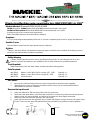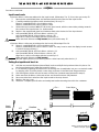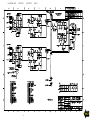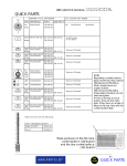
1
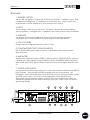
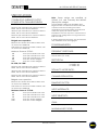
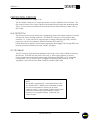
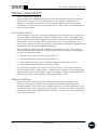
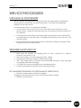
Go To Bulletins M•1400 / M•1400i / M•1200 SERVICE MANUAL 1998 MACKIE DESIGNS, INC. 820-179-00 Version 1.2 Page 3 is interactive CAUTION AVIS CAUTION AVIS RISK OF ELECTRIC SHOCK DO NOT OPEN RISQUE DE CHOC ELECTRIQUE NE PAS OUVRIR CAUTION: TO REDUCE THE RISK OF ELECTRIC SHOCK DO NOT REMOVE THE COVER NO USER SERVICEABLE PARTS INSIDE REFER SERVICING TO QUALIFIED PERSONNEL ATTENTION: POUR EVITER LES RISQUES DE CHOC ELECTRIQUE, NE PAS ENLEVER LE COUVERCLE. AUCUN ENTRETIEN DE PIECES INTERIEURES PAR L'USAGER. CONFIER L'ENTRETIEN AU PERSONNEL QUALIFIE. WARNING: TO REDUCE THE RISK OF FIRE OR ELECTRIC SHOCK, DO NOT EXPOSE THIS PRODUCT TO RAIN OR MOISTURE AVIS:POUR EVITER LES RISQUES D'INCENDIE OU D'ELECTROCUTION, N'EXPOSEZ PAS CET ARTICLE A LA PLUIE OU A L'HUMIDITE. TO PREVENT ELECTRIC SHOCK, DO NOT USE THIS POLARIZED PLUG WITH AN EXTENSION CORD, RECEPTACLE OR OTHER OUTLET UNLESS THE BLADES CAN BE FULLY INSERTED TO PREVENT BLADE EXPOSURE. POUR PREVENIR LES CHOCS ELECTRIQUES NE PAS UTILISER CETTE FICHE POLARISEE AVEC UN PROLONGATEUR, UN PRISE DE COURANT OU UNE AUTRE SORTIE DE COURANT, SAUF SI LES LAMES PEUVENT ETRE INSEREES A FOND SANS LAISSER AUCUNE PARTIE A DECOUVERT. The lightning flash with arrowhead symbol within an equilateral triangle is intended to alert the user to the presence of uninsulated "dangerous voltage" within the product's enclosure, that may be of sufficient magnitude to constitude a risk of electric shock to persons. Le symbole éclair avec point de fléche à l'interieur d'un triangle équilatéral est utilisé pour alerter l'utilisateur de la présence à l'interieur du coffret de "vlotage dangereux" non isole d'ampleur suffisante pour constituer un risque d'éléctrocution. The exclamation point within an equilateral triangle is intended to alert the user to the presence of important operating and maintenance (servicing) instructions in the literature accompanying the appliance. Le point d'exclamation à l'intérieur d'un triangle de la présence d'instructions importantes pour le fonctionnement et l'entretien (service) dans le livret d'instrucion accompagnant L'appareil. ® TABLE OF CONTENTS INTRODUCTION............................................................. 2 SYSTEM OVERVIEW ....................................................... 3 SUMMARY OF FEATURES .....................................................................4 SPECIFICATIONS...................................................................................6 CIRCUIT THEORY ........................................................... 8 INPUT CIRCUITRY..................................................................................8 POWER AMPLIFIER CIRCUITRY ...........................................................8 PROTECTION CIRCUITS .......................................................................9 THERMAL MANAGEMENT..................................................................10 SERVICE PROCEDURES............................................... 11 REQUIRED EQUIPMENT LIST ..............................................................11 TROUBLESHOOTING TIPS - OUTPUT FAILURES ................................12 TEST AND BIASING PROCEDURE......................................................13 PARTS............................................................................ 15 QUICK PARTS ......................................................................................15 CHASSIS ASSEMBLY............................................................................16 HEATSINK ASSEMBLY ..........................................................................18 COMPLETE PARTS LIST........................................................................20 SCHEMATICS / PCB LAYOUTS.................................... 23 INPUT PCB SCHEMATIC.....................................................................23 INPUT PCB LAYOUT ............................................................................24 DISPLAY PCB SCHEMATIC ................................................................25 DISPLAY PCB LAYOUT........................................................................26 MAIN PCB SCHEMATICS ...................................................................27 MAIN PCB LAYOUT ............................................................................30 SOFT START PCB SCHEMATIC ...........................................................31 SOFT START PCB LAYOUT...................................................................32 Click on any item to open that page M•1200/M•1400 SERVICE MANUAL INTRODUCTION This manual contains complete service information for the M•1200, M•1400 and M•1400i audio power amplifiers. Operating instructions will be touched on briefly. For complete operating instructions refer to the owner’s manual. The FR Series M•1200 and M•1400 are high power audio amplifiers designed for professional applications. They feature audiophile quality sound, excellent stability, extensive protection circuitry, and legendary Mackie reliability. Patented Fast Recovery circuitry allows the M•1200/M•1400 to recover from clipping without generating undesirable artifacts. SERVICE ON THE M•1200/M•1400 IS TO BE PERFORMED BY EXPERIENCED TECHNICIANS ONLY! To service the M•1200/M•1400, technicians should be familiar with op-amps, discrete analog circuitry, and troubleshooting high power solid state amplifiers. Presentation of this manual does not constitute endorsement of qualifications by Mackie Designs. ! SMD ! The M•1200/M•1400 makes extensive use of surface mount components. Servicing technicians should have the tools and experience to perform surface mount rework. TECHNICAL SUPPORT Mackie Designs Technical Support Department is available 8AM - 5PM PST, Monday Friday at 1-800-258-6883 (outside US call 011-425-487-4333) Please feel free to call with any questions (Better safe than sorry!). DISCLAIMER The information contained in this manual is proprietary to Mackie Designs, Inc. The entire manual is protected under copyright and may not be reproduced by any means without express written permission from Mackie Designs, Inc. 2 INTRODUCTION VERSION 1.1 SYSTEM OVERVIEW This section provides a quick summary of the M•1200/M•1400’s major features. It is not intended to take the place of the owner’s manual. It is included here to help servicing technicians familiarize themselves with the M•1200/M•1400. DIFFERENCES BETWEEN THE M•1400, M•1400i AND M•1200 The M•1200 and M•1400 are electronically identical products with the following exceptions: 1. The M•1400 has 12,000uF main filter caps, where the M•1200 and M•1400i have 10,000uF. 2. The M•1400 and M•1400i use a more powerful fan than the M•1200. 3. The M•1400 has Speakon connectors where the M•1200 and M•1400i have ¼” speaker outputs (both in addition to binding posts). The M•1200 was discontinued in 1998 and replaced by the M•1400i. Export M•1400’s also have a “Soft Start” circuit that is not installed on American units. FAST RECOVERY DESIGN Solid state power amplifiers have a reputation for sounding harsh when driven into clipping. The usual explanation is odd harmonics generated by hard clipping, but In fact much of the unpleasant sound is caused by latching and parasitic oscillations that occur as the amplifier recovers from clipping. TYPICAL AMPLIFIER MACKIE FR SERIES ARTIFACTS CAUSED BY LATCHING AND PARASITIC OSCILLATION Mackie’s Fast Recovery design recovers from clipping quickly without generating any undesirable artifacts. This performance is achieved by two unique design elements; the Full Symmetry Dual Differential front end provides excellent linearity while minimizing the need for negative feedback, and the Baker Clamp prevents output/driver device saturation. How these circuits operate is covered in depth in the circuit theory section. SYSTEM OVERVIEW 3 M•1200/M•1400 SERVICE MANUAL SUMMARY OF FEATURES FRONT PANEL 1. GAIN Detented gain controls adjust the level sent to each output section. The gain structure is designed so that a +4dBu (1.23V rms) input signal drives the amplifier to full rated power into 4Ω. 2. METERS The M•1200/M•1400’s meters indicate the relative output level of the amplifier referenced to full power. The SIG (signal present) senses the input prior to the gain control. 3. PROTECT The Protect LEDs light indicating the channel has been muted for one of the following reasons: • 4 second turn on delay • Output devices beyond Safe Operating Area (SOA), also lights SHORT LED(s). • Heatsink temperature beyond 80 degrees Celsius. 4. SHORT The Short LEDs light to show that the amplifier has engaged protection due to a short or low impedance on the output. 5. TEMP STATUS The HOT LED lights to indicate that the amplifier has engaged protection due to heatsink temperature or power transformer core temperature. 6. POWER SWITCH This remarkable device requires years of study to full comprehend. FULL SYMMETRY DUAL DIFFERENTIAL HIGH CURRENT DESIGN CH GAIN /dB 1 GAIN /dB 3v 18 20 22 2v 2 4 26 1 6 1 4 8 28 OL O L - 3 -3 - 6 -6 16 - 9 -9 14 - 2 0 - 2 0 1 8 3 v 2 0 8 3 01v 1v 1.23v (+4dBu) 1 4 SIG 2 SIG CH CH 2 1 CH 2 SENSITIVIT Y 1 ON INTERNALSTATUS 2 24 v PROTECT 2 6 30 SENSITIVITY 2 2 PROFESSIONALPOWER AMPLIFIER SHORT OFF TEMP STATUS 2 8 CH 1& 2 COL D 1.23v (+4dBu) 3 HOT POWER 4 5 SUMMARY OF FEATURES 6 VERSION 1.1 REAR PANEL 1. SPEAKER OUTPUTS The M•1400 has Speakon connectors where the M•1200 has ¼” speaker outputs. Both models have binding posts. For bridged mono operation, the + output comes from channel one’s positive terminal and - from channel two’s positive. 2. INPUT The M•1200/M•1400 has both XLR and ¼” TRS inputs. They are electrically identical (wired in parallel). In bridged mono or parallel mono mode channel 2 input is disabled. 3. THROUGH Yet another jack wired in parallel with the Inputs, the through jack provides a convenient way to chain amplifiers or pass the signal to any other device. 4. LOW CUT FILTER Sweeps the built in high pass filter from 10Hz to 170Hz. 5. CONSTANT DIRECTIVITY HORN EQ/AIR EQ Built in shelving EQ provides high frequency compensation when using constant directivity horns. 6. AMP MODE Three position slide switch selects STEREO, PARALLEL MONO or BRIDGE MONO operation. Channel One’s input signal is used for PARALLEL MONO and BRIDGE MONO operation. AMP MODE and OUTPUT APPLICATION switches should not be changed while the unit is on. 7. OUTPUT APPLICATION Placing the three position slide switch in its center position defeats the built in LIMITER for both channels. Selecting SUB WOOFER engages the built in low pass filter. The FREQUENCY switch selects between 125Hz and 63Hz cutoff for the low pass filter. In SUB WOOFER mode, inputs 1 and 2 are summed regardless of AMP MODE setting. (Remember, human hearing is unable to discern direction at frequencies where the wavelenth is greater than the distance between your ears, ~250Hz unless you have a grossly large head!) 4 CAUTION 2 1 CHANNEL / BRIDGE / MONO 2 STEREO TYPICAL MONO LOW CUT FILTER BALANCED O UNBAL ANCED R TYPIC 35Hz AL STAGE MONITOR 4 OHM LOAD MIN. 600 W A TTSCH 2OHMSLOADMIN. + MONO BRIDGE STAGE MONITOR OUTPUTAPPLICATION 100Hz - CH CH 1 OFF 2 + + - - 170Hz FULL RANGE CONSTANTDIRECTIV ITY 2k Hz 6k Hz AIR EQ 1 HORN EQ /AIR EQ 4.5k Hz 125Hz ON 63Hz OFF 2k Hz OFF TYPICAL SPEAKER OUTPUTS OFF TYPICAL THRU 5 SYSTEM OVERVIEW 3 170Hz CONSTANTDIRECTIV ITY FREQUENCY STEREO TYPICAL ON 100Hz OFF SUB WOOFER LIMITER (CH1 & CH2) HORNEQ/AIR EQ 4.5 kHz ON 120VAC 50/60 Hz 1500 WATTS 2 CHANNEL INPUT BRIDGE BALANCED O UNBALAN R CED TYPICAL 35 Hz 4 AMPMODE INPUT LOW CUT FILTER (MONO BRIDGE) 1200W A TTS 6 6k Hz AIR EQ THRU 7 3 5 5 M•1200/M•1400 SERVICE MANUAL SPECIFICATIONS Note: Power ratings are specified at 120VAC (U.S. and Canada) and 240VAC (Export) line voltages. CONTINUOUS AVERAGE OUTPUT POWER, BOTH CHANNELS DRIVEN: M•1200 225 watts per channel into 8 ohms from 20Hz to 20kHz, with no more than 0.025% THD 400 watts per channel into 4 ohms from 20Hz to 20kHz, with no more than 0.050% THD 600 watts per channel into 2 ohms from 20Hz to 20kHz, with no more than 0.095% THD Bridged mono operation: 800 watts into 8 ohms from 20Hz to 20kHz, with no more than 0.050% THD 1200 watts into 4 ohms from 20Hz to 20kHz, with no more than 0.095% THD The M•1200/M•1400 power amplifiers draw large amounts of current from the AC line with continuous sine wave testing. Accurate measurement of power requires a steady and stable AC supply. This means the line impedance must be very low to insure that the peak AC line voltage does not sag to less than 97% of its value. If driving highly reactive loads, we recommend that the limiter circuit be engaged. POWER BANDWIDTH: 20Hz to 70kHz (+0, –3 dB) Maximum Power at 1% THD: FREQUENCY RESPONSE: 250 425 640 850 1280 20Hz to 40kHz (+0, –1 dB) 10Hz to 70kHz (+0, –3 dB) watts per channel into 8 ohms watts per channel into 4 ohms watts per channel into 2 ohms watts into 8 ohms bridged watts into 4 ohms bridged M•1400 / M•1400i 250 watts per channel into 8 ohms from 20Hz to 20kHz, with no more than 0.012% THD 425 watts per channel into 4 ohms from 20Hz to 20kHz, with no more than 0.025% THD DISTORTION: THD, SMPTE IMD, TIM < 0.025% @ 8Ω < 0.050% @ 4Ω < 0.150% @ 2Ω SIGNAL-TO-NOISE RATIO: > 107 dB below rated power into 4 ohms 630 watts per channel into 2 ohms from 20Hz to 20kHz, with no more than 0.050% THD CHANNEL SEPARATION: Bridged mono operation: > 80 dB @ 1kHz 850 watts into 8 ohms from 20Hz to 20kHz, with no more than 0.025% THD DAMPING FACTOR: 1260 watts into 4 ohms from 20Hz to 20kHz, with no more than 0.050% THD 350 minimum Maximum Power at 1% THD: 300 500 700 1000 1400 watts per channel into 8 ohms watts per channel into 4 ohms watts per channel into 2 ohms watts into 8 ohms bridged watts into 4 ohms bridged INPUT IMPEDANCE: 20k balanced bridging INPUT SENSITIVITY: 1.23 volts (+4 dBu) for rated power into 4 ohms GAIN: 30.25 dB (32.5V/V) MAXIMUM INPUT LEVEL: 9.75 volts (+22 dBu) 6 SPECIFICATIONS VERSION 1.1 RISE TIME: LIMITER SECTION: < 4.4µs Complementary Positive and Negative Peak Detecting SLEW RATE: Voltage Slew Rate > 50V/µs > 100V/µs bridged Current Slew Rate > 32A/µs at 2Ω INDICATORS: 6 meter LEDs per channel SIG (Signal Present), –20, –9, –6, –3, OL (Overload) CMRR: CH 1 & 2 PROTECT LEDs SHORT LEDs > 40 dB, 20Hz to 20kHz TEMP STATUS COLD/HOT LEDs LOAD ANGLE: 8(±jx) time independent at 8Ω 4(±jx) time dependent, T > 6 min. at 4Ω 2(1±jx) time dependent, T > 2 min. at 2Ω POWER CONSUMPTION: HIGH FREQUENCY STABILITY: 65 watts at idle 900 watts with musical program fully loaded (2 ohms per side, or 4 ohms bridged) 550 watts with musical program fully loaded (4 ohms per side, or 8 ohms bridged) 850 watts at full power into 8 ohms (continuous sine wave) 1500 watts at full power into 4 ohms (continuous sine wave) 2500 watts at full power into 2 ohms (continuous sine wave) Unconditionally stable driving any reactive or capacitive load. AC LINE POWER: TRANSIENT RECOVERY: < 1µs for 20 dB overdrive @ 1kHz HIGH FREQUENCY OVERLOAD AND LATCHING: No latch up at any frequency or level. TURN ON DELAY: 3 seconds VARIABLE LOW-CUT FILTER: 10Hz (Off) to 170Hz, 2nd Order Bessel SUBWOOFER LOW-PASS FILTER: Switched: 63Hz/125Hz, 3rd Order Bessel CONSTANT DIRECTIVITY HIGH FREQUENCY BOOST: 2kHz to 6kHz (+3 dB points) 6 dB/octave high-frequency shelving filter, (shelving occurs at approximately 30kHz) US Europe Japan Korea 120VAC, 60Hz 240VAC, 50/60Hz 100VAC, 50/60Hz 220VAC, 60Hz AC DROP-OUT VOLTAGE: At approximately 50% of rated line voltage PHYSICAL: Height Width Depth Overall Depth Handle Depth Weight 3.5 inches 19.0 inches 15.25 inches 16.25 inches 1.25 inches 36 pounds (89mm) (483mm) (387mm) (413mm) (32mm) (16.3kg) Since we are always striving to make our stuff better at Mackie Designs by incorporating new and improved materials, components, and manufacturing methods, we reserve the right to change these specifications at any time without notice. SPECIFICATIONS 7 M•1200/M•1400 SERVICE MANUAL CIRCUIT THEORY Much of the circuitry in the M•1200/M•1400 is self explanatory from the schematic. This section will explain the unique circuits and architecture. Samples in this section will refer to Channel 1 (Left) for circuitry that is identical on both channels. INPUT CIRCUITRY Refer to schematic on page 23. The signal path begins with the INPUT BOARD. Following Channel 1’s input, signal is fed to a unity gain differential op-amp, U1A. The signal is next sent to U1B which serves as both HPF and CD horn EQ. If not in SUBWOOFER mode, the summing amp (U2B) and LPF’s (U3A, U3B) are bypassed. The signal is sent via J11 to the gain control on the DISPLAY BOARD. After the gain control, the signal is buffered by U7A, returned to the INPUT BOARD and routed to the MAIN BOARD via J16. Channel 2’s input signal path is electrically identical to Channel 1’s in STEREO mode. In PARALLEL MONO mode Channel 2’s input signal is ignored and Channel 1’s input is sent to Channel 2’s gain control via SW5A. For BRIDGE MONO operation, Channel 1’s input signal is inverted by U2A and routed to the MAIN BOARD via SW5C. POWER AMPLIFIER CIRCUITRY Refer to schematic on page 27. The M•1200/M•1400 use a class AB triple darlington output with complementary output devices. The main power supply is +/- 80V, there is also a +/- 90V supply for the front end circuitry. Channels are muted for 4 seconds on power up as C53 charges via R203. Muting is achieved by turning off Q73, removing current sources for the differential pairs. (Wait a minute! PAIRS? Read on…) An immediately obvious departure from standard designs is the Dual Differentials and Symmetrical Voltage Amps. The reasoning behind this front end architecture is actually quite simple. Transistors transfer characteristics are not entirely linear, so even the best conventional front end design will introduce some distortion. Most amplifiers use negative feedback to reduce this problem (creating a few more in the process). Mackie FR Series amplifiers take a different approach. By using two complementary “mirror image” front end circuits any distortion caused by non-linear transistor curves is effectively canceled out in the bias string, without feedback! Another design feature unique to Mackie FR Series Amplifiers is the Baker Clamp. The Baker Clamp has two functions; 1) Prevent output/driver transistors saturating, 2) Drive the LIMITER LDR. Referring to the left main amp schematic, Q27 is a common base amplifier, it will turn on if Q31’s collector rises more than two diode drops above the +80V supply, preventing it from rising further. There are three diode drops between Q31’s collector and the base of driver transistor Q28 (D3, D2, Q29Vbe). Q29 will never see a voltage greater than one diode drop below the +80V supply, even if the +80V supply fluctuates. Q27 also drives the limiter LDR LED U2A. The negative side has the same circuit mirrored. 8 CIRCUIT THEORY VERSION 1.1 PROTECTION CIRCUITS Refer to schematics on pages 27-29. The M•1200/M•1400 has two output protection circuits in addition to the rail fuses. The first mutes the amp if the output devices are loaded beyond their safe operating area (SOA). The second is a crowbar circuit that ensures the rail fuses blow if there is DC on the output. SOA PROTECTION The SOA protection circuit senses the voltage drop across the emitter resistors much like standard VI current limiting transistors. Q76 and Q77 will turn on if the emitter drop exceeds ~1V. If they are on for long enough to charge C38 (through R159), the SOA protection circuit is activated by transistor switches Q79 and Q78. If SOA detection is tripped, the channel is muted by discharging C53 through R200 and D65, fan speed is increased, and the “SHORT” LED lights. DC CROWBARS The DC Crowbar circuit protects speakers in the event of an output failure by blowing all rail fuses. SCRs Q21-24 are used to short the +/- 80V supply supplies to ground. Output signal from both sides is fed through 100K resistors R90, R89 to C21, essentially forming a LPF. DC on either output will trigger comparator U4A (positive) or U4B (negative). The SCRs are then fired via driver transistors Q87, Q88. NOTE: The LM339 comparator IC is used extensively in the M•1200/M•1400. It differs from a standard op-amp used as a comparator in that it has an open collector output. If the voltage at the inverting input exceeds the non-inverting, the LM339’s output switches to it’s negative supply. Otherwise, the output is open. CIRCUIT THEORY 9 M•1200/M•1400 SERVICE MANUAL THERMAL MANAGEMENT Refer to schematic on page 29. The M•1200/M•1400 T-Design Heatsink/Fan cools output devices evenly and does not collect dust on the circuitry. The fan operates at two speeds, controlled by the amplifier. An LM35DZ mounted in the center of the heatsink provides temperature information to the fan control and overtemp circuits. There is also a thermal breaker in the power transformer. FAN CONTROL CIRCUIT The fan voltage comes from a feedback regulator circuit formed by Q91 and Q92. The output voltage is programmed by the ratio of R209 to R211// R207 (//=parallel). When the unit is powered up C83 charges through R241 providing a 40 second delay before the fan starts. As C83 charges, U6D’s output switches to -16V, starting the fan. Then U6A’s output switches to open, allowing U6B to increase the fan speed, if triggered. R240 and C82 give the fan extra voltage when starting. The fan speed is increased by U6B adding R211 in parallel with R207. (Q91 wants it’s base a diode drop above ground, so Q92 doubles its Emitter voltage). U6B is triggered by U4D to increase fan speed if; • Channel 1 SOA protection is activated (U5C), OR • Channel 2 SOA protection is activated (U5D), OR • The heatsink is above 60 deg C (U5B) AND program is detected (U4C), OR • The heatsink temperature is above 80 deg C (U5A). U6C and Q89 are used to reset the circuit on power down. Under normal operation C50 is charged via D57, Holding Q89 off. When power is removed C50 discharges and Q89 switches on as the rails collapse. When the voltage on Q89’s collector falls below ground U6 switches to the negative rail discharging C82 and C83. THERMAL SHUTDOWN Extreme heatsink or transformer core temperature will activate OVERTEMP. U5A activates overtemp if the LM35DZ detects heatsink temperature above 80 deg C. Feedback resistor R137 rescales U5A’s voltage reference so that the heatsink must cool to below 50 deg C before overtemp is deactivated. Overtemp can also be activated by the power transformer thermal breaker (via Q89). In either case, both channel are muted via D69 and D66. 10 CIRCUIT THEORY VERSION 1.1 SERVICE PROCEDURES MECHANICAL PROCEDURES The M•1200/M•1400 design allows easy removal of all components and assemblies. Disassembly and reassembly should be self evident. This manual has exploded diagrams in the parts section. Several important points concerning the assembly: • 4 of the screws that secure the top cover also hold the front extrusion (curved piece) in place. When removing the top cover, be careful that the front extrusion is not dropped. • If the MAIN PCB is removed, be sure the smaller head machine screws (750-050-04) are replaced next to the filter caps. The larger head machine screws can arc to the capacitor body. • Be sure all tywraps are replaced and that no wires are in danger of being pinched in-between the cover and heatsink. REQUIRED EQUIPMENT LIST • • • • • • • 30 MHz dual trace oscilloscope DMM (Must be capable of measuring 8mV DC with a minimum of 2 digits of accuracy, and down to .1Ω) Sine wave oscillator / Function generator (20Hz - 20KHz) 4 load resistors (8Ω with a minimum 500W power rating) 10A / 120V Variac With AC voltmeter and a defeatable ammeter (1 Amp full range) or wattmeter (300 Watts full range) 0.1uF 400V film capacitor installed across dual banana plug 16 AWG shorting jumper installed across dual banana plug RECOMMENDED EQUIPMENT LIST (PERFORMANCE VERIFICATION) • Distortion analyzer and low distortion oscillator. (Capable of resolving distortion as low as 0.002% from 20Hz to 20KHz) • 2500W AC power source. SERVICE PROCEDURES 11 M•1200/M•1400 SERVICE MANUAL TROUBLESHOOTING TIPS - OUTPUT FAILURES After a catastrophic failure, it is likely that the four +/-80V supply fuses will be blown. Replace fuses and very slowly bring up the Variac while monitoring line consumption. It is likely that substantial line current will be pulled due to shorted output parts. At the same time, look for DC offset at the output. Offset of greater than +/- 2.8V will trigger the protection circuits and re-blow the four fuses. Keep the output offset below +/- 2V, or temporarily defeat the DC-offset detector (Lift one side of D56). Remove the main board from the unit and check for shorted output transistors. If one bad output is found, replace all eight in the channel. When an output device shorts it can place high current stresses on the other output parts. These output parts can fail over time. Since long term reliability is paramount, please replace all the outputs. All eight of the 3W 0.22Ω emitter resistors must be verified for proper value. Any offtolerance, or open parts, need to be replaced. An off tolerance (higher resistance) emitter resistor will prevent it’s related output transistor from “doing it’s share” and will place more stress on it’s mates in the output section. Also verify the 8 base drive resistors (2.2Ω, 1/4W, fusible) are all OK. Verify that the drivers and pre-drivers are not shorted. If one driver is shorted replace it’s mate. Do the same with the pre-drivers. Also check all the resistors surrounding the drivers and pre-drivers. Check the VI limiters and detectors. It is not uncommon to damage these parts when the amplifier fails in a spectacular way! Look for shorts on Q76, Q77, Q94, Q95, Q83, Q84, Q96, and Q97. Verify proper value on the resistors that go to the bases of these devices. It is critical that these sections are working correctly. Shorted transistors can cause some odd asymmetrical clipping problems. Open parts will not allow the current limiting to operate effectively. If problems exist in these sections the amplifier might fail into a short, or might clip prematurely when loaded to 2Ω. All of the above trouble shooting (Not including part replacement) takes perhaps 15 to 30 minutes to do. If you take the time, and do all that is indicated above, it will allow 99% of the amplifiers to come up the first time! Trying to hurry, and skipping what is suggested, can lead to a frustrating and time consuming repair. Slowly bring up the supply and verify that line consumption isn’t excessive and that the output is centered (no DC offset). It might be desirable to defeat the amplifier muting (Connect U5-12, 13, & 14 together) temporarily so the amplifiers are active even when the supplies are still very low. If the amp stays centered, verify that it will pass a nice clean sine wave. Remove any test jumpers (I.E. DC-fault defeat & muting defeat) and proceed to the “Reliability Verification” section. 12 SERVICE PROCEDURES VERSION 1.1 BIAS AND TEST PROCEDURE After the unit has been repaired, the following should be done to assure long term reliable operation. If a distortion analyzer is present, distortion specifications should be verified. 1. Adjusts bias in both channels (R1 & R51) for 8mV +/- 0.3mV at bias test points (J53 & J54) after unit has idled for a few minutes. With Full AC line voltage applied to unit, it will pull around 65W from the line (900mA at 120V). Measure for DC offset on both output connectors. DC offset should be less than +/- 50mV. 2. Apply a 1KHz sine wave to the inputs and verify that the unloaded outputs have a waveform that is symmetrical and undistorted. Drive the outputs into clipping and verify symmetrical “flat-topping” on the waveform. 3. Reduce output levels, install the 0.1uF capacitor jumper from the output to ground connections, and verify that clipping behavior is proper. Verify that no high frequency oscillation occurs near and at clipping (parasitic oscillation). 4. Remove capacitive loading and minimize sine output. Verify and re-adjust bias if required. Note that the bias will not drift appreciably in a unit that is functioning properly. 5. Connect the amplifier directly to the AC line and connect an 8Ω dummy load to both channels. Bring sine wave level up on both channels and verify symmetrical clipping. The output will clip somewhere between 120V - 140V pk/pk depending on how stiff the line is. Clipping should be as described above. Add the 0.1uF capacitive loading and verify clipping is still well behaved. 6. Individually load Channel 1 and Channel 2 with 2Ω. Clipping should be symmetrical, well behaved , and occur somewhere around 80V - 100V pk/pk. Verify that clipping is well behaved after adding the 0.1uF capacitive loading. 7. Reduce output level to 20V pk/pk and short first channel one and then channel two. The front panel “short” and “protect” LEDs should flash on the respective channels. 8. Place amplifier in bridge mode and connect 4Ω loading to bridge outputs (across both “+” output binding posts). Slip some card stock between the heatsink-outlets and chassis sides. Monitor one of the outputs and adjust for a 20V pk/pk signal. Short across both outputs and verify that all four ‘Short” and “Protect” LEDs light and the amplifier mutes. 9. Remove short, monitor one of the outputs, and adjust for a 60V pk/pk sine output (450W of output power bridged). After a few minutes the fan will begin running fast (heatsink at 60°C) and a short time later the amplifier will mute (heatsink at 80°C). The “Hot” and “protect” LEDs will come on. Remove card stock and after a few minutes the amplifier will come out of mute mode and the “cold” LED will return. 10. Disconnect loading and remove drive. Reconnect amplifier to Variac and confirm that the idle consumption is roughly 65W or 900mA, as before. Connect the amplifier to speakers and verify that it sounds OK with music. SERVICE PROCEDURES 13 M•1200/M•1400 SERVICE MANUAL (THIS PAGE UNINTENTIONALLY LEFT BLANK), THOSE RESPONSIBLE HAVE BEEN PUT TO THE SWORD 14 SERVICE PROCEDURES VERSION 1.1 PARTS QUICK PARTS FRONT PANEL FULL SYMMETRY DUAL DIFFERENTIAL HIGH CURRENT DESIGN CH GAIN /dB 1 20 22 2v 2 4 26 8 28 OL O L - 3 -3 - 6 -6 16 - 9 -9 14 - 2 0 1 8 - 2 0 3 v 2 2 2 0 8 3 01v 1v 1.23v (+4dBu) SIG SIG 2 2 24 v CH CH 1 2 SENSITIVIT Y ON INTERNALSTATUS PROTECT 2 6 30 SENSITIVITY CH GAIN /dB 3v 18 1 6 1 4 PROFESSIONALPOWER AMPLIFIER SHORT TEMP STATUS 2 8 OFF CH 1& 2 COL D 1.23v (+4dBu) HANDLE ASSEMBLYS RIGHT, 080-023-10 LEFT, 080-023-20 SCREW(TO CHASSIS),700-028-04 HOT POWER GAIN CONTROLS 5KL POT, 130-036-00 KNOB, 760-061-00 NUT, 705-013-00 STAR WASHER, 710-023-00 POWER SWITCH 500-022-00 ALL LEDS RED T-1, 304-001-00 GREEN T-1, 304-004-00 REAR PANEL CAUTION 1 CHANNEL / BRIDGE / MONO STEREO TYPICAL MONO INPUT BRIDGE BALANCED O UNBALAN R CED TYPICAL 35 Hz (MONO BRIDGE) 1200W A TTS LOW CUT FILTER BALANCED O UNBAL ANCED R TYPIC 35Hz AL STAGE MONITOR 4 OHM LOAD MIN. 600 W A TTSCH 2OHMSLOADMIN. + MONO BRIDGE STAGE MONITOR OUTPUTAPPLICATION 100Hz - CH CH 1 2 + + - - OFF 170Hz LIMITER (CH1 & CH2) HORNEQ/AIR EQ 4.5 kHz STEREO TYPICAL ON 2k Hz 6k Hz AIR EQ SPEAKER OUTPUTS ON SPEAKER OUTPUTS BINDING POSTS, 400-119-00 BINDING POST SCREW, 700-011-00 STRAIN RELIEF 740-004-00 M•1400 SPEAKON, 400-138-00 SCREW, 700-055-00 M•1200/M•1400i ¼” JACK, 400-118-00 WASHER, 710-019-00 SLOTTED NUT, 705-015-00 INTERNAL FUSES RAIL FUSES; 10A 5X20MM, 510-021-00 MAIN FUSE; 20A, 510-017-00 8A, 510-023-00 HORN EQ /AIR EQ 4.5k Hz 125Hz OFF 170Hz CONSTANTDIRECTIV ITY FREQUENCY ON 2k Hz 63Hz OFF TYPICAL OFF TYPICAL THRU AC LINE CORD US, 640-006-00 EUROPE, 640-007-01 JAPAN, 640-007-02 ENGLAND, 640-007-03 ITALY, 640-007-04 AUSTRALIA, 640-007-05 SWITZERLAND, 640-007-06 100Hz OFF SUB WOOFER FULL RANGE CONSTANTDIRECTIV ITY 120VAC 50/60 Hz 1500 WATTS 2 CHANNEL AMPMODE INPUT LOW CUT FILTER 6k Hz AIR EQ THRU INPUT SECTION ALL KNOBS, 760-048-04 LOW CUT, 50KZx2 POT, 130-017-02 CD HORN EQ, 10KC POT, 130-037-02 ¼” INPUT JACK, 400-214-00 ¼” JACK WASHER, 710-002-00 ¼” JACK NUT, 705-003-00 MALE XLR JACK, 400-142-00 FEMALE XLR JACK, 400-141-00 XLR JACK SCREWS,700-055-00 DP3T SWITCHES, 500-023-00 DPDT SWITCHES, 500-024-00 PARTS 15 M•1200/M•1400 SERVICE MANUAL CHASSIS ASSEMBLY 1 2 3 16 17 4 1 7 5 6 15 14 13 10 8 9 1 11 16 12 PARTS 18 VERSION 1.1 CHASSIS ASSEMBLY PARTS LIST ITEM # PART # DESCRIPTION NOTES 1 700-028-02 SEMS 6-32X3/8 PHP BLKZC ALL SIDE PANEL SCREWS 2 550-221-00 TOP COVER - M1200 3 700-041-04 MCH 6-32X3/8 FL 100DG BLK 4 551-029-00 EXTR SCRN DSPLY BZL-M1200 4 551-029-10 EXTR SCRN DSPLY BZL-M1400 5 700-041-04 MCH 6-32X3/8 FL 100DG BLK 6 550-277-00 SCREEN MANIFOLD - M1400 7 550-223-20 SIDE RAIL LEFT - M1200 8 550-223-10 SIDE RAIL RIGHT - M1200 9 550-222-00 BTM COVER - M1200 9 550-244-00 BOTTOM COVER - M1400 10 080-023-20 PNT HANDLE ASSY LEFT 11 080-023-10 PNT HANDLE ASSY RIGHT 700-028-04 SEMS 6-32X3/4 PHP BLKZC HANDLE ASSY TO CHASSIS 700-041-04 MCH 6-32X3/8 FL 100DG BLK HEATSINK TO CHASSIS BOTTTOM 12 TOP COVER TO CHASSIS MANIFOLD TO FAN TRANSFORMER / MOUNTING 600-016-00 XFMR M1200 120V 600-016-01 XFMR M1200 230V 600-016-02 XFMR M1200 100V 705-019-00 NUT HEX 5/16-18 710-017-00 WASH SPLTLCK 5/16 HEAVY 710-024-00 WASH FLAT 5/16 HARD (USS) 550-249-00 PLATE XFMR MTG - M1200 780-111-00 RUBBER PAD 700-059-00 HEX 5/16-18X3IN GD-5 13 550-247-00 SHIELD INPUT - M1200 14 780-042-00 INSUL MYLAR INPUT SHIELD 15 055-079-00 PCB ASSY INPUT 1200/1400 16 700-028-02 SEMS 6-32X3/8 PHP BLKZC 17 760-048-04 KNOB 9MM DARK GRAY 18 550-275-00 SPACER PLATE - AMPLIFIER 710-002-00 WASHER FOR ¼” JACKS 705-003-00 NUT FOR ¼” JACKS 700-055-00 MCH 4-24X3/8 PHP BLK HILO 055-080-00 PCB ASSY DISPLY 1200/1400 055-081-00 PCB ASSY MAIN - 1200 080-072-01 PCB ASSY MAIN - M1400 080-072-02 PCB ASSY MAIN - M1400i 700-028-02 SEMS 6-32X3/8 PHP BLKZC MAIN PCB TO CHASSIS EXCEPT FOR: 700-050-04 MCH 6-32X3/8 FIL PHL CLR ! USE THESE NEXT TO CAPS ! 700-011-00 MCH 4-40X1/4 BTNSKT BLKOX OUPTUT TERMINALS TO CHASSIS 710-019-00 WASH FIBRE BLK (W/JACK) 705-015-00 NUT SLOT NCKL 700-055-00 MCH 4-24X3/8 PHP BLK HILO PARTS INPUT PCB TO SHIELD XLR JACK SCREWS 17 M•1200/M•1400 SERVICE MANUAL HEATSINK ASSEMBLY 18 PARTS VERSION 1.1 HEATSINK ASSEMBLY PARTS LIST ITEM # PART # DESCRIPTION 1 551-032-00 EXTR FAB HEATSINK - M1200 2 410-003-00 INSL SILPAD K6 W/ADHESIVE 3 055-081-00 PCB ASSY MAIN - 1200 3 080-072-01 PCB ASSY MAIN - M1400 3 080-072-02 PCB ASSY MAIN - M1400i 4 550-255-00 PIGGYBACK CLIP 5 700-058-02 MCH 4-40X1/2 SKT CLRZC 6 710-020-00 WASH NO.4 COMPRESSION 7 710-022-00 WASH FLAT NO.4 FENDER 8 550-224-00 BRACKET SUBSINK - M1200 9 410-003-00 INSL SILPAD K6 W/ADHESIVE 11 700-010-00 TF 6-32X1/4 PHP BLKZC 12 710-013-00 WASH FLAT NO.6 FIBRE 13 700-010-04 TF 6-32X3/8 PHP BLKZC 14 550-237-00 SPRING CLIP SUBSINK-M1200 15 700-028-02 SEMS 6-32X3/8 PHP BLKZC 16 550-225-00 HEATSINK COWLING - M1200 17 700-010-00 TF 6-32X1/4 PHP BLKZC 18 770-006-00 FAN 80MM 24VDC-MECHATRONI 18 770-007-00 FAN 80MM 24VDC-PANASONIC 19 550-219-00 BRKT FAN PS - SR40.8 20 700-047-04 MCH 10-32X3/8 FIL PHL CLR 21 700-028-02 SEMS 6-32X3/8 PHP BLKZC 22 400-083-00 2P .100X1 22GA END 24 700-058-02 MCH 4-40X1/2 SKT CLRZC 25 710-020-00 WASH NO.4 COMPRESSION PARTS 19 M•1200/M•1400 SERVICE MANUAL COMPLETE PARTS LIST 040- Cables 055- Finished PCB Assys 100- Pots and Resistors 200- Capacitors 300- Semiconductors 400- Jacks/Connectors 500- Switches 510- Fuses 550- Chassis Metal 600- Transformers 601- Inductors 610- Wires and Cables 640- AC Line Cords 700- Hardware 760- Knobs/Plastic 790- Misc./Packing 800- Printed Material PART # DESCRIPTION PART # DESCRIPTION 040-033-02 RIB 28GA TRANS 20C 18IN 100-094-00 RES CF .125W 5% 75K OHM 040-033-03 RIB 28GA TRANS 20C 4IN 100-097-00 RES CF .125W 5% 100K OHM 040-117-02 RIB 28G TRNS 10C .10 11.5 100-109-00 RES CF .125W 5% 1M OHM 055-079-00 PCB ASSY INPUT 1200/1400 100-110-00 RES CF .125W 5% 360K OHM 055-080-00 PCB ASSY DISPLY 1200/1400 100-111-00 RES CF .125W 5% 390K OHM 055-081-00 PCB ASSY MAIN - 1200 105-277-00 RES MF .125W 1% 750 OHM 080-072-01 PCB ASSY MAIN - M1400 105-331-00 RES MF .125W 1% 2K49 OHM 080-072-02 PCB ASSY MAIN - M1400i 110-036-00 RES CF .25W 5% 300 OHM 080-034-00 PCB ASSY SOFT START – 120V 110-046-00 RES CF .25W 5% 750 OHM 080-034-01 PCB ASSY SOFT START – 240V 115-427-00 RES MF .25W 1% 24K9 OHM 080-023-10 PNT HANDLE ASSY RIGHT 121-097-00 RES MO 1W 5% 10K OHM 080-023-20 PNT HANDLE ASSY LEFT 123-009-00 RES MO 3W 5% .22 OHM 080-035-00 PWR SW HARNESS - AMP 123-033-00 RES MO 3W 5% 2.2 OHM 100-001-00 RES CF .125W 5% 10 OHM 123-056-00 RES MO 3W 5% 20 OHM 100-017-00 RES CF .125W 5% 47 OHM 123-071-00 RES MO 3W 5% 82 OHM 100-023-00 RES CF .125W 5% 82 OHM 123-085-00 RES MO 3W 5% 330 OHM 100-027-00 RES CF .125W 5% 120 OHM 123-109-00 RES MO 3W 5% 3.3K OHM 100-030-00 RES CF .125W 5% 160 OHM 123-124-00 RES MO 3W 5% 13K OHM 100-031-00 RES CF .125W 5% 180 OHM 125-020-00 RES WW 15W 5% 82 OHM CMNT 100-035-00 RES CF .125W 5% 300 OHM 130-017-02 POT RTY 50KC 12MM DUAL TN 100-040-00 RES CF .125W 5% 430 OHM 130-036-00 POT RTY 5KA 16MM DL DTNT 100-042-00 RES CF .125W 5% 510 OHM 130-037-02 POT RTY 10KC 9MM TN 100-045-00 RES CF .125W 5% 680 OHM 130-038-00 POT TRIM 500B HORIZ 100-049-00 RES CF .125W 5% 1K OHM 140-025-00 RES TF SM .1W 5% 10 OHM 100-050-00 RES CF .125W 5% 1K1 OHM 140-057-00 RES TF SM .1W 5% 220 OHM 100-056-00 RES CF .125W 5% 2K OHM 140-060-00 RES TF SM .1W 5% 300 OHM 100-061-00 RES CF .125W 5% 3K3 OHM 140-065-00 RES TF SM .1W 5% 470 OHM 100-068-00 RES CF .125W 5% 6K2 OHM 140-068-00 RES TF SM .1W 5% 620 OHM 100-071-00 RES CF .125W 5% 8K2 OHM 140-073-00 RES TF SM .1W 5% 1K0 OHM 100-072-00 RES CF .125W 5% 9K1 OHM 140-076-00 RES TF SM .1W 5% 1K3 OHM 100-073-00 RES CF .125W 5% 10K OHM 140-078-00 RES TF SM .1W 5% 1K6 OHM 100-075-00 RES CF .125W 5% 12K OHM 140-080-00 RES TF SM .1W 5% 2K0 OHM 100-076-00 RES CF .125W 5% 13K OHM 140-081-00 RES TF SM .1W 5% 2K2 OHM 100-080-00 RES CF .125W 5% 20K OHM 140-083-00 RES TF SM .1W 5% 2K7 OHM 100-082-00 RES CF .125W 5% 24K OHM 140-087-00 RES TF SM .1W 5% 3K9 OHM 100-083-00 RES CF .125W 5% 27K OHM 140-089-00 RES TF SM .1W 5% 4K7 OHM 100-084-00 RES CF .125W 5% 30K OHM 140-092-00 RES TF SM .1W 5% 6K2 OHM 100-086-00 RES CF .125W 5% 36K OHM 140-094-00 RES TF SM .1W 5% 7K5 OHM 100-089-00 RES CF .125W 5% 47K OHM 140-097-00 RES TF SM .1W 5% 10K OHM 100-092-00 RES CF .125W 5% 62K OHM 140-106-00 RES TF SM .1W 5% 24K OHM 100-093-00 RES CF .125W 5% 68K OHM 140-108-00 RES TF SM .1W 5% 27K OHM 20 PARTS VERSION 1.1 PART # DESCRIPTION PART # DESCRIPTION 140-111-00 RES TF SM .1W 5% 36K OHM 300-003-00 DIO SW DL4148 100V SM 140-115-00 RES TF SM .1W 5% 51K OHM 300-007-00 DIO SW 1SS244-SUB 1SS245 140-123-00 RES TF SM .1W 5% 100K OHM 301-006-00 THY 2N6507 400V 140-124-00 RES TF SM .1W 5% 120K OHM 301-007-00 DIO PWR DUAL FEP30 (D7) 140-139-00 RES TF SM .1W 5% 470K OHM 301-008-00 DIO PWR DUAL FEN30 (D8) 140-147-00 RES TF SM .1W 5% 1M OHM 301-009-00 DIO PWR 1N4004 145-318-00 RES MF SM .1W 1% 2K00 OHM 301-010-00 DIO PWR 1N5404 3A 400V 145-389-00 RES MF SM .1W 1% 10K0 OHM 301-014-00 DIO PWR 1N4007 145-397-00 RES MF SM .1W 1% 12K1 OHM 302-001-00 DIO ZEN 1N5261B 47V 500MW 145-406-00 RES MF SM .1W 1% 15K0 OHM 302-003-00 DIO ZEN 1N4745A 16V 1W 145-469-00 RES MF SM .1W 1% 68K1 OHM 304-001-00 LED RED T-1 145-478-00 RES MF SM .1W 1% 84K5 OHM 304-004-00 LED GREEN T-1 145-485-00 RES MF SM .1W 1% 100K OHM 310-002-00 XSTR PNP 2N4403 145-547-00 RES MF SM .1W 1% 442K OHM 310-007-00 XSTR NPN 2N4401 150-009-00 RES FUS .25W 5% 2.2 OHM 310-023-02 XSTR NPN 2SC2362K TR 150-037-00 RES FUS .25W 5% 33 OHM 310-028-00 XSTR PNP 2SB940A POWER 150-045-00 RES FUS .25W 5% 68 OHM 310-029-00 XSTR NPN 2SD1264A POWER 200-001-02 PLY .012UF 10% 100V TR 310-032-02 XSTR PNP 2SA1016K TR 200-004-02 PLY .047UF 10% 100V TR 310-033-00 XSTR PNP MJL21193 200-007-02 PLY .01UF 10% 100V TR 310-034-00 XSTR NPN MJL21194 200-015-02 PLY .0047UF 10% 100V PEI 310-035-00 XSTR PNP 2SA1478 200-022-02 PLY .47UF 5% 50V TR 310-036-00 XSTR NPN 2SC3788 200-023-00 PLY/BX .001UF 20% 250V Y2 310-037-00 XSTR NPN MJE340 POWER 200-024-00 PLY/BX .01UF 20% 250V Y2 310-038-00 XSTR PNP MJE350 200-025-02 PLY/BX .56UF 5% 63V TR 310-042-00 XSTR NPN MJE15032 200-036-00 PLY/BX .1UF 10% 250V 310-043-00 XSTR PNP MJE15033 205-002-02 MICA 270PF 5% 500V TR 311-002-00 XSTR PNP MMST4403 SM 210-001-02 CER .01UF +80/-20% 50V TR 320-004-00 OPAMP 4560F 210-010-02 CER 47PF 5% 500V NPO TR 323-001-00 LM339 QUAD COMP 210-017-02 CER 470PF 5% 500V Y5E TR 323-002-00 LM339D QUAD COMP SM 211-003-00 CER .001UF 10% 50V AX 329-012-00 VTL5C10 OPTOCOUPLER 211-009-00 CER .1UF 20% 50V AX 329-014-00 LM35DZ PREC TEMP SENSOR 212-001-00 CER .01UF 10% 50V X7R SM 400-059-00 TERM QDISC .250 MALE PCMT 212-004-00 CER 220PF 5% 50V NPO SM 400-060-00 FUSE CLIP PCMT 5MM DIA 212-009-00 CER 47PF 5% 50V NPO SM 400-061-00 HDR 2P .100X1 STR LOCK 212-010-00 CER .1 +80/-20 25V Z5U SM 400-065-00 TERM QDISC .250 F 18-22GA 220-001-02 LYT 22UF 20% 25V RAD TR 400-077-00 HDR 20P .1X2 STR LCK SHRD 220-002-02 LYT 47UF 20% 25V RAD TR 400-078-00 HDR 10P .1X2 STR LCK SHRD 220-004-02 LYT 470UF 20% 6.3V RAD TR 400-083-00 2P .100X1 22GA END 220-007-00 LYT 100UF 20% 100V RAD 400-118-00 JACK 1/4 HORIZ PCMNT MONO 220-011-02 LYT 100UF 20% 25V RAD 400-119-00 TERM BANANA QUAD HRZ PCMT 220-014-00 LYT 2.2UF 20% 50V RAD 400-129-00 FUSE CLIP .25 DIA PC MNT 220-025-00 LYT 1000UF 20% 35V RAD 400-133-00 HDR 6CK 11A/600V 220-027-02 LYT 10UF 20% 50V RAD TR 400-134-00 RECP 6CK 11A/600V 220-033-00 LYT 10000UF 20% 80V RAD 400-135-00 TERM 11A/600V F 18-20GA 220-034-00 LYT .47UF 20% 100V RAD 400-138-00 SPEAKONS HORIZ 4 CKT 220-035-00 LYT 12000UF 20% 80V RAD 400-141-00 XLR 3P F VERT A-SERIES 220-039-00 LYT 1000 20 25V RAD SMDIA 400-142-00 XLR 3P M VERT A-SERIES 220-040-00 LYT 10UF 20% 160V RAD 400-143-00 HDR 3P .100X1 STR 300-001-00 DIO SIG 1N4148 100V 500MW 400-171-00 HDR 2P .100X1 STR PARTS 21 M•1200/M•1400 SERVICE MANUAL PART # DESCRIPTION PART # DESCRIPTION 400-172-00 TERM SOLDER-IN 18AWG 700-058-02 MCH 4-40X1/2 SKT CLRZC 400-173-00 TERM .25 QKDS PCMT STABLE 700-059-00 HEX 5/16-18X3IN GD-5 400-210-00 TERM QDISC .250 F 18-22GA 704-001-01 PEMNUT 6-32 .038 STL 400-214-00 JACK 1/4 V PCMNT 1MM WASH 704-001-02 PEMNUT 6-32 .054 STL 410-003-00 INSL SILPAD K6 W/ADHESIVE 704-007-01 PEMNUT 4-40X.060L SS FLSH 500-022-00 SW RCKR ILLUMINATED 704-023-03 STUD 6-32X.500 STL FLSH 500-023-00 SW SLIDE 4P3T MINI 705-001-00 KEPNUT 6-32 500-024-00 SW SLIDE DPDT MINI 705-003-00 NUT (SPLD W/JACK) 501-002-00 RELAY SPDT 30AMP 110VDC 705-013-00 NUT HEX M7 BLK 510-017-00 FUSE SB 20A 3AB 1/4X1-1/4 705-015-00 NUT SLOT NCKL SPLD W/JACK 510-021-00 FUSE FB 10A 5X20MM 250V 705-018-00 NUT HEX 5/16-18 (GD-5) 550-219-00 BRKT FAN PS - SR40.8 706-036-01 6-32X.188L STL PEM 550-221-00 TOP COVER - M1200 706-036-03 STDF 6-32X.312L STL PEM 550-222-00 BTM COVER - M1200 706-045-00 SPCR PVC .770 LED HI TEMP 550-223-10 SIDE RAIL RIGHT - M1200 710-002-00 WASHER (SPLD WITH JACK) 550-223-20 SIDE RAIL LEFT - M1200 710-013-00 WASH FLAT NO.6 FIBRE 550-224-00 BRACKET SUBSINK - M1200 710-017-00 WASH SPLTLCK 5/16 HEAVY 550-225-00 HEATSINK COWLING - M1200 710-019-00 WASH FIBRE BLK (W/JACK) 550-237-00 SPRING CLIP SUBSINK-M1200 710-020-00 WASH NO.4 COMPRESSION 550-244-00 BOTTOM COVER - M1400 710-022-00 WASH FLAT NO.4 FENDER 550-247-00 SHIELD INPUT - M1200 710-023-00 WASH STAR M7 .020 THK 550-249-00 PLATE XFMR MTG - M1200 550-255-00 PIGGYBACK CLIP 710-024-00 711-001-00 WASH FLAT 5/16 HARD (USS) LUG NO.6 SOLDER STAR 550-275-00 SPACER PLATE - AMPLIFIER 712-020-00 BRKT ANG 6-32X.037THK STL 550-277-00 SCREEN MANIFOLD - M1400 712-021-01 RVT CL END .125X.062-.125 551-029-00 EXTR SCRN DSPLY BZL-M1200 740-004-00 STRAIN RELIEF HEYCO 1244 551-029-10 EXTR SCRN DSPLY BZL-M1400 760-048-04 KNOB 9MM DARK GRAY 551-032-00 EXTR FAB HEATSINK - M1200 760-061-00 KNOB VOLUME M1200 553-002-01 CRS 18GA 36 X 120 770-006-00 FAN 80MM 24VDC-MECHATRONI 553-002-03 CRS 18GA 48 X 120 770-007-00 FAN 80MM 24VDC-PANASONIC EG 18GA 48 X 120 780-042-00 INSUL MYLAR INPUT SHIELD 553-007-03 AL .063 48 X 120 780-114-00 RUBBER WASHER - THIN 553-010-03 EG 20GA 48 X 120 790-002-00 BAG POLY 12 X 18 2MIL 553-015-03 AL .125 1100 H14 48 X 120 790-016-00 BAG POLY 24X30 4MIL-M1200 553-017-01 SS .048 17-7 36 X 120 800-066-00 BOX M1200 600-016-00 XFMR M1200 120V 800-069-00 BOX M1400 601-006-00 INDUCTOR AIR COIL 1UH 810-056-00 INST TOP/BOTTOM - AMP 611-029-02 WIR 18GA 1007 BLK 5IN ST2 820-062-00 OWN MNL - M1200/M1400 611-038-00 WR 18G 1010 GN/YL 4IN ST2 820-062-10 OWN MNL – M1400i 660-005-00 22GA JUMPER WIRE 830-016-00 REG & WARR CARD FR SERIES 700-005-00 SEMS 8-32X1/2 PHP BLKZC 700-010-00 TF 6-32X1/4 PHP BLKZC 700-010-04 TF 6-32X3/8 PHP BLKZC 700-011-00 MCH 4-40X1/4 BTNSKT BLKOX 700-028-02 SEMS 6-32X3/8 PHP BLKZC 700-028-04 SEMS 6-32X3/4 PHP BLKZC 700-041-04 MCH 6-32X3/8 FL 100DG BLK 700-047-04 MCH 10-32X3/8 FIL PHL CLR 700-050-04 MCH 6-32X3/8 FIL PHL CLR 700-055-00 MCH 4-24X3/8 PHP BLK HILO 553-006-03 22 PARTS THE MIXER FIXER • MACKIE DESIGNS SERVICE NEWS FR Series Fuse Upgrade Model: FR Series M1200/1400, 110V only Serial #: M1200 prior to SN# AF12626 M1400 prior to SN# AH12657 Problem: Original fuse (15A) rated too low. Turn on inrush current causes fuse to open. Solution: Replace the main (F1) fuse with a 20A 250V slow blow fuse. Effective 4/28/97 Attention!: Since you will be working directly with the AC power line, great care should be taken in all aspects of the installation. Power should be disconnected from the unit prior to the installation process. F1=20A 250V Slow Blow Top View FR Series Fuse upgrade BC 6/20/97 THE MIXER FIXER • MACKIE DESIGNS SERVICE NEWS FR Tywrap Mod Model: FR Series M1200/1400 Serial #: AFXXXXX to AFXXXXX Problem: The primary and secondary wires get pinched between the top cover and the fan shroud. Solution: Install a 7 ½” tywrap through the fan shroud tunnels. (740-016-00 15 1/16” tywrap, cut to 7 ½”) Effective 5/8/97 7 ½” 7 ½” Tywrap 15 1/16” 7 ½” tywarp Fan Front View Top View Top View Transformer secondary wires Transformer primary wires FR Tywrap Mod BC 4/28/97 FR series Amplifier ribbon replacement instructions (NEW! IMPROVED! July 2000)* Models affected: FR series M1200, M1400, M1400i M1200: All models. M1400i: Before Serial # DA20889 and all models with “AM” prefix. M1400 and 230v versions: Before Serial # DB12700 and all models with “AH” prefix. Add this as part of your normal repair procedures. Note: This bulletin replaces all previous ribbon bulletins. Symptom: Ch.1 or 2 output signal intermittently fades out, or cuts out completely and/or the DC supply rail fuses blow. Possible Cause: The two ribbon cables from the input board may be defective Solution: *Replace the input ribbon cables with an improved type in all of the above models, (including any which have had the previous ribbon bulletin completed). Safety Warning: Caution! These instructions are for use by qualified personnel only. To avoid electric shock, do not perform any servicing unless you are qualified to do so. Refer all service to qualified personnel. Tools Required: Phillips screwdriver, Torx and Allen drivers, needle nose pliers, safety glasses. Parts Required: 040-359-00 040-360-00 400-077-00 Ribbon cable, 28GA, 20 Pin, Length 4.25”, PLZD Ribbon cable, 28GA, 20 Pin, Length 18”, PLZD 20 Pin Headers Quantity = 1 Quantity = 1 Quantity = 2 Procedure: 1. 2. Remove all cords (including the power cable and speaker outputs) from the amplifier. Take off the top cover and inspect the ribbon cables. If they are not marked 040-359-00 or 040-360-00 then proceed as follows: Remove the input board: 3. 4. 5. 6. Undo the XLR screws, TRS nuts, and pull out the four pot knobs. Disconnect the short ribbon cable from the amp board, and the long cable from the front panel display board. On later amplifiers, you will have to remove the front display board first. Disconnect the black ground wire from the amp board. Undo the four screws on the right side of the chassis. This will give enough room to pull out the input board. Catch the two metal XLR plates before they fall inside (not present on later amplifiers). Ribbon Input board Ribbon XLR plates Continued.... Ribbon modification SSE July 2000 Ribbon mod.pdf, page 1 of 2 THE MACKIE FIXER MACKIE DESIGNS SERVICE NEWS Procedure continued. Input board work: If the two ribbon cables are soldered to the input board, follow steps 7 to 11. If not, then go to step 12. 7. Remove the metal shield plate and insulator sheet from the back of the input board. 8. Carefully unsolder the ribbon cable headers from J16 and J11. Discard part# 040-033-03, 4 inch ribbon cable. Discard part# 040-033-02, 18 inch ribbon cable. 9. Solder two new headers (#400-077-00) to the input board, with the cutout side pointing towards the center of the input board (i.e. downwards). 10. Replace the metal shield plate and insulator sheet onto the back of the input board. 11. Add part# 040-359-00, 4.25 inch ribbon cable to J11. Add part# 040-360-00, 18 inch ribbon cable to J16. Align each cable’s color stripe with the header’s pin 1. Make sure both ribbons are fully inserted, then proceed to step 15. If the two ribbon cables are not soldered to the board, follow steps 12 to 14. 12. Discard part# 040-062-00, 4.25 inch ribbon cable. Discard part# 040-062-02, 18 inch ribbon cable. You may have to undo the display board screws in order to remove it from J1. 13. Add part# 040-359-00, 4.25 inch ribbon cable to J11. Add part# 040-360-00, 18 inch ribbon cable to J16. Align each cable’s color stripe with the header’s pin 1. Make sure both ribbons are fully inserted. 14. Refit the display board, once the long ribbon cable is securely attached to J1. Putting the input board back in: 15. 16. 17. 18. 19. 20. 21/ Add the two metal XLR plates (where fitted) and carefully fit the input board back in place. Put the four pot knobs back after the board is in place. It can be difficult getting the knobs back on through the chassis holes, but you can make it easier by snipping off a bit of the plastic center ridge, as shown in the little knob diagram below. Add and tighten all the nuts and screws, and the four chassis screws (removed in step 6). Make sure that all ribbon cables are secure and that all ends are fully inserted. Reconnect the black wire from the input board to the amp board. Replace the top cover. Perform a complete specification and safety test before returning the unit to the customer. Pin 1 Input board J11 Headers Color Stripe J16 snip off knob Ribbon modification SSE July 2000 Ribbon mod.pdf, page 2 of 2 M•1200/M•1400 INPUT PCB 23 055-079-00 REV-D M•1200/M•1400 INPUT PCB 24 055-079-00 REV-D M•1200/M•1400 DISPLAY PCB 25 055-080-00 REV-A M•1200/M•1400 DISPLAY PCB 26 055-080-00 REV-A M•1200/M•1400 MAIN PCB 27 055-081-00 REV-D M•1200/M•1400 MAIN PCB 28 055-081-00 REV-D M•1200/M•1400 MAIN PCB 29 055-081-00 REV-D M•1200/M•1400 MAIN PCB 30 055-081-00 REV-D M•1200/M•1400 SOFT START PCB 31 055-162-00 REV-A M•1200/M•1400 SOFT START PCB 32 055-162-00 REV-A