1
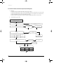
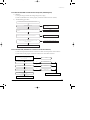
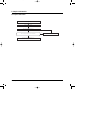
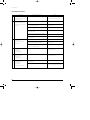
9-00114A(2)-TS
3/8/01 10:04 AM
Page 5-1
5. Troubleshooting
5-1 Items to be checked first
1) The input voltage should be rating voltage ±10% range.
The airconditioner may not operate properly if the voltage is out of this range.
2) Is the link cable linking the indoor unit and the outdoor unit linked properly?
The indoor unit and the outdoor unit shall be linked by 6 cables.
Check the terminals if the indoor unit and outdoor unit are properly linked by the same number of cables.
Otherwise the airconditioner may not operate properly.
3) When a problem occurs due to the contents illustrated in the table below it is a symptom not related to the
malfunction of the airconditioner.
NO
Operation of air conditioner
Explanation
1
The STD operation indication LED blinks when a
power plug of the indoor unit is plugged in for the first time.
It indicates power is on. The LED stops blinking if the operation
ON/OFF button on the remote control unit is pushed.
2
In a COOL operation mode, the compressor does not
operate at a room temperature higher than the setting
temperature that the IN DOOR FAN should operate.
In a HEAT operation mode, the compressor does not
operate at a room temperature lower than the setting
temperature that indoor fan should operate.
In happens after a delay of 3 minutes when the compressor is reoperated. The same phenomenon occurs when a power is on.
As a phenomenon that the compressor is reoperated after a delay of
3 minutes, the indoor fan is adjusted automatically with reference
to a temperature of the air blew
3
Fan speed setting is not allowed in AUTO or DRY mode.
The speed of the indoor fan is set to LL in DRY mode.
Fan speed is 5 steps is selected automatically in AUTO mode.
4
Compressor stops operation intermittently in DRY mode.
Compressor operation is controlled automatically in DRY mode
depending on the room temperature and humidity.
5
Compressor of the outdoor unit is operating although it is
turned off in a HEAT mode.
When the unit is turned off while de-ice is activated, the compressor
continues operation for up to 9 minutes (maximum) until the deice is
completed.
6
Timer LED only of the indoor unit lights up and the
air conditioner does not operate.
Timer is being activated and the unit is in ready mode.
The unit operates normally if the timer operation is cancelled.
7
The compressor and indoor fan stop intermittently in HEAT
mode.
The compressor and indoor fan stop intermittently if room temperature
exceeds a setting temperature in order to protect the compressor from
overheated air in a HEAT mode.
8
Indoor fan and outdoor fan stop operation intermittently in
a HEAT mode.
The compressor operates in a reverse cycle to remove exterior ice in a
HEAT mode, and indoor fan and outdoor fan do not operate intermittently for within 20% of the total heater operation
9
The compressor stops intermittently in a COOL mode or DRY
mode, and fan speed of the indoor unit decreases.
The compressor stops intermittently or the fan speed of the indoor unit
decreases to prevent inside/outside air frozen depending on the
inside/outside air temperature.
4) Indoor unit observes operation condition of the air conditioner, and displays self diagnosis details
on the display panel.
NO
Display
Self Diagnosis
1 STD LED blinking (1Hz)
Restore from power failure (input initial power)
2 TIMER LED blinking (1Hz)
Indoor unit Room sensor Error (open or short)
3 STD and TIMER LED blinking (1Hz)
Indoor unit heat exchanger temperature sensor Error (open or short)
4 BIO LED blinking (1Hz)
Indoor fan malfunctioning (for speed is Below 450rpm)
5 STD, BIO and TIMER LED blinking(IUZ)
EEPROM Error
6 AII LED blinking (1Hz)
Option Error (Option wasn’t setup or option data error)
Samsung Electronics
5-1
9-00114A(2)-TS
3/8/01 10:04 AM
Page 5-2
5-2 Fault Diagnosis by Symptom
5-2-1 No Power (completely dead)-Initial diagnosis
1)
2)
Checklist :
(1) Is input voltage normal? (the rating voltage ±10% range)
(2) Is AC power linked correctly?
(3) Are connections between primary side, secondary side of the power transformer and PCB good.
(4) Is input voltage of DC regulator IC KA7805 (IC02) normal? (11VDC-12.5VDC)
(5) Is input voltage of DC regulator IC KA7805 (IC02) normal? (4.5VDC-5.5VDC)
Troubleshooting procedure
Remove power cord and plug in again
in approx. 5 seconds
Is operation lamp blinking?
NO
YES
Replace PCB
display
YES
Does operation start when
run/stop button on the remote
controller unit pushed?
NO
Is transmission display of the remote
controller unit blinking?
Is DC voltage of PCB
display normal?
NO
Is the input rating ±10%
range applied to the
between #1 and #3 of CN78
NO
NO
•Check linkage between
power cord and
terminal tap
•Check fuse
Is 11~12.5VAC appear in
the input side of the DC
regulator IC KA7805(ICO2)?
NO
YES
NO
Normal
Refer to remote control
unit fault diagnosis
YES
Is "beep"sound heard from the main
unit?
YES
Is DC voltage of the PCB module
normal?
NO
YES
Are voltages of #8 (compressor),
#7 (4 way valve) and #6 (outdoor fan) of
the micom normal? (5VDC)
Is voltage of #60 (indoor fan) of the
micom normal?
DC5V
YES
Refer to Replace
PCB module.
Are voltages at RY71(Compressor)
RY73 (4 way vale) and RY 72 (Outdoor fan)
normal? (DC12V)
Is voltage at SS71(indoor fan)
10ms
YES
Check connections
compressor 4-way
valve, outdoor fan and
indoor fan.
Is voltage at #33 terminal of the Micom normal?
; 0VDC
Is voltage at #18 terminal of the Micom normal?
; 5VDC
Refer to replace
PCB Module
Replace
RY71, RY73,
RY72 and
SS71
NO
YES
Is output voltage of ICO2 normal?(DC5V)
Is voltage at #52 terminal of the micom
normal?
YES
NO
YES
Check PCB pattern. Refer to
Replace nidule PCB.
10ms
NO
NO
YES
NO
Replace ICO2
NO
Are voltage at #48 and #49 of the
micom normal?
Is voltage output terminal of
D101~D105(IN4007) normal?
YES
NO
Replace resonator (X501)
100ms
YES
Is operation normal?
YES
NO
OK
Replace IN4007
Replace
micom
OK
5-2
Samsung Electronics
9-00114A(2)-TS
3/8/01 10:04 AM
Page 5-3
Troubleshooting
5-2-2 When the Indoor Unit Fan Does Not Operate. (Initial Diagnosis)
1)
Checklist :
(1) Is the indoor unit fan motor properly connected with the connector (CN73)?
(2) Is the AC voltage correct?
(3) Is HALL IC in indoor fan motor properly connected with the connector (CN43)?
(4) Is the running capacitor properly connected with the solder part of the PCB?
2)
Troubleshooting procedure
After unplugging out the power cord should
be reconnected within five seconds.
YES
NO
Check as in the procedur “NO power parts” Refer tp
page 5-2.
Does the operating lamp blink?
YES
Does the Solid State Relay(SS71) work
properly?
NO
Microcomputer is out of order.
Test rod location
+
-
SS71+
SS71-
Normal
Voltage
12V
YES
NO
Is the supply voltage of the fan
motor sufficient?
Test rod location
PCB is
out of order.
Normal
voltage
PCB CN73
Condition
Pin 3, Pin 5
Fan operate
.
=. AC 180V
YES
MF-C is out of order
Fan motor
is out of order.
Samsung Electronics
Refer to replace PCB
module
Replace MFC
Fan motor
should be replaced.
5-3
9-00114A(2)-TS
3/8/01 10:04 AM
Page 5-4
Troubleshooting
5-2-3 When the Outdoor Unit Does Not Operate. (Initial Diagnosis)
1)
2)
Checklist :
(1) Is input voltage normal? (the rating voltage ±10% range)
(2) Is the set temperature of the remote control higher than room temperature in COOL mode?
(3) Is the set temperature of the remote control lower than room temperature in HEAT mode?
(4) Is the POWER IN connector (CN78) linked correctly?
(5) Is the outdoor unit properly connected with the TERMINAL BLOCK connector(7P)?
Troubleshooting procedure
After unplugging out the power cord should be reconnected within five seconds.
NO
Does the operating lamp blink
Check as in the procedure "No Power parts"
Refer to page 5-2.
YES
YES
Does the timer lamp blink during operation ?
PCB and Room temperature sensor should be
checked.
Room temperature sensor is
out of order
NO
②
①
Is the power relay RY71 operated by adjusting the room
temperature?
Test rod location
+
IC06 Pin #6
NO ①
PCB is
out of order.
③
Normal
-
Condition
GND
RY71 ON
Refer to replace
PCB module
Voltage
DC 4.8V
NO
Is the rating voltage ±10% range applied relay between
CN78 ① and ③ .
NO
Power relay is
out of order
YES
Power relay should be
replaced.
Outdoor unit is
out of order.
②
①
NO
Is the room sensor normal register?
(25°C → 10KΩ)
10°C
20°C
30°C
17.96k Ω
12.09kΩ
8.3kΩ
YES
③
5-4
Samsung Electronics
9-00114A(2)-TS
3/8/01 10:04 AM
Page 5-5
Troubleshooting
5-2-4 When the UP/DOWN Louver Moter Does Not Operate. (Initial Diagnosis)
1)
2)
Checklist :
(1) Is input voltage normal? (the rating voltage ±10% range)
(2) Is the UP/DOWN louver motor properly connected with the connector (CN61)?
Troubleshooting procedure
Remove power cord and plug in again in approx. 5 seconds.
N
Is operating lamp blinking?
Check as in the procedure "No Power parts".
Refer to page 5-2.
Y
Does operation start when swing button of the remote control unit
pushed?
Y
Normal
N
N
Voltage at pin #1-#4 of micom (ICO4) change?(Squarewave)
Micom (IC04) is faulty.
Y
Volatge at pin #15, #16 of IC06 (KID65003), #10, All of IC05
change?(Squarewave)
N
Driver IC05 (KID65003) or IC06 is faulty.
Y
UP/DOWN louver motor is faulty.
5-2-5 In the Heat mode, When there is no warm air current. Check this first;
(1) Is the set temperature of Remote Control lower than room temperature in Heat mode?
(2) Is the Indoor PCB properly connected with the CN71 and CN78 connector?
After training on, the heating operation should
start in five minutes.
YES
Normal
NO
Is the nunber #7 of Micom (IC04) DC 4.8 V?
NO
Abnormal Micom
YES
Is the munber #12 of IC06 (KID65003) LOW?
NO
Abnormal IC07
YES
Is the voltage between CN71 #5 and CN78 #1 the rating voltage ±10% range?
NO
Abnormal RY73
YES
Abnormal 4way valve of Outdoor Unit.
or connecting Cable
Refer to replace PCB module
4 way valve should be replaced
or connecting Cable Check.
Samsung Electronics
5-5
9-00114A(2)-TS
3/8/01 10:04 AM
Page 5-6
Troubleshooting
5-2-6 If Operation By Remote Control Unit Is Impossible. (Initial Diagnosis)
1)
Troubleshooting procedure
Remove power cord and plug in again approx. 5 Seconds
Is operation lamp blinking?
N
Y
“
“ sound heard from the indoor unit when ON/OFF
button on the remote control unit pushed?
Y
Check as in the procedure “NO Power
parts”. Refer to page 5-2.
Normal
N
Voltage of battery less than 2.5V (Remote Control Unit)?
Y
Replace battery.
N
LCD display status of REMOCON normal?
N
LCD is faulty.
Y
Transmission display lamp (
) blinking when
ON/OFF button on the remote control unit pushed?
N
Replace button.
Y
Voltage at PIN #30 of Remocon Micom change?
N
Micom is faulty.
Y
Voltage at collecter of Q601 or Q602 change?
N
Q601(C4375Y) or Q602(C1623Y) is faulty.
Y
Voltage at pin #26 of micom (IC04) change (INDOOR UNIT)?
IR LED(CL-1L5EU) is faulty.
N
Receiver module is faulty.
Y
Micom (IC04) is faulty.
5-6
Samsung Electronics
9-00114A(2)-TS
3/8/01 10:04 AM
Page 5-7
5-3 Replace PCB module
5-3-1 Replace PCB module
Remove power cord
Replace the PCB module
Check the connection and plug in
NO
Does all display lamp blink or STD lamp blink?
Replace another PCB module
YES
Refer to set up the Model option(5-3-2)
Samsung Electronics
5-7
9-00114A(2)-TS
3/8/01 10:04 AM
Page 5-8
Troubleshooting
5-3-2 Set up the Model option
The Method for Setting up the model option with remocon
¥ It is necessary to set up option code after replacing the main-PBA as a service parts.
Make sure that you can set up the option of code the remote controller after you replace the main
PBA otherwise, the unit wonÕt be working properly and all LED lamps on display will be flickering.
Step 1 : Preparing the remocon to main PBA option set
1st Remove the battery from the remocon.
2nd Press the temperature raise/down button simultaneously
and insert the battery again.
3rd Make sure the remocon display shown as
.
Step 2 : Second stage preparation of the remocon option set.
❈ Note ; In case the wrong letter has been selected, continue to press the button until the correct letter appears.
1st
2nd
3rd
If the first stage number Ò Ó appears on the display, proceed to the second stage.
Every time the ! and & button, Ò Ó and Ò Ó each continue to appear.
Whenever pressing the @, #, $, %, ^, *, (, ), 1, 2 button, the number increase from
0~9(0123456789) and A, b, C, d, E, F each time.
! If the first number is
appear.
5-8
, it is correct otherwise press
until
@ When pressing the
select one of them.
button
~
appear on the display,
# When pressing the
select one of them.
button
~
appear on the display,
$ When pressing the
select one of them.
button
~
appear on the display,
% When pressing the
select one of them.
button
~
appear on the display,
^ When pressing the
select one of them.
button
~
appear on the display,
Samsung Electronics
9-00114A(2)-TS
3/8/01 10:05 AM
Page 5-9
Troubleshooting
! If the first number is
appear.
, it is correct otherwise press
until
@ When pressing the
select one of them.
button
~
appear on the display,
# When pressing the
select one of them.
button
~
appear on the display,
$ When pressing the
select one of them.
button
~
appear on the display,
% When pressing the
select one of them.
button
~
appear on the display,
^ When pressing the
select one of them.
button
~
appear on the display,
Step 3 : Reconfirming option set after completion
(in case of ex. 017d25-17021d)
After pressing
After pressing
selector for the
selector for the
mode, the display shown as
mode, the display shown as
.
.
Step 4 : Pressing the ON/OFF button (
)
When pressing the operation ON/OFF key with the direction of remote controller for unit,
the sound ÒDingÓ or ÒDiriringÓ is heard and the first LED lamp on the left side is flickering at the same time, then the input of option is completed. (If the diriring sound isnÕt
heard, try again pressing the ON/OFF button.)
Step 5 : Unit operation test-run
First, Remove the battery from the remote controller.
Second, Re-insert the battery into the remote controller.
Third, Press ON/OFF key with the direction of remote controller for set.
¥ Error Mode
1st
If all lamps of indoor unit are flickering, Plug out and plug in again and pressing ON/OFF key to retry.
2nd
If the unit is not working properly or all lamps are continuously flickering after setting the option code, see if
the correct option code is set up for itÕs model.
Samsung Electronics
5-9
9-00114A(2)-TS
3/8/01 10:05 AM
Page 5-10
Troubleshooting
■
OPTION ITEMS
REMOCON
SEG1
SEG2
SEG3
SEG4
SEG5
SEG6
SEG7
SEG8
SEG9
SEG10 SEG11 SEG12
AQT24A(B)5(6)RE
0
9
4
6
1
7
1
A
0
2
3
F
SH24TA(B)5
0
9
4
6
1
7
1
A
0
2
3
F
AQT24A(B)6RE
0
8
4
6
1
7
1
A
0
2
3
F
AQT24A(B)6RB
0
8
4
6
1
7
1
A
0
2
3
F
AST24A(B)5RE
0
9
0
0
0
0
1
A
0
2
3
F
SC24TA(B)5
0
9
0
0
0
0
1
A
0
2
3
F
AST24A(B)6RE
0
8
0
0
0
0
1
A
0
2
3
F
AST24A(B)6RB
0
8
0
0
0
0
1
A
0
2
3
F
AQT18A(B)9RE
0
9
7
4
1
7
1
A
0
0
F
B
AQT18A(B)0RE
0
8
7
4
1
7
1
A
0
0
F
B
AQT18A(B)0RB
0
8
7
4
1
7
1
A
0
0
F
B
AQ18A(B)9RE
0
9
4
4
1
7
1
A
0
2
1
D
SH18ZA(B)9
0
9
4
4
1
7
1
A
0
2
1
D
AQ18A(B)0RE
0
8
4
4
1
7
1
A
0
2
1
D
AST18A(B)9RE
0
9
0
0
0
0
1
A
0
0
F
B
AST18A(B)0RE
0
8
0
0
0
0
1
A
0
0
F
B
AST18A(B)0RB
0
8
0
0
0
0
1
A
0
0
F
B
AS18A(B)9RE
0
9
0
0
0
0
1
A
0
2
1
D
SC18ZA(B)9
0
9
0
0
0
0
1
A
0
2
1
D
AS18A(B)0RE
0
8
0
0
0
0
1
A
0
2
1
D
MODEL
5-10
Samsung Electronics
9-00114A(2)-TS
3/8/01 10:05 AM
Page 5-11
5-4 PCB Inspection
5-4-1 Cautions for Part Replacement
1. The human body carries much static
electricity. Before touching a part for repair,
replacement or the similar purpose, be sure
to touch a grounded metallic portion by
hand to let the static electricity go through
the metallic portion to the earth.
Especially when handling any micro
computer or IC, carefully remove such static
electricity before touching them.
2. When repairing any part on a work bench,
be sure to place an insulative sheet on the
bench and always keep the sheet surface
neat without any metal fragments. If any
such fragment touches a part, a secondary
trouble will possibly be caused in the part.
3. Before replacing any parts, be sure to turn
off the power supply. If such replacement is
done with the power supply kept on, an
electric shock, short circuit or destruction of
a part may result.
4. During replacement or repair of a part,
carefully handle it : The printed circuit
board has fine lead wires (jumper wires) and
glass-made parts (diode) on its substrate.
So if a circuit board is roughly handled, such
lead wires and parts will be easily broken or
damaged by bending or shock.
5. When soldering the lead wires of any new
part, be sure to polish them using an emery
paper or the like before solding them.
Since the lead wires of any new part are
covered with an oxide film, solder cannot
adhere to the lead wires if not polished.
6. When soldering any part, care should be
exercised not to apply any high-wattage
soldering iron to the part for a long time.
Some parts are of so low a heat resistance
that they may be broken or have the
properties changed if a soldering iron is so
applied (Otherwise, the pattern may
possibly be separated and raised).
7. The heat of the soldering iron should be
transfered to the entire object to be soldered.
If the solder pieces are not well fused due to
insufficient transfer of the heat from the
soldering iron, no satisfactory electrical
continuity can be assured even if the
soldered objects appear well connected to
each other.
8. The solder used should be limited to a
minimum. If excessive solder is used, it will
cause inter-pattern contact, which may
cause malfunction of the circuit.
5-4-2 Procedure
The parts should be replaced in the following procedure.
Check for any faulty part.
Detach the faulty part.
Replace it with a new part.
Check the operation of the new part.
The repair is completed.
Samsung Electronics
5-11
9-00114A(2)-TS
3/8/01 10:05 AM
Page 5-12
Troubleshooting
5-4-3 Detailed Procedure
Checking point (symptoms)
No.
Malfunction
1
Pull out the power plug from the
AC terminal and confirm the fuse
on the PCB assembly
1. Is the broken?
2
Turn the power on.
If lamp blinks trouble is not
related to the items 1 through 4
on the right.
Voltage check
1. AC voltage at both end of transformer Primary?
; rating voltage ±10% range
Causes
1. Voltage over
2. Indoor unit fan motor short-circuit.
1. Irregular power code or power fuse,
or poor wiring.
2. Transformer is faulty.
3
Set operating mode when RMC
switch pushed.
Except for [FAN]mode and
[TIMER] mode.
3. DC voltage at OUT and GND of IC01
(KA7812)? ; 12VDC
3. Power circuit is faulty.
4. DC voltage at OUT and GND of IC02? ; 5VDC
4. Power circuit is faulty.
5. DC voltage at Q201 Base and GND change?
; squarewave
5. Q201 is faulty.
Voltage check
1. Voltage of relay (RY71) coil Voltage at
PIN#11, PIN#12, PIN#15 of IC07 ; 12VDC
1. Relay(RY 71) coil is open.
IC07 is faulty.
2. Voltage at CN78 #1 and CN78
#5 ; rating voltage ±10% range
2. Relay(RY 71) contactor is faulty.
4
Set operating mode when RMC
switch pushed.
1. COOL mode
2. TURBO operating
1. Compressor does not operate.
1. PCB is faulty.
2. Connecting is faulty.
5
Set operating mode when
RMC switch pushed.
1. HEAT mode
2. TURBO operating
1. Compressor does not operate
1. PCB is faulty.
2. Connecting is faulty.
6
Set operating mode when
RMC switch pushed.
1. [FAN] mode
2. Fan speed [Hi]
3. Continuously operation
1. Voltage at # % both ends of CN73 :
above 180V~
1. Indoor unit fan motor is faulty.
2. Indoor unit fan motor does not operate.
2. Poor connection of indoor fan motor
and connector of RPM sensing (CN43)
5-12
Samsung Electronics
9-00114A(2)-TS
3/8/01 10:05 AM
Page 5-13
MEMO
Samsung Electronics
5-13