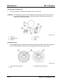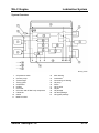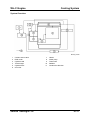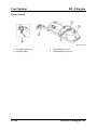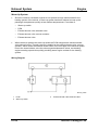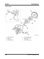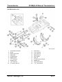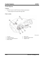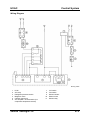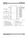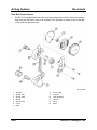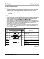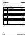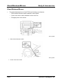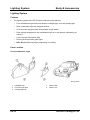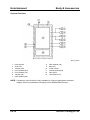
1
Training Manual
Mazda BT-50
NMT-009
No part of this hardcopy may be reproduced in any form without prior permission of
Mazda Motor Europe GmbH.
The illustrations, technical information, data and descriptive text in this issue, to the best of our
knowledge, were correct at the time of going to print.
No liability can be accepted for any inaccuracies or omissions in this publication, although every
possible care has been taken to make it as complete and accurate as possible.
© 2006
Mazda Motor Europe GmbH
Training Services
Table of Contents
General Information ..........................................................................00-1
Product Concept....................................................................................................00-1
Vehicle Identification Number................................................................................00-7
Engine Identification Number ................................................................................00-8
Other Vehicle Information Labels ..........................................................................00-9
Model Plate.....................................................................................................00-9
Tyre Pressure Label .......................................................................................00-9
Technical Data.....................................................................................................00-10
Jacking and Lifting...............................................................................................00-11
Towing .................................................................................................................00-12
Scheduled Maintenance Table ............................................................................00-13
Remarks .......................................................................................................00-15
WL-C Engine ......................................................................................01-1
Engine Performance Curve ...................................................................................01-1
Overview................................................................................................................01-2
Mechanical ..................................................................................................................01-3
Features ................................................................................................................01-3
Specifications ........................................................................................................01-3
Piston.....................................................................................................................01-4
Cylinder Head........................................................................................................01-5
Parts Location.................................................................................................01-5
Valve Gear......................................................................................................01-7
Valve-Clearance Adjustment ..........................................................................01-8
Camshaft Pulleys............................................................................................01-8
Timing Belt Auto Tensioner ............................................................................01-9
Engine Timing...............................................................................................01-10
Lubrication System ..................................................................................................01-11
Features ..............................................................................................................01-11
Specifications ......................................................................................................01-11
Parts Location......................................................................................................01-12
System Overview.................................................................................................01-13
Oil Filter ...............................................................................................................01-14
Cooling System ........................................................................................................01-15
Features ..............................................................................................................01-15
Specifications ......................................................................................................01-15
Parts Location......................................................................................................01-16
System Overview.................................................................................................01-17
Intake-Air System .....................................................................................................01-18
Features ..............................................................................................................01-18
Parts Location......................................................................................................01-19
System Overview.................................................................................................01-20
MAF Sensor.........................................................................................................01-21
MAF Learning Function .......................................................................................01-21
MAF Data Reset ..................................................................................................01-21
MAP Sensor / IAT Sensor No.1...........................................................................01-21
Variable Geometry Turbocharger ........................................................................01-22
Intake Manifold ....................................................................................................01-23
Variable Swirl Control Shutter Valves...........................................................01-24
Vacuum Chamber................................................................................................01-24
Service Training BT-50
Table of Contents
Fuel System ..............................................................................................................01-25
Features ..............................................................................................................01-25
Specifications ......................................................................................................01-25
Parts Location......................................................................................................01-26
System Overview.................................................................................................01-28
High-Pressure Pump ...........................................................................................01-29
Common Rail.......................................................................................................01-29
Fuel Injectors .......................................................................................................01-30
Exhaust System........................................................................................................01-31
Features ..............................................................................................................01-31
Parts Location......................................................................................................01-31
Warm up system..................................................................................................01-32
Wiring Diagram.............................................................................................01-32
Exhaust Shutter Valve Solenoid Valve .........................................................01-33
Exhaust Shutter Valve Unit...........................................................................01-33
Operating Conditions....................................................................................01-33
Emission System......................................................................................................01-34
Features ..............................................................................................................01-34
Parts Location......................................................................................................01-34
System Overview.................................................................................................01-36
EGR Solenoid Valve............................................................................................01-37
EGR Control ........................................................................................................01-37
Intake Shutter Valve ............................................................................................01-38
Charging and Starting System ................................................................................01-39
Parts Location......................................................................................................01-39
Control System .........................................................................................................01-40
Features ..............................................................................................................01-40
Specifications ......................................................................................................01-40
Parts Location......................................................................................................01-41
System Overview.................................................................................................01-42
Block Diagram .....................................................................................................01-44
Relationship Chart ...............................................................................................01-45
Crankshaft Position Sensor .................................................................................01-46
Camshaft Position Sensor ...................................................................................01-47
Powertrain Control Module ..................................................................................01-48
Features .......................................................................................................01-48
A/C Cut-Off Control ......................................................................................01-49
Glow Plug Relay ...........................................................................................01-50
On-Board Diagnostic System ..............................................................................01-51
Features .......................................................................................................01-51
Malfunction Indicator Lamp ..........................................................................01-51
Self Test .......................................................................................................01-51
PID Monitor..........................................................................................................01-52
Simulation Test....................................................................................................01-53
Maintenance and Repair .....................................................................................01-54
MAF Sensor Learning Function....................................................................01-54
Replacing the MAF Sensor...........................................................................01-54
PCM Replacement .......................................................................................01-55
Service Training BT-50
Table of Contents
Suspension ........................................................................................02-1
Features ................................................................................................................02-1
Specifications ........................................................................................................02-1
Parts Location........................................................................................................02-2
Front Suspension 2WD ..................................................................................02-2
Front Suspension 4WD ..................................................................................02-2
Rear Suspension ............................................................................................02-3
Wheels and Tyres .......................................................................................................02-4
Specifications ........................................................................................................02-5
Driveline / Axle...................................................................................03-1
Features ................................................................................................................03-1
Specifications ........................................................................................................03-1
RFW System .........................................................................................................03-2
Parts Location.................................................................................................03-2
System Overview............................................................................................03-3
On-Board Diagnostic System .........................................................................03-4
Transmission .....................................................................................05-1
Clutch ..........................................................................................................................05-1
Features ................................................................................................................05-1
Specifications ........................................................................................................05-1
Parts Location........................................................................................................05-2
Clutch Master Cylinder ..........................................................................................05-3
Dual Mass Flywheel ..............................................................................................05-4
S15M(X)-D Manual Transmission..............................................................................05-5
Features ................................................................................................................05-5
Specifications ........................................................................................................05-6
Overview................................................................................................................05-7
Power Flow............................................................................................................05-8
Shift Mechanism ..................................................................................................05-10
Shift Mechanism Unit....................................................................................05-11
5th / Reverse Gear Mechanism .....................................................................05-12
Reverse Gear Lockout Mechanism ..............................................................05-14
HVAC ..................................................................................................07-1
Basic System ..............................................................................................................07-1
Features ................................................................................................................07-1
Specifications ........................................................................................................07-1
Parts Location........................................................................................................07-2
Refrigerant System................................................................................................07-3
Control System ...........................................................................................................07-4
Features ................................................................................................................07-4
Parts Location........................................................................................................07-4
Wiring Diagram......................................................................................................07-5
Climate Control Unit ..............................................................................................07-6
Service Training BT-50
Table of Contents
Restraints...........................................................................................08-1
Airbag System ............................................................................................................08-1
Features ................................................................................................................08-1
Parts Location........................................................................................................08-2
Wiring Diagram......................................................................................................08-3
SAS Control Module ..............................................................................................08-4
Side Airbag Sensors..............................................................................................08-5
Side Airbags ..........................................................................................................08-5
Seat Belt Pretensioners.........................................................................................08-6
On-Board Diagnostic System ................................................................................08-7
Features .........................................................................................................08-7
Self Test .........................................................................................................08-7
PID Monitor.....................................................................................................08-8
Body & Accessories..........................................................................09-1
Body Panels ................................................................................................................09-1
Cabin .....................................................................................................................09-1
Ladder Frame ........................................................................................................09-2
Cargo Box..............................................................................................................09-3
Anti-Corrosion Measures.......................................................................................09-3
Glass/Windows/Mirrors..............................................................................................09-4
Security and Locks.....................................................................................................09-5
Features ................................................................................................................09-5
Theft Deterrent System .........................................................................................09-5
Wiring Diagram...............................................................................................09-6
Exterior Trim ...............................................................................................................09-7
Features ................................................................................................................09-7
Parts Location........................................................................................................09-7
Front and Rear Bumper.........................................................................................09-8
Interior Trim ................................................................................................................09-9
Features ................................................................................................................09-9
Parts Location........................................................................................................09-9
Lighting System........................................................................................................09-10
Features ..............................................................................................................09-10
Parts Location......................................................................................................09-10
Front Combination Light ...............................................................................09-10
Rear Combination Light................................................................................09-11
Overview..............................................................................................................09-12
Daytime Running Light ........................................................................................09-12
Wiring Diagram....................................................................................................09-13
Wiper / Washer System............................................................................................09-14
Features ..............................................................................................................09-14
Parts Location......................................................................................................09-14
Wiring Diagram....................................................................................................09-15
Service Training BT-50
Table of Contents
Audio System............................................................................................................09-16
Features ..............................................................................................................09-16
Specifications ......................................................................................................09-16
Audio Unit .....................................................................................................09-16
Speakers ......................................................................................................09-16
Parts Location......................................................................................................09-17
System Overview.................................................................................................09-18
On-Board Diagnostic System ..............................................................................09-20
Self-Test Function ........................................................................................09-20
Diagnostic Assist Function ...........................................................................09-20
Power Systems .........................................................................................................09-21
Parts Location......................................................................................................09-21
Instrumentation / Driver Information System ........................................................09-22
Features ..............................................................................................................09-22
Specifications ......................................................................................................09-22
Instrument Cluster Overview ...............................................................................09-23
Key Reminder Warning Alarm .............................................................................09-24
Input / Output Check Mode..................................................................................09-24
Control System .........................................................................................................09-25
Features ..............................................................................................................09-25
Data Link Connector............................................................................................09-25
Wiring Diagram....................................................................................................09-26
Service Training BT-50
Table of Contents
Notes:
Service Training BT-50
General Information
General Information
Product Concept
•
The new Mazda BT-50 supersedes the B-Series, Mazda’s present pick-up truck. The
aim of the BT-50 development team was to create a new pickup model in line with the
current model range delivering Mazda’s Zoom-Zoom spirit in its individual and distinctive
way.
•
The BT-50 has inherited the tough and reliable commercial truck performance of the BSeries. Simultaneously it presents a new fresh body styling and technologies that
customers enjoy on passenger cars and also demand more and more for pick-up trucks.
•
The BT-50 is offered with RWD (Rear Wheel Drive) layout as 2WD or as manually
activated part-time 4WD.
BT-50_00001
Service Training BT-50
00-1
General Information
•
Plane body panels without the formerly used swage lines and other new styling elements
contribute to a more brawny, but clear and modern overall styling impression.
BT-50_00002
BT-50_00022
00-2
Service Training BT-50
General Information
•
The design and material quality of the interior has been improved and now reminds more
of a passenger car than of a pick-up truck.
BT-50_00003
•
Beside the clearly arranged instrument panel the completely new T-shaped dashboard
contains a centre stack panel incorporating the latest modular audio system and the
climate control panel, both with easy to operate control elements.
BT-50_00004
Service Training BT-50
00-3
General Information
•
New features of the powertrain, such as the 16-valve DOHC-diesel engine with common
rail direct injection and Euro 4 emission standard, the dual-mass flywheel or the 5-speed
transmission S15M(X)-D contribute to a driving performance and emission output that
are comparable to passenger cars.
•
The noise level emitted by the engine has been significantly reduced by the common rail
injection system and additionally dampened by broad use of insulation materials.
BT-50_00005
00-4
Service Training BT-50
General Information
•
Other well-proven components, which are adopted from the B-Series as e.g. the chassis
with the ladder frame and the suspension, are refined by major or minor changes in
material, form, and/or dimension.
BT-50_00006
•
The supplemental restraint system is now enhanced by combined head / side airbags as
used on the MX-5 (NC).
BT-50_00007
Service Training BT-50
00-5
General Information
•
The BT-50 is basically offered in three different body versions:
–
REG (REGular) Cabin, available in 2WD or 4WD layout
BT-50_00008
–
RAP (Rear Access Panel) Cabin (marketing name is ‘Freestyle Cab’), available in
4WD layout
BT-50_00009
–
DBL (DouBLe) Cabin, available in 4WD layout
BT-50_00010
00-6
Service Training BT-50
General Information
Vehicle Identification Number
•
The VIN is located on the outside of the right chassis member (visible from the right front
wheel arch). The model code of the BT-50 has remained ‘UN’, while the serial number
starts at 600,001.
BT-50_00011
JMZ UN 1
A
1
2
0 W
600001
Serial No.
Plant W= Auto Alliance Thailand
Dummy 0
Transmission 2 = 5 speed MTX
Engine Type 1 = WL-C (2.5 L)
B = REG cab (A)*
F = DBL cab (E)*
Body style 2 = RAP cab (1)*
1 = 2WD
Drive axle 8 = 4WD
Vehicle type UN = Mazda BT-50
World manufacturer indication JMZ = European (L.H.D., U.K.)
* without cargo box
Service Training BT-50
BT-50_T00001
00-7
General Information
Engine Identification Number
•
The engine identification number of the WL-C engine is located on the timing gear-side
of the cylinder block.
BT-50_00012
00-8
Service Training BT-50
General Information
Other Vehicle Information Labels
Model Plate
•
The model plate is located on the right side of the bulkhead in the engine compartment.
BT-50_00013
1
Driving direction
Tyre Pressure Label
•
The tyre pressure label is located on the driver’s door as shown below.
BT-50_00014
Service Training BT-50
00-9
General Information
Technical Data
Item
Unit
REG
2WD
Overall length (w/o rear step bumper)
Overall width (AWD models with Overfenders)
1,715
Overall height (unladen)
1,620
Front track
mm
1,450
Wheelbase
Ground clearance (unladen)
Maximum fording depth
Angle of approach (unladen)
Angle of departure (unladen)
Minimum turning circle (wall-to-wall)
2,985
181
300
24
26
12
*1
P235/75R15
*2
m
5,075
1,805
*1
1,745
2
1,750 *
*1
1,445
*2
1,495
*1
1,440
*2
1,470
3,000
207
450
32
27
12.6
1,445
Rear track
°
RAP
4WD
DBL
*1
1,755
2
1,760 *
BT-50_T00002
245/70R16
Item
REG
Maximum Weight (kg)
RAP
4WD
1,798
1,886
DBL
Curb weight
2WD
1,587
Gross vehicle weight
2,795
3,010
3,080
3,030
Front
1,170
1,430
1,430
1,430
Rear
1,860
1,850
1,850
1,850
Gross axle weight
Max.trailing load
750
unbraked
braked
1,895
1,600
3,000
BT-50_T00004
Item
Engine type
Displacement
Bore x stroke
Compression ratio
Max. power
Max. torque
Emission standard
Transmission
2.5 MZR-CD (WL-C) Engine
Inline 4 Cyl., DOHC 16-valve, Turbocharged w.Intercooler
2,499 cm3
93 x 92 mm
18.0 : 1
105 kW (143 PS) at 3,500 min-1
330 Nm at 1,800 min-1
Euro 4
5-speed manual (S15M(X)-D)
BT-50_T00005
00-10
Service Training BT-50
General Information
Jacking and Lifting
•
The front of the vehicle can be lifted with a jack near the centre of the front
crossmember.
NOTE: The jacking point on the front axle for the 2WD is different to the 4WD model.
BT-50_00023
1
2
only 2WD
only 4WD
Service Training BT-50
3
2WD and 4WD
00-11
General Information
Towing
•
The towing hooks on the 2WD model are different from the 4WD model.
BT-50_00020
2WD
1
•
Towing hooks
The 4WD model has two tie-down hooks that may not be used for towing. The towing
hook is located on the left side.
BT-50_00021
4WD
1
Towing hook
00-12
2
Tie-down hooks
Service Training BT-50
General Information
Scheduled Maintenance Table
Maintenance Interval
Number of months or kilometers (miles), whichever comes first
Months
12
24
36
48
60
72
84
96
108
x1000 km
20
40
60
80
100
120
140
160
180
x1000 miles
12.5
25
37.5
50
62.5
75
87.5
100 112.5
ENGINE
Engine valve clearance
Engine timing belt
I
Replace every 120,000 km (75,000 miles)
Engine timing belt auto tensioner*
Engine oil
1
Replace every 120,000 km (75,000 miles)
*2
*2
Engine oil filter
Drive belts
I
*1
*3
R
R
R
R
R
R
R
R
R
R
R
R
R
R
R
R
R
R
I
I
I
I
I
I
I
I
I
COOLING SYSTEM
Cooling system (including coolant level
adjustment)
FL22 type
Engine coolant
I
*4
I
I
I
Replace every 200,000 km (125,000 miles) or 11 years
Replace first at 100,000 km (62,500 miles) or 4 years;
after that every 2 years
Others
FUEL SYSTEM
*5
Air cleaner element
Fuel filter
Fuel lines and hoses
C
R
I
C
R
I
C
I
C
R
I
I
I
C
I
R
R
I
I
I
I
I
R
I
C
R
I
I
I
I
I
I
I
I
I
I
I
I
I
I
EMISSION CONTROL SYSTEM
Air intake system
ELECTRICAL SYSTEM
Battery electrolyte level and specific gravity
BT-50_T00006
Service Training BT-50
00-13
General Information
Maintenance Interval
Number of months or kilometers (miles), whichever comes first
Months
12
24
36
48
60
72
84
96
108
x1000 km
20
40
60
80
100
120
140
160
180
x1000 miles
12.5
25
37.5
50
62.5
75
87.5
100 112.5
CHASSIS and BODY
Brake lines, hoses and connections
*6
Brake fluid
Parking brake
I
I
R
I
Brake booster and hoses
Disc brakes
I
I
R
I
I
I
I
R
I
I
I
I
Inspect every 200,000 km (125,000 miles)
*7
I
*7
Drum brakes
Power steering fluid, lines, hoses and
connections
Steering operation and linkages
I
I
I
I
I
I
I
I
I
I
I
I
I
I
R
Rear differential oil (2WD)
I
R
I
Transfer oil (4x4)
Drive shaft dust boots (4WD)
I
I
I
Propeller shaft joints (4WD)
L
Front and rear suspension and ball joints
R
I
*8
Wheel bearing axial play
Bolts and nuts on chassis and body
I
I
R
I
I
I
R
R
I
I
R
I
I
I
I
R
I
I
I
I
L
L
I
I
I
I
R
I
R
I
I
I
I
R
I
I
R
I
I
I
Inspect every 80,000 km (50,000 miles) or 5 years
T
T
T
Body condition (for rust, corrosion and
perforation)
Tyres (including spare tyre ) with inflation
pressure adjustment
I
I
I
I
I
L
R
Exhaust system and heat shields
I
I
I
Front and rear differential oil (4WD)
I
I
Manual transmission oil
Front wheel bearing grease (2WD)
I
R
I
T
T
T
T
T
T
I
I
I
Inspect annually
I
I
I
I
I
I
BT-50_T00007
Chart symbols
I: Inspect: Inspect and clean, repair, adjust, or replace if necessary.
R: Replace
T: Tighten
L: Lubricate
C: Clean
00-14
Service Training BT-50
General Information
Remarks
•
Refer below for a description of items marked with * in the maintenance chart.
–
*1: Replacement of the engine timing belt and auto tensioner is required at every
120,000 km (75,000 miles). Failure to replace the timing belt and the auto tensioner
may result in damage to the engine.
–
*2: If the vehicle is operated primarily under any of the following conditions, replace
the engine oil and oil filter more often than the recommended intervals.
a) Driving in dusty conditions
b) Extended periods of idling or low speed driving
c) Driving for long periods in cold temperatures or driving regularly at short
distance (less than 8 km/ 5 miles) only
*
–
3: Also inspect and adjust the power steering and air conditioner drive belts, if
installed.
–
*
4: Use FL22 type coolant in vehicles with the inscription ‘FL22’ on the radiator cap
itself or the surrounding area. Use FL22 when replacing the coolant.
–
*
5: If the vehicle is operated in very dusty or sandy areas, clean the air cleaner
element at every 10,000 km (6,250 miles) or 6 months. Replace the air cleaner
element at every 30,000 km (18,750 miles) or 18 months.
–
*
6: If the brakes are used extensively (for example, continuous hard driving or
mountain driving) or if the vehicle is operated in extremely humid climates, replace
the brake fluid annually.
–
*
7: If the vehicle is operated primarily under any of the following conditions, inspect
the disc brakes and drum brakes more often than the recommended intervals.
a) Driving on bumpy roads, gravel roads, snowy roads or unpaved roads
b) Driving uphill and downhill frequently
c) Repeated short-distance driving
–
*
8: If the vehicle is operated primarily under any of the following conditions, replace
the front wheel bearing grease at every 20,000 km (12,500 miles) or 12 months.
a) Driving in dusty conditions
b) Driving in rough, muddy or snow-melted conditions
c) Towing a trailer
Service Training BT-50
00-15
General Information
Notes:
00-16
Service Training BT-50
Engine
WL-C Engine
WL-C Engine
•
The BT-50 is offered with the 2.5 L common rail diesel engine, which has the
identification code WL-C.
•
The design and operation of the WL-C engine are essentially carried over from that of
the B-Series with WLT-3 engine, except for the new features described in the respective
sections.
NOTE: Further information can be found in the Training Manual of the ‘B-Series’ (NMT-005)
and in ‘Basic Diesel Engine Management’ (CT-L2005) and ‘Advanced Diesel Engine
Management’ (CT-L3004).
Engine Performance Curve
BT-50_01001
X
Y1
Y2
Engine speed
Engine power
Engine torque
Service Training BT-50
1
2
Power curve
Torque curve
01-1
WL-C Engine
Engine
Overview
BT-50_01002
01-2
Service Training BT-50
WL-C Engine
Mechanical
Mechanical
Features
•
The mechanical system of the WL-C engine has the following new features:
–
–
–
–
–
–
–
–
Pistons with integrated combustion chamber
Coated piston skirt
Reduced compression ratio
Newly constructed aluminium alloy cylinder head
Double overhead camshafts (driven by a timing belt)
Four valves per cylinder
Adjustable roller-type rocker arms
Timing belt auto tensioner
Specifications
Item
Specification
WL-C
Type
Diesel 4-stroke
Cylinder arrangement and number
Inline, 4-cylinder
Combustion chamber
Direct injection
Valve system
DOHC, timing gear and belt driven, 16 valves
Displacement
ml
2,499
Bore x stroke
mm
93.0 x 92.0
Compression ratio
18.0:1
Compression pressure
kPa
2,942 (standard)
2,648 (minimum)
Open BTDC (°)
10
IN
Close ABDC (°)
30
Valve timing
Open BBDC (°)
40
EX
Close ATDC (°)
8
Valve clearance
IN
mm
0.10-0.16
(engine cold)
EX
mm
0.17-0.23
BT-50_T01001
Service Training BT-50
01-3
Mechanical
WL-C Engine
Piston
•
In accordance with the adoption of the common rail injection system, the piston head
shape now incorporates the combustion chamber. Due to the modified piston shape the
compression ratio is reduced from 21.6: 1 on the WLT-3 engine to 18.0: 1.
•
A reduction of the internal friction and hence of the engine’s mechanical loss has been
achieved by coating of the piston skirt area.
NOTE: The piston side marked with ‘F’ must be installed towards the timing gear-side of the
engine.
BT-50_01006
1
2
Combustion chamber
Cooling oil channel
3
Piston skirt coating
NOTE: Oversize bearings for the crankshaft and connecting rods, as well as oversize
pistons are available in various dimensions (refer to Engine W/M).
01-4
Service Training BT-50
WL-C Engine
Mechanical
Cylinder Head
Parts Location
BT-50_01007
1
2
3
4
Cylinder head cover
Upper camshaft bearing caps
Lower camshaft bearing case with
injector sealing rings
Cylinder head
Service Training BT-50
5
6
7
Cylinder head gasket
Seal plate
Camshaft pulley
8
Camshaft
01-5
Mechanical
WL-C Engine
•
The cylinder head and the full floating cylinder head cover are made of aluminium alloy.
•
The steel laminated cylinder head gasket is available in three different thicknesses
depending on the piston protrusion. The gasket is marked respectively (refer to Engine
W/M).
•
The camshafts are supported in a separate bearing case, which is available as a
separate spare part.
•
For lubrication of the cam lobes, bearings / journals and rocker arms, the camshafts are
hollow and have oil bores at each lubricating point.
BT-50_01008
A
B
1
2
Exhaust camshaft
Intake camshaft
Thrust force bearing boss
Oil bore
3
4
5
Oil passage
Location of cylinder no.1
Hexagonal shaped surface
NOTE: The cylinder head surface must not be machined. If necessary, the cylinder head
must be replaced (refer to Engine W/M).
01-6
Service Training BT-50
WL-C Engine
Mechanical
Valve Gear
•
The valve gear comprises helical gears and a timing belt
•
The timing belt drives two camshafts and is adjusted by an auto tensioner.
•
Adjustable roller type rocker arms have been adopted to lower the friction between
camshaft lobe and rocker arm, reducing the engine’s mechanical loss.
BT-50_01009
1
2
3
4
Camshaft pulley
Camshaft
Rocker arm
Balancer shaft
5
6
7
Helical gear
Timing belt auto tensioner
Timing belt
NOTE: The construction of the helical gears and their adjustment procedure is identical to
that of the WLT-3 engine (refer to the engine W/M).
Service Training BT-50
01-7
Mechanical
WL-C Engine
Valve-Clearance Adjustment
•
The valve clearance is measured between roller and cam lobe.
CAUTION: For loosening the locknut of the adjusting screw the cam lobe must push down
the rocker arm firmly as shown in the figure below. Otherwise the claw of the
rocker arm might be damaged.
BT-50_01010
1
2
3
Cam lobe
Adjusting screw
Locknut
4
5
6
Rocker arm
Claw
Roller
Camshaft Pulleys
•
The camshaft pulleys for intake and exhaust camshaft are identical. They are positioned
on the camshaft with pins and have to be installed as shown in the figure below.
BT-50_01011
1
2
01-8
Intake side camshaft pulley
Pin
3
Exhaust side camshaft pulley
Service Training BT-50
WL-C Engine
Mechanical
Timing Belt Auto Tensioner
•
A timing belt auto tensioner has been adopted to maintain timing belt tension constant.
The timing belt tension is released by turning the auto tensioner counterclockwise with
the aid of an Allen wrench (with max. 39 Nm apply force). The turned back tensioner is
secured by inserting a fixing pin with 6 mm diameter into the appropriate bore (No. 3 in
figure below).
BT-50_01055
1
2
Apply force (max. 39 Nm)
Mounting bolts (C+B)
3
Hole for fixing pin
BT-50_01014
1
2
3
Rod
Seal
Plunger
4
5
6
Spring
Oil
Ball
NOTE: In case air has entered the pressure chamber of the auto tensioner, it must be bled
using a certain procedure (refer to W/M).
Service Training BT-50
01-9
Mechanical
WL-C Engine
Engine Timing
•
When replacing the timing belt the timing marks must be positioned as shown in the
figure below.
BT-50_01013
1
2
Intake camshaft pulley
Exhaust camshaft pulley
01-10
3
4
Timing mark
High-pressure pump pulley
Service Training BT-50
WL-C Engine
Lubrication System
Lubrication System
Features
•
The lubrication system of the WL-C engine has the following new features:
–
–
–
Plastic oil strainer with resin filter
Spin-on type oil filter with full-flow paper element
Double layer oil pan with additional oil baffle
Specifications
Specification
WL-C
Item
Type
Force-fed type
Oil pressure (reference values)
[after warm up]
(at idle) kPa
100-330
(at 2,500 rpm)
kPa
410-570
Type
Relief valve
Oil pump
opening pressure
(reference value)
Type
Oil cooler
Oil cooler bypass valve opening
pressure
Type
Oil filter
Bypass pressure
Total (dry engine)
Oil capacity
Oil replacement
(approx.
Oil and oil filter
quantity)
replacement
Grade
Viscosity (SAE)
Remarks
Gear type
kPa
580-700
Water-cooled
kPa
164-200
Full-flow paper element, spin-on type
kPa
80-120
8.0
L
6.8
7.0
API CF or ACEA B1/B3/B5
5W-30
e.g. Mazda genuine Dexelia oil
BT-50_T01003
Service Training BT-50
01-11
Lubrication System
WL-C Engine
Parts Location
BT-50_01044
1
2
3
4
5
6
Oil jet valve
Oil pressure switch
Oil dipstick
Oil cooler
Oil filter body
Oil filter
01-12
7
8
9
10
11
12
Oil cooler and oil filter body component
Oil pan
Oil drain plug
Oil strainer
Oil outlet pipe
Oil pump
Service Training BT-50
WL-C Engine
Lubrication System
System Overview
BT-50_01015
1
2
3
4
5
6
7
8
9
10
11
Oil pressure switch
Vacuum pump
Turbocharger
Timing gears
Oil Strainer
Oil filter
Oil cooler
Oil cooler and oil filter body component
Camshaft
Orifice
Balancer shaft
Service Training BT-50
12
13
14
15
16
17
18
19
20
21
Main bearing
Crankshaft
Connecting rod bearing
Oil pump
Piston
Oil jet valve
Oil pan
Oil passage
Oil relief passage
Oil bypass passage
01-13
Lubrication System
WL-C Engine
Oil Filter
•
The spin-on type oil filter consists of one full flow element. The bypass element that has
been additionally used on the filter WLT-3 engine has been dropped.
BT-50_01017
1
Full-flow paper element
01-14
Service Training BT-50
WL-C Engine
Cooling System
Cooling System
Features
•
The cooling system of the WL-C engine has the following new features:
–
–
Longlife engine coolant FL-22
Asymmetric positioned radiator fan blades for noise reduction (thermo-modulated
fan-type)
Specifications
Specification
WL-C
Item
Type
Type
Water-cooled, forced circulation
Without heater: 8.8
With heater: 9.4
Centrifugal, V-belt driven
Type
Wax, bottom-bypass
Coolant capacity (approx. quantity)
Water pump
Thermostat
Radiator
Cooling system
cap
L
Opening temperature
Full-open temperature
Full-open lift
Type
°C
°C
mm
80-84
95
8.5 or more
Corrugated fin
Cap valve opening pressure
kPa
93.2-122.6
Type
Cooling fan
Number of blades
Outer diameter
Thermo-modulation type
mm
9
450
BT-50_T01005
Service Training BT-50
01-15
Cooling System
WL-C Engine
Parts Location
BT-50_01045
1
2
3
4
Radiator cowling
Water pump pulley
Thermostat
Water pump
5
6
7
8
Cooling fan
Coolant reserve tank
Radiator
Cooling system cap
NOTE: To bleed the cooling system follow the instructions of the W/M.
01-16
Service Training BT-50
WL-C Engine
Cooling System
System Overview
BT-50_01018
1
2
3
4
5
6
Coolant reserve tank
EGR cooler
Cylinder head
Turbocharger
Cylinder block
Oil cooler
Service Training BT-50
7
8
9
10
11
Heater
Water pump
Thermostat
Radiator
Coolant flow direction
01-17
Intake-Air System
WL-C Engine
Intake-Air System
Features
•
The intake-air system of the WL-C engine has the following new features:
–
–
Newly designed air cleaner housing with dry filter element
–
VGT (Variable Geometry Turbocharger) with VBC (Variable Boost Control)
system *1)
–
–
–
–
Enlarged charge-air cooler made of aluminium alloy
MAF (Mass Air Flow) sensor with integrated IAT (Intake Air Temperature) sensor
no.2 *1) and MAF learning function
Newly designed intake manifold with VSC (Variable Swirl Control) system *1)
Vacuum chamber to reduce vacuum fluctuations
MAP (Manifold Absolute Pressure) sensor with integrated IAT sensor no. 1
*1) Similar to Mazda6 pre F/L (2.0 MZR-CD)
01-18
Service Training BT-50
WL-C Engine
Intake-Air System
Parts Location
BT-50_01021
1
2
3
4
5
6
7
8
Glow plug
VGT
Check valve
VBC solenoid valve
Vacuum chamber
VBC vacuum actuator
Air cleaner
MAF / IAT no.2 sensor
Service Training BT-50
9
10
11
12
13
14
15
16
Fresh-air duct
Glow plug cord
Charge-air cooler
VSC solenoid valve
Glow plug relay
MAP / IAT no.1 sensor
VSC vacuum actuator
Intake manifold
01-19
Intake-Air System
WL-C Engine
System Overview
BT-50_01020
1
2
3
4
5
6
7
8
9
Charge-air cooler
Check valve
Vacuum chamber
VBC solenoid valve
MAF / IAT no.2 sensor
Air cleaner
VGT
VBC vacuum actuator
Guide blades
01-20
10
11
12
13
14
15
16
17
Glow plug
Vacuum pump
VSC vacuum actuator
VSC solenoid valve
VSC shutter valves
MAP / IAT no.1 sensor
Intake manifold
To PCM
Service Training BT-50
WL-C Engine
Intake-Air System
MAF Sensor
•
The MAF sensor with integrated IAT sensor no.2 is installed on the air filter.
MAF Learning Function
•
The MAF learning function is used to compensate any deterioration of the MAF sensor. It
should be carried out at each service interval by means of M-MDS (refer to chapter
‘Maintenance and Repair’).
MAF Data Reset
•
When the MAF sensor is replaced the adaptation values in the PCM must be reset by
means of M-MDS (refer to chapter ‘Maintenance and Repair’).
MAP Sensor / IAT Sensor No.1
•
The MAP sensor incorporates IAT sensor no.1 and is installed on the intake manifold.
BT-50_01052
1
2
Boost sensor
IAT sensor no.1
Service Training BT-50
3
PCM
01-21
Intake-Air System
WL-C Engine
Variable Geometry Turbocharger
•
The BT-50 uses a VGT, which controls the boost pressure by adjusting guide blades.
The operation is similar to that of the VGT used on the Mazda6 (2.0 MZR-CD).
BT-50_01046
1
2
VBC vacuum actuator
Intake-air flow
01-22
3
Exhaust-gas flow
Service Training BT-50
WL-C Engine
Intake-Air System
Intake Manifold
•
The intake manifold features two helical intake ports per cylinder for optimal swirl of
intake air. The 2nd and 3rd cylinder share a common secondary intake port to minimise
the required space.
BT-50_01024
1
2
3
Secondary intake port
Primary intake port
VSC shutter valves
4
5
VSC vacuum actuator
Intake manifold
BT-50_01023
Service Training BT-50
01-23
Intake-Air System
WL-C Engine
Variable Swirl Control Shutter Valves
•
The BT-50 uses VSC shutter valves, which reduce the exhaust emissions at low engine
speeds. The operation is similar to that of the VSC shutter valves used on the Mazda6
pre F/L with 2.0 MZR-CD engine. The VSC shutter valves are located in the secondary
intake ports.
•
The VSC shutter valves are operated from idle speed to 2,300 rpm.
Vacuum Chamber
•
The vacuum chamber reduces vacuum fluctuations in the vacuum supply line for the
VBC and EGR solenoid valve.
BT-50_01025
1
2
To vacuum pump
To VBC solenoid valve
01-24
3
4
Vacuum chamber
To EGR solenoid valve
Service Training BT-50
WL-C Engine
Fuel System
Fuel System
Features
•
The fuel system of the WL-C engine has the following new features:
–
High-pressure pump incorporating gear-type feed pump with overflow valve, three
element-type radial piston pump, fuel metering valve, and fuel temperature sensor *1)
–
–
Common rail with fuel pressure sensor and pressure limiter valve *2)
–
–
Multiple fuel injection (up to two pilot injections, but no post injections)
Solenoid valve-type fuel injectors with injector correction factors, directly controlled
by the PCM *1)
Check valve in the fuel return line to prevent fuel from flowing back to the injectors
1)
* Similar to Mazda3 (1.6 MZ-CD)
*2) Similar to Mazda6 (2.0 MZR-CD)
Specifications
Item
High-pressure pump
Rail Pressure
Fuel tank capacity
MPa
L
Specification
Bosch CP3S3
at idle
Max.
32
160
2WD
4WD
63
70
BT-50_T01012
Service Training BT-50
01-25
Fuel System
WL-C Engine
Parts Location
BT-50_01027
1
2
Fuel gauge sender unit
Fuel tank (4WD)
01-26
3
4
Vehicles with cargo box
Vehicles without cargo box
Service Training BT-50
WL-C Engine
Fuel System
BT-50_01028
1
2
3
4
5
Check valve in fuel return line
Fuel injectors
Fuel pressure sensor
High-pressure pump
Fuel metering valve
Service Training BT-50
6
7
8
9
Sedimentor switch
Fuel filter (incl. fuel warmer for cold regions)
Common rail
Pressure limiter valve
01-27
Fuel System
WL-C Engine
System Overview
BT-50_01029
1
2
3
4
5
6
7
Pressure limiter valve
Check valve
Fuel injector
Common rail
Fuel pressure sensor
Fuel metering valve
Fuel temperature sensor
01-28
8
9
10
11
12
13
High-pressure pump
Fuel filter
Sedimentor switch
Fuel tank
To PCM
Fuel flow
Service Training BT-50
WL-C Engine
Fuel System
High-Pressure Pump
•
The BT-50 uses the high-pressure pump (CP3S3) with three pumping elements offset by
120°. The operation is similar to the high-pressure pump (CP3.2) used on the Mazda3
(1.6 MZ-CD), which is also manufactured by Bosch.
BT-50_01030
1
2
3
Fuel return
Fuel high-pressure from fuel filter
Fuel temperature sensor
4
5
6
High-pressure pump
Fuel metering valve
Gear-type feed pump
Common Rail
•
The common rail is equipped with a fuel pressure sensor and a pressure limiter valve,
which are not available as separate spare parts. In case of a malfunction on these
components the common rail must be replaced as a unit.
BT-50_01031
1
2
3
Connection (fuel injector side)
Fuel pressure sensor
Connection (high-pressure pump side)
4
5
Common rail
Pressure limiter valve
NOTE: The high-pressure pipes can be re-used up to five times after removing.
Service Training BT-50
01-29
Fuel System
WL-C Engine
Fuel Injectors
•
The WL-C engine uses solenoid valve-type fuel injectors, which are directly controlled by
the PCM. The operation is similar to the Mazda3 (1.6 MZ-CD).
•
The fuel injectors are mounted with brackets to the cylinder head.
•
When a fuel injector has to be replaced the eight-digit injector correction factor must be
programmed into the PCM by means of M-MDS (refer to the chapter ‘Maintenance and
Repair’).
BT-50_01048
1
2
3
4
5
6
Return fuel flow (to fuel tank)
Fuel flow (from common rail)
Injector head
Injector classification code (A0 for the
WL-C engine)
Injector correction factor
Fuel injector
7
8
9
10
Valve control plunger
Nozzle needle
Valve ball
Orifice plate
11
Solenoid valve coil
NOTE: The injector sealing rings located in the lower camshaft bearing case have to be
replaced at each removal of the injectors.
01-30
Service Training BT-50
WL-C Engine
Exhaust System
Exhaust System
Features
•
The exhaust system has the following new features:
–
–
Modified exhaust manifold
Warm up system with exhaust shutter valve (if equipped)
Parts Location
BT-50_01034
1
2
3
4
5
Exhaust manifold
Joint pipe
Oxidation catalytic converter
Main silencer
Tail pipe
Service Training BT-50
6
7
8
9
Warm up switch
With exhaust shutter valve
Front pipe
VGT
01-31
Exhaust System
Engine
Warm-Up System
•
Since the common-rail diesel engines do not provide enough residual heat for the
heating system of the vehicle, a warm-up system has been adopted to heat up the
passenger compartment quickly at low ambient temperatures. It consists of:
–
–
–
–
–
•
Warm-up switch
PCM
Exhaust shutter valve solenoid valve
Exhaust shutter valve vacuum actuator
Exhaust shutter valve
When the driver pushes the warm-up switch the PCM energizes the exhaust shutter
valve solenoid valve. Thereby vacuum is applied to the exhaust shutter valve vacuum
actuator, which closes the exhaust shutter valve in the front pipe of the exhaust system.
Due to the closed shutter valve the exhaust gas backpressure raises, accelerating
engine warming-up and thus quickly providing warm engine coolant for the heating
system.
Wiring Diagram
BT-50_01054
1
2
PCM
Warm up switch
01-32
3
Exhaust shutter valve solenoid valve
Service Training BT-50
WL-C Engine
Exhaust System
Exhaust Shutter Valve Solenoid Valve
•
The exhaust shutter valve solenoid valve (ON/OFF-type) is located above the vacuum
chamber in the engine compartment.
Exhaust Shutter Valve Unit
•
The exhaust shutter valve unit consists of exhaust shutter valve, exhaust flange, transfer
lever, stop screw, actuation rod, and vacuum actuator.
BT-50_01053
1
2
3
4
Transfer lever
Actuation rod
Exhaust shutter valve vacuum actuator
Stop screw
5
6
7
Exhaust flange
Pivot
Exhaust shutter valve
Operating Conditions
•
The warm-up system operates when all of the following conditions are met:
–
–
–
–
Warm-up switch pushed
ECT below 77 °C
IAT (no.2) below 13 °C
Engine speed below 1,370 rpm.
Service Training BT-50
01-33
Emission System
WL-C Engine
Emission System
Features
•
The emission system of the WL-C engine has the following features:
–
One EGR solenoid valve to control EGR valve position instead of two solenoid
valves as used on the B-series *1)
–
–
–
–
–
–
EGR control solenoid valve for quick EGR cut-off
EGR valve position sensor
Enlarged EGR cooler
Three-step ISV (Intake Shutter Valve) with vacuum actuator *2)
ISV solenoid valve (half) and ISV solenoid valve (full) *2)
Oxidation catalytic converter
*1) Similar to Mazda2 pre F/L (1.4 MZ CD)
*2) Similar to Mazda6 pre F/L (2.0 MZR CD)
Parts Location
BT-50_01032
1
2
3
Rollover valves
Vehicles with cargo box
Vehicles without cargo box
01-34
4
5
Evaporative chamber
Check valve (two-way)
Service Training BT-50
WL-C Engine
Emission System
BT-50_01033
1
2
3
4
5
Oxidation catalytic converter
EGR cooler
EGR solenoid valve
MAF sensor
ISV
Service Training BT-50
6
7
8
9
10
EGR control solenoid valve
ISV solenoid valve (full)
ISV solenoid valve (half)
EGR valve
Air filter
01-35
Emission System
WL-C Engine
System Overview
BT-50_01035
1
2
3
4
5
6
7
8
Air filter
ISV
EGR valve position sensor
EGR valve
MAF sensor
Oxidation catalytic converter
ISV solenoid valve (full)
ISV solenoid valve (half)
01-36
9
10
11
12
13
14
15
EGR solenoid valve
EGR control solenoid valve
Fuel tank
Rollover valves
Check valve (two-way) (without cargo box)
Evaporative chamber (without cargo box)
To PCM
Service Training BT-50
WL-C Engine
Emission System
EGR Solenoid Valve
BT-50_01047
A
B
To EGR valve
To vacuum chamber
1
EGR solenoid valve
EGR Control
•
The PCM controls the position of the EGR valve by means of the EGR solenoid valve
(via duty signal) and the EGR control solenoid valve (via ON/OFF signal).
–
When EGR is desired the PCM controls the EGR solenoid valve with a large duty
ratio and energizes the EGR control solenoid valve, so that vacuum is applied to the
EGR vacuum actuator. Due to this the EGR valve opens and exhaust gas is
recirculated.
–
When less or no EGR is desired the PCM controls the EGR solenoid valve with a
small duty ratio and energizes the EGR control solenoid valve, so that the vacuum
applied to the EGR vacuum actuator is reduced by a ventilation passage. Due to this
the spring-loaded EGR valve closes and less or no exhaust gas is recirculated.
–
When the EGR should be cut off (e.g. during acceleration) the PCM de-energizes the
EGR control solenoid valve, so that the EGR vacuum actuator is ventilated
irrespective of the control by the EGR solenoid valve. Due to this the EGR valve
closes quickly and EGR is stopped.
Service Training BT-50
01-37
Emission System
WL-C Engine
Intake Shutter Valve
•
The WL-C engine uses a three-step ISV, which increases the EGR rate at low engine
speeds and prevents bucking movements of the engine during shut-off. The operation is
similar to the ISV used on the Mazda6 pre F/L (2.0 MZR-CD).
BT-50_01026
1
Fully opened at normal driving (for low
EGR rate or no EGR)
4
2
Fully closed when the engine is shut off
5
3
Slightly opened to create vacuum (for
high EGR rate)
First vacuum actuator operates for high
EGR rate and shortly when the engine is
shut off
Second vacuum actuator operates
shortly when the engine is shut off
NOTE: Function and operation of the ISV are as described for the Denso common rail
system in the course ‘Basic Diesel Engine Management’ (CT-L2005).
01-38
Service Training BT-50
WL-C Engine
Charging and Starting System
Charging and Starting System
•
A modified generator has been adopted for the charging system, while the starting
system is identical to that used on the B-Series.
(V)
Specification
WL-C
12
(Ah)
95D31R (64)
(V-A)
12-70
Item
Battery
Generator
Starter
Voltage
Type and capacity
(5-hour rate)
Output
Regulated voltage
Self diagnosis function
Type
Output
(V)
(kW)
14.1-14.7
Equipped
Coaxial reduction
2.2
BT-50_T01009
Parts Location
BT-50_01039
1
2
Starter
Additional battery (for cold regions)
Service Training BT-50
3
4
Generator
Main battery
01-39
Control System
WL-C Engine
Control System
Features
•
The control system of the WL-C engine has the following new features:
–
–
–
CKP (CranKshaft Position) sensor located at the flywheel
CMP (CaMshaft Position) sensor
PCM (Powertrain Control Module) with extended control strategies
Specifications
Item
IAT sensor No.2 (built into MAF sensor)
MAF sensor
IAT sensor No.1(built into MAP sensor)
Specification
WL-C
Thermistor
Hot-wire
Thermistor
MAP sensor
Piezoelectric element
ECT sensor
Thermistor
CMP sensor
Hall element type
CKP sensor
Inductive type
APP sensor
Potentiometer
EGR valve position sensor
BARO sensor (built into PCM)
Fuel temperature sensor
Fuel pressure sensor
Potentiometer
Piezoelectric element
Thermistor
Piezoelectric element
Neutral switch
ON/OFF
CPP switch
ON/OFF
Idle switch
ON/OFF
BT-50_T01006
01-40
Service Training BT-50
WL-C Engine
Control System
Parts Location
BT-50_01036
1
2
3
4
5
6
7
8
9
10
11
12
MIL (Malfunction Indicator Lamp)
Glow indicator light
APP sensor
Main relay
Idle switch
Brake switch
DLC-2 (Data Link Connector)
CPP switch
A/C switch
DLC-1
Warm up switch
MAF sensor / IAT sensor no.2
Service Training BT-50
13
14
15
16
17
18
19
20
21
22
23
24
CMP sensor
Fuel pressure sensor
High-pressure pump
Fuel temperature sensor
Fuel metering valve
ECT sensor
MAP sensor / IAT sensor no.1
Glow plug relay
A/C relay
EGR valve position sensor
PCM (with built-in BARO sensor)
CKP sensor
01-41
Control System
WL-C Engine
System Overview
BT-50_01037
01-42
Service Training BT-50
WL-C Engine
1
2
3
4
5
6
7
8
9
10
11
12
13
14
15
16
17
18
19
20
21
EGR valve position sensor
VBC solenoid valve
MAF sensor / IAT sensor no.2
Exhaust shutter valve
Exhaust shutter solenoid valve
Oxidation catalytic converter
CMP sensor
ECT sensor
Fuel injectors
CKP sensor
Glow plugs
VSC solenoid valve
MAP sensor / IAT sensor no.1
Fuel pressure sensor
Fuel metering valve
Fuel temperature sensor
Sedimentor switch
ISV solenoid valve (full)
ISV solenoid valve (half)
EGR solenoid valve
EGR control solenoid valve
Service Training BT-50
Control System
22
23
24
25
26
27
28
29
30
31
32
33
34
35
36
37
38
39
40
41
Idle switch
APP sensor
Main relay
Engine switch
Neutral switch
A/C switch
DLC-1 / DLC-2
Vehicle speed signal
CAN Bus
CPP switch
A/C relay
BARO sensor
PCM
Glow plug relay
MIL
Glow indicator light
Tachometer
To PCM
To glow plug relay
To IC (Instrument Cluster)
01-43
Control System
WL-C Engine
Block Diagram
Input
PCM Control
Strategies
Output
Battery
CPP switch
Neutral switch
APP sensor
Idle speed control
Fuel metering valve
Glow control
Idle switch
MAF sensor / IAT sensor no.2
Fuel injectors
Variable boost
control
VBC solenoid valve
Variable swirl control
ECT sensor
Fuel temperature sensor
VSC solenoid valve
Fuel injection amount
control
EGR solenoid valve
BARO sensor
Fuel injection timing
control
EGR control solenoid valve
MAP sensor / IAT sensor no.1
Multiple fuel injection
control
ISV solenoid valves (half, full)
Fuel pressure sensor
Fuel pressure control
Glow indicator light
CMP sensor
EGR control
Glow plug relay
A/C cut-off control
CKP sensor
A/C relay
Immobiliser-related
information
Vehicle speed signal
Immobiliser module
OBD
A/C switch
EGR valve position sensor
Warm up system
control
MIL
Exhaust shutter solenoid
valve
Immobiliser module
Warm up switch
BT-50_T01007
01-44
Service Training BT-50
WL-C Engine
Control System
Relationship Chart
x: Applicable
x
x
x
x
x
x
x
x
x
x
x
x
x
x
Immobiliser system
x
A/C cut-off control
x
x
x
EGR control
Multiple fuel injection control
x
x
x
x
Fuel pressure control
Fuel injection timing control
Variable boost control
x
x
x
Glow control
x
x
x
Variable swirl control
Input device
Battery
CPP switch
Neutral switch
APP sensor
Idle switch
MAF sensor
IAT sensor no.2
IAT sensor no.1
ECT sensor
Fuel temperature sensor
BARO sensor
MAP sensor
Fuel pressure sensor
CMP sensor
CKP sensor
Vehicle speed signal
A/C switch
EGR valve position sensor
Warm up switch
Immobiliser-related information
Output device
Fuel metering valve
Fuel injectors
VBC solenoid valve
VSC solenoid valve
EGR control solenoid valve
ISV solenoid valve (half, full)
Exhaust shutter solenoid valve
Glow indicator light
Glow plug relay
A/C relay
Immobiliser-related information
Warm up system control
Item
Idle speed control
Control Item
x
x
x
x
x
x
x
x
x
x
x
x
x
x
x
x
x
x
x
x
x
x
x
x
x
x
x
x
x
x
x
x
x
x
x
x
x
x
x
x
x
x
x
x
x
x
x
x
x
x
x
x
x
x
x
x
x
x
x
x
x
BT-50_T01008
Service Training BT-50
01-45
Control System
WL-C Engine
Crankshaft Position Sensor
•
The inductive type CKP sensor is located at the upper part of clutch housing. The pulse
wheel is installed to the primary mass of the flywheel, and has 58 projections with a
space of 6°crank angle between each projection. A space of 18° defines a determined
crankshaft position.
BT-50_01050
1
2
CKP sensor
Pulse wheel
3
Flywheel
NOTE: When the CKP signal fails during engine operation, the engine stalls and will not start
again.
01-46
Service Training BT-50
WL-C Engine
Control System
Camshaft Position Sensor
•
The Hall-type CMP sensor is installed at the right front side of the cylinder head. A
projection on the intake camshaft pulley covers 26° camshaft rotation angle.
BT-50_01051
1
2
3
CMP sensor
PCM
CPU
4
5
6
Pulse wheel
Intake camshaft pulley
Gap (1,4 mm)
NOTE: When the CMP signal fails during engine operation, the engine continues to run and
will start again (with little extended cranking time) after it has been shut off.
Service Training BT-50
01-47
Control System
WL-C Engine
Powertrain Control Module
Features
•
The PCM has the following new features:
–
–
–
–
–
Programmable module
Built in BARO sensor
A/C (Air Conditioning) cut-off control
Glow plug relay with feedback to PCM *1)
Integrated RFW (Remote Free Wheel) control on versions with 4WD (refer to chapter
‘Driveline / Axle’)
–
HS-CAN (High Speed Controller Area Network) connection to DLC-2 for
communication with M-MDS (refer to chapter ‘Body & Accessories’)
*1) Similar to Mazda6 (2.0 MZR CD)
•
The PCM is mounted on the driver’s side in the passenger compartment at the lower Apillar. On vehicles with U.K. specification a cover with shear bolts secures the PCM.
BT-50_01040
1
2
PCM
Bracket
01-48
3
Connector
Service Training BT-50
WL-C Engine
•
Control System
The PCM has two connectors with 154 pins in total.
BT-50_01041
•
Similar to other current modules the PCM now allows to carry out the following
programming functions by means of M-MDS:
–
–
–
–
–
–
Programmable module installation (to replace PCM)
Module reprogramming (to update software calibration)
Programmable parameters (to input injector correction factors)
As-build data (to update As-build data)
Data reset (PCM and MAF sensor)
MAF learning (to adapt MAF sensor condition to PCM)
NOTE: For replacement of the PCM certain procedures have to be followed (refer to the
chapter ‘Maintenance and Repair’).
A/C Cut-Off Control
•
Under the following engine operating conditions the PCM turns the A/C relay off to
improve driveability:
–
–
For a certain time when the accelerator-opening angle is 87.5 % or more.
Permanently when ECT is above 113 °C until temperature falls below 110 °C.
Service Training BT-50
01-49
Control System
WL-C Engine
Glow Plug Relay
•
The glow plug relay has a feedback line to the PCM to facilitate failure detection. The
PCM operates the glow plug relay for max. 120 s at an engine coolant temperature
below 32 °C.
BT-50_01038
1
2
3
4
From main relay
Glow plug relay
PCM
Glow indicator light (IC)
01-50
5
6
7
Glow plugs
Glow plug circuit fuse
From battery
Service Training BT-50
WL-C Engine
Control System
On-Board Diagnostic System
Features
•
The OBD (On-Board Diagnostic) system has the following features:
–
–
–
–
MIL
Self test
PID monitor
Simulation test
Malfunction Indicator Lamp
•
The MIL is located in the IC. It illuminates when emission related malfunction have been
detected by the OBD system. In this case a corresponding DTC is stored in the PCM.
The glow plug indicator light has no indication function for any detected malfunction as
on the B-series.
Self Test
•
The self-test function allows reading out DTCs of the PCM. Therefore connect the MMDS to the DLC-2 of the vehicle and select the option ToolboxÆSelf TestÆModulesÆ
PCM ÆRetrieve CMDTCs.
•
In addition the KOEO (Key On, Engine Off) self-test and the KOER (Key On, Engine
Running) self test can be performed. Therefore connect the M-MDS to the DLC-2 of the
vehicle and select the option ToolboxÆSelf TestÆModulesÆPCMÆKOEO/KOER On
Demand Self Test.
NOTE: The self-test function cannot be carried out by using DLC-1.
Service Training BT-50
01-51
Control System
WL-C Engine
PID Monitor
•
The PID monitor function allows monitoring the PIDs of the PCM. Therefore connect the
M-MDS to the vehicle and select the option ToolboxÆDataloggerÆModulesÆPCM.
PID
AAT
AC_REQ
ACCS
APP
Definition
Ambient air temperature
A/C request signal
A/C relay
Accelerator pedal position
APP1
Accelerator pedal position sensor no.1
APP2
Accelerator pedal position sensor no.2
ARPMDES
Target engine speed
BARO
Barometric pressure
BOO
CPP
DTCCNT
Brake switch
Clutch pedal position switch
DTC count
ECT
Engine coolant temperature
EGRV2
EGR control solenoid valve
FIP_FL
High-pressure pump flow control
FIP_SCV
FLT
FRP
GP_LMP
GPC
IASV
IASV2
Fuel metering valve
Fuel temperature
Fuel rail pressure
Glow indicator light
Glow plug relay
ISV solenoid valve (half)
ISV solenoid valve (full)
IAT
Intake air temperature (IAT sensor no.1)
INGEAR
IVS
LOAD
Load / no load condition
Idle switch
Engine load
Unit/Condition
°C
OFF/ON
OFF/ON
%
%
V
%
V
rpm
Pa
V
OFF/ON
OFF/ON
—
°C
V
OFF/ON
A
%
A
°C
Pa
OFF/ON
OFF/ON
OFF/ON
OFF/ON
°C
V
OFF/ON
OFF Idle / Idle
%
BT-50_T01010a
01-52
Service Training BT-50
WL-C Engine
Control System
PID
Definition
MAF
Mass airflow
MAP
Manifold absolute pressure
MIL
MIL_DIS
RPM
SEGRP DSD
SELTESTDTC
VBCV
VPWR
VSS
WARMSW
WARMSOL
Malfunction indicator lamp
Distance travelled since the MIL was activated
Engine speed
Desired EGR valve position
Diagnostic trouble codes
VBC solenoid valve
Module supply voltage
Vehicle speed
Warm-up switch
Exhaust solenoid valve shutter valve
Unit/Condition
g/s
V
Pa
V
OFF/ON
km
rpm
%
—
%
V
km/h
OFF/ON
OFF/ON
BT-50_T01010b
Simulation Test
•
The simulation test function allows activating certain PIDs of the PCM. Therefore
connect the M-MDS to the vehicle and select the option ToolboxÆDataloggerÆ
ModulesÆPCM.
PID
ACCS #
EGRV2 #
GP_LMP #
GPC #
IASV #
IASV2 #
INJ_1 #
INJ_2 #
INJ_3 #
INJ_4 #
SEGRP #
VBCV #
Applicable component
Unit/Condition
A/C relay
EGR control solenoid valve
Glow indicator light
Glow plug relay
ISV solenoid valve (half)
ISV solenoid valve (full)
Fuel injector no.1
Fuel injector no.2
Fuel injector no.3
Fuel injector no.4
EGR solenoid valve
VBC solenoid valve
OFF/ON
OFF/ON
OFF/ON
OFF/ON
OFF/ON
OFF/ON
OFF
OFF
OFF
OFF
%
%
×: Applicable
—: Not applicable
Test condition
KOEO
KOER
×
x
×
x
×
x
×
x
×
x
×
x
—
×
—
×
—
×
—
×
—
x
—
x
BT-50_T01011
Service Training BT-50
01-53
Control System
WL-C Engine
Maintenance and Repair
MAF Sensor Learning Function
•
The MAF learning procedure by means of M-MDS must be carried out at every service
interval. During this procedure the MAF learning is performed at engine speeds of
750 min-1, 1850 min-1, and 2500 min-1. To perform the procedure select ToolboxÆ
PowertrainÆEngine ChecksÆLearning and follow the instructions.
•
The MAF learning procedure can also be initiated manually via DLC-1. Therefore,
connect terminal TEN (Test ENgine) five times to ground within five seconds. The glow
indicator light is illuminated while MAF learning is performed and flashes five times after
the procedure is completed.
Replacing the MAF Sensor
•
After replacing the MAF sensor certain procedures have to be performed in the following
order:
1. Perform MAF sensor data reset procedure to reset the adaptation values in the PCM
for the MAF sensor. Therefore, select the option ToolboxÆPowertrainÆData
ResetÆMAF sensor and follow the instructions.
2. Perform KOEO self-test procedure.
3. Turn the engine switch to the OFF position.
4. Wait for 5 s.
5. Start the engine.
6. Perform KOER self-test procedure.
7. Turn the engine switch to the off position.
NOTE: It is recommended to perform the MAF sensor learning function when a MAF data
reset has been carried out.
01-54
Service Training BT-50
WL-C Engine
Control System
PCM Replacement
•
When the PCM has been replaced certain procedures have to be performed in the
following order:
1. Perform PCM configuration procedure.
2. Perform IMMOBILISER SYSTEM programming.
3. Perform PCM data reset procedure to reset all adaptation values in the PCM with the
aid of the M-MDS. Therefore, select the option ToolboxÆPowertrainÆData
ResetÆPCM and follow the instructions.
4. Perform After repair procedure.
5. Start the engine.
6. Turn the engine switch to the off position.
7. Turn the engine switch to the ON position (Engine off).
8. Perform KOEO self-test procedure.
9. Turn the engine switch to the off position.
10. Wait for 5 s.
11. Start the engine.
12. Perform KOER self-test procedure.
13. Turn the engine switch to the off position.
NOTE: For further information refer to the W/M.
NOTE: It is recommended to perform the MAF sensor learning function when a PCM data
reset has been carried out.
Service Training BT-50
01-55
Control System
WL-C Engine
Notes:
01-56
Service Training BT-50
Suspension
Suspension
Features
•
The front and rear suspension of the BT-50 have the following new features:
–
Enlarged diameter and modified damper valve tuning of the double acting low
pressurised shock absorbers
–
–
–
Enlarged diameter of the front stabiliser
Extended leaf springs on the rear axle
Modified wheel alignment values
Specifications
Item
Front suspension
Suspension type
Spring type
Type
Stabilizer
Diameter
mm
Shock absorber type
Maximum steering
Inner
angle
Outer
Total toe-in
mm
Front wheel
Camber angle (reference value)
alignment
(Unloaded
Caster angle (reference value)
condition*)
Steering axis inclination
Rear suspension
Suspension type
Spring type
Shock absorber type
Specification
2WD
4WD
Double wishbone
Torsion bar spring
Torsion bar
27
28
Cylindrical, double-acting
33°00'-37°00'
31°30'-35°30'
30°00'-35°00'
27°00'-32°00'
2-8
3-9
RAP cab: 0°44' ±1°
0°35' ±1°
DBL cab: 0°45' ±1°
RAP cab: 2°07' ±1°
1°56' ±1°
DBL cab: 2°06' ±1°
RAP cab: 10°37'
8°25'
DBL cab: 10°35'
Leaf spring
Semi elliptic leaf spring
Cylindrical, double-acting
* : Fuel tank full; engine coolant and engine oil at specified level, and spare tire, jack and tools in designated position.
BT-50_T02001
Service Training BT-50
02-1
Suspension
Parts Location
Front Suspension 2WD
BT-50_02002
1
2
3
Front shock absorber
Torsion bar spring
Upper arm
4
5
6
Lower arm
Tension rod
Front stabiliser
Front Suspension 4WD
BT-50_02003
1
2
3
02-2
Shock absorber
Torsion bar spring
Upper arm
4
5
Lower arm
Front stabiliser
Service Training BT-50
Suspension
Rear Suspension
BT-50_02004
1
2
4WD
2WD
Service Training BT-50
3
4
Shock absorber
Leaf spring
02-3
Wheels and Tyres
Suspension
Wheels and Tyres
•
The wheels and tyres have the following new features:
–
–
–
Modified wheel and tyre sizes
Modified wheel offset
New designs for 15- and 16-inch aluminium alloy wheels and 15-inch steel wheels.
BT-50_02001
1
2
02-4
15-inch standard steel rim (2WD)
15-inch design steel rim (4WD)
3
4
15-inch aluminium alloy rim (2WD)
16-inch aluminium alloy rim (4WD)
Service Training BT-50
Suspension
Wheels and Tyres
Specifications
Item
Size
Offset
Wheel Pitch circle diameter
mm
mm
Material
Tyre
Front
Rear
Up to four
persons
Full load
Up to four
persons
Full load
Aluminium
alloy
215/70R15C 106/104S
235/75R15
109S
245/70R16
111S
220
210
210
210
210
210
375
290
270
Aluminium
alloy
Remaining tread
mm
1.6
Wheel nut tightening
torque
Nm
88.2-117.6
Wheel
Radial
and
direction
Wheel
and
tyre
tyre
runout
mm Axial
direction
16 x 7J
10
Steel
Steel
Size
Air
pressure
kPa
Specification
15 x 61/2J
15 x 61/2JJ
20
25
139.7
1.5 max.
2.0 max.
BT-50_T02002
Service Training BT-50
02-5
Wheels and Tyres
Suspension
Notes:
02-6
Service Training BT-50
Driveline / Axle
Driveline / Axle
Features
•
The driveline / axle of the BT-50 has the following new features:
–
–
Modified transfer case due to increased engine torque and new transmission
RFW control with OBD function integrated in PCM (separate RFW module has been
dropped)
NOTE: Further information can be found in the Training Manuals ‘B-Series’ (NMT-005) and
in ‘Manual transmission and 4WD’ (CT-L1002).
Specifications
Item
Specification
2WD
4WD
S15M-D
S15MX-D
Drive type
Transmission type
Front axle
Bearing type
Rear axle
Bearing type
Support type
Casing
Length
Diameter
Rear differential
Reduction gear
Differential gear
Ring gear size
Final gear ratio
Differential oil
Taper roller bearing
mm
mm
(Inch)
Type
Grade
Viscosity
Capacity
Front differential
Reduction gear
Differential gear
Ring gear size
Final gear ratio
L
Hypoid gear
Straight bevel gear
8.9
3.416
3.727
API service GL-5
SAE 90
2.45
2.35
(Inch)
_
Grade
Differential oil
Taper roller bearing
Semi-floating
Banjo type
739
35.0
Type
Viscosity
Capacity
L
Hypoid gear
Straight bevel gear
8.00
3.727
API service GL-5
Above -18°C: SAE 90
Below -18°C: SAE 80
1.9
BT-50_T03001
Service Training BT-50
03-1
RFW System
Driveline / Axle
RFW System
•
The RFW system is controlled by the PCM. The input and output components are the
same as used for the B-Series with separate RFW control module.
Parts Location
BT-50_03001
1
2
3
4
5
6
03-2
RFW main switch
Transfer neutral switch
4WD switch
One-way check valve
RFW switch
RFW unit
7
8
9
10
11
RFW vacuum actuator
Joint shaft component
Lock solenoid valve
Free solenoid valve
PCM
Service Training BT-50
Driveline / Axle
RFW System
System Overview
BT-50_03002
1
2
3
4
5
6
7
8
9
10
4WD indicator light
RFW indicator light
To battery
Front differential
Lock
Free
RFW vacuum actuator
RFW unit
RFW switch
To vacuum pump
Service Training BT-50
11
12
13
14
15
16
17
18
19
20
One-way check valve
Lock solenoid valve
Free solenoid valve
RFW main switch
PCM
Vehicle battery
Engine switch
Selector lever
4WD switch
Transfer neutral switch
03-3
RFW System
Driveline / Axle
On-Board Diagnostic System
•
Detected malfunctions are stored as 4-digit DTCs in the PCM memory and can be
retrieved by means of M-MDS.
DTC Table
DTC
P1812
P1813
P1814
P1815
P1878
P1879
P1880
P1885
Malfunction
RFW lock solenoid valve circuit failure
RFW lock solenoid valve open circuit
RFW lock solenoid valve circuit/short to battery
RFW lock solenoid valve circuit/short to ground
RFW free solenoid valve circuit failure
RFW free solenoid valve open circuit
RFW free solenoid valve circuit/short to battery
RFW free solenoid valve circuit/short to ground
BT-50_T03002
Simulation Test
•
A simulation test has been adopted to check the function of certain output components
by means of M-MDS.
PID
4WDMODE_L #
HUBLOCK #
HUBLOCK_L #
NTFLAMP #
Applicable component
4WD indicator light
RFW lock solenoid valve
RFW free solenoid valve
RFW indicator light
Condition
OFF/ON
OFF/ON
OFF/ON
OFF/ON
Test condition
Engine switch at
ON
BT-50_T03003
NOTE: Further diagnosis is supported by the symptom troubleshooting section in the W/M.
03-4
Service Training BT-50
Transmission
Clutch
Clutch
Features
•
The clutch system of the BT-50 has the following new features:
–
–
Clutch master cylinder with one-way valve and pulsation damper
Dual mass flywheel
Specifications
Item
Manual transmission type
Clutch control
Spring type
Clutch cover
Set load
Outer diameter
Clutch disc
Inner diameter
Type
Clutch pedal
Pedal ratio
Full stroke
Clutch master cylinder inner diameter
Clutch release cylinder inner diameter
Clutch fluid type
N
mm
mm
mm
mm
mm
Specification
S15M-D, S15MX-D
Hydraulic
Diaphragm
10,100
250
155
Suspended
5.2
152
15.87
22.23
SAE J1703, FMVSS 116 DOT-3
BT-50_T05001
Service Training BT-50
05-1
Clutch
Transmission
Parts Location
BT-50_05013
1
2
3
4
05-2
Dual-mass flywheel
Clutch disc
Clutch cover
Clutch release fork
5
6
7
8
Clutch release cylinder
Clutch release collar
Clutch pedal
Clutch master cylinder
Service Training BT-50
Transmission
Clutch
Clutch Master Cylinder
•
The one-way valve prevents harsh clutch engagement by a throttle, which prevents too
quick back flowing of the fluid when the clutch is engaged thus ensuring smooth driving
off.
•
The pulsation damper reduces pressure fluctuations in the hydraulic line during clutch
operation, minimizing operation noise and vibration transmission to the clutch pedal.
BT-50_05001
1
One-way valve
Service Training BT-50
2
Pulsation damper
05-3
Clutch
Transmission
Dual Mass Flywheel
•
The dual mass flywheel compensates torque fluctuations thus reducing rattle noises of
the transmission gears.
BT-50_05014
1
2
05-4
Torsional-vibration damping spring
Secondary flywheel
3
Primary flywheel
Service Training BT-50
Transmission
S15M(X)-D Manual Transmission
S15M(X)-D Manual Transmission
•
Due to the increased engine torque the newly developed three-shaft 5-speed manual
transmission S15M-D has been adopted for the 2WD version, while the S15MX-D
transmission with an additional transfer case has been adopted for the 4WD version.
•
Except for the transfer case the construction and operation of both transmissions are
basically the same. They have superseded the R15M(X)-D transmission used on the BSeries.
Features
•
Construction and operation of the S15M(X)-D transmission are quite similar to the P66MD transmission introduced on the MX-5 (NC). It has the following features:
–
–
–
–
Triple-cone synchroniser mechanism for the 1st and 2nd gear
–
Cam-type reverse lockout mechanism
Double-cone synchroniser mechanism for the 3rd gear
Single-cone synchroniser mechanism for 4th, 5th and reverse gear
Integrated shift mechanism unit comprising shift rods and forks, detent balls, and pintype interlock mechanism
Service Training BT-50
05-5
S15M(X)-D Manual Transmission
Transmission
Specifications
Item
Transmission type
Transmission/Transfer control
Shift assist
1GR
2GR
3GR
Gear ratio
4GR
5GR
Reverse
Type
Transmission case oil
Capacity
(approx.quantity)
Type
Shift control case oil
Capacity
[S15M-D]
(approx.quantity)
Transfer ratio
Transfer case oil
[S15MX-D]
Specification
S15M-D, S15MX-D
Floor-shift
Synchromesh
3.905
2.248
1.491
1.000
0.800
3.391
Manual Transmission fluid type A
L
3.55
Manual Transmission fluid type A
ml
220-260
High
1.000
Low
Type
2.020
Manual Transmission fluid type A
Capacity
(approx.quantity)
L
1.85
BT-50_T05002
05-6
Service Training BT-50
Transmission
S15M(X)-D Manual Transmission
Overview
BT-50_05002
A
B
1
2
3
4
Extension housing (S15M-D)
Transfer case (S15MX-D)
Output shaft
3rd gear
2nd gear
1st gear
Service Training BT-50
5
6
7
8
9
Reverse idler gear
Reverse gear
5th gear
Counter shaft
Input shaft
05-7
S15M(X)-D Manual Transmission
Transmission
Power Flow
1st Gear
2nd Gear
3rd Gear
05-8
BT-50_05003
BT-50_05004
BT-50_05005
Service Training BT-50
Transmission
4th Gear
5th Gear
S15M(X)-D Manual Transmission
BT-50_05006
BT-50_05007
BT-50_05008
Reverse Gear
Service Training BT-50
05-9
S15M(X)-D Manual Transmission
Transmission
Shift Mechanism
•
Most of the shift mechanism components are accommodated in the shift mechanism
unit. Due to its five speed layout the S15M(X)-D transmission requires four shift rods in
total (three in the shift mechanism unit and one in the transmission housing).
BT-50_05009
1
2
Section A-A
Shift mechanism unit
05-10
3
4
Control rod
Shift rod
Service Training BT-50
Transmission
S15M(X)-D Manual Transmission
Shift Mechanism Unit
BT-50_05010
1
2
3
4
5
6
7
8
9
10
Transmission breather
Spring
Plastic spring seat
Detent ball
Oil baffle plate
Retaining bolt
3rd/4th shift fork
Stopper block
1st/2nd shift fork
5th/reverse shift rod
Service Training BT-50
11
12
13
14
15
16
17
18
19
20
Interlock pin
1st/2nd shift rod
3rd/4th shift rod
Retaining ring
Plain washer
Push pin
5th/reverse shift rod end
Rubber plug
3rd/4th shift rod end
1st/2nd shift rod end
05-11
S15M(X)-D Manual Transmission
Transmission
5th / Reverse Gear Mechanism
•
The shift fork for the 5th / reverse gear is mounted on an additional shift rod inside the
gearbox. It is operated by the 5th / reverse shift rod in the shift mechanism unit via the
counter lever.
BT-50_05011
05-12
Service Training BT-50
Transmission
1
2
3
4
5
6
7
8
9
10
11
12
13
14
15
16
17
Counter lever
Washer
Retaining ring
5th/reverse clutch hub and shift fork
component
Steel ball
5th gear bearing inner race
Needle bearing
5th gear
Synchronizer ring
Retaining bolt
Reverse idler gear shaft component
Reverse idler gear shaft
Thrust washer
Reverse idler gear
Friction damper
Thrust washer (Selective)
Spacer (Selective)
Service Training BT-50
S15M(X)-D Manual Transmission
18
19
20
21
Reverse gear
Countershaft rear bearing
Locknut
Synchronizer key spring
22
23
24
25
26
27
28
29
30
31
32
33
Clutch hub sleeve
Detent spring
Detent ball
5th/reverse shift rod
5th/reverse shift fork
Synchronizer key
5th/reverse clutch hub
Output rear bearing
Reverse counter gear
Spacer
5th counter gear
Counter lever shaft component
05-13
S15M(X)-D Manual Transmission
Transmission
Reverse Gear Lockout Mechanism
•
To prevent accidental shifting into reverse gear while downshifting from the 5th to the 4th
gear a cam-type lockout mechanism is installed in the extension housing (2WD) or in the
transfer case (4WD). The figure below shows the variant of the 4WD version.
BT-50_05012
A
B
1
Shifting directly from 5th to reverse gear
(locked)
Shifting from 5th to reverse gear via neutral
(released)
Selector locked
05-14
2
Selector in 5th gear position
3
Lockout mechanism released
4
Selector in Neutral position
Service Training BT-50
HVAC
Basic System
Basic System
Features
•
The HVAC (Heating, Ventilation, Air Conditioning) basic system of the BT-50 has the
following new features:
–
–
Modified blower unit to reduce fan noise
Condenser with sub-cooling function and integrated receiver / drier
Specifications
Item
Heating capacity
Cooling capacity
kW
kW
Type
Regular amount approx.
Type
Discharge capacity
Max. allowable speed
A/C compressor
PAG oil type
Lubrication
Sealed volume
Magnetic clutch clearance
Fusible plug Melting point
Type
Radiated heat
Condenser
Receiver/drier capacity
Desiccant
Expansion valve Type
Evaporator
Type
Temperature control
Electrical consumption (during
Blower motor
A/C operation)
Magnetic clutch
Blower motor
Type
Refrigerant
Magnetic clutch
control
Refrigerant
pressure
switch
Evaporator
temperature
sensor
g
ml
rpm
ml
mm
°C
kW
ml
W
W
Specification
4.86
4.012
R-134a
475
Swash plate
154
7,000
FD46XG
180
0.35-0.75
102-107
Multiflow (sub-cooling type)
10.46
220
Synthetic zeolite
Internal regulating type
Single tank drawn cup
Reheat full air mix type
220
48
Sirocco
Condition
ON
OFF
Operating
High
pressure kPa Low
Condition
Evaporator
°C
temperature
390 - 790
176 - 216
ON
2940 - 3340
20 or less
OFF
3.0 +/- 0.6
1.0 +/- 0.6
BT-50_T07001
Service Training BT-50
07-1
Basic System
HVAC
Parts Location
BT-50_07001
1
2
3
4
5
07-2
Heater / air distribution unit
Cooling unit
Blower unit
Low pressure charging valve
Refrigerant pressure switch
6
7
8
9
High pressure charging valve
Condenser
Receiver / drier
Compressor
Service Training BT-50
HVAC
Basic System
Refrigerant System
BT-50_07006
1
2
3
4
Low-pressure charging valve
Expansion valve
High-pressure charging valve
Receiver / drier
Service Training BT-50
5
6
7
Condenser
Evaporator
A/C Compressor
07-3
Control System
HVAC
Control System
Features
•
The HVAC control of the BT-50 has the following new features:
–
Newly designed control panel with larger dials
Parts Location
BT-50_07003
1
2
3
4
07-4
A/C relay
Climate control unit
Evaporator temperature sensor
Blower resistor
5
6
7
Blower motor
Refrigerant pressure switch
Magnetic clutch
Service Training BT-50
HVAC
Control System
Wiring Diagram
BT-50_07004
1
2
3
4
5
6
PCM
A/C relay
Refrigerant pressure switch
Magnetic clutch
Climate control unit
A/C Amplifier / Thermoswitch (incl.
evaporator temperature sensor)
Service Training BT-50
7
8
9
10
11
A/C switch
Fan switch
Blower resistor
Blower motor
Blower relay
07-5
Control System
HVAC
Climate Control Unit
•
A new designed cable operated climate control unit has been adopted.
BT-50_07005
1
2
3
4
07-6
A/C switch
Rear window defroster switch
Airflow mode selector dial
Climate control unit
5
6
7
Fan switch
Rec/Fresh lever
Temperature control dial
Service Training BT-50
Restraints
Airbag System
Airbag System
Features
•
The airbag system of the BT-50 has the following new features:
–
–
–
–
Side airbags integrated in the backrests of the front seats (depending on grade) *1)
Side airbag sensors installed on the door sills
SAS (Sophisticated Airbag Sensor) control module with enhanced OBD system
Rack-type seatbelt pretensioners, height-adjustable on front seats of DBL cab
version *1)
*1) Similar to MX-5 (NC)
NOTE: Further information can be found in the Training Manual of the ‘B-Series’ (NMT-005)
and ‘MX-5’ (NMT-008), and ‘Supplemental Restraint System’ (CT-L1003).
Service Training BT-50
08-1
Airbag System
Restraints
Parts Location
BT-50_08001
1
2
3
4
08-2
Airbag system warning light
Clock spring
Seat belt pretensioner
Driver-side airbag module
5
6
7
8
Side airbag sensor
Side airbag module
SAS control module
Passenger-side airbag module
Service Training BT-50
Restraints
Airbag System
Wiring Diagram
BT-50_08002
1
2
3
4
5
6
7
8
Clock spring
Driver-side airbag module
Passenger-side airbag module
Driver-side seat belt pretensioner
Driver-side side airbag module
Passenger-side seat belt pretensioner
Passenger-side side airbag module
Poor connection detection bar (connector
no.2)
Service Training BT-50
9
10
11
12
13
14
15
16
SAS control module
Twisted pair wire
Passenger-side side airbag sensor
Driver-side side airbag sensor
IC
Airbag system warning light
DLC-2
Poor connection detection bar (connector
no.1)
08-3
Airbag System
Restraints
SAS Control Module
•
The SAS control module is located on the centre tunnel, in front of the shift lever.
•
The SAS control module processes the signals it receives from the internal micromechanical sensor and the side airbag sensors. If the acceleration/deceleration caused
by a frontal or side impact exceeds a predetermined threshold, the SAS control module
triggers the airbags / pre-tensioners or only the side airbags with a DC signal.
BT-50_08003
1
2
08-4
SAS control module
Driving direction
3
Connector
Service Training BT-50
Restraints
Airbag System
Side Airbag Sensors
•
The side airbag sensors are installed under the vehicle on the door sills, close to the Bpillar. A rigid metal cover protects the sensors against any damage during off-road
driving.
•
The side airbag sensor measures the acceleration / deceleration of the vehicle during a
side impact and transmits this information to the SAS control module.
BT-50_08004
1
Protection cover
2
Side airbag sensor
Side Airbags
•
The BT-50 is equipped with side airbags, which protect the head and chest area of the
occupants during a side impact. The operation is similar to that of the MX-5 (NC).
BT-50_08005
1
2
Inflator
Module cover
Service Training BT-50
3
4
Airbag
Side airbag module
08-5
Airbag System
Restraints
Seat Belt Pretensioners
•
The BT-50 is equipped with rack-type seat belt pretensioners, which remove the excess
slack from the seat belt in case of an accident. The operation is similar to that of the MX5 (NC) seat belt pretensioners.
BT-50_08006
1
2
3
4
5
6
7
08-6
Spindle
Spring seat
Spring shaft
Spring
Spring case
Cover
Gear
8
9
10
11
12
13
Clutch roller
Cylinder
Gas generator
Cap nut
Rack
Base
Service Training BT-50
Restraints
Airbag System
On-Board Diagnostic System
Features
•
The OBD system of the airbag system allows bi-directional communication with M-MDS,
enabling a quicker and more precise diagnosis. It has the following new features:
–
–
Selftest (retrieving four digit DTCs stored for present and past malfunctions)
PID monitor
Self Test
•
The self-test function comprises displaying present and past four-digit DTCs by means of
M-MDS. To read out the DTCs of the SAS control module connect the M-MDS to the
vehicle and select the option ToolboxÆSelf TestÆModulesÆRCM.
•
The excerpt of the DTC table below shows that a malfunction, which is indicated by the
airbag system warning light with only one flashing pattern e.g. DTC 22, can actually have
several different root causes. A more detailed description of the root cause is only
displayed when performing the self test with M-MDS.
•
When a malfunction of the airbag system is present the warning light flashes a two-digit
DTC for ten times. Then the light stays illuminated. The flashing starts again when the
ignition is switched off and on.
DTC
Air bag system warning light
M-MDS
display
Flashing pattern
Priority
ranking
Malfunction
B1933
21
7
Passenger-side air bag module circuit
resistance high
B1934
19
8
Driver-side air bag module circuit
resistance low
B1935
21
7
22
12
B1992
B1993
B1994
B1995
Passenger-side air bag module circuit
resistance low
Driver-side side air bag module circuit short
to power supply
Driver-side side air bag module circuit short
to ground
Driver-side side air bag module circuit
resistance high
Driver-side side air bag module circuit
resistance low
BT-50_T08001
Service Training BT-50
08-7
Airbag System
Restraints
PID Monitor
•
The PID monitor function allows monitoring the PIDs of the SAS control module.
Therefore, connect the M-MDS to the vehicle and select the option ToolboxÆ
DataloggerÆModulesÆ RCM.
PID
CONT_RCM
CRSH_ST_D1
CRSH_ST_D2
CRSH_ST_P1
CRSH_ST_P2
D_PTENSFLT
DABAGR
DR_PTENS
DS_AB
DS_AB_ST
DS1_STAT
DSB_P_ST
IG_V_2
OD_CRST_D1
OD_CRST_D2
OD_CRST_P1
OD_CRST_P2
OD_DAB1_ST
OD_DSAB_ST
OD_PAB1_ST
OD_PSAB_ST
P_PTENSFLT
PABAGR
PS_AB
PS_AB_ST
PS_PTENS
PS1_STAT
PSB_P_ST
Definition
Unit/Condition
Number of continuous DTCs
Driver-side airbag sensor communication state
Driver-side airbag sensor circuit state
Passenger-side airbag sensor communication state
Passenger-side airbag sensor circuit state
Driver-side seat belt pretensioner circuit state
Driver-side airbag module resistance
Driver-side seat belt pretensioner resistance
Driver-side, side airbag module resistance
Driver-side, side airbag module circuit state
Driver-side airbag module circuit state
Driver-side seat belt pretensioner circuit state
System IG1 voltage value
On-demand driver-side, side airbag sensor
communication state
On-demand driver-side, side airbag sensor circuit state
On-demand passenger-side, side airbag sensor
communication state
On-demand passenger-side, side airbag sensor circuit state
On-demand driver-side airbag module circuit state
On-demand driver-side, side airbag circuit state
On-demand passenger-side airbag module circuit state
On-demand passenger-side, side airbag sensor circuit state
Passenger-side seat belt pretensioner circuit state
Passenger-side airbag module resistance
Passenger-side, side airbag module resistance
Passenger-side, side airbag sensor circuit state
Passenger-side seat belt pretensioner resistance
Passenger-side airbag module circuit state
Passenger-side seat belt pretensioner circuit state
Num
OK/FAULT
OK/FAULT
OK/FAULT
OK/FAULT
*1)
ohm
ohm
ohm
*1)
*1)
*1)
V
OK/FAULT
OK/FAULT
OK/FAULT
OK/FAULT
*1)
*1)
*1)
*1)
*1)
ohm
ohm
*1)
ohm
*1)
*1)
BT-50_T08002
*1) SQ_LOWRES / OPEN / SHRT_B+ / SHRT_GND / Normal
08-8
Service Training BT-50
Body & Accessories
Body Panels
Body Panels
Cabin
•
The cabin structure of the BT-50 (DBL cab version) with its triple-H structure, the sidedoor beams, and the use of high-tensile steel, provide a class top level of passive safety
in conjunction with the rigid ladder frame satisfying stringent European collision-safety
standards.
BT-50_09001
•
Despite having no B-pillars the RAP cab version satisfies the European collision-safety
standards by reinforcements in the rear access panel.
BT-50_09002
Service Training BT-50
09-1
Body Panels
Body & Accessories
Ladder Frame
•
The cross-braced ladder frame of the BT-50 is essentially carried over from the B-Series,
just as four cabin mounts, which minimise lateral movement, but allow for compliance in
vertical movement providing comfortable driving.
BT-50_09003
DBL Cab Frame
09-2
Service Training BT-50
Body & Accessories
Body Panels
Cargo Box
•
The cargo box of the BT-50 has the following new features allowing a more versatile
usage of the cargo box:
–
–
Taller cargo box walls to increase the load capacity.
–
Inner rope hooks that are placed closer to the floor to ease firm securing of load.
New structure of the inner cargo box walls with one horizontal and several vertical
guiding grooves that allow splitting up the cargo space with boards.
BT-50_09004
1
2
Vertical guiding grooves
Horizontal guiding groove
3
Inner rope hook
Anti-Corrosion Measures
•
The body of the BT-50 features improved anti-corrosion measures:
–
Organic-resin coated steel is used on body panels that are regularly exposed to
weather, such as the cowl, bonnet and outer door panels. Undercoating, PVC and
wax coatings are used extensively to protect the underbody, frame and other
exposed areas, against corrosion.
–
Galvanized steel is used for fenders, rocker panels, outer cargo box panels, the
cargo box floor panel, wheel wells and load gate.
Service Training BT-50
09-3
Glass/Windows/Mirrors
Body & Accessories
Glass/Windows/Mirrors
•
The glass/windows/mirrors of the BT-50 have following new features:
–
–
–
Rear window defroster switch installed in centre panel
Power outer mirror switch installed in driver door trim
Enlarged power outer mirrors
BT-50_09006
1
Rear window defroster switch
BT-50_09007
1
09-4
Power outer mirror switch
Service Training BT-50
Body & Accessories
Security and Locks
Security and Locks
Features
•
The security and locks system of the BT-50 has the following features:
–
–
–
–
Power door lock system (without double lock)
Keyless entry system (keyless transmitter with retractable key)
Mazda immobiliser system with separate immobiliser module
Theft-deterrent system (for vehicles with U.K. specification)
NOTE: Further information can be found in the Training Manuals of the ‘B-Series’ (NMT-005)
and ‘Immobiliser System’ (CT-L 1007).
Theft-Deterrent System
•
The theft-deterrent system activates the turn lights and the theft-deterrent horn when the
bonnet or a door is opened by means of other than the key or the keyless transmitter.
The system is deactivated when a door is opened with the key or the unlock button of
the keyless transmitter.
BT-50_09008
1
2
3
4
5
Engine switch
Front door latch and lock actuator
Rear door latch and lock actuator
Door switch
Keyless control module
Service Training BT-50
6
7
8
9
Theft-deterrent horn
Bonnet switch
Door lock control module
Theft-deterrent control module
09-5
Security and Locks
Body & Accessories
Wiring Diagram
BT-50_09009
1
2
3
4
5
6
7
8
09-6
Instrument cluster
Door ajar warning light
Security light
Door switches
Driver’s door lock-link switch
Rear door lock-link switches
Bonnet switch
Theft-deterrent horn relay
9
10
11
12
13
14
15
16
Theft-deterrent horn
Theft-deterrent control module
Door key cylinder switches
Door lock control module
Keyless control module
Hazard warning switch
Flasher control module
Key reminder switch
Service Training BT-50
Body & Accessories
Exterior Trim
Exterior Trim
Features
•
The exterior trim of the BT-50 has the following new features (depending on grade):
–
–
–
–
Painted front bumper with integrated front grille
New designed chrome door handles
Larger wheel arch extensions
Modified side steps
Parts Location
BT-50_09026
1
2
3
4
Side step
Wheel arch extension
Rear bumper
Rope hook
Service Training BT-50
5
6
7
Side protector
Front flap
Front bumper
09-7
Exterior Trim
Body & Accessories
Front and Rear Bumper
•
The front bumper is completely new designed, while the rear bumper is the same as
used on the B-Series.
•
The plastic front bumper is installed on a steel reinforcement. The bumper also
accommodates the front grille, newly designed front fog lights and the lower wheel arch
extensions (if equipped).
BT-50_09005
1
2
3
09-8
Bumper reinforcement
Lower wheel arch extension
Front hole cover (with front fog lights)
4
5
Front bumper
Front hole cover (without front fog lights)
Service Training BT-50
Body & Accessories
Interior Trim
Interior Trim
Features
•
The interior trim of the BT-50 has the following new features:
–
–
–
–
Newly designed dashboard installed on a steel crossmember
Front door pockets with bottle holder
Sliding upper glove compartment
Newly designed centre console
Parts Location
BT-50_09010
1
2
3
4
Sliding upper glove compartment
Glove compartment
Storage compartment
Door pocket
Service Training BT-50
5
6
7
Cup holder
Cup holder (except REG cab)
Centre console
09-9
Lighting System
Body & Accessories
Lighting System
Features
•
The lighting system of the BT-50 has the following new features:
–
–
–
–
Front combination light with multi-reflector headlight type, turn and parking light
–
–
–
Centre console illumination light
Rear combination light with stepped reflector
Front and rear fog light switch incorporated in light switch
Rear fog light integrated in rear combination light or in rear bumper (depending on
market)
Room light incorporating spot lights
DRL (Daytime Running Light) (depending on market)
Parts Location
Front Combination Light
BT-50_09012
1
2
3
Headlight bulb
Front turn light bulb
Parking light bulb
09-10
4
5
Section B-B
Section A-A
Service Training BT-50
Body & Accessories
Lighting System
Rear Combination Light
BT-50_09013
1
2
3
Brake/taillight bulb
Turn light bulb
Back-up light bulb (LH)
Rear fog light bulb (RH)
Service Training BT-50
4
5
Section A-A
Rear combination light
09-11
Lighting System
Body & Accessories
Overview
BT-50_09014
1
2
3
4
Combination switch
Light switch
Panel light control switch
Headlight levelling switch
5
6
7
8
Centre console illumination
Glove compartment light
Hazard warning switch
Interior light
Daytime Running Light
•
Since some countries outlaw driving vehicles without switched on headlights during
daytime, a DRL system is available for these markets. On the BT-50, a DRL control
module automatically switches on the headlights when the ignition is in IG1 position.
09-12
Service Training BT-50
Body & Accessories
Lighting System
Wiring Diagram
BT-50_09028
Service Training BT-50
09-13
Wiper / Washer System
Body & Accessories
Wiper / Washer System
Features
•
The wiper / washer system of the BT-50 has the following new features:
–
Intermittent wiper function with adjustable interval
Parts Location
BT-50_09016
1
2
3
4
Wiper and washer switch
Washer nozzle
Washer hose
Wiper motor
09-14
5
6
7
Wiper arm and blade
Washer motor
Washer tank
Service Training BT-50
Body & Accessories
Wiper / Washer System
Wiring Diagram
BT-50_09024
1
2
3
4
Wiper switch
Washer switch
Washer motor
Wiper motor
Service Training BT-50
5
6
7
8
Auto-stop switch
Interval relay
Interval control switch
One-touch switch
09-15
Entertainment
Body & Accessories
Audio System
Features
•
The modular audio system of the BT-50 is available in two different variants: Radio with
CD player or with 6-CD changer. It has the following features:
–
–
–
–
–
AM/FM tuner with RDS (Radio Data System) and ALC (Audio Level Control)
Single CD player or 6-CD changer with MP3 compatibility
I-Pod adapter compatibility (16-pin connector)
6-Loudspeaker system comprising four door speakers and two tweeters
OBD system
Specifications
Audio Unit
Item
Rated voltage
Frequency band
AM
V
kHz
kHz
MHz
LW
MW
FM
Audio amplifier maximum output
power
Output impedance
W
ohm
Specification
Type A
With RDS
Without RDS
12
–
153-279
531-1602
522-1629
87.5-108
Type B
531-1629
35×4
4
BT-50_T09004
Speakers
Item
Maximum input
Impedance
Size
Front speaker
W
ohm
mm
160
Specification
Rear speaker
DBL cab
RAP cab
25
4
100
160
Tweeter
30
BT-50_T09005
09-16
Service Training BT-50
Body & Accessories
Entertainment
Parts Location
BT-50_09017
1
2
3
4
5
Roof antenna
Tweeter LH
Rear speaker RH
Rear speaker LH
Front speaker LH
Service Training BT-50
6
7
8
9
Audio unit
Antenna cable
Front speaker RH
Tweeter RH
09-17
Entertainment
Body & Accessories
System Overview
BT-50_09019
1
2
3
4
5
6
7
Roof antenna
Audio unit
Tweeter (RH)
Front speaker (RH)
Front speaker (LH)
Tweeter (LH)
Rear speaker (RH)
8
9
10
11
12
13
Rear speaker (LH)
Base unit
Lower module
Vehicle speed signal
TNS signal
Centre panel unit
NOTE: A telephone mute function is only available by using an appropriate connector
adapter, which is provided as accessory part by Mazda Motor Europe.
09-18
Service Training BT-50
Body & Accessories
•
Entertainment
The modular audio system consists of the base unit, the lower module (if equipped) and
the centre panel. The base unit with CD player is different from the one with 6-CD
changer.
BT-50_09018
1
2
3
Base unit
Audio unit
Lower module
4
5
Cover
Centre panel
NOTE: MC (Music Cassette) drive or MD (Mini Disc) player are currently not available for
Europe.
BT-50_09025
Operating key layout of the 6-CD changer
Service Training BT-50
09-19
Entertainment
Body & Accessories
On-Board Diagnostic System
•
The OBD system of the modular audio system comprises a self-test and a diagnostic
assist function.
Self-Test Function
•
The fault memory of the audio module can store up to three DTCs. If a fourth fault is
detected when three DTCs are already stored, the oldest DTC is deleted and the new
one stored.
•
Once a DTC is stored in the non-volatile memory of the audio unit it can be displayed on
the information display when the test mode has been activated. In addition, the self-test
function allows deleting the stored DTCs.
Diagnostic Assist Function
•
The diagnostic assist function allows checking of the following components:
–
–
–
–
Information display
Speakers
Radio reception condition
Antenna condition
NOTE: For further information about the self-test and diagnostic assist function refer to the
W/M.
09-20
Service Training BT-50
Body & Accessories
Power Systems
Power Systems
Parts Location
BT-50_09020
1
Main fuse block
Service Training BT-50
2
Fuse block
09-21
Instrumentation / Driver Info
Body & Accessories
Instrumentation / Driver Information System
Features
•
The instrumentation / driver information system of the BT-50 has the following new
features:
–
–
–
–
LED-type warning and indicator lights
Front and rear fog light indicator lights incorporated in the IC
Key reminder warning alarm
Extended input / output check code functions
Specifications
Item
Meter type
Indication range
Speedometer
Input signal source
Tachometer
Fuel level
gauge
Water
temperature
gauge
Odometer/
Tripmeter
Rated voltage
Meter type
Indication range
Red zone
Input signal source
V
Hz
Specification
Stepper motor type
0–180
Speedometer sensor
DC 12
Stepper motor type
0–5,500
4,500–5,000
PCM
DC 12
Stepper motor type (Reset-to-zero type)
Fuel gauge sender unit
DC 12
Stepper motor type
(Medium range stabilised type)
ECT sensor
DC 12
LCD
Odometer: 6 digits, Tripmeter: 4 digits
DC 12
2,000–2,200
dB
67.5
km/h
V
rpm
rpm
Rated voltage
Meter type
Input signal source
V
Rated voltage
V
Meter type
Input signal source
Rated voltage
Display
Indication digits
Rated voltage
Sound frequency
Warning
Output sound
alarms
pressure level
Clock accuracy (reference value)*
V
s/day
-1.5–1.5
BT-50_T09009
* : If the clock accuracy varies largely from the reference value, battery deterioration or an audio unit
(base unit) malfunction may have occurred.
09-22
Service Training BT-50
Body & Accessories
Instrumentation / Driver Info
Instrument Cluster Overview
BT-50_09023
No.
1
2
3
4
5
6
7
8
9
10
11
12
Item
RFW indicator light
4x4 indicator light
Red Zone
Turn indicator light
Speedometer gauge
Water temperature gauge
High-beam indicator light
Front fog light indicator light
Rear fog light indicator light
Fuel level gauge
Fuel-level warning light
ABS warning light
13 Brake system warning light
14 Airbag system warning light
15 Generator warning light
16 Security light
17
18
19
20
21
22
Oil pressure warning light
Door ajar warning light
Sedimentor warning light
MIL
Glow indicator light
Tachometer gauge
Input signal source
PCM
RFW main switch
Flasher control module
VSS
ECT sensor
Headlight switch
Front fog light relay
Rear fog light relay
Fuel gauge sender unit
Fuel gauge sender unit
ABS HU/CM
• Parking brake switch
• Brake fluid level sensor
SAS control module
Generator
• Immobilizer module
• Theft deterrent control module
Oil pressure switch
Door switches
Sedimentor switch
PCM
PCM
CKP sensor
BT-50_T09010
Service Training BT-50
09-23
Instrumentation / Driver Info
Body & Accessories
Key Reminder Warning Alarm
•
This function warns with an intermittent sound from the buzzer in the IC that the key is in
the steering lock in position ACC or LOCK when any door is opened. Additionally a
permanent sound warns when a door is opened and the lights are switched on.
Input / Output Check Mode
•
This function allows checking the input and output circuits of the instrument cluster. It
can be activated in the following way:
1. Press and hold the odometer/tripmeter switch, and turn the ignition switch to the ON
position.
2. Continue holding the odometer/tripmeter switch for approx. 5 s. until tESt is
displayed on the LCD.
3. Release the odometer/tripmeter switch within 3 s after tESt is displayed.
4.
When the odometer/tripmeter indicates check code 00, push the odometer/tripmeter
switch to select a check code.
5.
Inspect the check codes according to the W/M.
Check code
Check item
04
Door switch
08
TNS relay
09
Headlight switch
10
11
12
13
14
15
16
18
22
23
24
25
Speedometer sensor
PCM
Speedometer
Tachometer
Buzzer
Rear fog light relay
Fuel-level warning light
Engine key illumination
Fuel gauge sender unit
Fuel gauge
ECT sensor
Water temperature gauge
• Odometer/tripmeter (LCD)
• Warning and indicator lights
Rear fog light switch
Key reminder switch
Front fog light relay
26
29
31
40
Related items
• Key reminder warning alarm
• Lights-on reminder warning alarm
• Lights-on reminder warning alarm
• Each illumination light
• Headlight
• Rear fog light control system
Speedometer
Tachometer
Speedometer
Tachometer
Buzzer
Rear fog light indicator light
Fuel-level warning light
Engine key illumination
Fuel gauge
Fuel gauge
Water temperature gauge
Water temperature gauge
• Odometer/tripmeter (LCD)
• Warning and indicator lights
Rear fog light control system
Key reminder warning alarm
Front fog light relay
BT-50_T09011
09-24
Service Training BT-50
Body & Accessories
Control System
Control System
Features
•
The control system of the BT-50 has the following new features:
–
–
DLC-2
HS-CAN connection between PCM and DLC-2 for communication with M-MDS
Data Link Connector
•
The DLC-2 is located under the dashboard next to the centre panel.
•
The 17-pin DLC-1, known from the previous B-Series, is installed on the left rear side in
the engine compartment. It cannot be used for communication with M-MDS.
NOTE: For communication with M-MDS the control modules of the ABS (Antilock-Brake
System) and the SAS are connected to DLC-2 via ISO (International Standard
Organisation) bus.
Service Training BT-50
09-25
Control System
Body & Accessories
Wiring Diagram
BT-50_09027
09-26
Service Training BT-50
List of Abbreviations
ABS
Anti-lock Brake System
HU/CM
Hydraulic Unit/Control
Module
A/C
Air Conditioning
IAT
Intake Air Temperature
APP
Accelerator Pedal Position
IC
Instrument Cluster
CAN
Controller Area Network
ISO
International Standard
Organisation
CKP
CranKshaft Position
ISV
Intake Shutter Valve
CMP
CaMshaft Position
KLN
K-LiNe
CPP
Clutch Pedal Position
LCD
Liquid Crystal Display
DBL
DouBLe
LED
Light Emitting Diode
DLC
Data Link Connector
LSD
Limited Slip Differential
DLR
Daytime Running Light
MAF
Mass Air Flow
DTC
Diagnostic Trouble Code
MAP
Manifold Absolute Pressure
ECT
Engine Coolant Temperature
MIL
Malfunction Indicator Lamp
EGR
Exhaust Gas Recirculation
MC
Music Cassette
FEN
Fault ENgine
MD
Mini Disc
HVAC
Heating, Ventilation, Air
Conditioning
M-MDS
Mazda-Modular Diagnostic
System
Service Training Mazda BT-50
List of Abbreviations
OBD
On-Board Diagnostics
VSC
Variable Swirl Control
PCM
Powertrain Control Module
VSS
Vehicle Speed Sensor
PID
Parameter IDentification
VIN
Vehicle Identification Number
RAP
Random Access Panel
REG
REGular
RFW
Remote FreeWheel
RWD
Rear Wheel Drive
SAS
Sophisticated Airbag Sensor
SRS
Supplemental Restraint
System
SST
Special Service Tool
TEN
Test ENgine
W/D
Wiring Diagram
W/M
Workshop Manual
VBC
Variable Boost Control
VGT
Variable Geometry
Turbocharger
Service Training Mazda BT-50