1
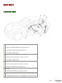
SAFETY
AIR BAG SYSTEM SERVICE CAUTIONS/SERVICE WARNINGS
(w)
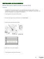
Air Bag Module Inspection
•
Inspecting an air bag module using a tester can operate (deploy) the air bag module, which may cause
serious injury. Do not use a tester to inspect an air bag module. Always use the on-board diagnostic
function to diagnose the air bag module for malfunctions.
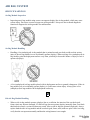
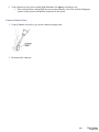
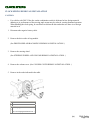
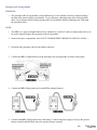
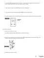
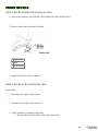
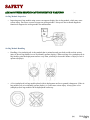
Air Bag Module Handling
•
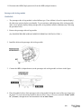
Handling a live (undeployed) air bag module that is pointed toward your body could result in serious
injury if the air bag module were to accidentally operate (deploy). When carrying a live (undeployed) air
bag module, point the deployment surface away from your body to lessen the chance of injury in case it
operates (deploys).
•
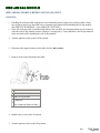
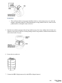
A live (undeployed) air bag module placed with its deployment surface to ground is dangerous. If the air
bag module were to accidentally operate (deploy), it could cause serious injury. Always place a live
(undeployed) air bag module with its deployment surface up.
(w)
RX-8 Safety
Page 1
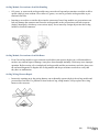
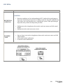
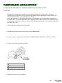
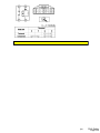
Side Air Bag Module Handling
•
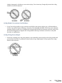
When a side air bag module operates (deploys) due to a collision, the interior of the seat back (pad,
frame, trim) may become damaged. If a side air bag does not operate (deploy) normally from a seat back
that has been reused, a serious accident may result. After a side air bag has operated (deployed), always
replace both the side air bag module and the seat back (pad, frame, trim) with new parts. After servicing,
verify that the seat operates normally and that the wiring harness is not caught.
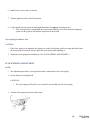
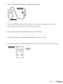
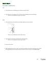
SAS Control Module Handling
•
Removing the SAS control module or disconnecting the SAS control module connector with the ignition
switch at the ON position can activate the sensor in the SAS control module and operate (deploy) the air
bags and pre-tensioner seat belts, which may cause serious injury. Before removing the SAS control
module or disconnecting the SAS control module connector, always turn the ignition switch to the
LOCK position, disconnect the negative battery cable, and then wait for 1 min or more to allow the
backup power supply of the SAS control module to deplete its stored power.
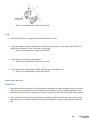
•
Connecting the SAS control module connector with the SAS control module not securely fixed to the
vehicle is dangerous. The sensor in the SAS control module could send an electrical signal to the air bag
modules and pre-tensioner seat belts. This will operate (deploy) the air bags and pre-tensioner seat belts,
which may result in serious injury. Therefore, before connecting the connector, securely fix the SAS
control module to the vehicle.
•
Because a sensor is built into the SAS control module, once the air bags and pre-tensioner seat belts
have operated (deployed) due to a collision or other causes, the SAS control module must be replaced
with a new one even if the used one does not have any visible external damage or deformation. The used
SAS control module may have been damaged internally which may cause improper operation. If the
SAS control module is reused, the air bags and pre-tensioner seat belts may not operate (deploy)
normally, which could result in a serious accident. Always replace the SAS control module with a new
one. The SAS control module cannot be bench-checked or self-checked.
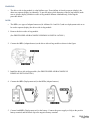
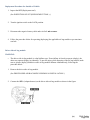
Crash Zone Sensor Handling
•
Removing the crash zone sensor or disconnecting the crash zone sensor connector with the ignition
switch at the ON position can activate the crash zone sensor and operate (deploy) the air bags and pretensioner seat belts, which may cause serious injury. Before removing the crash zone sensor or
disconnecting the crash zone sensor connector, always turn the ignition switch to the LOCK position,
disconnect the negative battery cable, and then wait for 1 min or more to allow the backup power supply
of the SAS control module to deplete its stored power.
•
If the crash zone sensor is subjected to shock or the sensor is disassembled, the air bags and pretensioner seat belts may accidentally operate (deploy) and cause injury, or the system may fail to operate
normally and cause a serious accident. Do not subject the crash zone sensor to shock or disassemble the
sensor.
•
Because a sensor is built into the crash zone sensor, once the air bags and pre-tensioner seat belts have
operated (deployed) due to a collision or other causes, the crash zone sensor must be replaced with a
new one even if the used one does not have any visible external damage or deformation. If the crash
zone sensor is reused, the air bags and pre-tensioner seat belts may not operate (deploy) normally, which
could result in a serious accident. Always replace the crash zone sensor with a new one. The crash zone
sensor cannot be bench-checked or self-checked.
(w)
RX-8 Safety
Page 2
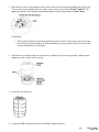
Side Air Bag Sensor Handling
•
Removing the side air bag sensor or disconnecting the side air bag sensor connector with the ignition
switch at the ON position can activate the side air bag sensor and operate (deploy) the side air bag,
which may cause serious injury. Before removing the side air bag sensor or disconnecting the side air
bag sensor connector, always turn the ignition switch to the LOCK position, disconnect the negative
battery cable, and then wait for 1 min or more to allow the backup power supply of the SAS control
module to deplete its stored power.
•
If the side air bag sensor is subjected to shock or the sensor is disassembled, the side air bag may
accidentally operate (deploy) and cause injury, or the system may fail to operate normally and cause a
serious accident. Do not subject the side air bag sensor to shock or disassemble the sensor.
•
Because a sensor is built into the side air bag sensor, once the air bag has operated (deployed) due to a
collision or other causes, the side air bag sensor must be replaced with a new one even if the used one
does not have any visible external damage or deformation. If the side air bag sensor is reused, the side
air bag may not operate (deploy) normally, which could result in a serious accident. Always replace the
side air bag sensor with a new one. The side air bag sensor cannot be bench-checked or self-checked.
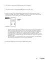
Pre-tensioner Seat Belt Inspection
•
Inspecting a pre-tensioner seat belt using a tester can operate (deploy) the pre-tensioner seat belt, which
may cause serious injury. Do not use a tester to inspect a pre-tensioner seat belt. Always use the onboard diagnostic function to diagnose the pre-tensioner seat belt for malfunctions.
Air Bag System Component Disassembly
•
Disassembling the air bag system components could cause it to not operate (deploy) normally. Never
disassemble any air bag system components.
(w)
RX-8 Safety
Page 3
Air Bag Module, Pre-tensioner Seat Belt Handling
•
Oil, grease, or water on the air bag modules may cause the air bags and pre-tensioner seat belts to fail to
operate (deploy) in an accident. Never allow oil, grease, or water to get on the air bag modules or pretensioner seat belts.
•
Inserting a screwdriver or similar object into the connector of an air bag module or a pre-tensioner seat
belt may damage the connector and cause the air bag module or the pre-tensioner seat belt to operate
(deploy) improperly, which may cause serious injury. Never insert any foreign objects into the air bag
module or seat belt connectors.
Air Bag Module, Pre-tensioner Seat Belt Reuse
•
Even if an air bag module or a pre-tensioner seat belt does not operate (deploy) in a collision and does
not have any external signs of damage, it may have been damaged internally, which may cause improper
operation. Before reusing a live (undeployed) air bag module and the pre-tensioner seat belts, always use
the on-board diagnostic to diagnose the air bag module and the pre-tensioner seat belts to verify that
they have no malfunction.
Air Bag Wiring Harness Repair
•
Incorrectly repairing an air bag wiring harness can accidentally operate (deploy) the air bag module and
pre-tensioner seat belts. If a problem is found in the air bag wiring harness, always replace the wiring
harness with a new one.
(w)
RX-8 Safety
Page 4
(w)
RX-8 Safety
Page 5
(w)
RX-8 Safety
Page 6
(w)
RX-8 Safety
Page 7
(w)
RX-8 Safety
Page 8
(w)
RX-8 Safety
Page 9
(w)
RX-8 Safety
Page 10
FOREWORD
Outline
•
•
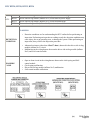
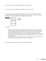
The OBD (on-board diagnostic) system has the following functions:
Malfunction detection function: Detects malfunctions in the air bag system and outputs DTCs.
Data monitor function: Reads out specific input/output signals and the system status.
Diagnostic DTCs can be read/cleared using the WDS or equivalent.
NOTE:
•
When the air bag system is malfunctioning, turn the ignition switch to the ON position to display
the current DTC using the air bag system warning light on the instrument cluster. However this
light is strictly for reference. Make sure to inspect the system using the WDS or equivalent.
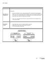
FLOWCHART
•
Use the following flowchart to verify the cause of the trouble.
NOTE:
•
•
While performing the inspection of the past malfunction code, the applicable DTCs may be
added to memory by removing or disconnecting the related parts. Inspect only the DTCs that
were indicated before inspecting.
When DTCs of the present malfunction are no longer output after present or past malfunctions or
both have been repaired, be sure to perform past malfunction display cancellation to prevent
repair of malfunctions that have already been repaired.
(w)
RX-8 Safety
Page 11
(w)
RX-8 Safety
Page 12
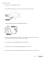
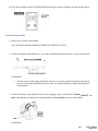
PID/DATA MONITOR DISPLAY
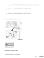
1. Connect the WDS or equivalent to the DLC-2 connector (16-pin).
2. Display the data monitor items.
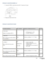
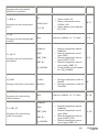
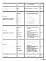
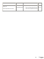
PID/DATA MONITOR TABLE
PID name (definition)
Unit/Condition
Operation Condition (Reference)
Terminal
CCNT_RCM
(Number of continuous DTCs)
•
•
DTCs detected: 1255
No DTCs detected: 0
D_ABAGR2
(Driver-side air bag module (inflator
No.2) resistance)
D_CRSH_S
(Driver-side side air bag sensor
status)
Ohms
OK/
COMM_FAIL/
INT_FAIL
Under any condition: 1.53.7 ohms
•
•
•
Sensor normal: OK
Sensor communication error:
COMM_FAIL
Sensor internal circuit abnormal:
INT_FAIL
1G, 1J
2Z, 2AA
DABAGR
(Driver-side air bag module (inflator
No.1) resistance)
Ohms
Under any condition: 1.53.7 ohms
1S, 1V
D_PTENSFLT
NORMAL/
(Driver-side pre-tensioner seat belt
2P, 2S
•
Related wiring harness normal:
(w)
RX-8 Safety
Page 13
circuit status)
DR_BUKL
(Driver-side buckle switch status)
OPEN/
•
SHRT_GND/
•
SHRT_B+/
•
SQ_LOWRES
•
Buckled/
Unbuckled
•
•
NORMAL
Related wiring harness circuit
open: OPEN
Related wiring harness short to
ground: SHRT_GND
Related wiring harness short to
power supply: SHRT_B+
Pre-tensioner seat belt circuit
resistance low: SQ_LOWRES
Driver-side buckle switch on:
Buckled
Driver-side buckle switch off:
Unbuckled
2T
DR_CURTN
(Driver-side curtain air bag module
resistance)
Ohms
Under any condition: 1.43.2 ohms
2V, 2Y
Ohms
Under any condition: 1.53.1 ohms
2P, 2S
Ohms
Under any condition: 1.43.2 ohms
2M, 2O
DR_PTENS
(Driver-side pre-tensioner seat belt
resistance)
DS_AB
(Driver-side side air bag module
resistance)
NORMAL/
DS_AB_ST
(Driver-side side air bag module
circuit status)
•
OPEN/
•
SHRT_GND/
•
SHRT_B+/
•
SQ_LOWRES
•
Related wiring harness normal:
NORMAL
Related wiring harness circuit
open: OPEN
Related wiring harness short to
ground: SHRT_GND
Related wiring harness short to
power supply: SHRT_B+
Air bag module circuit resistance
low: SQ_LOWRES
2M, 2O
NORMAL/
DS_CURT_ST
OPEN/
(Driver-side curtain air bag module
circuit status)
SHRT_GND/
•
•
•
Related wiring harness normal:
NORMAL
Related wiring harness circuit
open: OPEN
Related wiring harness short to
(w)
2V, 2Y
RX-8 Safety
Page 14
SHRT_B+/
SQ_LOWRES
•
•
NORMAL/
DS1_STAT
(Driver-side air bag module (inflator
No.1) circuit status)
OPEN/
•
SHRT_GND/
•
SHRT_B+/
•
SQ_LOWRES
•
NORMAL/
DS2_STAT
(Driver-side air bag module (inflator
No.2) circuit status)
(Driver-side pre-tensioner seat belt
circuit status)
•
OPEN/
•
SHRT_GND/
•
SHRT_B+/
•
SQ_LOWRES
•
NORMAL/
DSB_P_ST
•
•
OPEN/
•
SHRT_GND/
•
SHRT_B+/
•
SQ_LOWRES
•
ground: SHRT_GND
Related wiring harness short to
power supply: SHRT_B+
Air bag module circuit resistance
low: SQ_LOWRES
Related wiring harness normal:
NORMAL
Related wiring harness circuit
open: OPEN
Related wiring harness short to
ground: SHRT_GND
Related wiring harness short to
power supply: SHRT_B+
Air bag module circuit resistance
low: SQ_LOWRES
Related wiring harness normal:
NORMAL
Related wiring harness circuit
open: OPEN
Related wiring harness short to
ground: SHRT_GND
Related wiring harness short to
power supply: SHRT_B+
Air bag module circuit resistance
low: SQ_LOWRES
Related wiring harness normal:
NORMAL
Related wiring harness circuit
open: OPEN
Related wiring harness short to
ground: SHRT_GND
Related wiring harness short to
power supply: SHRT_B+
Pre-tensioner seat belt circuit
resistance low: SQ_LOWRES
1S, 1V
1G, 1J
2P, 2S
OK/
FNT_CRSH_S
COMM_FAIL/
(Crash zone sensor status)
INT_FAIL
•
•
Sensor normal: OK
Sensor communication error:
COMM_FAIL
(w)
1B, 1C
RX-8 Safety
Page 15
OD_D_CRSH
(Driver-side side air bag sensor
status)
OK/
COMM_FAIL/
INT_FAIL
NORMAL/
OD_D_CURT
(Driver-side curtain air bag module
circuit status)
(Driver-side air bag module (inflator
No.1) circuit status)
(Driver-side air bag module (inflator
No.2) circuit status)
•
•
Sensor normal: OK
Sensor communication error:
COMM_FAIL
Sensor internal circuit abnormal:
INT_FAIL
•
•
•
SHRT_GND/
•
SHRT_B+/
•
SQ_LOWRES
•
•
OPEN/
•
SHRT_GND/
•
SHRT_B+/
•
SQ_LOWRES
•
NORMAL/
OD_DAB2_ST
Sensor internal circuit abnormal:
INT_FAIL
OPEN/
NORMAL/
OD_DAB1_ST
•
•
OPEN/
•
SHRT_GND/
•
SHRT_B+/
•
SQ_LOWRES
•
Related wiring harness normal:
NORMAL
Related wiring harness circuit
open: OPEN
Related wiring harness short to
ground: SHRT_GND
Related wiring harness short to
power supply: SHRT_B+
Air bag module circuit resistance
low: SQ_LOWRES
Related wiring harness normal:
NORMAL
Related wiring harness circuit
open: OPEN
Related wiring harness short to
ground: SHRT_GND
Related wiring harness short to
power supply: SHRT_B+
Air bag module circuit resistance
low: SQ_LOWRES
Related wiring harness normal:
NORMAL
Related wiring harness circuit
open: OPEN
Related wiring harness short to
ground: SHRT_GND
Related wiring harness short to
power supply: SHRT_B+
Air bag module circuit resistance
low: SQ_LOWRES
(w)
2Z, 2AA
2V, 2Y
1S, 1V
1G, 1J
RX-8 Safety
Page 16
NORMAL/
OD_DSAB_ST
(Driver-side side air bag module
circuit status)
OPEN/
•
SHRT_GND/
•
SHRT_B+/
•
SQ_LOWRES
•
OK/
OD_F_CRSH
COMM_FAIL/
(Crash zone sensor status)
INT_FAIL
OD_P_CRSH
(Passenger-side side air bag sensor
status)
OK/
COMM_FAIL/
INT_FAIL
NORMAL/
OD_P_CURT
(Passenger-side curtain air bag
module circuit status)
•
•
•
•
•
•
•
•
OPEN/
•
SHRT_GND/
•
SHRT_B+/
•
SQ_LOWRES
•
Related wiring harness normal:
NORMAL
Related wiring harness circuit
open: OPEN
Related wiring harness short to
ground: SHRT_GND
Related wiring harness short to
power supply: SHRT_B+
Air bag module circuit resistance
low: SQ_LOWRES
Sensor normal: OK
Sensor communication error:
COMM_FAIL
Sensor internal circuit abnormal:
INT_FAIL
Sensor normal: OK
Sensor communication error:
COMM_FAIL
Sensor internal circuit abnormal:
INT_FAIL
Related wiring harness normal:
NORMAL
Related wiring harness circuit
open: OPEN
Related wiring harness short to
ground: SHRT_GND
Related wiring harness short to
power supply: SHRT_B+
Air bag module circuit resistance
low: SQ_LOWRES
2M, 2O
1B, 1C
2B, 2C
2A, 2D
NORMAL/
OD_PAB1_ST
OPEN/
•
(Passenger-side air bag module
(inflator No.1) circuit status)
SHRT_GND/
•
SHRT_B+/
•
Related wiring harness normal:
NORMAL
Related wiring harness circuit
open: OPEN
Related wiring harness short to
ground: SHRT_GND
(w)
1M, 1P
RX-8 Safety
Page 17
SQ_LOWRES
•
•
NORMAL/
OD_PAB2_ST
(Passenger-side air bag module
(inflator No.2) circuit status)
OPEN/
•
SHRT_GND/
•
SHRT_B+/
•
SQ_LOWRES
•
NORMAL/
OD_PSAB_ST
(Passenger-side side air bag module
circuit status)
•
•
OPEN/
•
SHRT_GND/
•
SHRT_B+/
•
SQ_LOWRES
•
Related wiring harness short to
power supply: SHRT_B+
Air bag module circuit resistance
low: SQ_LOWRES
Related wiring harness normal:
NORMAL
Related wiring harness circuit
open: OPEN
Related wiring harness short to
ground: SHRT_GND
Related wiring harness short to
power supply: SHRT_B+
Air bag module circuit resistance
low: SQ_LOWRES
Related wiring harness normal:
NORMAL
Related wiring harness circuit
open: OPEN
Related wiring harness short to
ground: SHRT_GND
Related wiring harness short to
power supply: SHRT_B+
Air bag module circuit resistance
low: SQ_LOWRES
1A, 1D
2I, 2L
P_ABAGR2
(Passenger-side air bag module
(inflator No.2) resistance)
Ohms
NORMAL/
P_PTENSFLT
(Passenger-side pre-tensioner seat
belt circuit status)
PABAGR
Under any condition: 1.42.9 ohms
•
OPEN/
•
SHRT_GND/
•
SHRT_B+/
•
SQ_LOWRES
•
Ohms
Related wiring harness normal:
NORMAL
Related wiring harness circuit
open: OPEN
Related wiring harness short to
ground: SHRT_GND
Related wiring harness short to
power supply: SHRT_B+
Pre-tensioner seat belt circuit
resistance low: SQ_LOWRES
Under any condition: 1.42.9 ohms
(w)
1A, 1D
2G, 2J
1M, 1P
RX-8 Safety
Page 18
(Passenger-side air bag module
(inflator No.1) resistance)
P_CRSH_S
(Passenger-side side air bag sensor
status)
OK/
COMM_FAIL/
INT_FAIL
•
•
•
Sensor normal: OK
Sensor communication error:
COMM_FAIL
Sensor internal circuit abnormal:
INT_FAIL
2B, 2C
PS_AB
(Passenger-side side air bag module
resistance)
Ohms
NORMAL/
PS_AB_ST
(Passenger-side side air bag sensor
circuit status)
PS_BUKL
Under any condition: 1.43.2 ohms
•
OPEN/
•
SHRT_GND/
•
SHRT_B+/
•
SQ_LOWRES
•
Buckled/
(Passenger-side buckle switch status) Unbuckled
•
•
Related wiring harness normal:
NORMAL
Related wiring harness circuit
open: OPEN
Related wiring harness short to
ground: SHRT_GND
Related wiring harness short to
power supply: SHRT_B+
Air bag module circuit resistance
low: SQ_LOWRES
Passenger-side buckle switch on:
Buckled
Passenger-side buckle switch off:
Unbuckled
2I, 2L
2I, 2L
2H
PS_CURTN
(Passenger-side curtain air bag
module resistance)
Ohms
Under any condition: 1.43.2 ohms
2A, 2D
NORMAL/
PS_CURT_ST
(Passenger-side curtain air bag
module circuit status)
OPEN/
SHRT_GND/
SHRT_B+/
SQ_LOWRES
•
•
•
•
Related wiring harness normal:
NORMAL
Related wiring harness circuit
open: OPEN
Related wiring harness short to
ground: SHRT_GND
Related wiring harness short to
power supply: SHRT_B+
(w)
2A, 2D
RX-8 Safety
Page 19
•
Air bag module circuit resistance
low: SQ_LOWRES
PS_PTENS
(Passenger-side pre-tensioner seat
belt resistance)
Ohms
NORMAL/
PS1_STAT
(Passenger-side air bag module
(inflator No.1) circuit status)
(Passenger-side air bag module
(inflator No.2) circuit status)
•
SHRT_GND/
•
SHRT_B+/
•
SQ_LOWRES
•
(Passenger-side pre-tensioner seat
belt circuit status)
•
OPEN/
•
SHRT_GND/
•
SHRT_B+/
•
SQ_LOWRES
•
NORMAL/
PSB_P_ST
•
OPEN/
NORMAL/
PS2_STAT
Under any condition: 1.53.1 ohms
•
OPEN/
•
SHRT_GND/
•
SHRT_B+/
•
SQ_LOWRES
•
Related wiring harness normal:
NORMAL
Related wiring harness circuit
open: OPEN
Related wiring harness short to
ground: SHRT_GND
Related wiring harness short to
power supply: SHRT_B+
Air bag module circuit resistance
low: SQ_LOWRES
Related wiring harness normal:
NORMAL
Related wiring harness circuit
open: OPEN
Related wiring harness short to
ground: SHRT_GND
Related wiring harness short to
power supply: SHRT_B+
Air bag module circuit resistance
low: SQ_LOWRES
Related wiring harness normal:
NORMAL
Related wiring harness circuit
open: OPEN
Related wiring harness short to
ground: SHRT_GND
Related wiring harness short to
power supply: SHRT_B+
Pre-tensioner seat belt circuit
resistance low: SQ_LOWRES
2G, 2J
1M, 1P
1A, 1D
2G, 2J
RCM_VOLT
1W
V
(IG1 voltage)
•
Ignition switch is at ON: B+
(w)
RX-8 Safety
Page 20
•
Other: 0
•
•
Front seat front position: Forward 2W, 2X
Front seat rear position: Rearward
TRAK_SW
Forward/Rearward
(Seat track position sensor state)
(w)
RX-8 Safety
Page 21
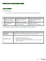
SYMPTOM TROUBLESHOOTING
AIR BAG SYSTEM
Troubleshooting Index
•
Use the chart below verify the symptoms of the trouble in order to diagnose the appropriate area.
No. Troubleshooting item
Description
Page
1
Air bag system warning
light does not illuminate.
Malfunction in air bag system
warning light circuit (short to
ground).
(See NO.1 AIR BAG SYSTEM
WARNING LIGHT DOES NOT
ILLUMINATE )
2
Air bag system warning
light is illuminated
constantly.
(See NO.2 AIR BAG SYSTEM
Malfunction in air bag system
warning light circuit (open circuit or WARNING LIGHT IS
ILLUMINATED CONSTANTLY )
short to power supply).
NO.1 AIR BAG SYSTEM WARNING LIGHT DOES NOT ILLUMINATE
1
DETECTION
CONDITION
POSSIBLE CAUSE
Air bag system warning light does not illuminate.
Malfunction in air bag system warning light circuit (short to ground)
•
•
•
SAS control module malfunction
Instrument cluster (circuit board) malfunction
Short to ground circuit in wiring harness between instrument cluster and
SAS control module
(w)
RX-8 Safety
Page 22
Diagnostic Procedure
•
When performing an asterisked (*) troubleshooting inspection, slightly shake the wiring harness and
connectors while performing the inspection to discover whether poor contact points are the cause of any
intermittent malfunction. If there is a problem, verfy that connectors, terminals and wiring harness are
connected correctly and undamaged.
STEP INSPECTION
INSPECT OTHER WARNING AND INDICATOR
LIGHTS CIRCUIT IN INSTRUMENT CLUSTER
1
•
•
ACTION
Yes
Inspect instrument cluster power supply
Turn the ignition switch to the ON position.
Do other warning and indicator lights illuminate? No system and ground system the, then go
to Step 4.
Replace the SAS control module, then
go to Step 4.
INSPECT SAS CONTROL MODULE
2
Turn the ignition switch to the LOCK
position, then go to the next step.
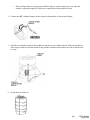
WARNING:
Yes
(See SAS CONTROL MODULE
REMOVAL/INSTALLATION )
(w)
RX-8 Safety
Page 23
•
Handling the air bag system components
improperly can accidentally deploy the air bag
modules and pre-tensioner seat belts, which may
seriously injure you. Read the service warnings
and cautions before handling the air bag system
components.
(See SERVICE WARNINGS .)
(See SERVICE CAUTIONS .)
•
•
•
•
•
•
•
•
•
•
•
•
•
•
•
Turn the ignition switch to LOCK position.
Disconnect the negative battery cable and wait for
1 min or more .
Remove the column cover.
Disconnect the clock spring connector.
No Go to the next step.
Remove the glove compartment.
Disconnect the passenger-side air bag module
connector.
Disconnect the driver and passenger-side side air
bag module connectors.
Disconnect the driver and passenger-side curtain
air bag module connectors.
Remove the rear door lower trim.
Disconnect the driver- and passenger-side pretensioner seat belt connectors.
Partially peel back the floor covering.
Disconnect all SAS control module connectors.
Connect the negative battery cable.
Turn the ignition switch to ON position.
Does the air bag system warning light illuminate?
Replace the wiring harness, then go to
INSPECT WIRING HARNESS BETWEEN SAS
Yes
Step 4.
CONTROL MODULE AND INSTRUMENT CLUSTER
FOR SHORT TO GROUND
*3
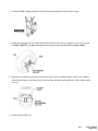
4
•
•
•
•
Turn the ignition switch to LOCK position.
Disconnect the negative battery cable.
Disconnect the instrument cluster connector.
Is there continuity between terminal 2K of the
instrument cluster connector and ground?
CONFIRM THAT MALFUNCTION SYMPTOMS DO
NOT RECUR AFTER REPAIR
Replace the instrument cluster, then go
to next step.
No
(See INSTRUMENT CLUSTER
REMOVAL/INSTALLATION )
Yes
Complete troubleshooting, then explain
repairs to customer.
(w)
RX-8 Safety
Page 24
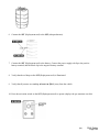
•
•
•
•
Turn the ignition switch to LOCK position.
Disconnect the negative battery cable and wait for
1 min or more .
Connect all SAS control module connectors.
Connect the driver and passenger-side
pre-tensioner seat belt connectors.
•
•
•
•
•
•
•
Connect the driver and passenger-side curtain air
bag module connectors.
Connect the driver and passenger-side side air
bag module connectors.
Connect the passenger-side air bag module
connector.
Connect the clock spring connector.
Connect the negative battery cable.
Turn the ignition switch to ON position.
Does the air bag system warning light operate
properly?
No
Recheck malfunction symptoms, then
repeat from Step 1 if malfunction recurs.
(w)
RX-8 Safety
Page 25
NO.2 AIR BAG SYSTEM WARNING LIGHT IS ILLUMINATED CONSTANTLY
2
DETECTION
CONDITION
POSSIBLE CAUSE
Air bag system warning light is illuminated constantly.
Malfunction in air bag system warning light circuit (open circuit or short to power
supply).
•
•
•
•
•
•
•
•
•
Weak battery
SAS control module malfunction
Instrument cluster (circuit board) malfunction
No connection in SAS control module connector
Poor contact in instrument cluster connector (24-pin)
Open or short to power supply circuit in wiring harness between instrument
cluster and SAS control module
Poor contact at terminals 1T, 1X and/or 1W of SAS control module
connector
Poor contact in wiring harness between terminal 1X of SAS control module
connector and ground
Poor contact in wiring harness between battery and terminal 1W of SAS
control module
(w)
RX-8 Safety
Page 26
Diagnostic Procedure
•
When performing an asterisked (*) troubleshooting inspection, slightly shake the wiring harness and
connectors while performing the inspection to discover whether poor contact points are the cause of any
intermittent malfunction. If there is a problem, verify that connectors, terminals and wiring harness are
connected correctly and undamaged.
STEP INSPECTION
ACTION
Yes Go to the next step.
INSPECT BATTERY
1
•
•
Measure the voltage of battery.
Is the voltage 9 V or more ?
Battery is weak.
No
Inspect charge/discharge system, then
go to Step 9.
(See BATTERY INSPECTION )
VERIFY THAT SAS CONTROL MODULE
CONNECTOR IS CONNECTED
Yes Go to the next step.
WARNING:
•
2
Handling the air bag system components
improperly can accidentally deploy the air bag
modules and pre-tensioner seat belts, which may
seriously injure you. Read the service warnings and
cautions before handling the air bag system
components.
(See SERVICE WARNINGS .)
No
Reconnect the connector properly,
then go to Step 9.
(See SERVICE CAUTIONS .)
•
•
•
•
*3
Turn the ignition switch to LOCK position.
Disconnect the negative battery cable and wait for
1 min or more .
Turn up the floor covering.
Are all SAS control module connectors securely
connected?
Yes Go to the next step.
(w)
RX-8 Safety
Page 27
INSPECT WIRING HARNESS BETWEEN SAS
CONTROL MODULE AND INSTRUMENT CLUSTER
FOR CONTINUITY
•
•
•
•
•
•
•
•
•
•
•
•
Remove the column cover.
Disconnect the clock spring connector.
Remove the glove compartment.
Disconnect the passenger-side air bag module
connector.
Disconnect the driver and passenger-side side air
bag module connectors.
Disconnect the driver and passenger-side curtain
air bag module connectors.
Remove the rear door lower trims.
Disconnect the driver- and passenger-side pretensioner seat belt connectors.
Partially peel back the floor covering.
Disconnect all SAS control module connectors.
Disconnect the instrument cluster connector.
Is there continuity between SAS control module
connector terminal 1T and instrument cluster
connector terminal 2K?
INSPECT WIRING HARNESS BETWEEN SAS
CONTROL MODULE AND INSTRUMENT CLUSTER
FOR SHORT TO POWER SUPPLY
*4
Yes
Replace the wiring harness, then go to
Step 9.
Connect the negative battery cable.
•
•
Turn the ignition switch to ON position.
No Go to the next step.
Measure the voltage at instrument cluster connector
terminal 2K.
Is the voltage 9 V or more ?
CHECK TO SEE WHETHER MALFUNCTION IS IN
AIR BAG SYSTEM WARNING LIGHT IN
INSTRUMENT CLUSTER
•
•
6
Replace the wiring harness, then go to
Step 9.
•
•
5
No
Connect instrument cluster connector terminal 2K
to ground, then reconnect the connector
Does the air bag system warning light illuminate
with ignition switch ON?
Replace the instrument cluster, then
go to Step 9.
Yes
(See INSTRUMENT CLUSTER
REMOVAL/INSTALLATION )
No Go to the next step.
Yes Go to the Step 8.
(w)
RX-8 Safety
Page 28
INSPECT POWER SUPPLY CIRCUIT OF SAS
CONTROL MODULE (TERMINAL 1W)
•
•
•
•
Turn the ignition switch to LOCK position.
Disconnect the negative battery cable and wait for
1 min or more .
Connect all SAS control module connectors.
Connect the driver and passenger-side
pre-tensioner seat belt connectors.
Connect the driver and passenger-side curtain air
bag module connectors.
Connect the driver and passenger-side side air bag
module connectors.
Connect the passenger-side air bag module
connector.
Connect the clock spring connector.
Inspect the voltage for PID/DATA monitor
RCM_VOLT item using WDS or equivalent.
Is the voltage of at least one terminal 9 V or more
?
No Go to the next step.
INSPECT WIRING HARNESS BETWEEN BATTERY
AND FUSE BLOCK
Yes Go to the next step.
•
•
•
•
•
•
7
•
•
•
•
8
Connect the negative battery cable.
Turn the ignition switch to ON position.
Repair the wiring harnesses, then go
Measure the voltage at instrument cluster connector No to Step 9.
terminal 1G.
Is the voltage 9 V or more ?
VERIFY THAT SAS CONTROL MODULE
CONNECTOR TERMINAL 1X IS GROUND
•
Turn the ignition switch to LOCK position.
Replace the SAS control module, then
go to the next step.
Yes
(See SAS CONTROL MODULE
REMOVAL/INSTALLATION )
(w)
RX-8 Safety
Page 29
•
•
•
•
•
•
•
•
•
•
•
•
•
Disconnect the negative battery cable and wait for
1 min or more .
Remove the column cover.
Disconnect the clock spring connector.
Remove the glove compartment.
Disconnect the passenger-side air bag module
connector.
Disconnect the driver and passenger-side side air
bag module connectors.
Disconnect the driver and passenger-side curtain
air bag module connectors.
Remove the rear door lower trims.
Disconnect the driver and passenger-side pretensioner seat belt connectors.
Partially peel back the floor covering.
Disconnect all SAS control module control model
connectors.
Inspect the wiring harness between SAS control
module connector terminal 1X and ground for the
following:
Short to power supply
Open circuit
Is the wiring harness okay?
CONFIRM THAT MALFUNCTION SYMPTOMS DO
NOT RECUR AFTER REPAIR
•
•
•
•
No
Replace the wiring harnesses, then go
to the next step.
Yes
Complete troubleshooting, then
explain repairs to customer.
Turn the ignition switch to LOCK position.
Disconnect the negative battery cable and wait for
1 min or more .
Connect all SAS control module connectors.
Connect the driver and passenger-side
pre-tensioner seat belt connectors.
9
•
•
•
•
•
•
•
•
Connect the driver and passenger-side curtain air
bag module connectors.
Connect the driver and passenger-side side air bag
module connectors.
Connect the passenger-side air bag module
connector.
Connect the clock spring connector.
Connect the instrument cluster connector.
Connect the negative battery cable.
Turn the ignition switch to ON position.
Does the air bag system warning light operate
properly?
Recheck malfunction symptoms, then
No repeat from Step 1 if malfunction
recurs.
(w)
RX-8 Safety
Page 30
DTC B1231
DTC B1231
SAS control module activation (deployment) control freeze
WARNING:
DETECTION
CONDITION
•
Detection conditions are for understanding the DTC outline before performing an
inspection. Performing an inspection with only detection conditions may cause
injury due to an operating error, or damage the system. When performing an
inspection, always follow the inspection procedure.
•
SAS control module determined collision
Diagnostic procedure
ACTION
Replace the SAS control module.
(See SAS CONTROL MODULE REMOVAL/INSTALLATION .)
(w)
RX-8 Safety
Page 31
DTC B1342
•
•
DTC B1342
SAS control module (air bag system warning light DTC 12 is displayed.)
SAS control module DTC 12 detection circuit malfunction (the air bag system
warning light illuminates continuously.)
WARNING:
DETECTION
CONDITION
POSSIBLE
CAUSE
•
Detection conditions are for understanding the DTC outline before performing an
inspection. Performing an inspection with only detection conditions may cause
injury due to an operating error, or damage the system. When performing an
inspection, always follow the inspection procedure.
•
Malfunction in the SAS control module internal circuit
•
SAS control module malfunction
Diagnostic procedure
ACTION
•
Replace the SAS control module.
(See SAS CONTROL MODULE REMOVAL/INSTALLATION )
(w)
RX-8 Safety
Page 32
DTC B1426, B1427
DTC
B 1426
Seat belt warning light circuit short to power supply
B1427
Seat belt warning light circuit open
WARNING:
DETECTION
CONDITION
POSSIBLE
CAUSE
•
Detection conditions are for understanding the DTC outline before performing an
inspection. Performing an inspection according to only the detection conditions may
cause injury due to an operating error, or damage the system. When performing an
inspection, always follow the inspection procedure.
•
Malfunction in the seat belt warning light circuit
•
•
Instrument cluster malfunction
Malfunction of the connectors between the instrument cluster and SAS control
module
Open or short circuit in the wiring harness between the battery and the instrument
cluster
Open or short circuit in the wiring harness between the instrument cluster and SAS
control module
SAS control module malfunction
•
•
•
(w)
RX-8 Safety
Page 33
Diagnostic procedure
STEP INSPECTION
INSPECT FOR CONTINUITY BETWEEN BATTERY
FUSE AND INSTRUMENT CLUSTER
1
•
•
•
•
2
ACTION
Yes Go to next step.
Connect negative battery cable.
Turn the ignition switch to the ON position.
Measure the voltage at instrument cluster connector No Repair the related wiring harness.
terminal 2A.
Is the voltage 9 V or more ?
Yes Go to next step.
Notes:
(w)
RX-8 Safety
Page 34
INSPECT WIRING HARNESS BETWEEN
INSTRUMENT CLUSTER AND SAS CONTROL
MODULE
WARNING:
•
Handling the air bag system components improperly
can accidentally deploy the air bag modules and
pre-tensioner seat belts, which may seriously injure
you. Read the service warnings and cautions before
handling the air bag system components.
(See SERVICE WARNINGS .)
(See SERVICE CAUTIONS .)
•
•
•
•
•
•
•
•
•
•
•
•
•
•
•
Turn the ignition switch to the LOCK position.
Disconnect the negative battery cable and wait for 1
min or more .
Remove the column cover.
Disconnect the clock spring connector.
No Replace the air bag wiring harness.
Remove the glove compartment.
Disconnect the passenger-side air bag module
connector.
Disconnect the driver and passenger-side curtain air
bag module connectors.
Disconnect the driver and passenger-side side air
bag module connectors.
Remove the rear door lower trim.
Disconnect the driver and passenger-side pretensioner seat belt connectors.
Partially peel back the floor covering.
Disconnect the SAS control module connector.
Disconnect the instrument cluster connector.
Inspect the wiring harness between SAS control
module terminal 1E and instrument cluster terminal
2A for the following:
Short to ground
Short to power supply
Open circuit
Is the wiring harness normal?
(w)
RX-8 Safety
Page 35
[Present malfunction
diagnosis]
•
INSPECT SEAT BELT WARNING LIGHT
3
•
•
•
•
Connect the instrument cluster connector.
Ground instrument cluster connector terminal 2G
using a jumper wire.
Turn the ignition switch to the ON position.
Does the seat belt warning light illuminate?
Replace the SAS control
module.
(See SAS CONTROL
MODULE
REMOVAL/INSTALLATIO
N .)
Yes
[Past malfunction diagnosis]
•
DTC troubleshooting
completed.
Replace the instrument cluster.
No
(See INSTRUMENT CLUSTER
REMOVAL/INSTALLATION .)
(w)
RX-8 Safety
Page 36
DTC B1869, B1870
B1869
DTC
•
•
B1870
Air bag system warning light circuit open (the air bag system warning light is
continuously illuminated.)
Air bag system warning light circuit short to body ground (the air bag system
warning light is never illuminated.)
Air bag system warning light system circuit short to power supply (the air bag system
warning light is continuously illuminated.)
WARNING:
DETECTION
CONDITION
POSSIBLE
CAUSE
•
Detection conditions are for understanding the DTC outline before performing an
inspection. Performing an inspection according to only the detection conditions may
cause injury due to an operating error, or damage the system. When performing an
inspection, always follow the inspection procedure.
•
Malfunction in the air bag system warning light circuit
•
•
Instrument cluster malfunction
Malfunction of the connectors between the instrument cluster and SAS control
module
Open or short circuit in the wiring harness between the battery and the instrument
cluster
Open or short circuit in the wiring harness between the instrument cluster and SAS
control module
SAS control module malfunction
•
•
•
(w)
RX-8 Safety
Page 37
Diagnostic procedure
STEP INSPECTION
INSPECT FOR CONTINUITY BETWEEN BATTERY
FUSE AND INSTRUMENT CLUSTER
1
•
•
•
2
ACTION
Yes Go to next step.
Turn the ignition switch to the ON position.
Measure the voltage at instrument cluster connector No Repair the related wiring harness.
terminal 2K.
Is the voltage 9 V or more ?
Yes Go to next step.
(w)
RX-8 Safety
Page 38
INSPECT WIRING HARNESS BETWEEN
INSTRUMENT CLUSTER AND SAS CONTROL
MODULE
WARNING:
•
Handling the air bag system components improperly
can accidentally deploy the air bag modules and
pre-tensioner seat belts, which may seriously injure
you. Read the service warnings and cautions before
handling the air bag system components.
(See SERVICE WARNINGS .)
(See SERVICE CAUTIONS .)
•
•
•
•
•
•
•
•
•
•
•
•
•
•
•
Turn the ignition switch to the LOCK position.
Disconnect the negative battery cable and wait for 1
min or more .
Remove the column cover.
Disconnect the clock spring connector.
No Replace the air bag wiring harness.
Remove the glove compartment.
Disconnect the passenger-side air bag module
connector.
Disconnect the driver and passenger-side curtain air
bag module connectors.
Disconnect the driver and passenger-side side air
bag module connectors.
Remove the rear door lower trim.
Disconnect the driver and passenger-side pretensioner seat belt connectors.
Partially peel back the floor covering.
Disconnect the SAS control module connector.
Disconnect the instrument cluster connector.
Inspect the wiring harness between SAS control
module terminal 1T and instrument cluster terminal
2K for the following:
Short to ground
Short to power supply
Open circuit
Is the wiring harness normal?
INSPECT AIR BAG SYSTEM WARNING LIGHT
4
•
•
•
Connect the instrument cluster connector.
Turn the ignition switch to the ON position.
Does the air bag system warning light illuminate?
Yes Go to next step.
Replace the instrument cluster.
No
(See INSTRUMENT CLUSTER
REMOVAL/INSTALLATION )
(w)
RX-8 Safety
Page 39
[Present malfunction
diagnosis]
•
INSPECT AIR BAG SYSTEM WARNING LIGHT
5
•
•
Replace the SAS control
module.
(See SAS CONTROL
MODULE
REMOVAL/INSTALLATIO
N .)
Yes
Ground instrument cluster connector terminal 2K to
the body using a jumper wire.
Does the air bag system warning light go out?
[Past malfunction diagnosis]
•
DTC troubleshooting
completed.
Replace the instrument cluster.
No
(See INSTRUMENT CLUSTER
REMOVAL/INSTALLATION )
(w)
RX-8 Safety
Page 40
DTC B1877, B1878, B1879, B1885
DTC
B1877
Driver-side pre-tensioner seat belt circuit resistance high
B1878
Driver-side pre-tensioner seat belt circuit short to power supply
B1879
Driver-side pre-tensioner seat belt circuit short to ground
B1885
Driver-side pre-tensioner seat belt circuit resistance low
WARNING:
•
Detection conditions are for understanding the DTC outline before performing an
inspection. Performing an inspection according to only the detection conditions may
cause injury due to an operating error, or damage the system. When performing an
inspection, always follow the inspection procedure.
•
Abnormal resistance (other than 1.5
3.1 ohms ) detected in the driver-side pretensioner seat belt circuit
Malfunction in the wiring harness between the driver-side pre-tensioner seat belt
and SAS control module
DETECTION
CONDITION
•
POSSIBLE
CAUSE
•
•
•
Open or short circuit in the wiring harness between the driver-side pre-tensioner seat
belt and SAS control module
Driver-side pre-tensioner seat belt malfunction
SAS control module malfunction
(w)
RX-8 Safety
Page 41
Diagnostic procedure
STEP INSPECTION
ACTION
[Present malfunction
diagnosis]
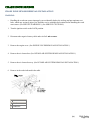
INSPECT DRIVER-SIDE PRE-TENSIONER SEAT BELT
•
Using the WDS or equivalent, verify the following
PID/DATA monitor.
(See PID/DATA MONITOR TABLE .)
1
•
(See SAS CONTROL
MODULE
REMOVAL/INSTALLATIO
N .)
Yes
DR_PTENS
Is driver-side pre-tensioner seat belt resistance
normal?
Resistance: 1.5
3.1 ohms
•
Replace the SAS control
module.
[Past malfunction
diagnosis]
•
DTC troubleshooting
completed.
No Go to next step.
INSPECT DRIVER-SIDE PRE-TENSIONER SEAT BELT Yes Replace the air bag wiring harness.
CONNECTOR
WARNING:
•
Handling the air bag system components improperly
can accidentally deploy the air bag modules and pretensioner seat belts, which may seriously injure you.
Read the service warnings and cautions before
handling the air bag system components.
(See SERVICE WARNINGS .)
2
(See SERVICE CAUTIONS .)
•
•
•
•
•
No Go to next step.
Turn the ignition switch to the LOCK position.
Disconnect the negative battery cable and wait for 1
min or more .
Remove the driver-side rear door lower trim.
Disconnect the driver-side pre-tensioner seat belt
connector.
Is there any malfunction of the driver-side pretensioner seat belt connector?
(w)
RX-8 Safety
Page 42
VERIFY WHETHER MALFUNCTION IS IN DRIVERSIDE PRE-TENSIONER SEAT BELT OR RELATED
WIRING HARNESS
•
•
3
•
•
•
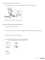
Replace the driver-side pre-tensioner
seat belt.
Yes
(See FRONT SEAT BELT
Connect the leads of the SST (Fuel and thermometer
REMOVAL/INSTALLATION .)
checker) or apply 2-ohm resistance to driver-side
pre-tensioner seat belt connector terminals A and B.
Set the resistance of the SST (Fuel and thermometer
checker) to the 2-ohm position.
Connect the negative battery cable.
Turn the ignition switch to the ON position.
Using the WDS or equivalent, verify the following
Replace the air bag wiring harness,
No
PID/DATA monitor.
then go to the next step.
(See PID/DATA MONITOR TABLE .)
DSB_P_ST
Are related wiring harnesses normal?
•
[Present malfunction
diagnosis]
•
INSPECT SAS CONTROL MODULE
•
•
4
•
•
Turn the ignition switch to the LOCK position.
Disconnect the negative battery cable and wait for 1
min or more .
Connect the driver-side pre-tensioner seat belt
connector.
Are DTCs B1877, B1878, B1879 and/or B1885
indicated?
Replace the SAS control
module.
(See SAS CONTROL
MODULE
REMOVAL/INSTALLATIO
N .)
Yes
[Past malfunction
diagnosis]
•
DTC troubleshooting
completed.
No DTC troubleshooting completed.
(w)
RX-8 Safety
Page 43
DTC B1881, B1882, B1883, B1886
DTC
B1881
Passenger-side pre-tensioner seat belt circuit resistance high
B1882
Passenger-side pre-tensioner seat belt circuit short to power supply
B1883
Passenger-side pre-tensioner seat belt circuit short to body ground
B1886
Passenger-side pre-tensioner seat belt circuit resistance low
WARNING:
•
Detection conditions are for understanding the DTC outline before performing an
inspection. Performing an inspection according to only the detection conditions may
cause injury due to an operating error, or damage the system. When performing an
inspection, always follow the inspection procedure.
•
Abnormal resistance (other than 1.5
3.1 ohms ) detected in the passenger-side pretensioner seat belt circuit
Malfunction in the wiring harness between the passenger-side pre-tensioner seat belt
and SAS control module
DETECTION
CONDITION
•
POSSIBLE
CAUSE
•
•
•
Open or short circuit in the wiring harness between the passenger-side pre-tensioner
seat belt and SAS control module
Passenger-side pre-tensioner seat belt malfunction
SAS control module malfunction
(w)
RX-8 Safety
Page 44
Diagnostic procedure
STEP INSPECTION
ACTION
[Present malfunction diagnosis]
INSPECT PASSENGER-SIDE PRE-TENSIONER
SEAT BELT
•
Using the WDS or equivalent, verify the following
PID/DATA monitor.
(See PID/DATA MONITOR TABLE .)
1
•
(See SAS CONTROL MODULE
Yes REMOVAL/INSTALLATION .)
[Past malfunction diagnosis]
PS_PTENS
Is the resistance of the passenger-side pre-tensioner
seat belt normal?
Resistance: 1.5
3.1 ohms
•
Replace the SAS control
module.
•
DTC troubleshooting
completed.
No Go to the next step.
INSPECT PASSENGER-SIDE PRE-TENSIONER
SEAT BELT CONNECTOR
Yes Replace the air bag wiring harness.
WARNING:
•
Handling the air bag system components improperly
can accidentally deploy the air bag modules and pretensioner seat belts, which may seriously injure you.
Read the service warnings and cautions before
handling the air bag system components.
(See SERVICE WARNINGS .)
2
(See SERVICE CAUTIONS .)
•
•
•
•
•
3
No Go to the next step.
Turn the ignition switch to the LOCK position.
Disconnect the negative battery cable and wait for 1
min or more .
Remove the passenger-side rear door lower trim.
Disconnect the passenger-side pre-tensioner seat belt
connector.
Is there any malfunction of the passenger-side pretensioner seat belt connector?
VERIFY WHETHER MALFUNCTION IS IN
PASSENGER-SIDE PRE-TENSIONER SEAT BELT
OR RELATED WIRING HARNESS
Replace the passenger-side pretensioner seat belt.
Yes
(See FRONT SEAT BELT
REMOVAL/INSTALLATION .)
(w)
RX-8 Safety
Page 45
•
•
•
•
•
Connect the leads of the SST (Fuel and thermometer
checker) or apply 2-ohm resistance to passenger-side
pre-tensioner seat belt connector terminals A and B.
Set the resistance of the SST (Fuel and thermometer
checker) to the 2-ohm position.
Connect the negative battery cable.
Turn the ignition switch to the ON position.
Replace the air bag wiring harness,
No
Using the WDS or equivalent, verify the following
then go to the next step.
PID/DATA monitor.
(See PID/DATA MONITOR TABLE .)
PSB_P_ST
Are related wiring harnesses normal?
•
[Present malfunction diagnosis]
•
INSPECT SAS CONTROL MODULE
•
•
4
•
•
Turn the ignition switch to the LOCK position.
Disconnect the negative battery cable and wait for 1
min or more .
Connect the passenger-side pre-tensioner seat belt
connector.
Are DTCs B1881, B1882, B1883 and/or B1886
indicated?
Replace the SAS control
module.
(See SAS CONTROL
MODULE
REMOVAL/INSTALLATIO
N .)
Yes
[Past malfunction diagnosis]
•
DTC troubleshooting
completed.
No DTC troubleshooting completed.
(w)
RX-8 Safety
Page 46
DTC B1913, B1916, B1932, B1934
DTC
B1913
Driver-side air bag module (inflator No.1) circuit short to body ground
B1916
Driver-side air bag module (inflator No.1) circuit short to power supply
B1932
Driver-side air bag module (inflator No.1) circuit resistance high
B1934
Driver-side air bag module (inflator No.1) circuit resistance low
WARNING:
•
Detection conditions are for understanding the DTC outline before performing an
inspection. Performing an inspection according to only the detection conditions may
cause injury due to an operating error, or damage the system. When performing an
inspection, always follow the inspection procedure.
•
Abnormal resistance (other than 1.5
3.7 ohms ) detected in the driver-side air bag
module (inflator No.1) circuit
Malfunction in the wiring harness between the driver-side air bag module (inflator
No.1) and SAS control module
DETECTION
CONDITION
•
POSSIBLE
CAUSE
•
•
•
•
Open or short circuit in the wiring harness between the clock spring and SAS
control module
Clock spring malfunction
Driver-side air bag module (inflator No.1) malfunction
SAS control module malfunction
(w)
RX-8 Safety
Page 47
Diagnostic procedure
STEP INSPECTION
ACTION
[Present malfunction diagnosis]
•
INSPECT DRIVER-SIDE AIR BAG MODULE
(INFLATOR NO.1)
•
1
•
Using the WDS or equivalent, verify the following
PID/DATA monitor. (See PID/DATA MONITOR
TABLE .)
DABAGR
Is the resistance of the driver-side air bag module
normal?
Resistance: 1.5
3.7 ohms
Replace the SAS control
module.
(See SAS CONTROL
MODULE
REMOVAL/INSTALLATIO
N .)
Yes
[Past malfunction diagnosis]
•
DTC troubleshooting
completed.
No Go to the next step.
INSPECT DRIVER-SIDE AIR BAG MODULE
CONNECTOR (CLOCK SPRING)
Yes Replace the air bag wiring harness.
WARNING:
•
2
Handling the air bag system components improperly
can accidentally deploy the air bag modules and pretensioner seat belts, which may seriously injure you.
Read the service warnings and cautions before
handling the air bag system components.
(See SERVICE WARNINGS .)
No Go to the next step.
(See SERVICE CAUTIONS .)
•
•
•
•
3
Turn the ignition switch to the LOCK position.
Disconnect the negative battery cable and wait for 1
min or more .
Remove the driver-side air bag module.
Is there any malfunction of the driver-side air bag
module connector?
VERIFY WHETHER MALFUNCTION IS IN
DRIVER-SIDE AIR BAG MODULE (INFLATOR
NO.1) OR RELATED WIRING HARNESS
•
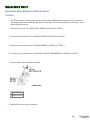
Connect the leads of the SST (Fuel and thermometer
checker) or apply 2 ohm resistance to driver side air
Replace the driver-side air bag
module.
Yes
(See DRIVER-SIDE AIR BAG
MODULE
REMOVAL/INSTALLATION .)
(w)
RX-8 Safety
Page 48
•
•
•
•
checker) or apply 2-ohm resistance to driver-side air
bag module (inflator No.1) connector terminals 3A
and 3B, and driver-side air bag module (inflator
No.2) connector terminals 4A and 4B.
Set the resistance of the SST (Fuel and thermometer
checker) to the 2-ohm position.
Connect the negative battery cable.
Turn the ignition switch to the ON position.
Using the WDS or equivalent, verify the following
PID/DATA monitor.
No Go to the next step.
(See PID/DATA MONITOR TABLE .)
OD_DAB1_ST
Are related wiring harnesses normal?
•
INSPECT CLOCK SPRING
•
4
Inspect the clock spring.
(See CLOCK SPRING INSPECTION .)
•
Is the clock spring normal?
INSPECT WIRING HARNESS BETWEEN CLOCK
SPRING AND SAS CONTROL MODULE
•
•
5
•
•
•
•
•
Yes Go to the next step.
Replace the clock spring.
No
(See CLOCK SPRING
REMOVAL/INSTALLATION .)
[Present malfunction diagnosis]
• Replace the SAS control
module.
Turn the ignition switch to the LOCK position.
Disconnect the negative battery cable and wait for 1
min or more .
(See SAS CONTROL MODULE
Remove the column cover.
Yes REMOVAL/INSTALLATION .)
Disconnect the clock spring connector.
Remove the glove compartment.
[Past malfunction diagnosis]
Disconnect the passenger-side air bag module
connector.
• DTC troubleshooting
Disconnect the driver and passenger-side side air bag
completed.
module connectors.
(w)
RX-8 Safety
Page 49
•
•
•
•
•
•
Disconnect the driver and passenger-side curtain air
bag module connectors.
Remove the rear door lower trim.
Disconnect the driver and passenger-side pretensioner seat belt connectors.
Partially peel back the floor covering.
Inspect the wiring harness between SAS control
module terminal 1S and clock spring terminal 1D,
SAS control module terminal 1V and clock spring
terminal 1C for the following:
Short to ground
Short to power supply
Open circuit
Is the wiring harness normal?
No Replace the air bag wiring harness.
Notes:
(w)
RX-8 Safety
Page 50
DTC B1913, B1925, B1933, B1935
DTC
B1913
Passenger-side air bag module (inflator No.1) circuit short to body ground
B1925
Passenger-side air bag module (inflator No.1) circuit short to power supply
B1933
Passenger-side air bag module (inflator No.1) circuit resistance high
B1935
Passenger-side air bag module (inflator No.1) circuit resistance low
WARNING:
•
Detection conditions are for understanding the DTC outline before performing an
inspection. Performing an inspection according to only the detection conditions may
cause injury due to an operating error, or damage the system. When performing an
inspection, always follow the inspection procedure.
•
Abnormal resistance (other than 1.4
2.9 ohms ) detected in the passenger-side
driver-side air bag module (inflator No.1) circuit
Malfunction in the wiring harness between the passenger-side air bag module
(inflator No.1) and SAS control module
DETECTION
CONDITION
•
POSSIBLE
CAUSE
•
•
•
Open or short circuit in the wiring harness between the passenger-side air bag
module (inflator No.1) and SAS control module
Passenger-side air bag module (inflator No.1) malfunction
SAS control module malfunction
(w)
RX-8 Safety
Page 51
Diagnostic procedure
STEP INSPECTION
ACTION
[Present malfunction diagnosis]
INSPECT PASSENGER-SIDE AIR BAG MODULE
(INFLATOR NO.1)
•
Using the WDS or equivalent, verify the following
PID/DATA monitor.
(See PID/DATA MONITOR TABLE .)
1
•
•
PABAGR
Is the resistance of the passenger-side air bag
module normal?
Resistance: 1.4
2.9 ohms
Replace the SAS control
module.
(See SAS CONTROL
MODULE
REMOVAL/INSTALLATIO
N .)
Yes
[Past malfunction diagnosis]
•
DTC troubleshooting
completed.
No Go to the next step.
INSPECT PASSENGER-SIDE AIR BAG MODULE
(INFLATOR NO.1) CONNECTOR
Yes Replace the air bag wiring harness.
WARNING:
•
Handling the air bag system components improperly
can accidentally deploy the air bag modules and pretensioner seat belts, which may seriously injure you.
Read the service warnings and cautions before
handling the air bag system components.
(See SERVICE WARNINGS .)
2
(See SERVICE CAUTIONS .)
•
•
•
•
•
No Go to the next step.
Turn the ignition switch to the LOCK position.
Disconnect the negative battery cable and wait for 1
min or more .
Remove the glove compartment.
Disconnect the passenger-side air bag module
connector.
Is there any malfunction of the passenger-side air
bag module connector?
(w)
RX-8 Safety
Page 52
VERIFY WHETHER MALFUNCTION IS IN
PASSENGER-SIDE AIR BAG MODULE (INFLATOR
NO.1) OR RELATED WIRING HARNESS
•
3
•
•
•
•
Replace the passenger-side air bag
module.
Yes
(See PASSENGER-SIDE AIR BAG
Connect the leads of the SST (Fuel and thermometer
MODULE
checker) or apply 2-ohm resistance to passengerREMOVAL/INSTALLATION .)
side air bag module (inflator No.1) connector
terminals A and B, and passenger-side air bag
module (inflator No.2) connector terminals A and B.
Set the resistance of the SST (Fuel and thermometer
checker) to the 2-ohm position.
Connect the negative battery cable.
Turn the ignition switch to the ON position.
Using the WDS or equivalent, verify the following No Replace the air bag wiring harness,
then go to the next step.
PID/DATA monitor.
(See PID/DATA MONITOR TABLE .)
•
OD_PAB1ST
Are related wiring harnesses normal?
[Present malfunction diagnosis]
•
INSPECT SAS CONTROL MODULE
•
•
4
•
•
Replace the SAS control
module.
(See SAS CONTROL
Turn the ignition switch to the LOCK position.
MODULE
Disconnect the negative battery cable and wait for 1
REMOVAL/INSTALLATIO
Yes
min or more .
N .)
Connect the passenger-side air bag module
connector.
[Past malfunction diagnosis]
Are DTCs B1913, B1925, B1933 and/or B1935
indicated?
• DTC troubleshooting
completed.
No DTC troubleshooting completed.
(w)
RX-8 Safety
Page 53
Diagnostic procedure
STEP INSPECTION
ACTION
[Present malfunction diagnosis]
•
Replace the SAS control module.
INSPECT SAS CONTROL MODULE
1
•
•
(See SAS CONTROL MODULE
REMOVAL/INSTALLATION .)
Using the WDS or equivalent, perform Yes
SAS control module configuration.
[Past malfunction diagnosis]
Is DTC B1921 indicated?
•
DTC troubleshooting completed.
No DTC troubleshooting completed.
(w)
RX-8 Safety
Page 54
DTC B1992, B1993, B1994, B1995
DTC
B1992
Driver-side side air bag module circuit short to power supply
B1993
Driver-side side air bag module circuit short to body ground
B1994
Driver-side side air bag module circuit resistance high
B1995
Driver-side side air bag module circuit resistance low
WARNING:
•
Detection conditions are for understanding the DTC outline before performing an
inspection. Performing an inspection according to only the detection conditions may
cause injury due to an operating error, or damage the system. When performing an
inspection, always follow the inspection procedure.
•
Abnormal resistance (other than 1.4
3.2 ohms ) detected in the driver-side side air
bag module circuit
Malfunction in the wiring harness between the driver-side side air bag module and
SAS control module
DETECTION
CONDITION
•
POSSIBLE
CAUSE
•
•
•
Open or short circuit in the wiring harness between the driver-side side air bag
module and SAS control module
Driver-side side air bag module malfunction
SAS control module malfunction
(w)
RX-8 Safety
Page 55
Diagnostic procedure
STEP INSPECTION
ACTION
[Present malfunction diagnosis]
INSPECT DRIVER-SIDE SIDE AIR BAG MODULE
•
Using the WDS or equivalent, verify the following
PID/DATA monitor.
(See PID/DATA MONITOR TABLE .)
1
•
•
(See SAS CONTROL
MODULE
REMOVAL/INSTALLATIO
N .)
Yes
DS_AB
Is the resistance of the driver-side side air bag
module normal?
Resistance: 1.4
3.2 ohms
Replace the SAS control
module.
[Past malfunction diagnosis]
•
DTC troubleshooting
completed.
No Go to the next step.
INSPECT DRIVER-SIDE SIDE AIR BAG MODULE
CONNECTOR
Yes Replace the air bag wiring harness.
WARNING:
•
2
Handling the air bag system components improperly
can accidentally deploy the air bag modules and pretensioner seat belts, which may seriously injure you.
Read the service warnings and cautions before
handling the air bag system components.
(See SERVICE WARNINGS .)
No Go to the next step.
(See SERVICE CAUTIONS .)
•
•
•
•
3
Turn the ignition switch to the LOCK position.
Disconnect the negative battery cable and wait for 1
min or more .
Disconnect the driver-side side air bag module
connector.
Is there any malfunction of the driver-side side air
bag module connector?
VERIFY WHETHER MALFUNCTION IS IN
DRIVER-SIDE SIDE AIR BAG MODULE OR
RELATED WIRING HARNESS
Replace the driver-side side air bag
module.
Yes
(See SIDE AIR BAG MODULE
REMOVAL/INSTALLATION .)
(w)
RX-8 Safety
Page 56
•
•
•
•
•
•
•
Connect the leads of the SST (Fuel and thermometer
checker) or apply 2-ohm resistance to driver-side
side air bag module connector terminals A and B.
Set the resistance of the SST (Fuel and thermometer
checker) to the 2-ohm position.
Connect the negative battery cable.
Turn the ignition switch to the ON position.
Using the WDS or equivalent, verify the following
PID/DATA monitor.
(See PID/DATA MONITOR TABLE .)
OD_DSAB_ST
Are related wiring harnesses normal?
No
Replace the air bag wiring harness,
then go to the next step.
[Present malfunction diagnosis]
•
INSPECT SAS CONTROL MODULE
•
•
4
•
•
Turn the ignition switch to the LOCK position.
Disconnect the negative battery cable and wait for 1
min or more .
Connect the driver-side side air bag module
connector.
Are DTCs B1992, B1993, B1994, and/or B1995
indicated?
Replace the SAS control
module.
(See SAS CONTROL
MODULE
REMOVAL/INSTALLATIO
N .)
Yes
[Past malfunction diagnosis]
•
DTC troubleshooting
completed.
No DTC troubleshooting completed.
(w)
RX-8 Safety
Page 57
DTC B1996, B1997, B1998, B1999
DTC
B1996
Passenger-side side air bag module circuit short to power supply
B1997
Passenger-side side air bag module circuit short to body ground
B1998
Passenger-side side air bag module circuit resistance high
B1999
Passenger-side side air bag module circuit resistance low
WARNING:
•
Detection conditions are for understanding the DTC outline before performing an
inspection. Performing an inspection according to only the detection conditions may
cause injury due to an operating error, or damage the system. When performing an
inspection, always follow the inspection procedure.
•
Abnormal resistance (other than 1.4
3.2 ohms ) detected in the passenger-side side
air bag module circuit
Malfunction in the wiring harness between the passenger-side side air bag module
and SAS control module
DETECTION
CONDITION
•
POSSIBLE
CAUSE
•
•
•
Open or short circuit in the wiring harness between the passenger-side side air bag
module and SAS control module
Passenger-side side air bag module malfunction
SAS control module malfunction
(w)
RX-8 Safety
Page 58
Diagnostic procedure
STEP INSPECTION
ACTION
[Present malfunction diagnosis]
INSPECT PASSENGER-SIDE SIDE AIR BAG
MODULE
•
Using the WDS or equivalent, verify the following
PID/DATA monitor.
(See PID/DATA MONITOR TABLE .)
1
•
•
(See SAS CONTROL
MODULE
REMOVAL/INSTALLATIO
N .)
Yes
PS_AB
Is the resistance of the passenger-side side air bag
module normal?
Resistance: 1.4
3.2 ohms
Replace the SAS control
module.
[Past malfunction diagnosis]
•
DTC troubleshooting
completed.
No Go to the next step.
INSPECT PASSENGER-SIDE SIDE AIR BAG
MODULE CONNECTOR
Yes Replace the air bag wiring harness.
WARNING:
•
2
Handling the air bag system components improperly
can accidentally deploy the air bag modules and pretensioner seat belts, which may seriously injure you.
Read the service warnings and cautions before
handling the air bag system components.
(See SERVICE WARNINGS .)
No Go to the next step.
(See SERVICE CAUTIONS .)
•
•
•
•
3
Turn the ignition switch to the LOCK position.
Disconnect the negative battery cable and wait for 1
min or more .
Disconnect the passenger-side side air bag module
connector.
Is there any malfunction of the passenger-side side
air bag module connector?
VERIFY WHETHER MALFUNCTION IS IN
PASSENGER-SIDE SIDE AIR BAG MODULE OR
RELATED WIRING HARNESS
Replace the passenger-side side air
bag module.
Yes
(See SIDE AIR BAG MODULE
REMOVAL/INSTALLATION .)
(w)
RX-8 Safety
Page 59
•
•
•
•
•
Connect the leads of the SST (Fuel and thermometer
checker) or apply 2-ohm resistance to passenger-side
side air bag module connector terminals A and B.
Set the resistance of the SST (Fuel and thermometer
checker) to the 2-ohm position.
Connect the negative battery cable.
Turn the ignition switch to the ON position.
Replace the air bag wiring harness,
No
Using the WDS or equivalent, verify the following
then go to the next step.
PID/DATA monitor.
(See PID/DATA MONITOR TABLE .)
DSB_P_ST
Are related wiring harnesses normal?
•
[Present malfunction diagnosis]
•
INSPECT SAS CONTROL MODULE
•
•
4
•
•
Turn the ignition switch to the LOCK position.
Disconnect the negative battery cable and wait for 1
min or more .
Connect the passenger-side side air bag module
connector.
Are DTCs B1996, B1997, B1998 and/or B1999
indicated?
Replace the SAS control
module.
(See SAS CONTROL
MODULE
REMOVAL/INSTALLATIO
N .)
Yes
[Past malfunction diagnosis]
•
DTC troubleshooting
completed.
No DTC troubleshooting completed.
(w)
RX-8 Safety
Page 60
DTC B2228, B2230, B2232, B2234
DTC
B2228
Driver-side air bag module (inflator No.2) circuit short to body ground
B2230
Driver-side air bag module (inflator No.2) circuit short to power supply
B2232
Driver-side air bag module (inflator No.2) circuit resistance high
B2234
Driver-side air bag module (inflator No.2) circuit resistance low
WARNING:
•
Detection conditions are for understanding the DTC outline before performing an
inspection. Performing an inspection according to only the detection conditions may
cause injury due to an operating error, or damage the system. When performing an
inspection, always follow the inspection procedure.
•
Abnormal resistance (other than 1.5
3.7 ohms ) detected in the driver-side air bag
module (inflator No.2) circuit
Malfunction in the wiring harness between the driver-side air bag module (inflator
No.2) and SAS control module
DETECTION
CONDITION
•
POSSIBLE
CAUSE
•
•
•
•
Open or short circuit in the wiring harness between the clock spring and SAS
control module
Clock spring malfunction
Driver-side air bag module (inflator No.2) malfunction
SAS control module malfunction
(w)
RX-8 Safety
Page 61
Diagnostic procedure
STEP INSPECTION
ACTION
[Present malfunction diagnosis]
INSPECT DRIVER-SIDE AIR BAG MODULE
(INFLATOR NO.2)
•
Using the WDS or equivalent, verify the following
PID/DATA monitor.
(See PID/DATA MONITOR TABLE .)
1
•
•
(See SAS CONTROL
MODULE
REMOVAL/INSTALLATIO
N .)
Yes
D_ABAGR2
Is the resistance of the driver-side air bag module
normal?
Resistance: 1.5
3.7 ohms
Replace the SAS control
module.
[Past malfunction diagnosis]
•
DTC troubleshooting
completed.
No Go to the next step.
INSPECT DRIVER-SIDE AIR BAG MODULE
CONNECTOR (CLOCK SPRING)
Yes Replace the air bag wiring harness.
WARNING:
•
2
Handling the air bag system components improperly
can accidentally deploy the air bag modules and pretensioner seat belts, which may seriously injure you.
Read the service warnings and cautions before
handling the air bag system components.
(See SERVICE WARNINGS .)
No Go to the next step.
(See SERVICE CAUTIONS .)
•
•
•
•
3
Turn the ignition switch to the LOCK position.
Disconnect the negative battery cable and wait for 1
min or more .
Disconnect the driver-side air bag module connector.
Is there any malfunction of the driver-side air bag
module connector?
VERIFY WHETHER MALFUNCTION IS IN
DRIVER-SIDE AIR BAG MODULE (INFLATOR
NO.2) OR RELATED WIRING HARNESS
•
Connect the leads of the SST (Fuel and thermometer
checker) or apply 2 ohm resistance to driver side air
Replace the driver-side air bag
module.
Yes
(See DRIVER-SIDE AIR BAG
MODULE
REMOVAL/INSTALLATION .)
(w)
RX-8 Safety
Page 62
•
•
•
•
checker) or apply 2-ohm resistance to driver-side air
bag module (inflator No.1) connector terminals 3A
and 3B, and driver-side air bag module (inflator
No.2) connector terminals 4A and 4B.
Set the resistance of the SST (Fuel and thermometer
checker) to the 2-ohm position.
Connect the negative battery cable.
Turn the ignition switch to the ON position.
Using the WDS or equivalent, verify the following
PID/DATA monitor.
No Go to the next step.
(See PID/DATA MONITOR TABLE .)
OD_DAB2_ST
Are related wiring harnesses normal?
•
INSPECT CLOCK SPRING
•
4
Inspect the clock spring.
(See CLOCK SPRING INSPECTION .)
•
Is the clock spring normal?
INSPECT WIRING HARNESS BETWEEN CLOCK
SPRING AND SAS CONTROL MODULE
•
•
5
•
•
•
•
•
•
Yes Go to the next step.
Replace the clock spring.
No
(See CLOCK SPRING
REMOVAL/INSTALLATION .)
[Present malfunction diagnosis]
• Replace the SAS control
module.
Turn the ignition switch to the LOCK position.
Disconnect the negative battery cable and wait for 1
min or more .
(See SAS CONTROL
Remove the column cover.
MODULE
Disconnect the clock spring connector.
REMOVAL/INSTALLATIO
Yes
Remove the glove compartment.
N .)
Disconnect the passenger-side air bag module
connector.
[Past malfunction diagnosis]
Disconnect the driver and passenger-side side air bag
module connectors.
• DTC troubleshooting
Disconnect the driver and passenger-side curtain air
completed.
bag module connectors.
(w)
RX-8 Safety
Page 63
•
•
•
•
•
•
Remove the rear door lower trim.
Disconnect the driver and passenger-side pretensioner seat belt connectors.
Partially peel back the floor covering.
Disconnect the SAS control module connector.
Inspect the wiring harness between SAS control
module terminal 1G and clock spring terminal 1B,
SAS control module terminal 1J and clock spring
terminal 1A for the following:
Short to ground
Short to power supply
Open circuit
Is the wiring harness normal?
No Replace the air bag wiring harness.
Notes:
(w)
RX-8 Safety
Page 64
Diagnostic procedure
STEP INSPECTION
ACTION
[Present malfunction diagnosis]
INSPECT PASSENGER-SIDE AIR BAG MODULE
(INFLATOR NO.2)
•
Using the WDS or equivalent, verify the following
PID/DATA monitor.
(See PID/DATA MONITOR TABLE .)
1
•
•
P_ABAGR2
Is the resistance of the passenger-side air bag
module normal?
Resistance: 1.4
2.9 ohms
Replace the SAS control
module.
(See SAS CONTROL
MODULE
REMOVAL/INSTALLATIO
N .)
Yes
[Past malfunction diagnosis]
•
DTC troubleshooting
completed.
No Go to the next step.
INSPECT PASSENGER-SIDE AIR BAG MODULE
(INFLATOR NO.2) CONNECTOR
Yes Replace the air bag wiring harness.
WARNING:
•
Handling the air bag system components improperly
can accidentally deploy the air bag modules and pretensioner seat belts, which may seriously injure you.
Read the service warnings and cautions before
handling the air bag system components.
(See SERVICE WARNINGS .)
2
(See SERVICE CAUTIONS .)
•
•
•
•
•
No Go to the next step.
Turn the ignition switch to the LOCK position.
Disconnect the negative battery cable and wait for 1
min or more .
Remove the glove compartment.
Disconnect the passenger-side air bag module
connector.
Is there any malfunction of the passenger-side air
bag module connector?
(w)
RX-8 Safety
Page 65
VERIFY WHETHER MALFUNCTION IS IN
PASSENGER-SIDE AIR BAG MODULE (INFLATOR
NO.2) OR RELATED WIRING HARNESS
•
3
•
•
•
•
Replace the passenger-side air bag
module.
Yes
(See PASSENGER-SIDE AIR BAG
Connect the leads of the SST (Fuel and thermometer
MODULE
checker) or apply 2-ohm resistance to passengerREMOVAL/INSTALLATION .)
side air bag module (inflator No.1) connector
terminals A and B, and passenger-side air bag
module (inflator No.2) connector terminals A and B.
Set the resistance of the SST (Fuel and thermometer
checker) to the 2-ohm position.
Connect the negative battery cable.
Turn the ignition switch to the ON position.
Replace the air bag wiring harness,
Using the WDS or equivalent, verify the following
No
then
go to the next step.
PID/DATA monitor.
(See PID/DATA MONITOR TABLE .)
•
OD_PAB2_ST
Are related wiring harnesses normal?
[Present malfunction diagnosis]
•
INSPECT SAS CONTROL MODULE
•
•
4
•
•
Turn the ignition switch to the LOCK position.
Disconnect the negative battery cable and wait for 1
min or more .
Connect the passenger-side air bag module
connector.
Are DTCs B2229, B2231, B2233 and/or B2235
indicated?
Replace the SAS control
module.
(See SAS CONTROL
MODULE
REMOVAL/INSTALLATIO
N .)
Yes
[Past malfunction diagnosis]
•
DTC troubleshooting
completed.
No DTC troubleshooting completed.
(w)
RX-8 Safety
Page 66
DTC B2296
DTC B2296
Crash zone sensor (communication error, internal circuit abnormal)
WARNING:
•
Detection conditions are for understanding the DTC outline before performing an
inspection. Performing an inspection according to only the detection conditions may
cause injury due to an operating error, or damage the system. When performing an
inspection, always follow the inspection procedure.
•
Malfunction in the wiring harness between the crash zone sensor and SAS control
module
Malfunction in the crash zone sensor circuit
DETECTION
CONDITION
•
POSSIBLE
CAUSE
•
•
•
Open or short circuit in the wiring harness between the crash zone sensor and SAS
control module
SAS control module malfunction
Crash zone sensor malfunction
(w)
RX-8 Safety
Page 67
Diagnostic procedure
STEP INSPECTION
ACTION
[Present malfunction diagnosis]
•
INSPECT CRASH ZONE SENSOR
•
1
•
Using the WDS or equivalent, verify the following
PID/DATA monitor. (See PID/DATA MONITOR
TABLE .)
OD_F_CRSH
Is the crash zone sensor normal?
Replace the SAS control
module.
(See SAS CONTROL
MODULE
REMOVAL/INSTALLATIO
N .)
Yes
[Past malfunction diagnosis]
•
DTC troubleshooting
completed.
No Go to the next step.
2
INSPECT WIRING HARNESS BETWEEN CRASH
ZONE SENSOR AND SAS CONTROL MODULE
Replace the crash zone sensor, then
go to the next step.
Yes
(See CRASH ZONE SENSOR
REMOVAL/INSTALLATION .)
(w)
RX-8 Safety
Page 68
WARNING:
•
Handling the air bag system components improperly
can accidentally deploy the air bag modules and pretensioner seat belts, which may seriously injure you.
Read the service warnings and cautions before
handling the air bag system components.
(See SERVICE WARNINGS .)
(See SERVICE CAUTIONS .)
•
•
•
•
•
•
•
•
•
•
•
•
•
•
•
•
Turn the ignition switch to the LOCK position.
Disconnect the negative battery cable and wait for 1
min or more .
Remove the column cover.
Disconnect the clock spring connector.
Remove the glove compartment.
Disconnect the passenger-side air bag module
connector.
No Replace the air bag wiring harness.
Disconnect the driver and passenger-side side air bag
module connectors.
Disconnect the driver and passenger-side curtain air
bag module connectors.
Remove the rear door lower trim.
Disconnect the driver and passenger-side pretensioner seat belt connectors.
Partially peel back the floor covering.
Disconnect the SAS control module SAS control
module connector.
Disconnect the crash zone sensor connector.
Connect the negative battery cable.
Inspect the wiring harnesses between SAS control
module terminal 1B and crash zone sensor terminal
A, SAS control module terminal 1C and crash zone
sensor terminal B for the following:
Short to ground
Short to power supply
Open circuit
Is the wiring harness normal?
(w)
RX-8 Safety
Page 69
[Present malfunction diagnosis]
•
INSPECT SAS CONTROL MODULE
3
•
•
•
•
•
Turn the ignition switch to the LOCK position.
Disconnect the negative battery cable and wait for 1
min or more .
Connect the SAS control module connector.
Connect the crash zone sensor connector.
Is DTC B2296 indicated?
Replace the SAS control
module.
(See SAS CONTROL
MODULE
REMOVAL/INSTALLATIO
N .)
Yes
[Past malfunction diagnosis]
•
DTC troubleshooting
completed.
No DTC troubleshooting completed.
(w)
RX-8 Safety
Page 70
DTC B2434, B2435, B2691
DTC
B2434
Driver-side front buckle switch circuit short to body ground
B2435
Driver-side front buckle switch circuit resistance not within specification
B2691
Driver-side front buckle switch circuit open or short to power supply
WARNING:
DETECTION
CONDITION
POSSIBLE
CAUSE
•
Detection conditions are for understanding the DTC outline before performing an
inspection. Performing an inspection according to only the detection conditions may
cause injury due to an operating error, or damage the system. When performing an
inspection, always follow the inspection procedure.
•
Malfunction in the driver-side front buckle switch circuit
•
Malfunction of the connectors between the driver-side front buckle switch and SAS
control module
Open or short circuit in the wiring harness between the driver-side front buckle
switch and SAS control module
Driver-side front buckle switch malfunction
SAS control module malfunction
•
•
•
(w)
RX-8 Safety
Page 71
Diagnostic procedure
STEP INSPECTION
ACTION
[Present malfunction diagnosis]
•
INSPECT DRIVER-SIDE BUCKLE SWITCH
CIRCUIT
1
•
•
Using the WDS or equivalent, verify the following
PID/DATA monitor. (See PID/DATA MONITOR
TABLE .)
DR_BUKL
Is the driver-side front buckle switch normal?
Replace the SAS control
module.
(See SAS CONTROL
MODULE
REMOVAL/INSTALLATIO
N .)
Yes
[Past malfunction diagnosis]
•
DTC troubleshooting
completed.
No Go to the next step.
INSPECT DRIVER-SIDE BUCKLE MODULE
•
•
•
Turn the ignition switch to the LOCK position.
Disconnect the negative battery cable and wait for 1
min or more .
Remove the driver-side front buckle.
(See FRONT BUCKLE
REMOVAL/INSTALLATION .)
2
•
Yes Go to the next step.
Inspect the driver-side front buckle switch.
Replace the driver-side front
buckle.
No
(See FRONT BUCKLE
REMOVAL/INSTALLATION .)
(See FRONT BUCKLE SWITCH INSPECTION .)
•
Is the driver-side front buckle switch normal?
INSPECT WIRING HARNESS BETWEEN DRIVERSIDE BUCKLE SWITCH AND GROUND
•
3
•
Yes Go to the next step.
Inspect the wiring harness between driver-side front
buckle switch terminal H (manual seat) or terminal C
(power seat) and ground for the following:
No Replace the wiring harness.
Short to power supply
Open circuit
Is the wiring harness normal?
(w)
RX-8 Safety
Page 72
INSPECT WIRING HARNESS BETWEEN DRIVERSIDE BUCKLE SWITCH AND SAS CONTROL
MODULE
[Present malfunction diagnosis]
•
WARNING:
•
Handling the air bag system components improperly
can accidentally deploy the air bag modules and pretensioner seat belts, which may seriously injure you.
Read the service warnings and cautions before
handling the air bag system components.
(See SERVICE WARNINGS .)
(See SERVICE CAUTIONS .)
•
•
4
•
•
•
•
•
•
•
•
•
•
•
•
Replace the SAS control
module.
(See SAS CONTROL
MODULE
REMOVAL/INSTALLATIO
N .)
Yes
[Past malfunction diagnosis]
•
DTC troubleshooting
completed.
Turn the ignition switch to the LOCK position.
Disconnect the negative battery cable and wait for 1
min or more .
Remove the column cover.
Disconnect the clock spring connector.
Remove the glove compartment.
Disconnect the passenger-side air bag module
connector.
Disconnect the driver and passenger-side side air bag
module connectors.
Disconnect the driver and passenger-side curtain air
bag module connectors.
Remove the rear door lower trim.
No Replace the wiring harness.
Disconnect the driver and passenger-side pretensioner seat belt connectors.
Partially peel back the floor covering.
Disconnect the SAS control module connector.
Inspect the wiring harness between SAS control
module terminal 2T and driver-side front buckle
switch terminal G (manual seat) or terminal D (power
seat) for the following:
Short to ground
Short to power supply
Open circuit
Is the wiring harness normal?
(w)
RX-8 Safety
Page 73
DTC B2438, B2439, B2692
DTC
B2438
Passenger-side front buckle switch circuit short to body ground
B2439
Passenger-side front buckle switch circuit resistance not within specification
B2692
Passenger-side front buckle switch circuit open or short to power supply
WARNING:
DETECTION
CONDITION
POSSIBLE
CAUSE
•
Detection conditions are for understanding the DTC outline before performing an
inspection. Performing an inspection according to only the detection conditions may
cause injury due to an operating error, or damage the system. When performing an
inspection, always follow the inspection procedure.
•
Malfunction in the passenger-side front buckle switch circuit
•
Malfunction of the connectors between the passenger-side front buckle switch and
SAS control module
Open or short circuit in the wiring harness between the passenger-side front buckle
switch and SAS control module
Passenger-side front buckle switch malfunction
SAS control module malfunction
•
•
•
(w)
RX-8 Safety
Page 74
Diagnostic procedure
STEP INSPECTION
ACTION
Present malfunction
diagnosis:
INSPECT PASSENGER-SIDE BUCKLE SWITCH
CIRCUIT
•
Using the WDS or equivalent, verify the following
PID/DATA monitor.
1
•
(See SAS CONTROL
MODULE
REMOVAL/INSTALLATIO
N)
Yes
(See PID/DATA MONITOR TABLE )
Past malfunction diagnosis:
PS_BUKL
Is the passenger-side buckle switch normal?
•
Replace SAS control module.
•
DTC troubleshooting
completed.
No Go to next step.
INSPECT PASSENGER-SIDE BUCKLE MODULE
•
•
2
•
•
Turn the ignition switch to the LOCK position.
Disconnect the negative battery cable and wait for 1
min or more .
Remove the passenger-side front buckle.
Inspect the passenger-side front buckle switch.
(See FRONT BUCKLE SWITCH INSPECTION .)
•
•
•
Replace the passenger-side front
buckle.
No
(See FRONT BUCKLE
REMOVAL/INSTALLATION .)
Is the passenger-side front buckle switch normal?
INSPECT WIRING HARNESS BETWEEN
PASSENGER-SIDE BUCKLE SWITCH AND
GROUND
3
Yes Go to the next step.
Inspect the wiring harness between passenger-side
front buckle switch terminal H and ground for the
following:
Short to power supply
Open circuit
Is the wiring harness normal?
Yes Go to the next step.
No Replace the wiring harness.
(w)
RX-8 Safety
Page 75
INSPECT WIRING HARNESS BETWEEN
PASSENGER-SIDE BUCKLE SWITCH AND SAS
CONTROL MODULE
[Present malfunction diagnosis]
•
WARNING:
•
(See SAS CONTROL
MODULE
REMOVAL/INSTALLATIO
N .)
Handling the air bag system components improperly
can accidentally deploy the air bag modules and pre- Yes
tensioner seat belts, which may seriously injure you.
Read the service warnings and cautions before
handling the air bag system components.
[Past malfunction diagnosis]
(See SERVICE WARNINGS .)
(See SERVICE CAUTIONS .)
•
•
4
•
•
•
•
•
•
•
•
•
•
•
•
Replace the SAS control
module.
•
DTC troubleshooting
completed.
Turn the ignition switch to the LOCK position.
Disconnect the negative battery cable and wait for 1
min or more .
Remove the column cover.
Disconnect the clock spring connector.
Remove the glove compartment.
Disconnect the passenger-side air bag module
connector.
Disconnect the driver and passenger-side side air bag
module connectors.
Disconnect the driver and passenger-side curtain air
bag module connectors.
No Replace the wiring harness.
Remove the rear door lower trim.
Disconnect the driver and passenger-side pretensioner seat belt connectors.
Partially peel back the floor covering.
Disconnect the SAS control module connector.
Inspect the wiring harness between SAS control
module terminal 2H and passenger-side front buckle
switch terminal G for the following:
Short to ground
Short to power supply
Open circuit
Is the wiring harness normal?
(w)
RX-8 Safety
Page 76
DTC B2444, U2017
DTC
B2444
Driver-side side air bag sensor (internal circuit abnormal)
U2017
Driver-side side air bag sensor (communication error)
WARNING:
•
Detection conditions are for understanding the DTC outline before performing an
inspection. Performing an inspection according to only the detection conditions may
cause injury due to an operating error, or damage the system. When performing an
inspection, always follow the inspection procedure.
•
Malfunction in the wiring harness between the driver-side side air bag sensor and
SAS control module
Malfunction in the driver-side side air bag sensor circuit
DETECTION
CONDITION
•
POSSIBLE
CAUSE
•
•
•
Open or short circuit in the wiring harness between the driver-side side air bag
sensor and SAS control module
Driver-side side air bag sensor malfunction
SAS control module malfunction
(w)
RX-8 Safety
Page 77
Diagnostic procedure
STEP INSPECTION
ACTION
[Present malfunction diagnosis]
•
INSPECT DRIVER-SIDE SIDE AIR BAG SENSOR
•
1
•
Using the WDS or equivalent, verify the following
PID/DATA monitor. (See PID/DATA MONITOR
TABLE .)
OD_D_CRSH
Is the driver-side side air bag sensor normal?
Replace the SAS control
module.
(See SAS CONTROL
MODULE
REMOVAL/INSTALLATIO
N .)
Yes
[Past malfunction diagnosis]
•
DTC troubleshooting
completed.
No Go to the next step.
2
INSPECT WIRING HARNESS BETWEEN DRIVERSIDE SIDE AIR BAG SENSOR AND SAS CONTROL
MODULE
Replace the driver-side side air bag
sensor, then go to the next step.
Yes
(See SIDE AIR BAG SENSOR
REMOVAL/INSTALLATION .)
(w)
RX-8 Safety
Page 78
WARNING:
•
Handling the air bag system components improperly
can accidentally deploy the air bag modules and pretensioner seat belts, which may seriously injure you.
Read the service warnings and cautions before
handling the air bag system components.
(See SERVICE WARNINGS .)
(See SERVICE CAUTIONS .)
•
•
•
•
•
•
•
•
•
•
•
•
•
•
•
•
Turn the ignition switch to the LOCK position.
Disconnect the negative battery cable and wait for 1
min or more .
Remove the column cover.
Disconnect the clock spring connector.
Remove the glove compartment.
Disconnect the passenger-side air bag module
connector.
Disconnect the driver and passenger-side side air bag No Replace the air bag wiring harness.
module connectors.
Disconnect the driver and passenger-side curtain air
bag module connectors.
Remove the rear door lower trim.
Disconnect the driver and passenger-side pretensioner seat belt connectors.
Partially peel back the floor covering.
Disconnect the SAS control module connector.
Disconnect the driver-side side air bag sensor
connector.
Connect the negative battery cable.
Inspect the wiring harnesses between SAS control
module terminal 2Z and driver-side side air bag
sensor terminal A, SAS control module terminal
2AA and driver-side side air bag sensor terminal B
for the following:
Short to ground
Short to power supply
Open circuit
Is the wiring harness normal?
(w)
RX-8 Safety
Page 79
[Present malfunction diagnosis]
•
INSPECT SAS CONTROL MODULE
3
•
•
•
•
•
Replace the SAS control
module.
(See SAS CONTROL
Turn the ignition switch to the LOCK position.
MODULE
Disconnect the negative battery cable and wait for 1
REMOVAL/INSTALLATIO
Yes
min or more .
N .)
Connect the SAS control module connector.
Connect the driver-side side air bag sensor connector.
[Past malfunction diagnosis]
Are DTCs B2444 and/or U2017 indicated?
•
DTC troubleshooting
completed.
No DTC troubleshooting completed.
(w)
RX-8 Safety
Page 80
DTC B2445, U2018
DTC
B2445
Passenger-side side air bag sensor (internal circuit abnormal)
U2018
Passenger-side side air bag sensor (communication error)
WARNING:
•
Detection conditions are for understanding the DTC outline before performing an
inspection. Performing an inspection according to only the detection conditions may
cause injury due to an operating error, or damage the system. When performing an
inspection, always follow the inspection procedure.
•
Malfunction in the wiring harness between the passenger-side side air bag sensor
and SAS control module
Malfunction in the passenger-side side air bag sensor circuit
DETECTION
CONDITION
•
POSSIBLE
CAUSE
•
•
•
Open or short circuit in the wiring harness between the passenger-side side air bag
sensor and SAS control module
Passenger-side side air bag sensor malfunction
SAS control module malfunction
(w)
RX-8 Safety
Page 81
Diagnostic procedure
STEP INSPECTION
ACTION
[Present malfunction diagnosis]
•
INSPECT PASSENGER-SIDE SIDE AIR BAG
SENSOR
1
•
•
Using the WDS or equivalent, verify the following
PID/DATA monitor. (See PID/DATA MONITOR
TABLE .)
OD_P_CRSH
Is the passenger-side side air bag sensor normal?
Replace the SAS control
module.
(See SAS CONTROL
MODULE
REMOVAL/INSTALLATIO
N .)
Yes
[Past malfunction diagnosis]
•
DTC troubleshooting
completed.
No Go to the next step.
2
INSPECT WIRING HARNESS BETWEEN
PASSENGER-SIDE AIR BAG SENSOR AND SAS
CONTROL MODULE
Replace the passenger-side side air
bag sensor, then go to the next step.
Yes
(See SIDE AIR BAG SENSOR
REMOVAL/INSTALLATION .)
(w)
RX-8 Safety
Page 82
WARNING:
•
Handling the air bag system components improperly
can accidentally deploy the air bag modules and pretensioner seat belts, which may seriously injure you.
Read the service warnings and cautions before
handling the air bag system components.
(See SERVICE WARNINGS .)
(See SERVICE CAUTIONS .)
•
•
•
•
•
•
•
•
•
•
•
•
•
•
•
•
Turn the ignition switch to the LOCK position.
Disconnect the negative battery cable and wait for 1
min or more .
Remove the column cover.
Disconnect the clock spring connector.
Remove the glove compartment.
Disconnect the passenger-side air bag module
connector.
Disconnect the driver and passenger-side side air bag No Replace the air bag wiring harness.
module connectors.
Disconnect the driver and passenger-side curtain air
bag module connectors.
Remove the door trim.
Disconnect the driver and passenger-side pretensioner seat belt connectors.
Partially peel back the floor covering.
Disconnect the SAS control module connector.
Disconnect the passenger-side side air bag sensor
connector.
Connect the negative battery cable.
Inspect the wiring harnesses between SAS control
module terminal 2B and passenger-side side air bag
sensor terminal A, SAS control module terminal 2C
and passenger-side side air bag sensor terminal B for
the following:
Short to ground
Short to power supply
Open circuit
Is the wiring harness normal?
(w)
RX-8 Safety
Page 83
[Present malfunction diagnosis]
•
INSPECT SAS CONTROL MODULE
3
•
•
•
•
Turn the ignition switch to the LOCK position.
Disconnect the negative battery cable and wait for 1
min or more .
Connect the passenger-side side air bag sensor
connector.
Are DTCs B2445 and/or U2018 indicated?
Replace the SAS control
module.
(See SAS CONTROL
MODULE
REMOVAL/INSTALLATIO
N .)
Yes
[Past malfunction diagnosis]
•
DTC troubleshooting
completed.
No DTC troubleshooting completed.
(w)
RX-8 Safety
Page 84
DTC B2477
DTC B2477
Configuration error
WARNING:
DETECTION
CONDITION
POSSIBLE
CAUSE
•
Detection conditions are for understanding the DTC outline before performing an
inspection. Performing an inspection according to only the detection conditions may
cause injury due to an operating error, or damage the system. When performing an
inspection, always follow the inspection procedure.
•
SAS control module configuration has not been performed correctly.
•
•
SAS control module configuration error
SAS control module malfunction
Diagnostic procedure
STEP INSPECTION
ACTION
[Present malfunction diagnosis]
•
Replace the SAS control module.
INSPECT SAS CONTROL MODULE
1
•
•
(See SAS CONTROL MODULE
REMOVAL/INSTALLATION .)
Yes
Using the WDS or equivalent, perform
SAS control module configuration.
[Past malfunction diagnosis]
Is DTC B2477 indicated?
•
DTC troubleshooting completed.
No DTC troubleshooting completed.
(w)
RX-8 Safety
Page 85
DTC B2773, B2774, B2775, B2776
DTC
B2773
Driver-side curtain air bag module circuit resistance low
B2774
Driver-side curtain air bag module circuit resistance high
B2775
Driver-side curtain air bag module circuit short to body ground
B2776
Driver-side curtain air bag module circuit short to power supply
WARNING:
•
Detection conditions are for understanding the DTC outline before performing an
inspection. Performing an inspection according to only the detection conditions may
cause injury due to an operating error, or damage the system. When performing an
inspection, always follow the inspection procedure.
•
Abnormal resistance (other than 1.4
3.2 ohms ) detected in the driver-side curtain
air bag module circuit
Malfunction in the wiring harness between the driver-side curtain air bag module
and SAS control module
DETECTION
CONDITION
•
POSSIBLE
CAUSE
•
•
•
Open or short circuit in the wiring harness between the driver-side curtain air bag
module and SAS control module
Driver-side curtain air bag module malfunction
SAS control module malfunction
(w)
RX-8 Safety
Page 86
Diagnostic procedure
STEP INSPECTION
ACTION
[Present malfunction diagnosis]
INSPECT DRIVER-SIDE CURTAIN AIR BAG
MODULE
•
Using the WDS or equivalent, verify the following
PID/DATA monitor.
(See PID/DATA MONITOR TABLE .)
1
•
•
(See SAS CONTROL
MODULE
REMOVAL/INSTALLATIO
N .)
Yes
DR_CURTN
Is the resistance of the driver-side curtain air bag
module normal?
Resistance: 1.4
3.2 ohms
Replace the SAS control
module.
[Past malfunction diagnosis]
•
DTC troubleshooting
completed.
No Go to the next step.
INSPECT DRIVER-SIDE CURTAIN AIR BAG
MODULE CONNECTOR
Yes Replace the air bag wiring harness.
WARNING:
•
2
Handling the air bag system components improperly
can accidentally deploy the air bag modules and pretensioner seat belts, which may seriously injure you.
Read the service warnings and cautions before
handling the air bag system components.
(See SERVICE WARNINGS .)
No Go to the next step.
(See SERVICE CAUTIONS .)
•
•
•
•
3
Turn the ignition switch to the LOCK position.
Disconnect the negative battery cable and wait for 1
min or more .
Disconnect the driver-side curtain air bag module
connector.
Is there any malfunction of the driver-side curtain air
bag module connector?
VERIFY WHETHER MALFUNCTION IS IN
DRIVER-SIDE CURTAIN AIR BAG MODULE OR
RELATED WIRING HARNESS
•
Connect the leads of the SST (Fuel and thermometer
checker) or apply 2 ohm resistance to driver side
Replace the driver-side curtain air
bag module.
Yes
(See CURTAIN AIR BAG
MODULE
REMOVAL/INSTALLATION .)
(w)
RX-8 Safety
Page 87
•
•
•
•
checker) or apply 2-ohm resistance to driver-side
curtain air bag module connector terminals A and B.
Set the resistance of the SST (Fuel and thermometer
checker) to the 2-ohm position.
Connect the negative battery cable.
Turn the ignition switch to the ON position.
Using the WDS or equivalent, verify the following
PID/DATA monitor.
No
Replace the air bag wiring harness,
then go to the next step.
(See PID/DATA MONITOR TABLE .)
OD_D_CURT
Are related wiring harnesses normal?
•
[Present malfunction diagnosis]
•
INSPECT SAS CONTROL MODULE
•
•
4
•
•
Turn the ignition switch to the LOCK position.
Disconnect the negative battery cable and wait for 1
min or more .
Connect the driver-side curtain air bag module
connector.
Are DTCs B2773, B2774, B2775 and/or B2776
indicated?
Replace the SAS control
module.
(See SAS CONTROL
MODULE
REMOVAL/INSTALLATIO
N .)
Yes
[Past malfunction diagnosis]
•
DTC troubleshooting
completed.
No DTC troubleshooting completed.
(w)
RX-8 Safety
Page 88
DTC B2777, B2778, B2779, B2780
DTC
B2777
Passenger-side curtain air bag module circuit resistance low
B2778
Passenger-side curtain air bag module circuit resistance high
B2779
Passenger-side curtain air bag module circuit short to body ground
B2780
Passenger-side curtain air bag module circuit short to power supply
WARNING:
•
Detection conditions are for understanding the DTC outline before performing an
inspection. Performing an inspection according to only the detection conditions may
cause injury due to an operating error, or damage the system. When performing an
inspection, always follow the inspection procedure.
•
Abnormal resistance (other than 1.4
3.2 ohms ) detected in the passenger-side
curtain air bag module circuit
Malfunction in the wiring harness between the passenger-side curtain air bag
module and SAS control module
DETECTION
CONDITION
•
POSSIBLE
CAUSE
•
•
•
Open or short circuit in the wiring harness between the passenger-side curtain air
bag module and SAS control module
Passenger-side curtain air bag module malfunction
SAS control module malfunction
(w)
RX-8 Safety
Page 89
Diagnostic procedure
STEP INSPECTION
ACTION
[Present malfunction diagnosis]
INSPECT PASSENGER-SIDE CURTAIN AIR BAG
MODULE
•
Using the WDS or equivalent, verify the following
PID/DATA monitor.
(See PID/DATA MONITOR TABLE .)
1
•
•
(See SAS CONTROL
MODULE
REMOVAL/INSTALLATIO
N .)
Yes
PS_CURTN
Is the resistance of the passenger-side curtain air bag
module normal?
Resistance: 1.4
3.2 ohms
Replace the SAS control
module.
[Past malfunction diagnosis]
•
DTC troubleshooting
completed.
No Go to the next step.
INSPECT PASSENGER-SIDE CURTAIN AIR BAG
MODULE CONNECTOR
Yes Replace the air bag wiring harness.
WARNING:
•
2
Handling the air bag system components improperly
can accidentally deploy the air bag modules and pretensioner seat belts, which may seriously injure you.
Read the service warnings and cautions before
handling the air bag system components.
(See SERVICE WARNINGS .)
No Go to the next step.
(See SERVICE CAUTIONS .)
•
•
•
•
3
Turn the ignition switch to the LOCK position.
Disconnect the negative battery cable and wait for 1
min or more .
Disconnect the passenger-side curtain air bag module
connector.
Is there any malfunction of the passenger-side curtain
air bag module connector?
VERIFY WHETHER MALFUNCTION IS IN
PASSENGER-SIDE CURTAIN AIR BAG MODULE
OR RELATED WIRING HARNESS
•
Connect the leads of the SST (Fuel and thermometer
checker) or apply 2 ohm resistance to passenger side
Replace the passenger-side curtain
air bag module.
Yes
(See CURTAIN AIR BAG
MODULE
REMOVAL/INSTALLATION .)
(w)
RX-8 Safety
Page 90
•
•
•
•
checker) or apply 2-ohm resistance to passenger-side
curtain air bag module connector terminals A and B.
Set the resistance of the SST (Fuel and thermometer
checker) to the 2-ohm position.
Connect the negative battery cable.
Turn the ignition switch to the ON position.
Using the WDS or equivalent, verify the following
Replace the air bag wiring harness,
No
PID/DATA monitor.
then go to the next step.
(See PID/DATA MONITOR TABLE .)
OD_P_CURT
Are related wiring harnesses normal?
•
[Present malfunction diagnosis]
•
INSPECT SAS CONTROL MODULE
•
•
4
•
•
Turn the ignition switch to the LOCK position.
Disconnect the negative battery cable and wait for 1
min or more .
Connect the passenger-side curtain air bag module
connector.
Are DTCs B2777, B2778, B2779 and/or B2780
indicated?
Replace the SAS control
module.
(See SAS CONTROL
MODULE
REMOVAL/INSTALLATIO
N .)
Yes
[Past malfunction diagnosis]
•
DTC troubleshooting
completed.
No DTC troubleshooting completed.
(w)
RX-8 Safety
Page 91
DTC B2867
DTC B2867
Poor connection of any SAS control module connectors
WARNING:
DETECTION
CONDITION
POSSIBLE
CAUSE
•
Detection conditions are for understanding the DTC outline before performing an
inspection. Performing an inspection according to only the detection conditions may
cause injury due to an operating error, or damage the system. When performing an
inspection, always follow the inspection procedure.
•
There is no continuity between the poor connection detector bar terminals of the
SAS control module.
•
•
•
Poor connection of any SAS control module connectors
Malfunction of any SAS control module connectors
SAS control module malfunction
(w)
RX-8 Safety
Page 92
Diagnostic procedure
STEP INSPECTION
VERIFY THAT ALL SAS CONTROL MODULE
CONNECTORS ARE CONNECTED WITH SAS
CONTROL MODULE
ACTION
Yes Go to the next step.
WARNING:
•
1
Handling the air bag system components
improperly can accidentally deploy the air bag
modules and pre-tensioner seat belts, which may
seriously injure you. Read the service warnings and
cautions before handling the air bag system
components.
(See SERVICE WARNINGS .)
No Reconnect the connector properly.
(See SERVICE CAUTIONS .)
•
•
•
•
Turn the ignition switch to the LOCK position.
Disconnect the negative battery cable and wait for 1
min or more .
Partially peel back the floor covering.
Are all SAS control module connectors securely
connected?
INSPECT ALL SAS CONTROL MODULE
CONNECTORS
•
•
•
•
2
•
•
•
•
•
•
[Present malfunction diagnosis]
• Replace the SAS control
module.
Remove the column cover.
Disconnect the clock spring connector.
Remove the glove compartment.
(See SAS CONTROL
Disconnect the passenger-side air bag module
MODULE
connector.
REMOVAL/INSTALLATION
Yes
Disconnect the driver and passenger-side side air
.)
bag module connectors.
Disconnect the driver and passenger-side curtain air
[Past malfunction diagnosis]
bag module connectors.
Remove the rear door lower trim.
• DTC troubleshooting
Disconnect the driver and passenger-side precompleted.
tensioner seat belt connectors.
Disconnect the SAS control module connector.
Are the poor connection detector bars of SAS
No Replace the air bag wiring harness.
control module connectors normal?
(w)
RX-8 Safety
Page 93
Diagnostic procedure
STEP INSPECTION
ACTION
[Present malfunction
diagnosis]
INSPECT SEAT TRACK POSITION SENSOR
CIRCUIT
•
•
(See PID/DATA MONITOR TABLE .)
(See SAS CONTROL
MODULE
REMOVAL/INSTALLATIO
N)
TRAK_SW
Is the seat track position sensor circuit normal?
[Past malfunction
diagnosis]
Using the WDS or equivalent, verify the following
PID/DATA monitor.
1
Yes
•
Replace the SAS control
module.
•
DTC troubleshooting
completed.
No Go to next step.
2
INSPECT WIRING HARNESS BETWEEN SEAT
TRACK POSITION SENSOR AND SAS CONTROL
Yes
Replace the seat track position
sensor, then go to next step.
(w)
RX-8 Safety
Page 94
TRACK POSITION SENSOR AND SAS CONTROL
MODULE
WARNING:
•
Handling the air bag system components improperly
can accidentally deploy the air bag modules and pretensioner seat belts, which may seriously injure you.
Read the service warnings and cautions before
handling the air bag system components.
(See SERVICE WARNINGS .)
(See SERVICE CAUTIONS .)
•
•
•
•
•
•
•
•
•
•
•
•
•
Turn the ignition switch to the LOCK position.
Disconnect the negative battery cable and wait for 1
min or more .
Remove the column cover.
Replace wiring harness, then go to
Disconnect the clock spring connector.
No
next step.
Remove the glove compartment.
Disconnect the passenger-side air bag module
connector.
Disconnect the driver and passenger-side curtain air
bag module connectors.
Disconnect the driver and passenger-side side air bag
module connectors.
Remove the rear door lower trims.
Disconnect the driver and passenger-side pretensioner seat belt connectors.
Disconnect the seat track position sensor connector
Inspect the wiring harness between SAS control
module terminal and seat track position sensor
terminals for short to ground, short to power supply,
and open circuit:
2WA
2XB
Is the wiring harness normal?
(w)
RX-8 Safety
Page 95
[Present malfunction
diagnosis]
INSPECT SAS CONTROL MODULE
•
•
•
3
•
•
•
•
•
Connect the SAS control module connector.
Connect the clock spring connector.
Connect the passenger-side air bag module
connector.
Connect the driver-and passenger-side curtain air bag
Yes
module connectors.
Connect the driver-and passenger-side side air bag
module connectors.
Connect the driver-and passenger-side pre tensioner
seat belt connectors.
Connect the seat track position sensor connector.
Are DTCs C1947, C1948 and/or C1981 indicated?
•
Replace the SAS control
module.
(See SAS CONTROL
MODULE
REMOVAL/INSTALLATIO
N)
[Past malfunction
diagnosis]
•
DTC troubleshooting
completed.
No DTC troubleshooting completed.
CLEARING DTC
1. After repairs have been made, retrieve DTCs.
2. Using the WDS or equivalent, clear DTCs from memory.
3. Perform the DTC inspection again and verify that no DTC is displayed.
(w)
RX-8 Safety
Page 96
AIR BAG SYSTEM
SERVICE WARNINGS
Air Bag Module Inspection
•
Inspecting an air bag module using a tester can operate (deploy) the air bag module, which may cause
serious injury. Do not use a tester to inspect an air bag module. Always use the on-board diagnostic
function to diagnose the air bag module for malfunctions.
Air Bag Module Handling
•
Handling a live (undeployed) air bag module that is pointed toward your body could result in serious
injury if the air bag module were to accidentally operate (deploy). When carrying a live (undeployed) air
bag module, point the deployment surface away from your body to lessen the chance of injury in case it
operates (deploys).
•
A live (undeployed) air bag module placed with its deployment surface to ground is dangerous. If the air
bag module were to accidentally operate (deploy), it could cause serious injury. Always place a live
(undeployed) air bag module with its deployment surface up.
Side Air Bag Module Handling
•
When a side air bag module operates (deploys) due to a collision, the interior of the seat back (pad,
frame, trim) may become damaged. If a side air bag does not operate (deploy) normally from a seat back
that has been reused, a serious accident may result. After a side air bag has operated (deployed), always
replace both the side air bag module and the seat back (pad, frame, trim) with new parts. After servicing,
verify that the seat operates normally and that the wiring harness is not caught.
(w)
RX-8 Safety
Page 97
SAS Control Module Handling
•
Removing the SAS control module or disconnecting the SAS control module connector with the ignition
switch at the ON position can activate the sensor in the SAS control module and operate (deploy) the air
bags and pre-tensioner seat belts, which may cause serious injury. Before removing the SAS control
module or disconnecting the SAS control module connector, always turn the ignition switch to the
LOCK position, disconnect the negative battery cable, and then wait for 1 min or more to allow the
backup power supply of the SAS control module to deplete its stored power.
•
Connecting the SAS control module connector with the SAS control module not securely fixed to the
vehicle is dangerous. The sensor in the SAS control module could send an electrical signal to the air bag
modules and pre-tensioner seat belts. This will operate (deploy) the air bags and pre-tensioner seat belts,
which may result in serious injury. Therefore, before connecting the connector, securely fix the SAS
control module to the vehicle.
•
Because a sensor is built into the SAS control module, once the air bags and pre-tensioner seat belts
have operated (deployed) due to a collision or other causes, the SAS control module must be replaced
with a new one even if the used one does not have any visible external damage or deformation. The used
SAS control module may have been damaged internally which may cause improper operation. If the
SAS control module is reused, the air bags and pre-tensioner seat belts may not operate (deploy)
normally, which could result in a serious accident. Always replace the SAS control module with a new
one. The SAS control module cannot be bench-checked or self-checked.
Crash Zone Sensor Handling
•
Removing the crash zone sensor or disconnecting the crash zone sensor connector with the ignition
switch at the ON position can activate the crash zone sensor and operate (deploy) the air bags and pretensioner seat belts, which may cause serious injury. Before removing the crash zone sensor or
disconnecting the crash zone sensor connector, always turn the ignition switch to the LOCK position,
disconnect the negative battery cable, and then wait for 1 min or more to allow the backup power supply
of the SAS control module to deplete its stored power.
•
If the crash zone sensor is subjected to shock or the sensor is disassembled, the air bags and pretensioner seat belts may accidentally operate (deploy) and cause injury, or the system may fail to operate
normally and cause a serious accident. Do not subject the crash zone sensor to shock or disassemble the
sensor.
•
Because a sensor is built into the crash zone sensor, once the air bags and pre-tensioner seat belts have
operated (deployed) due to a collision or other causes, the crash zone sensor must be replaced with a
new one even if the used one does not have any visible external damage or deformation. If the crash
zone sensor is reused, the air bags and pre-tensioner seat belts may not operate (deploy) normally, which
could result in a serious accident. Always replace the crash zone sensor with a new one. The crash zone
sensor cannot be bench-checked or self-checked.
Side Air Bag Sensor Handling
•
Removing the side air bag sensor or disconnecting the side air bag sensor connector with the ignition
switch at the ON position can activate the side air bag sensor and operate (deploy) the side air bag,
which may cause serious injury. Before removing the side air bag sensor or disconnecting the side air
bag sensor connector, always turn the ignition switch to the LOCK position, disconnect the negative
battery cable, and then wait for 1 min or more to allow the backup power supply of the SAS control
module to deplete its stored power.
(w)
RX-8 Safety
Page 98
•
If the side air bag sensor is subjected to shock or the sensor is disassembled, the side air bag may
accidentally operate (deploy) and cause injury, or the system may fail to operate normally and cause a
serious accident. Do not subject the side air bag sensor to shock or disassemble the sensor.
•
Because a sensor is built into the side air bag sensor, once the air bag has operated (deployed) due to a
collision or other causes, the side air bag sensor must be replaced with a new one even if the used one
does not have any visible external damage or deformation. If the side air bag sensor is reused, the side
air bag may not operate (deploy) normally, which could result in a serious accident. Always replace the
side air bag sensor with a new one. The side air bag sensor cannot be bench-checked or self-checked.
Pre-tensioner Seat Belt Inspection
•
Inspecting a pre-tensioner seat belt using a tester can operate (deploy) the pre-tensioner seat belt, which
may cause serious injury. Do not use a tester to inspect a pre-tensioner seat belt. Always use the onboard diagnostic function to diagnose the pre-tensioner seat belt for malfunctions.
SERVICE CAUTIONS
Air Bag System Component Disassembly
•
Disassembling the air bag system components could cause it to not operate (deploy) normally. Never
disassemble any air bag system components.
Air Bag Module, Pre-tensioner Seat Belt Handling
•
Oil, grease, or water on the air bag modules may cause the air bags and pre-tensioner seat belts to fail to
operate (deploy) in an accident. Never allow oil, grease, or water to get on the air bag modules or pretensioner seat belts.
•
Inserting a screwdriver or similar object into the connector of an air bag module or a pre-tensioner seat
belt may damage the connector and cause the air bag module or the pre-tensioner seat belt to operate
(w)
RX-8 Safety
Page 99
(deploy) improperly, which may cause serious injury. Never insert any foreign objects into the air bag
module or seat belt connectors.
Air Bag Module, Pre-tensioner Seat Belt Reuse
•
Even if an air bag module or a pre-tensioner seat belt does not operate (deploy) in a collision and does
not have any external signs of damage, it may have been damaged internally, which may cause improper
operation. Before reusing a live (undeployed) air bag module and the pre-tensioner seat belts, always use
the on-board diagnostic to diagnose the air bag module and the pre-tensioner seat belts to verify that
they have no malfunction.
Air Bag Wiring Harness Repair
•
Incorrectly repairing an air bag wiring harness can accidentally operate (deploy) the air bag module and
pre-tensioner seat belts. If a problem is found in the air bag wiring harness, always replace the wiring
harness with a new one.
(w)
RX-8 Safety
Page 100
AIR BAG SYSTEM
LOCATION INDEX
Driver-side air bag module
1 (See DRIVER-SIDE AIR BAG MODULE REMOVAL/INSTALLATION .)
(See AIR BAG MODULE AND PRE-TENSIONER SEAT BELT DEPLOYMENT PROCEDURES .)
Passenger-side air bag module
2 (See PASSENGER-SIDE AIR BAG MODULE REMOVAL/INSTALLATION .)
(See AIR BAG MODULE AND PRE-TENSIONER SEAT BELT DEPLOYMENT PROCEDURES .)
Side air bag module
3 (See SIDE AIR BAG MODULE REMOVAL/INSTALLATION .)
(See AIR BAG MODULE AND PRE-TENSIONER SEAT BELT DEPLOYMENT PROCEDURES .)
4 Curtain air bag module
(w)
RX-8 Safety
Page 101
(See CURTAIN AIR BAG MODULE REMOVAL/INSTALLATION .)
(See AIR BAG MODULE AND PRE-TENSIONER SEAT BELT DEPLOYMENT PROCEDURES .)
Pre-tensioner seat belt
5
(See AIR BAG MODULE AND PRE-TENSIONER SEAT BELT DEPLOYMENT PROCEDURES .)
SAS control module
6
(See SAS CONTROL MODULE REMOVAL/INSTALLATION .)
Crash zone sensor
7
(See CRASH ZONE SENSOR REMOVAL/INSTALLATION .)
Side air bag sensor
8
(See SIDE AIR BAG SENSOR REMOVAL/INSTALLATION .)
Clock spring
(See CLOCK SPRING REMOVAL/INSTALLATION .)
9
(See CLOCK SPRING INSPECTION .)
(See CLOCK SPRING ADJUSTMENT .)
(w)
RX-8 Safety
Page 102
DRIVER-SIDE AIR BAG MODULE
DRIVER-SIDE AIR BAG MODULE REMOVAL/INSTALLATION
WARNING:
•
Handling the air bag module improperly can accidentally deploy the air bag module, which may
seriously injure you. Read the service warnings and cautions before handling the air bag module. (See
SERVICE WARNINGS .) (See SERVICE CAUTIONS .)
1. Turn the ignition switch to the LOCK position.
2. Disconnect the negative battery cable and wait for 1 min or more .
3. Remove in the order indicated in the table.
1 Cover
2 Bolt
Connector
3
(See Connector Removal Note .)
4 Driver-side air bag module
4. Install in the reverse order of removal.
5. Turn the ignition switch to the ON position.
(w)
RX-8 Safety
Page 103
6. Verify that the air bag system warning light illuminates for approx. 6 s and goes out.
• If the air bag system warning light does not operate normally, refer to the on-board diagnostic
system (air bag system) and perform inspection of the system.
Connector Removal Note
1. Using a flathead screwdriver, pry out the connector stopper plate.
2. Disconnect the connector.
(w)
RX-8 Safety
Page 104
PASSENGER-SIDE AIR BAG MODULE
PASSENGER-SIDE AIR BAG MODULE REMOVAL/INSTALLATION
WARNING:
•
•
Handling the air bag module improperly can accidentally deploy the air bag module, which may
seriously injure you. Read the service warnings and cautions before handling the air bag module. (See
SERVICE WARNINGS .) (See SERVICE CAUTIONS .)
Due to the adoption of 2-step deployment control in the passenger-side air bag module, depending on
the impact force, it is possible that inflator No.2 might not deploy. In such cases, before disposing of the
air bag module, make sure to follow the inflator deployment procedures and verify complete deployment
of inflators No.1 and 2.
1. Turn the ignition switch to the LOCK position.
2. Disconnect the negative battery cable and wait for 1 min or more .
3. Remove the glove compartment. (See GLOVE COMPARTMENT REMOVAL/INSTALLATION .)
4. Remove in the order indicated in the table.
1 Bolt
2 Connector
3 Passenger-side air bag module
5. Install in the reverse order of removal.
(w)
RX-8 Safety
Page 105
6. Turn the ignition switch to the ON position.
7. Verify that the air bag system warning light illuminates for approx. 6 s and goes out.
• If the air bag system warning light does not operate, refer to the on-board diagnostic system (air
bag system) and perform inspection of the system.
Notes:
(w)
RX-8 Safety
Page 106
SIDE AIR BAG MODULE
SIDE AIR BAG MODULE REMOVAL/INSTALLATION
WARNING:
•
•
Handling the air bag module improperly can accidentally operate (deploy) the air bag module, which
may seriously injure you. Read the service warnings and cautions before handling the air bag module.
(See SERVICE WARNINGS .) (See SERVICE CAUTIONS .)
If the side air bag module is installed with debris in the seat back, the foreign material may be scattered
when the side air bag module operates (deploys), causing injury. Verify that there is no foreign material
in the seat back before installing the side air bag module.
1. Turn the ignition switch to the LOCK position.
2. Disconnect the negative battery cable and wait for 1 min or more .
3. Remove in the order indicated in the table.
1 Cover
2 Bolt
3 Side air bag module
Connector
4
(See Connector Removal Note .)
4. Install in the reverse order of removal.
5. Turn the ignition switch to the ON position.
(w)
RX-8 Safety
Page 107
6. Verify that the air bag system warning light illuminates for approx. 6 s and goes out.
• If the air bag system warning light does not operate normally, refer to the on-board diagnostic
system (air bag system) and perform inspection of the system.
Connector Removal Note
1. Using a flathead screwdriver, pry out the connector stopper plate.
2. Disconnect the connector.
(w)
RX-8 Safety
Page 108
CURTAIN AIR BAG MODULE
CURTAIN AIR BAG MODULE REMOVAL/INSTALLATION
WARNING:
•
Handling the air bag module improperly can accidentally deploy the air bag module, which may
seriously injure you. Read the service warnings and cautions before handling the air bag module. (See
SERVICE WARNINGS .) (See SERVICE CAUTIONS .)
1. Turn the ignition switch to the LOCK position.
2. Disconnect the negative battery cable and wait for 1 min or more .
3. Remove the following parts:
a. A-pillar trim (See A-PILLAR TRIM REMOVAL/INSTALLATION .)
b. Rear seat (See REAR SEAT REMOVAL/INSTALLATION .)
c. Tire house trim (See TIRE HOUSE TRIM REMOVAL/INSTALLATION .)
d. Rear pillar trim (See REAR PILLAR TRIM REMOVAL/INSTALLATION .)
e. Headliner (See HEADLINER REMOVAL/INSTALLATION .)
f. Head inpact pad (See HEAD IMPACT PAD REMOVAL/INSTALLATION .)
4. Remove in the order indicated in the table.
(w)
RX-8 Safety
Page 109
1 Connector
2 Bolt
3 Curtain air bag module
5. Install in the reverse order of removal.
6. When the ignition switch is turned to the ON position verify that the air bag system warning light
illuminates for approx. 6 s and goes out.
• If the air bag system warning light does not operate normally, refer to the on-board diagnostic
system (air bag system) and perform inspection of the system.
(w)
RX-8 Safety
Page 110
SAS CONTROL MODULE
SAS CONTROL MODULE REMOVAL/INSTALLATION
WARNING:
•
Handling the SAS control module improperly can accidentally deploy the air bag modules and pretensioner seat belt, which may seriously injure you. Read the service warnings and cautions before
handling the air bag module. (See SERVICE WARNINGS .) (See SERVICE CAUTIONS .)
CAUTION:
•
Handling the SAS control module improperly can accidentally deploy the air bag modules and pretensioner seat belt, which may seriously injure you. If configuration is not completed before removing
the SAS control module, DTC B2477 will be displayed.
1. Perform SAS control module configuration when replacing it. (See SAS CONTROL MODULE
CONFIGURATION S.)
2. Turn the ignition switch to the LOCK position.
3. Disconnect the negative battery cable and wait for 1 min or more .
4. Remove the following parts:
a. Console (See CONSOLE REMOVAL/INSTALLATION .)
b. Glove compartment (See GLOVE COMPARTMENT REMOVAL/INSTALLATION .)
c. Side panel (See SIDE PANEL REMOVAL/INSTALLATION .)
d. Lower panel (See LOWER PANEL REMOVAL/INSTALLATION .)
e. Column cover (See COLUMN COVER REMOVAL/INSTALLATION .)
(w)
RX-8 Safety
Page 111
f. Steering shaft (See STEERING WHEEL AND COLUMN REMOVAL/INSTALLATION .)
g. A-pillar trim (See A-PILLAR TRIM REMOVAL/INSTALLATION .)
h. Dashboard (See DASHBOARD REMOVAL/INSTALLATION .)
5. Remove in the order indicated in the table.
1 Connector
2 Bolt
3 SAS control module
6. Install in the reverse order of removal.
7. Turn the ignition switch to the ON position.
(w)
RX-8 Safety
Page 112
•
If the SAS control module is replaced, turn the ignition switch to the ON position for 20 s or
more after completing the configuration.
8. Verify that the air bag system warning light illuminates for approx. 6 s and goes out.
• If the air bag system warning light does not operate normally, refer to the on-board diagnostic
system (air bag system) and perform inspection of the system.
SAS CONTROL MODULE CONFIGURATION
1. Connect the WDS or equivalent to the DLC-2 (16-pin).
2. Select "Module programming" from the menu.
3. Select "Programmable Module Installation".
4. Select the following items and perform procedure according to the directions on the WDS screen.
Item
o
"RCM"
(w)
RX-8 Safety
Page 113
CRASH ZONE SENSOR
CRASH ZONE SENSOR REMOVAL/INSTALLATION
WARNING:
•
Handling the crash zone sensor improperly can accidentally deploy the air bags and pre-tensioner seat
belts, which may seriously injure you. Read the service warnings and cautions before handling the crash
zone sensor. (See SERVICE WARNINGS .) (See SERVICE CAUTIONS .)
1. Turn the ignition switch to the LOCK position.
2. Disconnect the negative battery cable and wait for 1 min or more .
3. Remove the engine cover. (See ENGINE COVER REMOVAL/INSTALLATION .)
4. Remove the air cleaner box. (See INTAKE-AIR SYSTEM REMOVAL/INSTALLATION .)
5. Remove the air cleaner box tray. (See INTAKE-AIR SYSTEM REMOVAL/INSTALLATION .)
6. Remove in the order indicated in the table.
1 Nut
2 Crash zone sensor
3 Connector
(w)
RX-8 Safety
Page 114
7. Install in the reverse order of removal.
8. Turn the ignition switch to the ON position.
9. Verify that the air bag system warning light illuminates for approx. 6 s and goes out.
• If the air bag system warning light does not operate normally, refer to the on-board diagnostic
system (air bag system) and perform inspection of the system.
Notes:
(w)
RX-8 Safety
Page 115
SIDE AIR BAG SENSOR
SIDE AIR BAG SENSOR REMOVAL/INSTALLATION
WARNING:
•
Handling the side air bag sensor improperly can accidentally operate (deploy) the air bag module, which
may seriously injure you. Read the service warnings and cautions before handling the side air bag
sensor. (See SERVICE WARNINGS .) (See SERVICE CAUTIONS .)
1. Turn the ignition switch to the LOCK position.
2. Disconnect the negative battery cable and wait for 1 min or more .
3. Remove the inner scuff plate. (See INNER SCUFF PLATE REMOVAL/INSTALLATION .)
4. Remove the seat belt rail for the front seat. (See FRONT SEAT BELT REMOVAL/INSTALLATION .)
5. Partially peel back the floor covering.
6. Remove in the order indicated in the table.
1 Bolt A
2 Cover
3 Nut
4 Bolt B
5 Side air bag sensor
(w)
RX-8 Safety
Page 116
6 Connector
7. Install in the reverse order of removal.
8. Turn the ignition switch to the ON position and hold for 5 s or more .
CAUTION:
•
•
When replacing the side air bag sensor, performing the following operations while turning the
ignition switch to the ON position will cancel the sensor code over-write, which could cause the
air bags to fail to operate (deploy).
The ignition switch is not held in the LOCK position for 5 s or more .
The engine is started.
If the above operations are performed and the sensor code over-write is canceled, it will be
necessary to replace the sensor again.
9. Verify that the air bag system warning light illuminates for approx. 6 s and goes out.
• If the air bag system warning light does not operate normally, refer to the on-board diagnostic
system (air bag system) and perform inspection of the system.
(w)
RX-8 Safety
Page 117
CLOCK SPRING
CLOCK SPRING REMOVAL/INSTALLATION
CAUTION:
•
For vehicles with DSC: If the disc on the combination switch is deformed or has foreign material
adhering to it, performance of the steering angle sensor may be reduced, causing abnormal operation.
When handling the clock spring, be careful not to deform the disc and make sure there is no foreign
material on it.
1. Disconnect the negative battery cable.
2. Remove the driver-side air bag module.
(See DRIVER-SIDE AIR BAG MODULE REMOVAL/INSTALLATION .)
3. Remove the steering wheel.
(See STEERING WHEEL AND COLUMN REMOVAL/INSTALLATION .)
4. Remove the column cover. (See COLUMN COVER REMOVAL/INSTALLATION .)
5. Remove in the order indicated in the table.
1 Screw
2 Connector
Clock spring.
3
(See Clock Spring Installation Note .)
(w)
RX-8 Safety
Page 118
6. Install in the reverse order of removal.
7. Turn the ignition switch to the ON position.
8. Verify that the air bag system warning light illuminates for approx. 6 s and goes out.
• If the air bag system warning light does not operate normally, refer to the on-board diagnostic
system (air bag system) and perform inspection of the system.
Clock Spring Installation Note
CAUTION:
•
If the clock spring is not adjusted, the spring wire in the clock spring could over-wind and break when
the steering wheel is turned. Always adjust the clock spring after installing it.
1. Adjust the clock spring after installing it. (See CLOCK SPRING ADJUSTMENT .)
CLOCK SPRING ADJUSTMENT
NOTE:
•
The adjustment procedure is also specified on the caution label of the clock spring.
1. Set the front tires straight-ahead.
CAUTION:
•
The clock spring will break if over-wound. Do not forcibly turn the clock spring.
2. Turn the clock spring clockwise until it stops.
(w)
RX-8 Safety
Page 119
3. From the stopped position, turn the clock spring counterclockwise 2 3/4 turns. .
4. Align the marks.
CLOCK SPRING INSPECTION
1. Remove the driver-side air bag module.
(See DRIVER-SIDE AIR BAG MODULE REMOVAL/INSTALLATION .)
2. Remove the steering wheel.
(See STEERING WHEEL AND COLUMN REMOVAL/INSTALLATION .)
3. Remove the clock spring. (See CLOCK SPRING REMOVAL/INSTALLATION .)
4. Verify continuity as indicated in the table.
• If not as indicated in the table, replace the clock spring.
(w)
RX-8 Safety
Page 120
NOTE:
•
When the vehicle-side connector for the clock spring is disconnected, terminals 1A, 1B, 1C and
1D are shorted to prevent unexpected operation (deployment) of the air bag module.
(w)
RX-8 Safety
Page 121
DEPLOYMENT TOOL
INSPECTION OF SST (DEPLOYMENT TOOL)
1. Before using the SST (49 H066 002), inspect its operation.
Inspection Procedure
1. Follow the steps below to inspect the SST (49 H066 002).
• If not as indicated in the table, replace the SST (49 H066 002) because it has a malfunction.
WARNING:
•
Do not use a malfunctioning SST (49 H066 002), otherwise it could cause the air bag module or
pre-tensioner seat belt to accidentally operate (deploy).
CAUTION:
•
Because the permissible voltage for the SST (49 H066 002) is 12 V, do not connect a 24 V
power source because it will damage the SST. Always connect only a 12 V power source.
Step Inspection procedure
Light
condition
Green
Red
1
Connect the power supply red clip to the positive battery terminal, and the black
clip to the negative battery terminal.
On
Off
2
Connect connectors A and B.
Off
On
3
Press the activation switch.
On
Off
(w)
RX-8 Safety
Page 122
Notes:
(w)
RX-8 Safety
Page 123
AIR BAG MODULES
AIR BAG MODULE AND PRE-TENSIONER SEAT BELT DEPLOYMENT
PROCEDURES
WARNING:
•
A live (undeployed) air bag module or pre-tensioner seat belt may accidentally operate (deploy) when it
is disposed of and cause serious injury. Do not dispose of a live (undeployed) air bag module and pretensioner seat belt. If the SSTs (Deployment tool and Adapter harness) are not available, consult the
nearest Mazda representative for assistance.
CAUTION:
•
Deploying the air bag modules and pre-tensioner seat belts inside the vehicle may cause damage to the
vehicle interior. When the vehicle is not to be scrapped, always deploy the air bag modules and pretensioner seat belts outside the vehicle.
•
If the vehicle is to be scrapped, or when disposing of any air bag modules or pre-tensioner seat belts,
operate (deploy) them inside the vehicle by following the deployment procedure below and using the
SST (Deployment tool).
•
When disposing of a operated (deployed) air bag module and pre-tensioner seat belt, refer to "AIR BAG
MODULE AND PRE-TENSIONER SEAT BELT DISPOSAL PROCEDURES".
Deployment Procedure for Inside of Vehicle
1. Inspect the SST (Deployment tool). (See INSPECTION OF SST (DEPLOYMENT TOOL) .)
2. Move the vehicle to an open space, away from strong winds, and close all of the vehicle doors and
windows.
3. Turn the ignition switch to the LOCK position.
4. Disconnect the negative battery cable and wait for 1 min or more .
5. Follow the procedure below for operating (deploying) the applicable air bag module or pre-tensioner
seat belt.
Driver-side air bag module
(w)
RX-8 Safety
Page 124
WARNING:
•
The driver-side air bag module is a dual inflator type. If one inflator is forced to operate (deploy), the
other may operate (deploy) accidentally. To prevent injury while disposing of the air bag module, make
sure to operate (deploy) both driver-side air bag module inflators simultaneously, following the
procedure below.
NOTE:
•
The SSTs , two types of adapter harnesses (for inflators No.1 and No.2) and two deployment tools are to
be used to operate (deploy) the driver-side air bag module.
1. Remove the driver-side air bag module.
(See DRIVER-SIDE AIR BAG MODULE REMOVAL/INSTALLATION .)
2. Connect the SSTs (Adapter harness) to the driver-side air bag module as shown in the figure.
3. Install the driver-side air bag module. (See DRIVER-SIDE AIR BAG MODULE
REMOVAL/INSTALLATION .)
4. Connect the SSTs (Deployment tool) to the SSTs (Adapter harness).
5. Connect both SSTs (Deployment tool) to the battery. Connect the power supply red clip to the positive
battery terminal, and the black clip to the negative battery terminal.
(w)
RX-8 Safety
Page 125
6. Verify that the red lamp on both SSTs (Deployment tool) is illuminated.
7. Verify that all persons are standing at least 6 m {20 ft} away from the vehicle.
8. Press the activation switch on the SST (Deployment tool) connected with 49 L066 002 (a yellow
connector) of the SST (Adapter harness), and after 3 s , press the activation switch on the other SST
(Deployment tool) to operate (deploy) the air bag module (both inflators).
WARNING:
•
•
Verify that air bag module operation (explosive) sound occurs twice. If no operation (explosive)
sound was heard or a single operation (explosive) sound was heard, both inflators would not
have operated (deployed) properly. This may cause serious injury because the air bag module
may operate (deploy) accidentally. If the two operation (explosive) sounds are not heard,
perform Step 8 again. In case that the two operation (explosive) sounds in total are not verified
even though Step 8 is performed again, leave the air bag module alone for 30 min or more before
getting near it again.
The air bag module is very hot immediately after it is operated (deployed). You can get burned.
Do not touch the air bag module for at least 15 min after deployment.
9. Disconnect the SSTs (Deployment tool) from the SSTs (Adapter harness).
(w)
RX-8 Safety
Page 126
Passenger-side air bag module
WARNING:
•
The passenger-side air bag module is a dual inflator type. If one inflator is forced to operate (deploy),
the other may operate (deploy) accidentally. To prevent injury while disposing of the air bag module,
make sure to operate (deploy) both passenger-side air bag module inflators simultaneously, following
the procedure below.
NOTE:
•
The SSTs , two types of adapter harnesses (for inflators No.1 and No.2) and two deployment tools are to
be used to operate (deploy) the passenger-side air bag module.
1. Remove the glove compartment. (See GLOVE COMPARTMENT REMOVAL/INSTALLATION .)
2. Disconnect the passenger-side air bag module connector.
3. Connect the SSTs (Adapter harness) to the passenger-side air bag module as shown in the figure.
4. Connect the SSTs (Deployment tool) to the SSTs (Adapter harness).
5. Connect both SSTs (Deployment tool) to the battery. Connect the power supply red clip to the positive
battery terminal, and the black clip to the negative battery terminal.
(w)
RX-8 Safety
Page 127
6. Verify that the red lamp on both SSTs (Deployment tool) is illuminated.
7. Verify that all persons are standing at least 6 m {20 ft} away from the vehicle.
8. Press the activation switch on the SST (Deployment tool) connected with 49 L066 002 (a yellow
connector) of the SST (Adapter harness), and after 3 s , press the activation switch on the other SST
(Deployment tool) to operate (deploy) the air bag module (both inflators).
WARNING:
•
•
Verify that air bag module operation (explosive) sound occurs twice. If no operation (explosive)
sound was heard or a single operation (explosive) sound was heard, both inflators would not
have operated (deployed) properly. This may cause serious injury because the air bag module
may operate (deploy) accidentally. If the two operation (explosive) sounds are not heard,
perform Step 8 again. In case that the two operation (explosive) sounds in total are not verified
even though Step 8 is performed again, leave the air bag module alone for 30 min or more before
getting near it again.
The air bag module is very hot immediately after it is operated (deployed). You can be burned.
Do not touch the air bag module for at least 15 min after deployment.
9. Disconnect the SSTs (Deployment tool) from the SSTs (Adapter harness).
(w)
RX-8 Safety
Page 128
Side air bag module
1. Disconnect the side air bag module connector.
2. Connect the SST (Adapter harness) to the side air bag module as shown in the figure.
3. Connect the SST (Deployment tool) to the SST (Adapter harness).
4. Connect the SST (Deployment tool) to the battery. Connect the power supply red clip to the positive
battery terminal, and the black clip to the negative battery terminal.
5. Verify that the red lamp on the SST (Deployment tool) is illuminated.
6. Verify that all persons are standing at least 6 m {20 ft} away from the vehicle.
7. Press the activation switch on the SST (Deployment tool) to operate (deploy) the side air bag module.
(w)
RX-8 Safety
Page 129
Curtain air bag module
1. Remove the tire house trim.
(See TIRE HOUSE TRIM REMOVAL/INSTALLATION .)
2. Disconnect the curtain air bag module connector.
3. Connect the SST (Adapter harness) to the curtain air bag module as shown in the figure.
4. Connect the SST (Deployment tool) to the SST (Adapter harness).
(w)
RX-8 Safety
Page 130
5. Connect the SST (Deployment tool) to the battery. Connect the power supply red clip to the positive
battery terminal, and the black clip to the negative battery terminal.
6. Verify that the red lamp on the SST (Deployment tool) is illuminated.
7. Verify that all persons are standing at least 6 m {20 ft} away from the vehicle.
8. Press the activation switch on the SST (Deployment tool) to operate (deploy) the curtain air bag module.
Pre-tensioner seat belt
1. Remove the rear door lower trim.
(See REAR DOOR LOWER TRIM REMOVAL/INSTALLATION .)
2. Remove the pre-tensioner seat belt and connect the SST (Adapter harness) as shown in the figure. (See
FRONT SEAT BELT REMOVAL/INSTALLATION .)
3. Install the pre-tensioner seat belt.
(w)
RX-8 Safety
Page 131
4. Connect the SST (Deployment tool) to the SST (Adapter harness).
5. Connect the SST (Deployment tool) to the battery. Connect the power supply red clip to the positive
battery terminal, and the black clip to the negative battery terminal.
6. Verify that the red lamp on the SST (Deployment tool) is illuminated.
7. Verify that all persons are standing at least 6 m {20 ft} away from the vehicle.
8. Press the activation switch on the SST (Deployment tool) to operate (deploy) the pre-tensioner seat belt.
(w)
RX-8 Safety
Page 132
Deployment Procedure for Outside of Vehicle
1. Inspect the SST (Deployment tool).
(See INSPECTION OF SST (DEPLOYMENT TOOL) .)
2. Turn the ignition switch to the LOCK position.
3. Disconnect the negative battery cable and wait for 1 min or more .
4. Follow the procedure below for operating (deploying) the applicable air bag module or pre-tensioner
seat belt.
Driver-side air bag module
WARNING:
•
The driver-side air bag module is a dual inflator type. If one inflator is forced to operate (deploy), the
other may operate (deploy) accidentally. To prevent injury while disposing of the air bag module, make
sure to operate (deploy) both driver-side air bag module inflators simultaneously, following the
procedure below.
1. Remove the driver-side air bag module.
(See DRIVER-SIDE AIR BAG MODULE REMOVAL/INSTALLATION .)
2. Connect the SSTs (Adapter harness) to the driver-side air bag module as shown in the figure.
(w)
RX-8 Safety
Page 133
3. Place the driver-side air bag module on the center of the tire wheel with the padded surface facing up.
To secure the air bag module to the tire wheel, wrap a wire (cross section 1.25 mm2 {0.002 in2 } or
more ) through the wheel and the bolt installation holes of the air bag module at least 4 times .
WARNING:
•
If the air bag module is not properly installed to the tire wheel, serious injury may occur when
the module is operated (deployed). When installing the air bag module to the tire wheel, make
sure the padded surface is facing up.
4. Stack three tires without wheels on top of the tire with the driver-side air bag module, and then stack
another tire with a wheel on the very top.
5. Secure the tires with wire.
6. Connect the SSTs (Deployment tool) to the SSTs (Adapter harness).
(w)
RX-8 Safety
Page 134
7. Connect both SSTs (Deployment tool) to the battery. Connect the power supply red clip to the positive
battery terminal, and the black clip to the negative battery terminal.
8. Verify that the red lamp on both SSTs (Deployment tool) is illuminated.
9. Verify that all persons are standing at least 6 m {20 ft} away from the vehicle.
10. Press the activation switch on the SST (Deployment tool) connected with 49 L066 002 (a yellow
connector) of the SST (Adapter harness), and after 3 s , press the activation switch on the other SST
(Deployment tool) to operate (deploy) the air bag module (both inflators).
WARNING:
•
•
Verify that air bag module operation (explosive) sound occurs twice. If no operation (explosive)
sound was heard or a single operation (explosive) sound was heard, both inflators would not
have operated (deployed) properly. This may cause serious injury because the air bag module
may operate (deploy) accidentally. If the two operation (explosive) sounds are not heard,
perform Step 10 again. In case that the two operation (explosive) sounds in total are not verified
even though Step 10 is performed again, leave the air bag module alone for 30 min or more
before getting near it again.
The air bag module is very hot immediately after it is operated (deployed). You can be burned.
Do not touch the air bag module for at least 15 min after deployment.
(w)
RX-8 Safety
Page 135
11. Disconnect the SSTs (Deployment tool) from the SSTs (Adapter harness).
Passenger-side air bag module
WARNING:
•
The passenger-side air bag module is a dual inflator type. If one inflator is forced to operate (deploy),
the other may operate (deploy) accidentally. To prevent injury while disposing of the air bag module,
make sure to operate (deploy) both passenger-side air bag module inflators simultaneously, following
the procedure below.
1. Remove the passenger-side air bag module.
(See PASSENGER-SIDE AIR BAG MODULE REMOVAL/INSTALLATION .)
2. Install the bolts to the passenger-side air bag module.
3. Connect the SSTs (Adapter harness) to the passenger-side air bag module as shown in the figure.
4. Place the padded surface of the passenger-side air bag module facing the center of the tire as shown in
the figure. To secure the air bag module to the tire wheel, wrap a wire (cross section 1.25 mm2 {0.002
in2 } or more ) through the tire and around the bolts at least 4 times .
(w)
RX-8 Safety
Page 136
WARNING:
•
If the air bag module is not properly installed to the tire, serious injury may occur when the
module is operated (deployed). When installing the air bag module to the tire, make sure the
padded surface is facing the center of the tire.
5. Stack the tire with the passenger-side air bag module on top of two tires without wheels. Stack a tire
without a wheel on top of the tire with the passenger-side air bag module, and then stack another tire
with a wheel on the very top.
6. Secure the tires with wire.
7. Connect the SSTs (Deployment tool) to the SSTs (Adapter harness).
(w)
RX-8 Safety
Page 137
8. Connect both SSTs (Deployment tool) to the battery. Connect the power supply red clip to the positive
battery terminal, and the black clip to the negative battery terminal.
9. Verify that the red lamp on both SSTs (Deployment tool) is illuminated.
10. Verify that all persons are standing at least 6 m {20 ft} away from the vehicle.
11. Press the activation switch on the SST (Deployment tool) connected with 49 L066 002 (a yellow
connector) of the SST (Adapter harness), and after 3 s , press the activation switch on the other SST
(Deployment tool) to operate (deploy) the air bag module (both inflators).
WARNING:
•
•
Verify that air bag module operation (explosive) sound occurs twice. If no operation (explosive)
sound was heard or a single operation (explosive) sound was heard, both inflators would not
have operated (deployed) properly. This may cause serious injury because the air bag module
may operate (deploy) accidentally. If the two operation (explosive) sounds are not heard,
perform Step 11 again. In case that the two operation (explosive) sounds in total are not verified
even though Step 11 is performed again, leave the air bag module alone for 30 min or more
before getting near it again.
The air bag module is very hot immediately after it is operated (deployed). You can be burned.
Do not touch the air bag module for at least 15 min after deployment.
12. Disconnect the SSTs (Deployment tool) from the SSTs (Adapter harness).
(w)
RX-8 Safety
Page 138
Side air bag module
1. Remove the side air bag module.
(See SIDE AIR BAG MODULE REMOVAL/INSTALLATION .)
2. Connect the SST (Adapter harness) to the side air bag module as shown in the figure.
3. Place the padded surface of the side air bag module facing the center of the tire as shown in the figure.
To secure the air bag module to the tire wheel, wrap a wire (cross section 1.25 mm2 {0.002 in2 } or
more ) through the tire and around the brackets at least 4 times .
WARNING:
•
If the air bag module is not properly installed to the tire, serious injury may occur when the
module is operated (deployed). When installing the air bag module to the tire, make sure the
padded surface is facing the center of the tire.
4. Stack the tire with the side air bag module on top of two tires without wheels. Stack a tire without a
wheel on top of the tire with the side air bag module, and then stack another tire with a wheel on the
very top.
(w)
RX-8 Safety
Page 139
5. Secure the tires with wire.
6. Connect the SST (Deployment tool) to the SST (Adapter harness).
7. Connect the SST (Deployment tool) to the battery. Connect the power supply red clip to the positive
battery terminal, and the black clip to the negative battery terminal.
8. Verify that the red lamp on the SST (Deployment tool) is illuminated.
9. Verify that all persons are standing at least 6 m {20 ft} away from the vehicle.
(w)
RX-8 Safety
Page 140
10. Press the activation switch on the SST (Deployment tool) to operate (deploy) the side air bag module.
Curtain air bag module
1. Remove the curtain air bag module.
(See CURTAIN AIR BAG MODULE REMOVAL/INSTALLATION .)
2. Secure the curtain air bag module in a vise, and cut off the deployment section, as shown in the figure.
WARNING:
•
Be sure not to crush the pipe on the side where it is cut. If it is crushed completely, the interior
pressure of the pipe will build up and can cause it to explode during air bag module operation
(deployment).
3. Secure the curtain air bag module to the tire, by wrapping a wire (cross section 1.25 mm2 {0.002 in2 } or
more ) through the tire and the bolt installation holes at least 4 times as shown in the figure.
WARNING:
(w)
RX-8 Safety
Page 141
•
If the air bag module is not properly installed to the tire, serious injury may occur when the
module is operated (deployed). Make sure to install the air bag module securely.
4. Connect the SST (Adapter harness) to the curtain air bag module as shown in the figure.
5. Stack the tire with the curtain air bag module on top of two tires without wheels. Stack a tire without a
wheel on top of the tire with the curtain air bag module, and then stack another tire with a wheel on the
very top.
6. Secure the tires with wire.
(w)
RX-8 Safety
Page 142
7. Connect the SST (Deployment tool) to the SST (Adapter harness).
8. Connect the SST (Deployment tool) to the battery. Connect the power supply red clip to the positive
battery terminal, and the black clip to the negative battery terminal.
9. Verify that the red lamp on the SST (Deployment tool) is illuminated.
10. Verify that all persons are standing at least 6 m {20 ft} away from the vehicle.
11. Press the activation switch on the SST (Deployment tool) to operate (deploy) the curtain air bag module.
Pre-tensioner seat belt
1. Remove the pre-tensioner seat belt.
(See FRONT SEAT BELT REMOVAL/INSTALLATION .)
WARNING:
•
If the pre-tensioner seat belt is not properly installed to the tire, serious injury may occur when
the pre-tensioner part is operated (deployed). When installing the pre-tensioner seat belt to the
tire, make sure the pre-tensioner part is inside the tire.
(w)
RX-8 Safety
Page 143
2. Connect the SST (Adapter harness) to the pre-tensioner seat belt as shown in the figure.
3. Put the pre-tensioner seat belt inside the tire and secure it to the tire by wrapping a wire (cross section
1.25 mm2 {0.002 in2 } or more ) through the tire and the bolt installation holes at least 4 times .
4. Stack the tire with the pre-tensioner seat belt on top of two tires without wheels. Stack a tire without a
wheel on top of the tire with the pre-tensioner seat belt, and then stack another tire with a wheel on the
very top.
5. Secure the tires with wire.
(w)
RX-8 Safety
Page 144
6. Connect the SST (Deployment tool) to the SST (Adapter harness).
7. Connect the SST (Deployment tool) to the battery. Connect the power supply red clip to the positive
battery terminal, and the black clip to the negative battery terminal.
8. Verify that the red lamp on the SST (Deployment tool) is illuminated.
9. Verify that all persons are standing at least 6 m {20 ft} away from the vehicle.
10. Press the activation switch on the SST (Deployment tool) to operate (deploy) the pre-tensioner seat belt.
(w)
RX-8 Safety
Page 145
AIR BAG MODULE AND PRE-TENSIONER SEAT BELT DISPOSAL PROCEDURES
WARNING:
•
•
•
•
•
A live (undeployed) air bag module or pre-tensioner seat belt may accidentally operate (deploy) when it
is disposed of and cause serious injury. Always refer to the "AIR BAG MODULE AND PRETENSIONER SEAT BELT DEPLOYMENT PROCEDURES" and dispose of air bag modules and pretensioner seat belts in a deployed condition.
The air bag modules and the pre-tensioner seat belts are very hot immediately after they are deployed.
You can be burned. Do not touch an air bag module and pre-tensioner seat belt for at least 15 min after
deployment.
Pouring water on the deployed air bag module and pre-tensioner seat belt is dangerous. The water will
mix with the residual gases to form a gas that can make breathing difficult. Do not pour water on the
deployed air bag module and pre-tensioner seat belt.
The deployed air bag module or pre-tensioner seat belt may contain deposits of sodium hydroxide, a
caustic byproduct of the gas-generated combustion. If this substance gets into your eyes or on your
hands, it can cause irritation and itching. When handling the deployed air bag module and pre-tensioner
seat belt, wear gloves and safety glasses.
Due to the adoption of 2-step deployment control in both the driver and passenger-side air bag modules,
depending on the impact force, it is possible that inflator No.2 might not operate (deploy). Before
disposing of the air bag module, always follow the inflator deployment procedures and verify the
complete operation (deployment) of inflators No.1 and 2.
1. Remove the deployed air bag module or pre-tensioner seat belt.
2. Put the air bag module or pre-tensioner seat belt in a plastic bag, seal the bag, and then dispose of it.
(w)
RX-8 Safety
Page 146
SEAT BELT
LOCATION INDEX
Front seat belt
(See FRONT SEAT BELT REMOVAL/INSTALLATION .)
1
(See LOCK RELEASE SOLENOID INSPECTION .)
(See SEAT BELT INSPECTION .)
Rear seat belt
2 (See REAR SEAT BELT REMOVAL/INSTALLATION .)
(See SEAT BELT INSPECTION .)
Front buckle
3 (See FRONT BUCKLE REMOVAL/INSTALLATION .)
(See FRONT BUCKLE SWITCH INSPECTION .)
Rear buckle
4
(See REAR BUCKLE REMOVAL/INSTALLATION .)
Child restraint seat anchor
5
(See CHILD RESTRAINT SEAT ANCHOR REMOVAL/INSTALLATION .)
(w)
RX-8 Safety
Page 147
FRONT SEAT BELT
FRONT SEAT BELT REMOVAL/INSTALLATION
WARNING:
•
Handling the front seat belt (pre-tensioner seat belt) improperly can accidentally deploy the pretensioner, which may seriously injure you. Read the service warnings and cautions before handling the
front seat belt. (See SERVICE WARNINGS .) (See SERVICE CAUTIONS .)
WARNING:
•
The side air bag sensor is attached below the seat belt rail. When working around the seat belt rail,
disconnect the negative battery cable or work carefully, avoiding excessive impact to the area below the
seat belt rail.
CAUTION:
•
The ELR (emergency locking retractor) has a spring that will unwind if the retractor cover is removed.
The spring cannot be rewound by hand. If this occurs, the ELR will not work properly. Therefore, do not
disassemble the retractor.
1. Turn the ignition switch to the LOCK position.
2. Disconnect the negative battery cable and wait for 1 min or more .
3. Remove the rear door lower trim. (See REAR DOOR LOWER TRIM REMOVAL/INSTALLATION .)
4. Remove the rear door upper trim. (See REAR DOOR UPPER TRIM REMOVAL/INSTALLATION .)
5. Remove the rear seat cushion. (See REAR SEAT REMOVAL/INSTALLATION .)
6. Remove in the order indicated in the table.
(w)
RX-8 Safety
Page 148
1 Lock release solenoid connector
2 Cover A
3 Bolt A
4 Bolt B
5 Front seat belt
Pre-tensioner seat belt connector
6
(See Pre-tensioner Seat Belt Connector Removal Note .)
7 Cover B
8 Bolt C
9 Seat belt rail
7. Install in the reverse order of removal.
8. Verify that the air bag system warning light illuminates for approx. 6 s and then goes out when the
ignition switch is turned to the ON position.
• If the air bag system warning light does not operate, refer to the on-board diagnostic system and
perform inspection of the system.
(w)
RX-8 Safety
Page 149
Pre-tensioner Seat Belt Connector Removal Note
1. Using a flathead screwdriver, pry out the pre-tensioner seat belt connector stopper plate.
2. Disconnect the pre-tensioner seat belt connector.
LOCK RELEASE SOLENOID INSPECTION
1. Disconnect the negative battery cable.
2. Remove the rear door lower trim. (See REAR DOOR LOWER TRIM REMOVAL/INSTALLATION .)
3. Disconnect the lock release solenoid connector.
4. Measure the resistance of the lock release solenoid individually.
• If not within the specification, replace the front seat belt.
Standard
o
5466 ohms
(w)
RX-8 Safety
Page 150
REAR SEAT BELT
REAR SEAT BELT REMOVAL/INSTALLATION
CAUTION:
•
The ELR (emergency locking retractor) has a spring that will unwind if the retractor cover is removed.
The spring cannot be rewound by hand. If this occurs, the ELR will not work properly. Therefore, do not
disassemble the retractor.
1. Remove the rear seat. (See REAR SEAT REMOVAL/INSTALLATION .)
2. Remove the front console. (See CONSOLE REMOVAL/INSTALLATION .)
3. Remove the rear console. (See CONSOLE REMOVAL/INSTALLATION .)
4. Remove the rear package trim. (See REAR PACKAGE TRIM REMOVAL/INSTALLATION .)
5. Remove in the order indicated in the table.
1 Bolt
2 Rear seat belt
6. Install in the reverse order of removal.
(w)
RX-8 Safety
Page 151
FRONT BUCKLE
FRONT BUCKLE REMOVAL/INSTALLATION
1. Remove the front seat. (See FRONT SEAT REMOVAL/INSTALLATION .)
2. Remove in the order indicated in the table.
1 Connector
2 Bolt
3 Front buckle
3. Install in the reverse order of removal.
FRONT BUCKLE SWITCH INSPECTION
Driver-Side
1. Disconnect the negative battery cable.
2. Disconnect the buckle switch connector.
3. Verify continuity as indicated in the table.
• If not as indicated in the table, replace the front buckle.
(w)
RX-8 Safety
Page 152
Manual seat
Power seat
Passenger-Side
1. Disconnect the negative battery cable.
2. Disconnect the buckle switch connector.
3. Verify continuity as indicated in the table.
• If not as indicated in the table, replace the front buckle.
(w)
RX-8 Safety
Page 153
Notes:
(w)
RX-8 Safety
Page 154
REAR BUCKLE
REAR BUCKLE REMOVAL/INSTALLATION
1. Remove the rear seat cushion. (See REAR SEAT REMOVAL/INSTALLATION .)
2. Remove in the order indicated in the table.
1 Bolt
2 Rear buckle
3. Install in the reverse order of removal.
(w)
RX-8 Safety
Page 155
SEAT BELT
SEAT BELT INSPECTION
Belt
1. Verify that the belt is installed properly with no twisting or kinks.
2. Verify that there is no damage to the seat belt and no deformation of the metal fittings.
• If there is any malfunction, replace the seat belt.
ELR
1. Verify that the belt can be pulled out smoothly, and that it retracts smoothly.
•
If there is any malfunction, replace the seat belt.
2. Verify that the retractor locks when the belt is pulled quickly.
• If there is any malfunction, replace the seat belt.
3. Remove the retractor.
4. While pulling the seat belt out, make sure that the seat belt does not lock when the retractor is tilted
slowly up to 15°° from the mounted position and locks when the retractor is tilted 40°° or more .
(w)
RX-8 Safety
Page 156
•
If there is any malfunction, replace the seat belt.
ALR
1. Pull the belt out fully to change the lock mode from ELR to ALR.
2. Verify that retractor makes a clicking sound as the belt slowly retracts. If no sound is heard, the lock
mode has not changed to ALR. If necessary, repeat Step 1.
• If there is any malfunction, replace the seat belt.
3. Verify that the retractor locks when pulled.
• If there is any malfunction, replace the seat belt.
4. Verify that the lock mode changes to ELR when the belt is fully pulled out.
• If there is any malfunction, replace the seat belt.
Load Limiter Retractor
WARNING:
•
When the load limiter operates, the belt and anchor rub against each other strongly leaving wear tracks.
If the seat belt is used in this state, the seat belt will not function as its full capability and there is the
possibility of serious injury to passengers. Be sure to replace the seat belt once the load limiter operates.
1. If the vehicle has been subjected to a shock in an accident, pull the belt from the retractor and confirm
that there are no wear tracks (the load limiter has not operated) by visually inspecting and feeling the
belt.
(w)
RX-8 Safety
Page 157
•
If there is any malfunction, replace the seat belt.
Seat Bert Lock Release
1. With the front seat belts unbuckled, close all the doors (door switch off).
2. Open either one of the front doors, then press the door switch by hand (door switch off).
3. When releasing the door switch (door switch on), confirm on both sides that the operation sound of the
lock release solenoids is heard.
• If there is any malfunction, inspect the following parts:
Lock release solenoid (See LOCK RELEASE SOLENOID INSPECTION .)
Door switch (See DOOR SWITCH INSPECTION .)
Keyless control module (See KEYLESS CONTROL MODULE INSPECTION .)
4. With the front seat belts unbuckled, open all the doors (door switch on).
5. When either one of driver-side or passenger-side seat belts is buckled (front buckle switch on), confirm
that the operation sound of the lock release solenoid is heard for the buckled seat belt (lock release
solenoid off).
• If there is any malfunction, inspect the following parts:
Lock release solenoid (See LOCK RELEASE SOLENOID INSPECTION .)
Front buckle switch (See FRONT BUCKLE SWITCH INSPECTION .)
Keyless control module (See KEYLESS CONTROL MODULE INSPECTION .)
(w)
RX-8 Safety
Page 158
CHILD-RESTRANT SEAT ANCHOR
CHILD RESTRAINT SEAT ANCHOR REMOVAL/INSTALLATION
1. Remove in the order indicated in the table.
1 Cover
2 Bolt
3 Child restraint seat anchor
2. Install in the reverse order of removal.
(w)
RX-8 Safety
Page 159