1
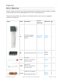
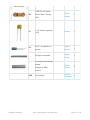
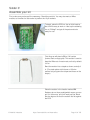
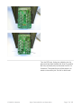
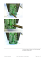
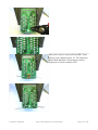
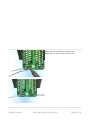
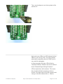
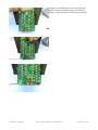
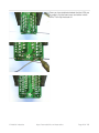
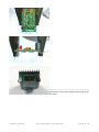
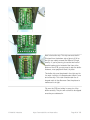
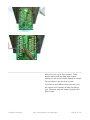
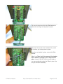
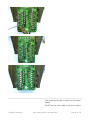
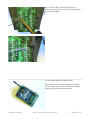
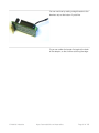
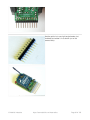
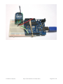
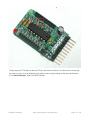
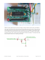
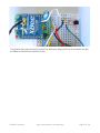
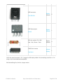
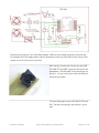
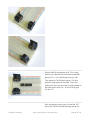
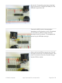
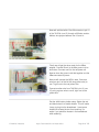
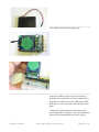
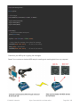
The next component we'll place is the large
electrolytic capacitor. This capacitor helps keep the
3.3V power supply stable even when there are
bursts of usage - such as a data transmit!
Electrolytic capacitors are polarized, just like LEDs.
The longer lead indicates the positive leg and
should go into the pad marked + as shown.
If you're using an XBee Pro and you have a
100uF capacitor you have two options, one is to
solder the capacitor close against the PCB so that
you can bend them a little out of the way for the
xbee pro which is a little long. The other option is to
bend them completely at a right angle so that they
are laying 'facedown' on the PCB. The 47uF
capacitor is small enough it doesn't need to be bent
down.
Once the electrolytic capacitor is in place, insert the
3.3V regulator and the smaller ceramic capacitor
as well. The small ceramic capacitor helps filter out
high frequency noise from the power supply and
the regulator turns the 5V input into a nice & steady
3.3V that the XBee requires.
The ceramic capacitor is non-polar, so place it
'either way.'
Then grab the MCP1700-33 regulator. The 3.3V
regulator must be placed correctly, but is easy to
do: simply match the shape on the silkscreen with
the semicircle of the regulator.
If you're using an XBee Pro you have two
options, one is to solder the regulator close
against the PCB so that you can bend it a little out
of the way for the xbee pro which is a little long.
The other option is to bend it completely at a right
angle so that they are laying 'facedown' on the
PCB.
© Adafruit Industries
https://learn.adafruit.com/xbee-radios
Page 24 of 105