1
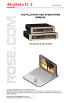
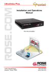
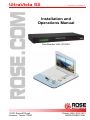
UltraVista SX VIDEO WALL CONTROLLER Installation and Operations Manual Part Number VWL-S122DV 10707 Stancliff Road Houston, Texas 77099 Phone: (281) 933-7673 WWW.ROSE.COM WARRANTY Rose Electronics® warrants the UltraVista™ SX to be in good working order for one year from the date of purchase from Rose Electronics or an authorized dealer. Should this product fail to be in good working order at any time during this one-year warranty period, Rose Electronics will, at its option, repair or replace the Unit as set forth below. Repair parts and replacement units will be either reconditioned or new. All replaced parts become the property of Rose Electronics. This limited warranty does not include service to repair damage to the Unit resulting from accident, disaster, abuse, or unauthorized modification of the Unit, including static discharge and power surges. Limited Warranty service may be obtained by delivering this unit during the one-year warranty period to Rose Electronics or an authorized repair center providing a proof of purchase date. If this Unit is delivered by mail, you agree to insure the Unit or assume the risk of loss or damage in transit, to prepay shipping charges to the warranty service location, and to use the original shipping container or its equivalent. You must call for a return authorization number first. Under no circumstances will a unit be accepted without a return authorization number. Contact an authorized repair center or Rose Electronics for further information. ALL EXPRESS AND IMPLIED WARRANTIES FOR THIS PRODUCT INCLUDING THE WARRANTIES OF MERCHANTABILITY AND FITNESS FOR A PARTICULAR PURPOSE, ARE LIMITED IN DURATION TO A PERIOD OF ONE YEAR FROM THE DATE OF PURCHASE, AND NO WARRANTIES, WHETHER EXPRESS OR IMPLIED, WILL APPLY AFTER THIS PERIOD. SOME STATES DO NOT ALLOW LIMITATIONS ON HOW LONG AN IMPLIED WARRANTY LASTS, SO THE ABOVE LIMITATION MAY NOT APPLY TO YOU. IF THIS PRODUCT IS NOT IN GOOD WORKING ORDER AS WARRANTIED ABOVE, YOUR SOLE REMEDY SHALL BE REPLACEMENT OR REPAIR AS PROVIDED ABOVE. IN NO EVENT WILL ROSE ELECTRONICS BE LIABLE TO YOU FOR ANY DAMAGES INCLUDING ANY LOST PROFITS, LOST SAVINGS OR OTHER INCIDENTAL OR CONSEQUENTIAL DAMAGES ARISING OUT OF THE USE OF OR THE INABILITY TO USE SUCH PRODUCT, EVEN IF ROSE ELECTRONICS OR AN AUTHORIZED DEALER HAS BEEN ADVISED OF THE POSSIBILITY OF SUCH DAMAGES, OR FOR ANY CLAIM BY ANY OTHER PARTY. SOME STATES DO NOT ALLOW THE EXCLUSION OR LIMITATION OF INCIDENTAL OR CONSEQUENTIAL DAMAGES FOR CONSUMER PRODUCTS, SO THE ABOVE MAY NOT APPLY TO YOU. THIS WARRANTY GIVES YOU SPECIFIC LEGAL RIGHTS AND YOU MAY ALSO HAVE OTHER RIGHTS WHICH MAY VARY FROM STATE TO STATE. NOTE: This equipment has been tested and found to comply with the limits for a Class B digital device, pursuant to Part 15 of the FCC Rules. These limits are designed to provide reasonable protection against harmful interference when the equipment is operated in a commercial environment. This equipment generates, uses, and can radiate radio frequency energy and, if not installed and used in accordance with the instruction manual, may cause harmful interference to radio communications. Operation of this equipment in a residential area is likely to cause harmful interference in which case the user will be required to correct the interference at his own expense. IBM, AT, and PS/2 are trademarks of International Business Machines Corp. Microsoft and Microsoft Windows are registered trademarks of Microsoft Corp. Any other trademarks mentioned in this manual are acknowledged to be the property of the trademark owner. Copyright Rose Electronics 2010. All rights reserved. No part of this manual may be reproduced, stored in a retrieval system, or transcribed in any form or any means, electronic or mechanical, including photocopying and recording, without the prior written permission of Rose Electronics. Rose Electronics Part # UV-SX Printed In the United States of America – 1.0 TABLE of CONTENTS Contents Page # Disclaimer ...................................................................................................... 1 System Introduction ....................................................................................... 1 Features ..................................................................................................... 2 Package Contents ...................................................................................... 2 Rose Electronics web site .......................................................................... 2 Product Registration................................................................................... 2 System Overview ........................................................................................... 3 UltraVista SX MODEL.................................................................................... 3 UltraVista SX Installation ............................................................................... 4 Operation ....................................................................................................... 5 System Troubleshooting ................................................................................ 6 Safety ............................................................................................................. 7 Service Information ........................................................................................ 8 Maintenance and Repair ............................................................................ 8 Technical Support ...................................................................................... 8 Figures Page # Figure 1. Installation Diagram ........................................................................ 4 Appendices Page # Appendix A- General Specifications .............................................................. 9 Appendix B- Part Numbers .......................................................................... 10 INTRODUCTION Disclaimer While every precaution has been taken in the preparation of this manual, the manufacturer assumes no responsibility for errors or omissions. Neither does the manufacturer assume any liability for damages resulting from the use of the information contained herein. The manufacturer reserves the right to change the specifications, functions, or circuitry of the product without notice. The manufacturer cannot accept liability for damages due to misuse of the product or other circumstances outside the manufacturer’s control. The manufacturer will not be responsible for any loss, damage, or injury arising directly or indirectly from the use of this product. System Introduction Thank you for choosing the Rose Electronics UltraVista™ SX. The UltraVista SX is the result of Rose Electronics commitment to providing state-of-the-art solutions for today’s demanding workplace. The UltraVista SX has proven to be a valuable investment for any home, business or office that has a need to quickly and easily display a single video source on four monitors, each showing ¼ of the original image. The advanced design of the UltraVista SX supports a DVI-D single-link video input resolution from 800 x 600 up to 1920 x 1200. This input resolution is maintained on all output monitors, producing a perfect image. VGA monitors are supported using a DVI/VGA adapter. Be more productive, creative and organized with the dynamic new UltraVista SX 2x2 Video wall unit from Rose Electronics. INSTALLATION and OPERATIONS MANUAL 1 Features Single-Link DVI-D input Supports analog and digital LCD displays Supports resolutions from 800 x 600 to 1920 x 1200 / 1080 p/i Input source is displayed on 4 displays, each showing ¼ of the image (2 x 2 video wall) Easy, simple installation No additional hardware or software needed Learn mode for obtaining the DDC specifications (DDC table) from a PC, Mac, or from the connected monitors Ideal for: Video walls Information displays Training / education centers Convention centers And many more applications Package Contents The package content consists of the following: The UltraVista SX unit Power adapter Documentation CD (Datasheet, Manual, QuickStart) Rose Electronics web site Visit our web site at www.rose.com for additional information on the UltraVista SX and other products offered by Rose Electronics that are designed for data center applications, classroom environments, digital wall/signage displays, industrial / military systems, and many other access and switching applications. Product Registration Take advantage of the following when you register your Rose Electronics products online at www.rose.com/htm/online-registrationform.htm. 2 Rose Electronics standard warranty Plus . . . . Free Lifetime Firmware Updates Free Lifetime Technical Support 30 day Money Back Guarantee Priority “First-in-Line” Status for Technical Support INSTALLATION and OPERATIONS MANUAL OVERVIEW System Overview The UltraVista SX is a versatile and dynamic video wall system that can be easily and quickly set up in almost any location. The UltraVista SX can take any DVI-D source (video or image) and display it on a 2x2 video array. Each display monitor shows ¼ of the original video source using real-time scaling while maintaining the original resolution on all monitors. Resolutions from 800 x 600 to 1920 x 1200 are fully supported for both analog and DVI LCD displays. UltraVista SX can “learn” the DDC information you wish to use. Using the front display panel and selector buttons, you can choose to “learn” the specifications from a PC, a Mac, or the screen. Once the unit has learned the monitor specifications, it will emulate the monitors even if no monitors are connected. This allows you to make changes or set-up a new presentation without displaying your work on the video wall. UltraVista SX MODEL Front View 2x20 LCD Display Screen Scroll – Push button Enter – Push button Rear View Connectors DVI-I Male (1-DVI in / 4-DVI out) RS232 – Serial Control Power – +5VDC-3A INSTALLATION and OPERATIONS MANUAL 3 INSTALLATION UltraVista SX Installation Installation of the UltraVista SX consists of: 1. Connect your single-link DVI-D video source to the DVI-I input connector on the rear panel of the UltraVista SX using a DVI-D mm cable. (Optionally, connect to a 1x2 DVI video splitter as shown) (NOTE: The connectors on the UltraVista SX are DVI-I connectors but the input video must be single-link DVI-D) 2. Connect four displays to the output connectors on the rear panel. If the displays are VGA displays, a DVI to VGA adapter must be used. 3. Connect the provided power adapter to the UltraVista SX unit and apply power. Use only the provided power adapter. UltraVista SX Optional 1x2 Video Splitter Figure 1. Installation Diagram When all connections are completed and power applied to UltraVista SX, monitors, optional video splitter, and the PC, UltraVista SX will perform a self test to verify that the unit is functioning properly. Upon a successful test, the unit will recognize the video input and display the image on the four monitors. The UltraVista SX supports multiple DDC tables for a PC or Mac. The unit will emulate the monitors even if no monitors are connected. This “Learn” feature allows the connected computer to boot without the displays connected. This gives you the ability to manage the display content or modify a presentation without displaying your work on the video wall. 4 INSTALLATION and OPERATIONS MANUAL To set the UltraVista SX up to “Learn” the monitor specifications (DDC), press and hold both the SCROLL and ENTER buttons on the front panel until the set-up menu displays on the front panel LCD screen. Press the SCROLL button to cycle through the options. When the needed Learn mode is displayed (Learn PC, Learn Mac, Learn Screen, or Exit), press Enter to execute the learn function. The unit will obtain the DDC information from the selected source and return to normal operation. Operation The operation of the UltraVista SX is a very easy and simple operation. You will have your 2x2 video wall presentation up and running quickly since there are no unit configuration to perform, no special software to install and learn, and no video card adjustments to make. The most efficient way to operate your UltraVista SX is to connect it up using a 1x2 video splitter as shown in Figure 1. This provides you a local full screen display of your presentation. When you need to perform maintenance or change the presentation you can disconnect the connection from the video splitter to the UltraVista SX and make changes without your work being displayed on the video wall. The versatility of the UltraVista SX makes it easy to incorporate into almost any application. It can be interfaced to a DVI video selector and the selector’s output connected to the unit. This configuration allows easy selection of multiple video sources. Using an 8 to 1 DVI video selector provides you with 8 video sources that can easily be switched to the UltraVista SX and to your 2x2 video wall. INSTALLATION and OPERATIONS MANUAL 5 TROUBLESHOOTING System Troubleshooting No Image on one or more monitors Check that the monitor is turned on Check that the power source for the monitor is turned on Make sure the LCD panel power cables are securely fastened to the monitor and to the power source Check the monitor connection to the UltraVista SX Verify an output image is present from the video source 6 INSTALLATION and OPERATIONS MANUAL SAFETY Safety The UltraVista SX has been tested for conformance to safety regulations and requirements, and has been certified for international use. Like all electronic equipment, the UltraVista SX should be used with care. To protect yourself from possible injury and to minimize the risk of damage to the Unit, read and follow these safety instructions. Follow all instructions and warnings marked on this Unit. Except where explained in this manual, do not attempt to service this Unit yourself. Do not use this Unit near water. Assure that the placement of this Unit is on a stable surface. Provide proper ventilation and air circulation. Keep connection cables clear of obstructions that might cause damage to them. Use only power cords, power adapter and connection cables designed for this Unit. Keep objects that might damage this Unit and liquids that may spill, clear from this Unit. Liquids and foreign objects might come in contact with voltage points that could create a risk of fire or electrical shock. Do not use liquid or aerosol cleaners to clean this Unit. Always unplug this Unit from its electrical outlet before cleaning. Unplug this Unit refer servicing to a qualified service center if any of the following conditions occur: The connection cables are damaged or frayed. The Unit has been exposed to any liquids. The Unit does not operate normally when all operating instructions have been followed. The Unit has been dropped or the case has been damaged. The Unit exhibits a distinct change in performance, indicating a need for service. INSTALLATION and OPERATIONS MANUAL 7 SERVICE Service Information Maintenance and Repair This Unit does not contain any internal user-serviceable parts. In the event a Unit needs repair or maintenance, you must first obtain a Return Authorization (RA) number from Rose Electronics or an authorized repair center. This Return Authorization number must appear on the outside of the shipping container. See Limited Warranty for more information. When returning a Unit, it should be double-packed in the original container or equivalent, insured and shipped to: Rose Electronics Attn: RA__________ 10707 Stancliff Road Houston, Texas 77099 USA Technical Support If you are experiencing problems, or need assistance in setting up, configuring or operating your UltraVista SX, consult the appropriate sections of this manual. If, however, you require additional information or assistance, please contact the Rose Electronics Technical Support Department at: Phone: (281) 933-7673 E-Mail: [email protected] Web: www.rose.com Technical Support hours are from: 8:00 am to 6:00 pm CST (USA), Monday through Friday. Please report any malfunctions in the operation of this Unit or any discrepancies in this manual to the Rose Electronics Technical Support Department. 8 INSTALLATION and OPERATIONS MANUAL APPENDICES Appendix A- General Specifications Input 1 x DVI-D Single-Link Resolution 1920 x 1200 @ 60Hz (DVI-D or VGA) Outputs 4 x DVI or VGA (VGA requires a DVI to VGA adapter) Dimensions W D H 17.0in 7.0in 1.75in 43.2cm 17.8cm 4.45cm Weight 2.3 lbs / 1.04 kg Power Adapter Input 90 VAC to 264 VAC / 47 Hz to 63 Hz Power Adapter Output 5.0VDC / 3.0A Operating Temp. Storage Temp Operating Humidity Approvals INSTALLATION and OPERATIONS MANUAL 9 Appendix B- Part Numbers Part Number Description VWL-S122DV 2 x 2 Video wall CAB-DVIIMMxxx DVI-I male to male cable CAB-DVIDMMxxx DVI-D male to male cable (xxx = length of cable in feet) 10 INSTALLATION and OPERATIONS MANUAL 10707 Stancliff Road Houston, Texas 77099 Phone: (281) 933-7673 WWW.ROSE.COM