1
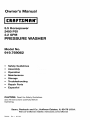
Owner's Manual
i CRRFTSMRN'i
5.5 Horsepower
2400 PSI
2.2 GPM
PRESSURE WASHER
Model No.
919.769062
•
Safety Guidelines
•
Assembly
•
Operation
•
Maintenance
•
Storage
•
Troubleshooting
•
Repair
•
Espao_ol
Parts
CAUTION:
Read the Safety Guidelines
and All Instructions
Operating.
Sears,
D28234
Rev. 1
Carefully Before
Roebuck and Co., Hoffman Estates, IL 60179 U.S.A.
Visit our Craftsman website: www.sears.com/craftsman
6/17/03
hq;1:3nil=iEo_ E_oJ_hnl=l_h_
WARRANTY
.............................................
SPECIFICATION CHART ....................................
2
3
SAFETY GUIDELINES- DEFINITIONS
.........................
IMPORTANT SAFETY INSTRUCTIONS .......................
BOX CONTENTS ..........................................
3
3-7
7
ASSEMBLY ..............................................
OPERATION ...........................................
MAINTENANCE
.......................................
STORAGE ...........................................
TROUBLESHOOTING
GUIDE ............................
8
9-13
f 3-16
17-18
f 8-20
REPAIR PARTS .......................................
HOW TO ORDER REPAIR PARTS ....................
2f-36
Back Cover
r_v/-'1
:! :_±I_bIh'
FULL ONE YEAR WARRANTY
ON CRAFTSMAN
HIGH PRESSURE WASHER
For one year from the date of purchase, when this Craftsman High Pressure
Washer is maintained and operated according to the instructions in the owner's
manual, Sears will repair, free of charge, any defect in material and workmanship.
If your Craftsman Pressure Washer is used for commercial or rental purposes, this
warranty applies only for 90 days from the date of purchase.
FULL TWO YEAR WARRANTY ON CRAFTSMAN ENGINE
For two years from the date of purchase, when this Craftsman engine is maintained
and operated according to the instructions in the owner's manual, Sears will repair,
free of charge, any defect in material and workmanship.
If your Craftsman engine is used for commercial or rental purposes, this warranty
applies only for 90 days from the date of purchase. This warranty does not cover
expendable items such as spark plugs and air filters, which become worn during
normal use.
Repairs necessary because of operator abuse or negligence, including damage
resulting from no water being supplied to pump or failure to maintain the
equipment according to the instructions contained in the owner's manual, are not
covered under warranty.
WARRANTY SERVICE IS AVAILABLE BY RETURNING THE HIGH PRESSURE
WASHER TO THE NEAREST SEARS SERVICE CENTER THROUGHOUT THE
UNITED STATES. This warranty gives you specific legal rights and you may also
have other rights, which vary from state to state.
Sears, Roebuck and Co., D/817 WA, Hoffman Estates, IL 60179
D28234
2- ENG
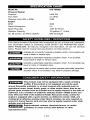
Model No.
Pressure Washer
Pressure
Flow Rate
919-769062
Cleaning Units (PSI x GPM)
Engine
RPM
5280
Rated Horsepower
Spark Plug Gap
Gasoline Capacity
5.5
.030" (0.76mm)
.29 gallons (1.1 liters)
Oil .58 quarts ( .55 liters) capacity
SAE 30 weight
2400 PSi
2.2 GPM
3600
This manual contains information that is important for you to know and understand.
This information relates to protecting YOUR SAFETY and PREVENTING EQUIPMENT PROBLEMS. To help you recognize this information, we use the symbols
below. Please read the manual and pay attention to these sections.
indicates an imminently hazardous situation which, if not avoided, will
result in death or serious injury.
indicates a potentially hazardous situation which, if not avoided,
could result in death or serious injury.
indicates a potentially hazardous situation which, if not avoided,may
result in minor or moderate injury.
used without the safety alert symbol indicates potentially hazardous
situation which, if not avoided, may result in property damage.
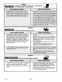
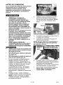
_This
product may not be equipped with a spark arresting
muffler. If the product is not equipped and will be used
around flammable materials, or on land covered with materials such as
agricultural crops, forest, brush, grass, or other similar items, then an approved spark arrester must be installed and is legally required in the state of
California. It is a violation of California statutes section 130050 and/or sections 4442 and 4443 of the California Public Resources Code, unless the
engine is equipped with a spark arrester, as defined in section 4442, and
maintained in effective working order. Spark arresters are also required on
some U.S. Forest Service land and may also be legally required under other
statutes and ordinances.
reproductive
Engine exhaust contains chemicals known, in certain
quantities, to cause cancer, birth defects or other
harm.
3- ENG
D28234
_Read
Operators Manual. Do not operate equipment until you
have read operators Manual for Safety, Assembly, Operation, and
Maintenance Instructions.
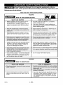
READ AND SAVE THESE INSTRUCTIONS
RISK OF EXPLOSION HAZARD
OR FIRE
WHAT CAN HAPPEN
HOW TO PREVENT IT
• Spilled gasoline and it's vapors can become ignited from cigarette sparks,
electrical arcing, exhaust gases, and hot
engine components such as the muffler.
• Shut off engine and allow it to cool before
adding fuel to the tank.
• Operating the pressure washer in an explosive environment could result in a fire.
• Operate and fuel equipment in weiI vendiated
areas free from obstructions. Equip areas with
fire extinguisher suitable for gasoline fires.
• Muffler exhaust heat can damage painted
surfaces, melt any material sensitive to
heat (such as siding, plastic, rubber, or
vinyl), and damage live ptants.
• Always keep pressure washer a minimum of
four feet away from surfaces (such as houses,
automobiles, or live plants) that could be damaged from muffler exhaust heat.
•
•
•
Use of acids, toxic or corrosive chemicals,
poisons, insecticides,
or any kind of flammable solvent with this product could resuit in serious injuP/or death.
Use care in filling tank to avoid spilling fuel
Move pressure washer away from fueling area
before starting engine.
DO not spray flammable
HAZARD
¢'.,_'"
RISK TO BREATHING
_:_
HOW TO PREVENT IT
WHAT CAN HAPPEN
i6j6_ _ 8eAi6]
liquids.
:
basements etC
ii
i
• Some cleaning fluids contain substances
which could cause injury to skin, eyes, or
lungs.
D28234
i
• Use only cleaning fluids specifically recommended for high pressure washers. Follow
manufacturers recommendations. Do ROt
use chlorine bleach or any other corrosive
compound.
4_ ENG
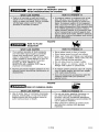
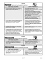
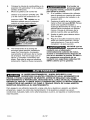
HAZARD
RISK OF INJURY OR PROPERTY DAMAGE
WHEN TRANSPORTING OR STORING
WHAT
CAN
HOW
HAPPEN
TO PREVENT
IT
e _ro_ !eak_
iii
e_ina_i#
HAZARD
RISK
TO FLUID
INJECTION
WHAT
CAN
HAPPEN
HOW
TO PREVENT
IT
• Your washer operates at fluid pressures
and velocities
high enough to penetrate
human and animal flesh, which could
result in amputation
or other serious injury.
Leaks caused by loose fittings or worn or
damaged hoses can result in injection
injuries, DO NOT TREAT FLUID
INJECTION AS A SIMPLE CUT! See a
physician immediateIy!
•
Never place hands
•
•
Direct spray away from self and others.
Make sure hose and fittings are tightened
and in good condition.
Never hold onto the
hose or fittings during operation.
Do not allow hose to contact muffler.
Never attach
or remove
wand or hose
fittings while system is pressurized.
_ inj_bs
_ To reii_
_6
res_i_ if _i_
6_s_re
•
•
i_ _i
s_te_
in front of nozzle.
_re
sh_ _ff _i_!
HAZARD
_RISK
OF CHEMICAL
WHAT
•
CAN
BURN
HAPPEN
Use of acids, toxic or corrosive chemicals,
poisons, insecticides,
or any kind of flammable solvent with this product could resuit in serious injury or death,
HOW
TO PREVENT
IT
•
Do not use acids, gasoline, kerosene, or
any other flammable
materials in this
product. Use only household
detergents,
cleaners and degreasers
recommended
for
use in pressure washers.
•
Wear protective
clothing to protect eyes
and skin from contact with sprayed
materials.
5* ENG
D28234
HAZARD
RISK OF UNSAFE OPERATION
WHAT
CAN
HOW
HAPPEN
TO PREVENT
IT
•
If proper starting procedure
is not
followed, engine can kickback
Causing
serious hand and arm injury.
• If engine does not start after two pulls,
squeeze trigger of gun to relieve pump
pressure. Pull starter cord slowly until
resistance is felt. Then pull cord rapidly
to avoid kickback and prevent hand or
arm injury.
•
Reactive force of spray will cause
gun/wand to move, and could cause the
operator to slip or fall, or misdirect
the
spray, improper
control of gun/wand
can
result in injuries to self and others.
• Do not overreach or stand on an unstable
support, Grip gun/wand firmly with both
hands, Expect the gun to kick when triggered.
HAZARD
RISK OF ELECTRICAL SHOCK
WHAT
CAN
HAPPEN
HOW
TO PREVENT
IT
HOW
TO PREVENT
IT
e{e_trl ca l _hoc
HAZARD
RISK OF HOT SURFACES
WHAT
•
CAN
HAPPEN
Contact with hot surfaces, such as
engines exhaust components,
could
result in serious burn.
D28234
•
6_ ENG
During operation, touch only the control
surfaces of the pressure washer. Keep
children away from the pressure washer at all
times. They may not be able to recognize the
hazards of this product.
HAZARD
_RISK
OF INJURY FROM SPRAY
WHAT CAN HAPPEN
i_!g_iSP_i
i
HOW TO PREVENT IT
iiiiiii ii
against
i i!i ii!i!il
iiii!!
back (o_n)_sition
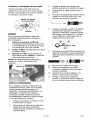
The powerful spray from your pressure washer is capable of causing
damage to surfaces such as wood, glass, automobile paint, auto
striping and trim, and delicate objects such as flowers and shrubs. Before spraying,
check the item to be cleaned to assure yourself that it is strong enough to resist damage
from the force of the spray. Avoid the use of the concentrated spray stream except for
very strong surfaces like concrete and steel.
Operating without flow of water will result in equipment damage. Operating the pressure
washer with water supply shutoff will void your warranty. You should never run this pressure washer for more than 2 minutes without pulling the trigger to allow cool water to
enter the pump and the heated (recirculated) water to exit.
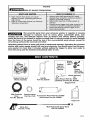
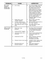
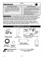
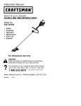
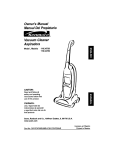
Knobs
English/
Spanish
Operator's
Manual
16471
Part No.l_
Saddle
Bolts Part
No. D23196
_'-Engine Frame and
Wheel Assembly
Handle
Part NO. D22316
O
High Pressure Chemical Hose
Part No= H140
Hose
Part NO. D22166
Nozzle K_
Cleaning
Allen Wrench Part No. 16797
Cleanin 9 Tool Part NO, NCT001
Bagged Parts
Accessories Panel Part NO. D21865
with Screws Part No. D22g01
Engine Oil
....
E
Mu_i-Adjustable
4_
Spray
Part
NO. Gun
17780
Part
7÷ ENG
No.
Spray
Wand
D23314
D28234
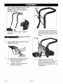
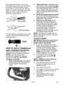
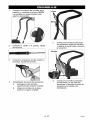
I,
Place handle assembly onto frame
and connect handle to frame,
NOTE: Knobs are assembled to
inside of frame.
Remove
q
.oosel
l
C.
2,
Connect wand to gun. Tighten
securely.
Place grooves in accessories
panel assembly onto screws
and slide panel assembly into
place.
Screws
3,
5,
D28234
Attach high pressure hose to gun.
Tighten securely.
To Assemble Accessories Panel
a,
Remove top screws on
handle assembly.
b. Loosen bottom screws on
handle assembly.
d.
8* ENG
Place screws (removed
earlier) into the top holes and
secure accessories panel
assembly to handles. Do not
overtighten.
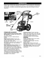
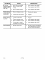
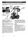
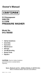
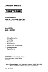
READ THIS OPERATION MANUAL AND SAFETY RULES BEFORE OPERATING
YOUR UNIT. Compare the illustrations with your unit to familiarize yourself with
the location of various controls and adjustments. Save this manual for future
reference.
Chemical
High
Air Filter
Engine
Lever
MultiAdjustable
Spray Wand
High
Pump
PRESSURE
WASHER
High Pressure Pump (located inside
the shroud): Increases the pressure of
the water supply.
Engine: Drives the high pressure
pump.
High Pressure Hose: Carries the
pressurized water from the pump to
the gun and spray wand.
Spray Gun: Connects with spray wand
to control water flow rate, direction,
and pressure.
Multi-Adjustable Spray Wand: Has a
spray nozzle which adjusts from a
pencil stream (0°) to a wide angle fan
spray (40°). The spray can be adjusted
by twisting the nozzle clockwise
and/or counterclockwise. Also, the
high and low pressure settings can be
controlled by moving the nozzle in and
out. See How To Use Spray Wand
paragraph in this section.
Chemical Hose: Feeds cleaning
agents into the pump to mix with the
pressurized water. See How To Apply
Chemicals/Cleaning Solvents in
Operation section of this manual.
ENGINE
Choke Control: Opens and closes
carburetor choke valve
Throttle Control Lever: Controls
engine speed.
Starter Grip: Pulling starter grip
operates recoil starter to crank engine.
Fuel Valve Lever: Opens and closes
connection between fuel tank and
carburetor.
9 * ENG
D28234
TO ADJUST PRESSURE
PRESSURE WASHER
TERMINOLOGY
PSh Pounds per Square Inch. The unit
of measure for water pressure. Also
used for air pressure, hydraulic
pressure, etc.
GPM: Gallons Per Minute. The unit of
measure for the flow rate of water.
CU: Cleaning Units. GPM multiplied
PSI.
The pressure setting is preset at the
factory to achieve optimum pressure
and cleaning. If you need to lower the
pressure, it can be accomplished by
these methods.
1.
by
Bypass Mode: In Bypass Mode, the
pump is recirculating water because
the trigger of the spray gun is not
pulled. If unit is left in bypass mode for
more than two (2) minutes, the water
temperature will rise to a dangerous
level and could damage internal
components of the pump. Any
damage to pump due to these causes
will not be covered under warranty.
DO NOT allow your
unit to operate in
bypass mode for more than two
minutes at any time. Overheating of
pump can cause damage to pump.
Thermal Relief Valve: In an effort to
prevent extreme damage, pumps are
equipped with a thermal relief valve.
This valve will open when the
temperature inside the pump rises too
high. This valve will then release a
gush of water in an effort to lower the
temperature inside the pump.
Immediately after this occurs, the
valve will close. The thermal relief
valve is part of the pump and is not
visible to the user.
Chemical Injection System: Mixes
cleaners or cleaning solvents with the
water to improve cleaning effectiveness.
Water Supply: All pressure washers
must have a source of water. The
minimum requirements for a water
supply are 20 PSI and 5 gallons per
minute.
2.
DO NOT attempt to
increase pump
pressure. A higher pressure setting
than the factory set pressure may
damage pump.
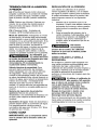
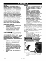
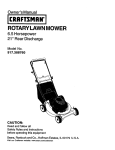
HOW TO USE SPRAY WAND:
Your pressure washer is equipped with
a multi-adjustable spray wand with
both high and low pressure settings.
The high pressure setting is for
cleaning and rinsing, the low pressure
setting is for applying chemicals or
cleaning solutions to surfaces.
I1_
When using the high
pressure setting, DO
NOT allow the jet-like spray to come
in contact with unprotected skin,
eyes, or with any pets or animals.
Serious injury can occur.
I_
NOT
direct
Risk of injection
or
injury to person. DO
discharge
stream toward
persons.
For high pressure operation, pull back
the nozzle of the multi-adjustable
spray wand as shown.
HOW TO USE
IMPORTANT: Read and understand
how to use the pressure washer
before operating.
D28234
Back away from the surface to
be cleaned. The further away you
are, the less the pressure will be
on the surface to be cleaned.
Rotate the nozzle at the end of
the multi-adjustable spray wand
to widen the fan spray, The
wider fan spray will minimize the
pressure on the surface to be
cleaned.
10- ENG
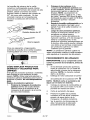
The nozzle at the end of the multiadjustable spray wand can be rotated
to change the high pressure spray
pattern from a narrow jet to a 40 ° fan
shape, as shown. Markings have been
placed on the nozzle to help you
select the spray pattern.
For low pressure operation, extend the
nozzle of the multi-adjustable spray
wand as shown.
HOW TO APPLY CHEMICALS
AND CLEANING
SOLVENTS
Applying chemicals or cleaning
solvents is a low pressure operation.
NOTE: Use only soaps and
chemicals designed for pressure
washer use. Do not use bleach.
To Apply chemicals:
1. Press chemical hose onto barbed
fitting located near high pressure
hose connection of pump as
shown.
2.
Place other end of chemical hose
with filter on it into container holding
chemical/cleaning solution. NOTE:
The chemical/water ratio is 7:1, for
every 7 gallons of water pumped 1
gallon of chemical/cleaning solution
will be used.
3.
Install low pressure (black) nozzle
into quick connect fitting of spray
wand, see How To Use Spray Wand
paragraph in this section.
4. After use of chemicals, place
chemical hose into container of
clean water and draw clean water
through chemical injection system
to rinse system thoroughly. If
chemicals remain in the pump it
could be damaged. Pumps
damaged due to chemicals will not
be covered under warranty.
NOTE: Chemicals and soaps will not
siphon when spray wand is in the high
pressure setting.
TO SHUT DOWN
IMPORTANT: Read and understand
how to shut down the pressure
washer before operating.
1. If you have applied chemicals,
place chemical hose into container
of clean water and draw clean
water through chemical injection
system to rinse system thoroughly.
NOTE: Failure to do so could
cause damage to the pump.
2. Turn engine off by placing the
throttle control in the OFF _1
position.
NOTE: NEVER turn the water off
with the engine running.
3. Turn the fuel valve to the OFF
position if engine will not be
restarted soon.
4.
Turn water source off.
5.
Pull trigger on spray gun to relieve
any water pressure in hose or
spray gun.
See Storage section in this
manual for proper storage
procedures.
6.
1 1 * ENG
D28234
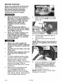
BEFORE
STARTING
Read and understand all Important
Safety Instructions in the front of
this manual and the following
Cautions and Warnings before
starting the pressure washer.
•
•
•
Filler cap/dipstick
Never fill fuel tank completely.
Fill tank to 1/2" below bottom of
filler neck to provide space for
fuel expansion. Wipe any fuel
spillage from engine and
equipment before starting
engine.
Never fill fuel tank indoors.
Never fill fuel tank when engine
is running or hot. Do not smoke
when filling fuel tank.
Never run engine indoors or in
enclosed, poorly ventilated
areas. Engine exhaust contains
carbon monoxide, an odorless
and deadly gas.
{*-1,_11/i
[,] _
•
Never turn water supply off
while pressure washer engine is
running or damage to pump will
result.
•
DO NOT use hot water, use cold
water only.
DO NOT stop spraying water for
more than two minutes at a
time.
In a well ventilated outdoor area
add fresh, high quality, unleaded
gasoline with a pump octane
rating of 86 or higher. Do not
overfill. Wipe up spilled fuel before
starting the engine. Refer to
Engine Owners Manual for correct
procedure.
Remove filler cap/dipstick and
add engine oil (supplied) to
engine. NOTE: There will be a
slight amount of oil in the engine
from factory testing. Always check
oil level before each start-up.
•
1.
2.
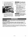
D28234
3.
Verify the filter screen is in water
inlet of pump. NOTE: Cone side
faces out.
Filter Screen
4.
Connect high pressure hose to
pump outlet.
5. Connect water source to pump
inlet.
NOTE: Water source must provide a
minimum of 5 gallons per minute at
20 p.s.L
6.
If you are applying a chemical or
cleaning solution, See How To
Siphon Chemicals/Cleaning
Solvents in Operation section of
this manual.
7. Turn water source on.
NOTE: Failure to do so could cause
damage to the pump.
12_ ENG
8.
9.
Turn fuel valve to the ON position,
1/4 turn counterclockwise.
Move the choke control lever to
the CHOKE ON N position and
the throttle control to the FAST
position. NOTE: No choke is
needed to start a warm engine.
10. Pull starfer grip slowly until you
feel resistance, then pull briskly.
Return starter grip gently. Pull
rope with a rapid full arm stroke.
Let rope rewind slowly. Repeat if
necessary.
If the engine does
not start after two
pulls, pull the trigger to relieve the
pressure.
11. If the choke was used to start the
engine, move the choke lever to
the OFF position.
12. Depress trigger on gun to start
water flow. NOTE: Stand on a
stable surface and grip
gun/spray wand firmly with both
hands. Expect the gun to kick
back when triggered.
13. Release trigger to stop water flow.
14. Adjust nozzle spray for the task
being performed. See How To
Use Spray Wand instructions in
this section.
DO NOT let hoses
come in contact with
very hot engine muffler during or
immediately
after use of your
pressure washer.
When performing maintenance, you may be exposed to hot
surfaces, water pressure, or moving parts that can cause
serious injury or death!
Before performing any maintenance or repair, disconnect spark plug wire,
let engine cool and release all water pressure. The engine contains
flammable fuel. DO NOT smoke or work near open flames while performing
maintenance.
To ensure efficient operation and longer life of your pressure washer, a routine
maintenance schedule should be prepared and followed. If the pressure washer is
used in unusual conditions, such as high-temperatures
or dusty conditions, more
frequent maintenance checks will be required.
13- ENG
D28234
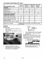
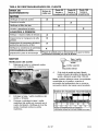
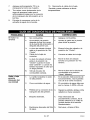
CUSTOMER
RESPONSIBILITIES
MAINTENANCE
TASK
TABLE
Before
each use
ENGINE
check oil level
Every 25
hours or
yearly
Every 50
hours or
yearly
Every 100
hours or
},early
X
change oil
X
check air filter
clean/replace
X
spark plug
X
PRESSURE WASHER
check/clean
inlet screen
X
check high pressure hose
X
check soap and chemical
hose and filter
X
check gun and wand for leaks
X
prepare for storage
Prepare unitfor storageif it isto remainidlefor longer
than 30days
ENGINE
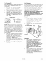
To Check Oil
1.
2.
Shut down engine and place on a
level surface.
Remove filler cap/dipstick and wipe
it clean.
Filler cap/dipstick
Cap/Dipstick
Upper il Limit
Filler
Limit
4.
If the oil level is low, fill to the edge
of the oil filler hole with the SAE
10W-30 oil.
NOTE: Other viscosities shown in the
chart may be used when the average
temperature in your area is within the
recommended range.
SAE Viscosity
:_20
3.
o28234
0
20
;-3o -2o 4o
insert and remove the filler
cap/dipstick without screwing it
into the filler neck. Check the oil
level shown on the dipstick.
3240
8
Grades
60
1o
80
14- ENG
100
2o 3o 4o
STARTING TEMPERATURES RANGE
ANTiCiPATED BEFORE NEXT OiL CHANGE
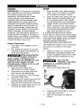
To Change Oil
Air Cleaner
Drain the engine oil when the engine is
warm. Warm oil drains quickly and
completely.
1. Turn the fuel valve to the OFF
position, 1/4 turn clockwise.
2. Place a suitable container next to
the engine to catch the used oil.
3. Remove filler cap/dipstick and
drain the oil into the container by
tipping the engine toward the oil
filler neck.
A dirty air cleaner will restrict air flow to
the carburetor and cause poor engine
performance. Inspect the filter each
time the engine is operated. Clean the
filter more frequently if the engine is
operated in very dusty areas.
Oil Filler Neck
/_._
Oil Filler
_i
Upper
Limit
Cap/Dipstick
wer Limit
NOTE: Please dispose of used motor
oil in a manner that is compatible with
the environment. It is recommended to
take used oil in a sealed container to
your local recycling center or service
station for reclamation. Do not throw it
in the trash or pour it on the ground or
down a drain.
4.
5.
With the engine in a level position,
fill to the upper limit mark on the
dipstick with SAE 10W-30 oil
Engine oil capacity is 0.58 quart
(.055 liter). NOTE: Other
viscosities shown in the chart in
the "To Check Oil" paragraph may
be used.
Replace the oil filler cap/dipstick
securely.
NOTICE: Operating the engine without
a filter, will allow dirt to enter the
engine, causing rapid engine wear. This
type of damage is not covered under
the warranty.
Inspect
1. Press the latch tabs on the top of
the air cleaner cover and remove
the cover. Check the filter to be
sure it is clean and in good
condition.
2. Reinstall the filter and air c]eaner
cove_
Air Cleaner
Body
Fiiter
Air
Cleaner
Air Duct
Cleaning
1. Tap the filter several times on a
hard surface to remove dirt or
blow compressed air [not
exceeding 30 psi (207kPa, 1.2
kg/cm 2] through the filter from the
clean side that faces the engine.
Never try to brush off dirt.
Brushing will force dirt into the
fibers.
2.
15- ENG
Wipe dirt from the air cleaner body
and cover using a moist rag. Be
careful to prevent dirt from
entering the air duct that leads to
the carburetor.
D28234
Clean and Replace Spark Plug
Change the spark plug every 100 hours
of operation or once each year,
whichever comes first. This will help
your engine to start easier and run
better.
3.
Pull trigger on gun handle to
relieve any water pressure.
4.
Disconnect
gun.
5.
Remove the nozzle from the end
of the wand with the 2mm allen
wrench provided as shown.
6.
Clean the nozzle using the nozzle
cleaner provided or a straightened
paper clip. Insert into the nozzle
end and work back and forth until
obstruction is removed.
.030" (0.76 MM)
Resistor
PUMP
This screen filter should be checked
periodically and cleaned if necessary.
1.
Remove filter by grasping end and
removing it from water inlet of
pump as shown.
2.
Clean filter by flushing it with water
on both sides.
3.
Re-insert filter into water inlet of
pump. NOTE: Cone side faces
out.
7.
NOTE: Do not operate pressure
washer without filter properly installed.
8.
9.
the wand from the
Direct water supply into nozzle
end to backflush loosened
particles for 30 seconds.
Reconnect spark plug wire.
Reassemble the nozzle to the
wand. Tighten securely to prevent
leaks.
10. Reconnect wand to gun and turn
on water supply.
11. Start pressure washer and place
wand into high pressure setting to
test.
WAND
If the nozzle becomes clogged with
foreign materials, such as dirt,
excessive pressure may develop. If the
nozzle becomes partially clogged or
restricted, the pump pressure will
pulsate. Clean the nozzle immediately
using the nozzle kit supplied and the
following instructions:
1. Shut off the pressure washer and
turn off the water supply.
2. Disconnect spark plug wire.
D28234
16- ENG
ENGINE
PUMP
IMPORTANT: It is important to prevent
gum deposits from forming in essential
fuel system parts such as the
carburetor, fuel filter, hose or tank
during storage. Also, experience
indicates that alcohol-blended fuels
(called gasohol or using ethanol or
methanol) can attract moisture which
leads to separation and formation of
acids during storage. Acidic gas can
damage the fuel system of an engine
while in storage. To avoid engine
problems, the fuel system should be
emptied before storage of 30 days or
longer. Never use engine or carburetor
cleaner products in the fuel tank or permanent damage may occur.
1.
Engine Preparation
1. First add a fuel stabilizer to the
fuel tank.
2.
Run pressure washer for a full 5
minutes to allow fuel stabilizer to
enter the fuel system.
While preparing the
engine make sure
water supply is turned on and
flowing to the unit. NEVER run unit
without water supply running
through pump. Failure to do so will
cause pump damage.
3.
Next shut off engine and
disconnect the water supply.
4.
Disconnect the spark plug wire
and remove the spark plug.
5. Add one teaspoon of oil through
the spark plug hole.
6.
Place rag over spark plug hole and
pull the recoil a few times to
lubricate the combustion chamber.
7. Replace the spark plug, but do not
connect the spark plug wire.
Drain all water from high pressure
hose, coil it, and store it in cradle
of the pressure washer handle.
2. Drain all water from spray gun and
spray wand by holding spray gun
in a vertical position with nozzle
end pointing down and squeezing
trigger. Store in gun/hose holder.
3. Store chemical hose, high pressure
hose, spray gun, and spray wand
so they are protected from damage, such as being run over.
It is recommended that you follow
these steps to protect the internal seals
of the pressure washer when STORING
THE UNIT FOR MORE THAN 30 DAYS
AND/OR WHEN FREEZING
TEMPERATURES ARE EXPECTED.
*RV antifreeze needs to be run through
the pump as outlined in the steps
below.
4.
Obtain a funnel, six ounces of*RV
antifreeze, and approximately 36
inches of garden hose with a male
hose connector attached to one
end.
Use only RV
antifreeze. Any other
antifreeze is corrosive and can
damage pump.
5. Disconnect spark plug wire.
6.
7.
17- ENG
Connect 36 inch length of hose to
water inlet of pump.
Add *RV antifreeze to hose as
shown.
D28234
8.
9.
Pull engine starter rope slowly
several times until antifreeze
comes out of high pressure hose
connection of pump.
Remove short hose from water
inlet of pump.
10. Reconnect spark plug wire.
*Windshield washer fluid may also be
used
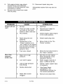
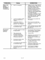
h i ;{olU_';]=[olo_
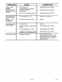
PROBLEM
Engine will not
start
CAUSE
D28234
CORRECTION
No fuel.
1.
Add Fuel.
Pressure builds up after
two pulls on the recoil
starter or after initial use.
Not choked.
2.
Squeeze gun trigger to
relieve pressure.
3.
Choke engine, place engine
in the choke position.
4.
Spark plug wire not
attached.
4.
Attach spark plug wire.
5.
Choke lever in the
5.
"Choke" position on a
"hot" engine or an engine
that has been exposed to
thermal heat for a long
period of time.
Move choke to the "No
Choke" position.
6.
Fuel valve closed
6.
Move the fuel valve knob to
the "Open" position.
1.
Wand not in high
pressure.
1.
See How to Use Spray
Wand paragraph in the
Operation Section.
2.
Low water supply.
2.
Water supply must be at
least 5 GPM @ 20 PSI.
3.
Leak at high pressure
hose fitting.
3.
Tighten. Apply sealant tape
if necessary.
4.
Nozzle obstructed.
4.
See Spray Wand
paragraph in the
Maintenance section for
the correct procedure.
5.
Water filter screen
clogged.
5.
Remove and clean filter.
1.
2.
3.
No or low
pressure
(initial use)
[_u] I m]=1
18- ENG
PROBLEM
No or low
pressure
(initial use)
(continued)
CAUSE
6.
Air in hose.
6.
Turn off the engine, then the
water source. Disconnect
the water source from the
pump inlet and turn the
water source on to remove
all air from the hose. When
there is a steady stream of
water present, turn water
source off. Reconnect water
source to pump inlet and
turn on water source.
Squeeze trigger to remove
remaining air.
7.
Choke lever in the
"Choke" position.
Throttle control lever is
not in the "Fast" position.
7.
Move choke to the "No
Choke" position.
Move throttle control lever to
the "Fast" position.
8.
Will not draw
chemicals
CORRECTION
8.
9.
High pressure hose is too 9.
long.
Use high pressure hose
under 100 feet.
1.
Wand not in low
pressure.
1.
2.
Chemical filter clogged.
2.
See Spray Wand paragraph
in the Maintenance section
for the correct procedure.
Clean filter.
3.
Chemical screen not in
chemical
3.
Insure end of chemical hose
is fully submerged into
chemical.
4.
Chemical too thick
4.
Dilute chemical. Chemical
should be the same
consistency as water.
5.
Pressure hose is too long 5.
6.
Chemical build up in
chemical injector.
19- ENG
6.
Lengthen water supply hose
instead of high pressure
hose.
Have parts cleaned or
replaced by AWSC.
D28234
PROBLEM
CAUSE
CORRECTION
No or low
1.
Worn seal or packing.
1.
Have replaced byAWSC.
pressure (after
period of normal use.)
2.
Worn or obstructed
valves.
2.
Have replaced byAWSC.
3.
Worn unloader piston.
3.
Have replaced by AWSC.
Water leaking
at gun/wand
connection
1.
Worn or broken o-ring.
1.
Check and replace.
2.
Loose hose connection.
2.
Tighten.
Water leaking
1.
Loose connections.
1.
Tighten.
at pump
2.
Piston packings worn.
2.
Have replaced byAWSC.
3.
Worn or broken o-rings.
3.
Have replaced by AWSC.
4.
Pump head or tubes
damaged from freezing.
4.
Have replaced by AWSC.
1.
Nozzle obstructed.
2.
See Spray Wand paragraph
in the Maintenance section
for the correct procedure.
Pump Pulsates
D28234
20* ENG
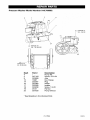
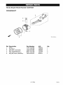
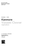
I ;t_ "J._I ;t I"J._;i _
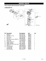
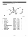
Pressure Washer Model Number 919.769062
/6
7
/
10
TORQUE TC
24
12
TORQUE TO
130 - 150 IN-LSS
15 _
TORQUE TO
25 - 35 IN-LBS
Part #
4
5
9
13
14
16
17
18
19
23
D27152
D23099
16087
D22267
D21963
D22268
D23208
W137
D21630
Description
Pump Kit
Screw, 5/16-24
Axle
Nut, Flange
Plug
Wheel
Isolator
Screw, 1/4-20
Pal Nt_
Pump Shroud
* See Breakdown for individual Parts
21_ ENG
D28234
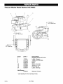
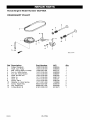
I d =1",2.,_
I d I",2.,_
_ _
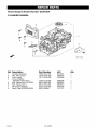
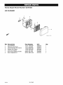
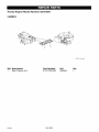
Pressure Washer Model Number 919.769062
/
7
10
24
/
t2
TORQUE TO
130-1501N-LBS
TORQUETO
25_35tN-LBS
1
2
3
6
7
10
12
15
24
17050
D23125
D22908
D25074
D22906
D22308
D22692
D25087
Engine, Honda GCV160
Label, Danger
Label, Hot Surface
Frame
Base
Screw, 5/16-18
Screw, 5/16-18
N_, 5/16-18
Label, Warning
D28234
Manual,Owners
* See Breakdown for individual Parts
D28234
22- ENG
TORQUETO
:1=I",.T:_
1:71
",.T:_
:li
_']
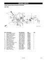
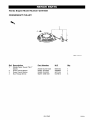
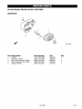
Pressure Pump Model Number D29569
6
2
3
1
2
3
4
5
6
7
P_J_t#
D20998
16355
16848
H061
H068
V161
F187
Hose, 3/8 x 18"
Unloader Assembly
Thermal Relief Valve
Swivel Nut, Garden Hose
Swivel, 3/8"
Chemical injector
Inlet ScreenFilter
Not Shown:
H140
Chemical Hose,
23* ENG
o28234
I ;t =1",.T.,I
I;t I ",.T.,_
;ti I[,.."]
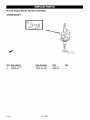
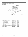
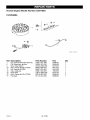
Honda Engine Model Number GCV160A
CYLINDER
BARREL
Zj
R_f_
1
2
3
4
5
8
7
8
Cylinder Assembly
Clip, Valve Guide
Cover, Head
Cover, Breather
(Breather Valve Assy)
Bolt, Flange (6xl 2) (CT20O}
Bolt, Flange (6x14)
Oil Seal (2&4x82xT)
Spark Plug (BPB6ES)(NGK)
D28234
12000-ZL8-405
12216-ZE5_300
12311 *Z£8-900
6315691
2399780
5579990
1
1
1
12355-ZL8-000
90013-883_000
90014_952-000
91201-ZL8_003
98079*56846
5580006
0636845
0803619
5581038
1441112
1
4
1
1
1
24- ENG
1:1=I",.T:_
I:II",.T:_
:li
_
Honda Engine Model Number GCV160A
OIL PAN
Ref
1
2
4
5
6
7
8
9
10
11
12
13
14
15
18
17
18
19
20
21
Pan Assembly, Oil (SAE)
Gasket, Oil Filler Cap
Shaft, Governor Holder
Governor Assembly
Weight Governor
Holder, Governor Weight
Pin, Governor Weight
SLider, Govenor
Shaft, Governor Arm
Bo_t, Flange (6xl 4)
Bo_t, Flange (6x25)
Washer, Thrust (28x41,25x6)
Clip, Governor Holder
O+1Sea+ (28x41.25x6)
Washer, Plain (6mm)
Pin, Lock (8mm)
Pin, Dowel 98c20)
Gauge Assy., Oil Level
Bott, Dra+n PLug
Washer, Drain Plug
PaJ_ Number
11300-ZOL-820
15625-ZE1+003
18508-ZM0+010
18510-ZM0+010
18511-ZL8-000
18512_ZM0+000
18513-ZE1-000
18531ZE1+000
16541-ZM0+000
90014-952_000
90121-952-000
90451 -ZE1-000
90602_zel +000
91202+ZM0+V31
94101-06800
94251-08000
94301-08200
15650-ZM0+003
90131-896-650
94109-12000
25- ENG
_Lv
6696686
4497947
6384341
6384333
5580287
5580295
1427244
1427251
5580303
0803619
0748111
2413862
2456697
6315865
0345900
0115527
1417369
5722996
1988231
0171868
!
!
!
!
2
!
2
!
!
1
8
1
!
1
1
1
2
1
1
1
1328234
Honda Engine Model Number GCVI60A
CRANKSHAFT
I®oo
I _iF_l
Ref
5
8
Descr_tion
Washer, Thrust
Crankshaft
D28234
I
Part Number
98402_ZL8_000
13310_ZOL_650
26- ENG
H/C
_y
5581012
6696702
1
1
Honda Engine Model Number GCV160A
CRANKSHAFT
3
Ref
1
2
3
4
6
6
Piston
Pin, Piston
Rod Assy. Connecting
Bolt, Connecting Rod
CIip, Pistion Pin (13ram)
Ring Set, Piston (TEIKOKU)
13101-ZL8-000
13111*ZE0-000
13200-ZL8-000
90001-ZE1_000
90551-ZE0_000
13010-ZL8-014
27÷ ENG
5580014
1426576
5580022
1431055
2605517
6315717
1
1
1
2
2
1
D28234
I ;t =1",2.,_
I _ I",2.,_
_ t[-_
Honda Engine Model Number GCV160A
CRANKSHAFT
Ref
1
2
3
4
5
6
7
8
9
10
11
12
13
PULLEY
Pulley, Camshaft
Shaft, Cam Pulley
Belt, Timing (84HU7 G*200)
Arm, tn. Valve Rocker
Arm, EX. Valve Rocker
Shaft, Rocker Arm
Valve, In.
Valve, Ex
Spring, Valve
Retainer, In. Valve Spring
Screw, Tappet Adj.
Nut, Tappet Adj.
O-Ring (6.6xl.9)
D28234
Number
14320_ZLS_000
14324_ZL8-000
14400*ZOJ-004
14431 *ZL8*000
14441_ZL8_000
14461 *ZL8*000
14711 *ZL8*000
14721_ZL8_000
14751 *ZL8*000
14771_ZE1_000
90012_333_000
90206_001 _000
91301 *ZMO*V31
28- ENG
_
5580055
5580063
6637417
5580089
5580097
5580105
5580113
5580121
5580139
1426980
0294819
0004598
6315873
(;Lt_
1
1
1
1
1
2
1
1
2
2
2
2
1
I:I=I",.T:_
I:II",.T:_
:li
_']
Honda Engine Model Number GCV160A
CRANKSHAFT
PULLEY
1
!
1
2
Ref
1
2
3
4
_
Starter Assy,, Recoil *NHI*
(black)
Knob, Recoit Starter
Rope, RecoiI Starter
Nut, F_ange (8ram)
Qty
_Number
28400*ZLS*013ZA
28461 -ZLS-OO3
28462-ZL8-003
90201 *ZMO-00O
29* ENG
6061204
5580834
5611454
6478812
!
!
1
3
D28234
I ;] =1",2.,_
I _ I",2.,_
_ Lr_3
Honda Engine Model Number GCV160A
FAN COVER
_104
Ref
1
2
3
4
5
6
8
9
10
11
12
13
14
Rubber, Supporter (107mm)
Petcock Assy, (MAN)
Hracket, Pet¢ock
Cap Assy,, Fuel Tank
Tube, Fuel
Cover, Fan *NHl*(b_ack)
Collar, Fr. Turn Signal
Holt, Stud
Screw_Washer (8x10)
Hulk Hose, Fuel (8.8x800) (&Sx150)
C_ip, Tube (B8)
C_ip, Tube (B10)
CIip, Tube (C9)
D28234
Pa_ Number
!6854_ZH8_000
!6950*ZG9*M02
!6956-ZM0_000
!7620-ZL8-013
17702-ZM0_000
19610*ZM0_010ZA
33600-GK4-620
90043-ZL8-000
93891-05010-08
98001-55008-40M
98002-02080
98002_02100
98002_50000
30_ ENG
H_
3883646
5028923
5580394
6673289
5580469
6132989
2499440
5581004
0871638
2449593
0250647
0250985
0053447
1
1
1
1
1
1
1
3
1
1
1
2
1
Et20_A
I:]=I",.T:_
I:II",.T:_
:li
_
Honda Engine Model Number GCV160A
CARBURETOR
Ref
1
2
3
4
5
6
7
8
9
10
11
12
13
14
15
16
17
Gasket Set
Float Set
Chamber Set, Float
Screw Set
Screw Set 8
Screw Set
Carburetor Assembly (BB62B D)
Valve, Float
Nozzle, Main
Insulator, Carburetor
Gasket, Insulator
Gasket, Carburetor
Gasket, Carburetor (Choke Side)
Guide, Air
Screw, Pan (5x6)
Jet, Main (#60)
Jet, Main (#62)
Jet, Main (#65)
Screw Set, Drain
PaJ_ Number
16010-883-015
16013-ZL1_003
16015-687-782
16016-ZGO-WOO
16028-ZFO-OO5
16029-ZG0-901
16100-ZMO_803
16155-ZM0_003
16166-ZM0_003
16211-ZL8-000
16212_ZL8-000
16221-683-800
16228-ZL8_000
19650-ZMO_O00
93500-05006-0H
99101-124-0600
99101-124-0620
99101-124-0650
16024-ZE1-811
31 * ENG
3088416
5580162
3465879
4481818
1441518
5580170
6212849
5580212
5580220
5580238
5580246
4581120
5580253
5580535
0639419
0635474
0635482
0636126
1672187
1
!
!
1
1
1
1
1
1
1
!
2
!
!
!
1
1
1
1
1328234
1:1=I",.T:_
I:II",.T:_
:li
_
Honda Engine Model Number GCV160A
AIR CLEANER
Ref
1
2
3
5
6
7
8
Description
Tube Breather
Element, Air Cleaner
Case Assemb+y, Air Cleaner
Gasket, Air Cleaner
Cover, Air Cleaner
Bolt, Flange (6x88) (CT200)
Bolt, Flange (6x14)
D28234
Part Number
! 5721+ZM0+000
! 7211 +ZL8+000
17220+ZM0+000
17228+ZM0-000
17231+XOL+000
90003+ZOL+000
95701+06014+08
32_ ENG
H/C
5580154
5580402
5580410
5664560
6673255
5580964
2374742
oty
1
1
1
1
1
2
1
Honda Engine Model Number GCV160A
MUFFLER
4
I
Ref
1
2
3
4
5
Muffler
Protector, Muffler
Bolt, Flange (8x79) (CT200)
Bott, Flange (8x12) (CT200)
Gasket, Muffler
Number
183!0-ZM0-000
18321-ZL8-000
90004-ZL8-000
90013*883*000
18381-ZL8-305
33- ENG
_
5580485
5580501
5580972
0636845
5737457
Qt_
1
!
2
3
1
D28234
Id =1",2.,_
I_ I",2.,_
_ i[-_
Honda Engine Model Number GCV160A
FLYWHEEL
Ref
1
2
4
10
11
12
15
18
17
Description
Key, Special Woodruff (28×18)
Coil Assembly, ignition
Wire, Stop Watch
Bolt, Flange (6x20) (CT200)
Nut, Special (14MM)
Clip, Cable (A)
Plate Side
Bolt, Flange (6xl 2) (CT200)
FlywheeI
028234
Part Number
13331-357_000
30500-ZL8-004
32195-ZM0-800
90022 -688_010
90201-878_003
90681-959-003
19612 -ZM0-000
90013-883-000
31110-ZL8-004
34* ENG
H/C
0348433
5580659
6315816
0671552
0442038
1824630
6315782
0638845
5656053
Qty
!
1
1
1
1
1
1
2
1
Honda Engine Model Number GCV160A
CONTROL (2)
8_
13
Ref
1
2
3
4
5
6
7
8
9
10
11
12
13
14
15
16
17
18
19
20
21
22
Arm, Governor
Rod, Governor
Spring, Governor
Spring, Throttle Return
Spring, Lever
Washer, Control Lever
Plate, Lever Center
Spacer, Control Lever
Base Control
Lever, Choke
Rod, Choke
Collar (9.2xl 5x20.6)
Switch Assembly, Engine Stop (N.O)
Mark, Throttle Indication
Bolt, Governor Arm
Bolt, FIange (6x32)
Bolt, Special (6x45)
Nut, Self*Lock (6MM)
Nut, Self*Lock (6MM)
Screw_Washer (4xl 2)
Nut, FIange (6MM)
Washer, Plain (4MM)
16661-ZM0-000
16665-ZM0-000
16561 -ZMOW3O
16662-ZM0-000
16674-ZE1-000
16675-ZE2-W00
16677-ZM0-V30
16678-ZE1_000
16680-ZMOW30
16612-ZMO-V30
16674_ZM0-V30
91601 _ZM0-V3O
35120-ZL8-003
87632-ZM0-V30
90015-ZE5-010
90017-883-000
90016-ZM0-V60
90114-SAO-OOO
90136-SM4_901
93892-040!2_00
94050-06000
94163-64006
35* ENG
HJ£
Q_
5580311
5580329
6315725
5580352
1427384
3678679
6315741
1427400
6315758
6315766
6315774
6363733
5611520
6315832
2418671
0636076
6315840
1410182
3596095
0485946
0471623
1510361
1
1
1
1
1
1
1
1
1
1
1
1
1
1
1
1
1
1
1
1
!
1
D28234
Honda Engine Model Number GCV160A
LABELS
Ref Description
1
Mark, Emblem (5.5)
D28234
Part Number
87101_ZMO-O00
36- ENG
H/C
5580865
Q,_
1
h q;_:t W:| m}=lifo} _h nl=1_I ImIo_
GARANT|A ...............................................
GRAFICO DE ESPECIFICACIONES
...........................
37
38
PAUTAS DE SEGURIDAD - DEFINICIONES
.....................
INSTRUCCIONES IMPORTANTES DE SEGURIDAD ............
CONTENIDO DE LA CAJA ..................................
ENSAMBLAJE ............................................
OPERACI6N ...........................................
38
38-42
42
43
44-48
MANTENIMIENTO
48-51
ALMACENAJE
......................................
.........................................
GU|A PARA DIAGN(_STICO
DE PROBLEMAS
PIEZAS DE REPARACI{_N ................................
COMO SOUCITAR PIEZAS DE REPARACI(_N
GARANT|A
LAVADORAS
52-53
.................
......
53-55
21-36
Cubierta de atr&s
LIMITADA
DE UN Al_lO PARA
CRAFTSMAN
DE ALTA PRESI(_N
Pot an a_o a partir de la fecha de compra, y siempra que esta Lavadora Craftsman de Alta
Presi6n sa mantenga y opere de acuerdo alas instrucciones en el Manual del Propietario,
Sears reparara cualquier defecto de material o fabricacion sin costo alguno.
Siesta lavadora se usa para prop6sitos comerciales o de alquiler, la garantfa solo ser&
aplicable pot 90 dlas a partir de la fecha de compra.
GARANT|A LIMITADA DE DOS AltOS DEL MOTOR CRAFTSMAN
Pot dos a_os a partir de la fecha de compra, y siempre que este motor Craftsman se mantenga
y opere de acuerdo alas instrucciones en el Manual del Propietario, Sears reparar& cualquier
defecto de material o fabricaciSn sin costo alguno.
Si el motor Craftsman se usa para propSsitos comerciales o de alqaller, la garantla sSIo sar&
aplicable por 90 dfas a partir de la fecha de compra. Esta garantia no cubre piezas sujetas a
desgaste tales como bujias y filtros de airs, los cuales sa gastan con el uso normal.
La garantfa no cubre las reparaciones que se hagan necesarias debido al mal uso o
negligencia de parte del operador, incluyando da_os causados per no suministrade agua a la
bomba o no mantener el equipo de aeaerdo alas instruceiones contenidas en este manual.
SE PUEDE OBTENER SERVICIO POR GARANT[A SI SE LLEVA LA LAVADORA DE ALTA
PRESION AL CENTRO/DEPARTAMENTO DE SERVICIO DE GARANTfA DE SEARS MAS
CERCANO EN CUALQUIER LUGAR DE ESTADOS UNIDOS. Esta garantfa le otorga ciertos
derschos legales especificos y usted tambi_n podrfa taner otros derechos que varian de un
estado a otro.
Sears, Roebuck and Co,, D/817 WA, Hoffman Estates, IL 60179
37+ SP
D28234
€-1-'_,_q
=1[_o] Ira]=I ::[,-:'1
".1::[e]I ;;I[e.]E_e][o] _I ::k
Modelo N°
919-769062
Lavadora a presibn
Presi6n
2400 PSI
Promedio de flujo
Unidades de limpieza (PSI x GPM)
RPM del Motor
8,3 I/m (2.2 GPM)
5280
3600
5.5
Potencia especificada en HP
Luz de bujia
Capacidad del tanque de gasolina
Capacidad de aceite 0,55 litros
(0.58 cuartos de gal6n)
0,76 mm (.030")
1,1 litros (0.29 galones)
SAE 30 de densidad
Este manual contiene informacion
que es impor_ante para que usted sepa y comprenda.
Esta
informacion
se relaciona con la protecci6n
de SU SEGURIDAD
y la PREVENCION
DE PROBLEMAS
AL EQUIPO. Para ayudarle a identificar
esta informaci6n,
utilizamos
abajo. Sirvase leer el manual y prestar atenci6n a los mismos.
indica unala situacibn
causar_
muerte o inminer_emente
lesiones serias. riesgosa,
los simbolos
_
mas
la cual, si no es evitada,
indica
situaci6n
potencialmente
podria una
ocasionar
la muerte
o lesiones riesgosa,
serias.
indica
situaci6n
potencialmente
podria una
ocasionar
lesiones
menores
indicados
que si no es evitada,
oriesgosa,
moderadas.la cual, si no es evitada,
usado
sin el simbolo
de seguridad
indicapodria
una situacibn
potencialmente
riesgosa
la que, si de
no alerta,
es evitada,
causar da_os
en la propiedad.
Este producto podrfa no estar equipado con silenciador
apagachispas. Si el producto no estuviese equipado con ello, y
fuera instalado en las cercan|as de materiales inflamables, o sobre una superficie
cubierta con materiales tales como cosechas agricolas, materiales forestales,
malezas, pasto, u ottos items similares, debera entonces instalatse un silenciador
apagachispas aprobado el eual es legalmente requerido pot el Estado de California. Es
una violacibn a los estatutos de California, secci6n 130050 y / o secciones 4442 y 4443
del Cbdigo de Recursos Pdblicos de California, a menos que el motor se encuentre
equipado con un apagaehispas, tal eomo se Io define en la seccibn 4442, y mantenido
en perfecto estado de funcionamiento.
Los apagachispas tambidn son tequeridos por
el Servicio Forestal de EE.UU., y podrlan set requeridos legalmente bajo otros
estatutos y ordenanzas.
defectos de nacimiento
D28234
El escape del motor contiene productos quimicos conocidos,
que * en ciertas cantidades - pueden ser causales de cancer,
u otros da_os de gestaci6n.
38 * SP
funcionar
Lea el Manual
de funcionamiento.
Para su seguridad,
armado,
funcionamiento
e instrucciones
de mantenimiento_
no haga
hasta habet le|do el Manual
de funcionamiento.
el equipo
LEA Y CONSERVE ESTAS INSTRUCCIONES
RIESGO
RIESGO DE EXPLOSION
QUE
•
•
PUEDE
O INCENDIO
"1"
|
OCURRIR
COMO
PREVENIRLO
La gasolina derramada y sus emanaciones
pueden incendiarse con las chispas de un
cigarriilo, arcos eI_ctdcos, eI escape de la
combusti6n y eomponentes calientes del motor
tales como el silenciador.
•
Hater funcionar la lavadora a presi6n dentro de
un ambiente explosivo podrla ocasionar un
incendio.
•
Haga ful_cionar el equipo y agregue combustible
en _reas bien vent_Ia#as y libre de obstn_cc_es.
Equipe las zonas con extinguideres apropiados
para incendio de gaso_in&
i_ _iqiQ
•
Detenga el motor y perm_tale enfriarse antes de
agregar combustible at tanque.
Ponga sumo ouidado al Ilenar el tanque,
evitando el derramamiento del combustible,
Corra la lavadora a presi6n fuera deI &tea de
cargado de gasolina, antes de poner el motor
en march&
d_los _ at_ riales:
•
El calor del escape del silenciador puede
da_ar superficies pintadas, derretir cuaJquier
material sensible a la temperstura (tal como
revestimientos exteriores, p+&sticos, gomas, o
viniIos), y da,fiar plantas viva&
•
Mantenga siempre la lavadora a presiSn a una
distancia minima de 1.22 m (cuatro pies) de
superficies (tales como casas, automSviles, o
plantas vivas) que podrlan ser daSadas por el
calor del escape del silenciador.
•
E+uso de &cidos, productos qulmicos tSxicos
o eorrosivos, veneno$, insectieidas o cualquier
clase de solventes inflamables con este
prodecto, podrl8 ocasionar una seri8 leside o
la muerfe.
•
No rocle llquidos
inflamables.
RIESGO
RIESGO DE INHALACI(_N
QUEPUEDE
OCURRIR
O()MO
• Algunos fluidos para limpieza contienen
sustancias que pueden lesionar la piel+ los ojos
o los pulmones.
•
39 + SP
PREMENIRLO
Use solamente fluidos pera timpieza
especificamente
recomendados
para lavadoras
a alta presi_n, Siga las recomendaciones
del
fabrioante, No use blanqueador clorado ni
compuesto corrosivo alguno,
D28234
RIESGO
RIESGO
DE LESIONES
O DAI_OS A LA PROPIEDAD
AL TRANSPORTAR
O ALMACENAR.
QU I_ PUEDE OCURRIR
COMO
PREVENIRLO
RIESGO
RIESGO DE INYECCI(_N DE FLUIDO
QUE PUEDE OCURRIR
•
COMO PREVENIRLO
Su Iavadora func_a a presiones de f_uido y
ve_ocidades elevadas, capaces de penetr&r el
tejido hum&no y animat; ello podria determinar
una amputaciSn u otras lesiones serias, Las
p6rdidas causadas pot conexiones flojas o
gastadas, o mangueras da_adas pueden
determinar lesiones pot inyecci6n, iNO TRATE
A LA INYECCION DE FLUIDO COMO A UN
S_MPLE CORTE! iConsulte a un m6dico
+nmediatamentet
•
•
•
•
•
Jam&s coloque sus manos delante de la
boqu+lla,
Dirija el rociado fuera de sl u otras personas,
Asegtlrese que las mangueras y acoples esten
ajustados yen buenas condiciones+ Jam&s
sujete de _aboquit+a o los acoples durante su
funcionamiento.
No permita que la manguera tome contacto
con el silenciador,
Jam&s conecte o desconecte la var+lla
rociadora o los acoplamientos
de manguera
mientras el sistema este presunzado,
RIESGO
_
RIESGO DE QUEMADURA QU|MICA
QU I_ PUEDE
•
OCURRIR
COMO
B uso de &cidos, productos qulmicos t6xicos o
corrosivos, venenos, insecticidas o cua+qu+er
clase de solventes inflamables con este
producto, puede ocasionar una seria lesi6n o la
muerte,
PREVENIRLO
= No utilice Acidos, gasoI+na, keros_n, o cualqu+er
otro m_terial inftamable en este producto.
Util+ce t_nicamente detergentes dom6sticos,
limpiadores y desengrasantes recomendados
para e+uso en lavadoras a presibn,
Use atuendo de proteccibn adecuado para _a
preservacibn de SUS OjOSy pie_ del contacto
con los materiales rociados,
D28234
40* SP
RIESGO DE FUNCIONAMIENTO
INSEGURO
RIESGO
QU le PUEDE
OCURRIR
C()MO
PREVENIRLO
•
Si no se siguen Ios procedimientos
adecuados
para e+ arranque, e+motor puede efectuar un
retroceso de marcha pudiendo ocasionar
serias lesiones en la mano y eI brazo+
•
Si el motor no arrancara despues de dos
intentos, presione el gatilto de la pistola con el
fin de aliviar la presi6n de la bomba. Vuelva a
tirar del cord6n +entame_e hasta percibir
resistencia. Luego tire r&pidame_e del mismo
para evitar el retroceso y prevenir Ia lesi6n en su
mano o bra.zo.
•
Lafuerzareactivadelrociadodeterminar&que
la pistoIWvarilla rociadora se mueva y podria
set la causa de que el operador se resba_e,
caiga, u oriente el rociador hacia una direcci6n
err6nea+ E_ control +nadecuado de la
pistola/var+!la roeiadora puede ocasionar
lesiones a uno mismo u otras personas.
•
No se sobreextienda ni se pare sobre una
superficie inestable+ Sostenga firmemente el
mango de la pistola/variIia rociadora con ambas
manos+ F'revea el retroccso de la pistola cuando
apriete el gatillo+
_
RIESGO DE DESCARGA
ELI_CTRICA
RIESGO
QU le PUEDE
OCURRIR
C()MO
func!_m_ier_t_
_
RIESGO DE SUPERFICIES
CAUENTES
RIESGO
QU le PUEDE
•
OCURRIR
El contacto con superficies calientes, tales
como los componentes
deI escape de
motores, puede ocasionar serias
quemaduras+
41+ SP
#l_ic_
_tes
_
ir_tent_r
=_=
C()MO
•
PREVENIRLO
PREVENIRLO
Durante eI funoionamiento,
toque solamente las
superficies de control de la lavadora a presi6n.
Mantenga a los ni_os alejados en todo
momento de la lavadora a presi6n, Ellos
podrian no darse cuenta de los riesgos de este
producto+
D28234
RIESGO
_
RIESGO DE LESIONES PROVENIENTES
QUE
PUEDE
OCURRIR
DEL ROCIADO
C()MO
_a_nt_
_ _ra
................................................................................
PREVENIRLO
pro_erse
v_lla _iadQra
d_ r_i_
_bidenta_
n_ est_ _ _i
chorro poderoso
de su la
lavadora
presi6n pintara
es capaz
de causar da_o
aEl superficies
tales como
madera, a vidrio,
del autom6vil,
guardas rayadas, adornos y objetos delicados
tales como flores y arbustos. Antes de rociar,
verifique el item que debe ser lavado para asegurarse
que el mismo es suficientementa
fuerte como para resistir el impacto de la fuerza del rociado. Evlte el uso del chorro
concentrado
excepto
para superficies
muy fuertes, tales como concreto
y acero.
Hacer funcionar
el equipo sin el flujo del agua Io da_ar_. Hacer funcionar
la lavadora
a
presi6n con su suministro
de agua cerrado anulard su garantia. No deber_ hacerse
funcionar la lavadora a presi6n pot robs de 2 minutos sin presionar el gatillo que permite
entrar el agua fria a la bombay
saUr el agua caliente (reciclada).
Bastidor y conjunto
de ruedas del motor
Manguera de
alta presibn
Pieza N ° D22166
Perillas
Manillar
propietario
(Ingles
Castallano)
Pieza
16471 N_I_
_
_,__
Juego de
_1_
Bulones
montantes
Pieza N °
D23196
Embalaje
de partas
Panel de accesorios
Pieza N ° D21865
con tornillos pieza N ° D22901
Manguera de
productos
qulmicos
Pieza N ° H140
Aceite para
motor
.... E
"_:XI
Varilla rociadora multirregulable
Pieza N ° D23314
D28234
_
limpieza para la
boquilla
Llave Allen, Pieza N ° 16797
Herramienta de limpieza, pieza N° NCT001
Pieza N ° D22316
0
Manual del
42- SP
Coloque el cenjunto del manillar en el
bastidor y conectelo al mismo. NOTA:
Las perillas son ensambladas hacia
adentro del bastidor.
Retire
g
Afloja
\
J
c.
2.
Conecte la varilla a la pistol&
firmemente.
Ajuste
Coloque las muescas del panel
de accesorios sobre los tomillos
y deslice el panel basra colocarlo
en posici6n.
Tornillos
I
3.
Conecte la manguera de alta presi6n a
la pistol& Ajuste firmemente.
4.
Ensamblado
d.
del panel de ancesorios
a.
Extraiga los dos tornillos
superiores del conjunto manillan
b.
Afloje los tomillos de la base
sobre el conjunto manillar.
43* SP
Coloque los tornillos (extraidos
previamente), en los orificios
superiores y atornille el panel de
accesorios al manillar. No
sobreajuste.
D28234
LEA ESTE MANUAL DE FUNCIONAMIENTO Y SUS REGLAS DE SEGURIDAD, ANTES DE
HACER FUNCIONAR LA UNIDAD. Compare las ilustraciones con su unidad para
familiarizarse con la ubicacion de sus controles y regulaciones Conserve este manual para
referencias futuras.
Manguera
para
productos
Manguera
Motor
Fiit ro de
aire
combustible
muitirregulable
Bomba de
alta presibn
LAVADORA A PRESI(_N
Manguera para productos quimicos:
Alimenta agentes Iimpiadores a la bomba
para mezclarlos con el agua presudzada.
Lea: "C6mo emplear productos qulmicos y
solventes para Iimpieza" en la seccion:
"lnstrucciones de funcionamiento"
de este
Bomba de alta presibn (ubleada en el
interior de le earcasa): Incrementa la
presi6n del agua provista<
Motor.' Impulsa la bomba de alta preslen.
manual
Manguera de alta presidn: Lleva el agua a
presi6n desde la bomba a la pistola y varilla
roeiadora.
Pistola rociadora:
Se conecta a la varilla
MOTOR
Control de la cebado: Abre y cierra la
v&lvala de cebado del carburador.
rociadora para controlar el volumen del
flujo del agua, su direcci6n y la presi6n<
Leva de control de aceleraci6n.
la veloeidad del motor.
Varille rociadora multirregoleble: Tiene
una boquilla que puede regularse desde un
chorro pantual (0 °) a un amplio _gulo de
rociado (40°). El rociado paede set ajustado
girando la boquilla en sentido horatio y/o
antihorario. Asimismo, la presi6n alta o baja
puede ser regulada y controlada moviendo
la boquilla hacia adentro o afuera. Lea el
p_afo "Uso de la varilla rociadora", en esta
secol6n.
Manija de arranque: Tirando de la manija
de arranque se acciona el arranque con
muelle de retroceso que impulsa al motor.
D28234
Controla
Leva de control del paso de combustible:
Abre y cierra la conexion de la valvula del
flujo de combustible entre el tanque y el
carburador.
44_ SP
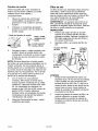
TERMINOLOG[A DE LA LAVADORA
A PRESI(_)N
psi: (Pounds per Square Inch) Libras por
pulgada cuadrada. Es la unidad de medida
pars la presi6n delagua. Tambien usada
pars la presi6n del sire, presion hidraulica,
etc
GPM: (Gallons per Minute). Galones por
minuto. Es la unidad de medida pars el
flujo promedio delagua a trav_s de la
lavadora a presi6n
REGULACI(_N
DE LA PRESI(_N
Los valores de calibrado de la presi6n
vienen regulados de fabrica, con el objeto
de Iograr la presi6n optima para la limpieza.
Si usted necesitase reducir la presion, ello
podr& Iograrse merced a los siguientes
metodos:
1.
CU: (Cleaning Units) Unidades de
limpieza. GPM multiplicadss por psi.
Retirese de la superficie que ha de
limpiarse. Cuanto mas alejado usted se
encuentre de la misma, menor presion
habra sobre la superficie que deber_
Iirnpiar.
2.
Modo de derivaci6n: Trabajando en modo
de darivaci6n, la bomba esta recirculando
el agua debido a que el gatillo de la pistola
rociadora no se encuentra presionado. Si la
unidad queda en modo de derivaci6n por
m&s de dos (2) minutos, se elevara la
temperatura delagua a niveles que podrian
da_ar los componentes intemos de la
bomb& Cualquier dafio debido a dichas
causas no quedar& cubierto por la garantfa.
Rote la boquilla del extremo de la
varilla rociadora multirregulable, pars
ensanchar el abanico de rociado
El
rociado mas ancho minimizar& la
presion sobre la superficie que ha de
ser limpiad&
NO intente
incrementar la
presi6n de la bomba. Un calibrado
superior al que trae de fabrics puede
da_ar la bomba.
NO
PERMITA
que
su unidad
funcione
en modo de derivaeibn (bypass) pot mas
de dos minutos en cualquier
cirsunstencia. El reealentamiento
le
ocasionsra da_os a Is bomba.
Valvula t_rmica de seguridad: Pars
prevenir dafios extremos, las bombas
est&q equipadas con una v&lvula termica
de seguridad. Dicha v&lvula se abrira
cuando la temparatura interior de la bomba
se eleve demasiado.Esta v_Jvula libarara un
chorro de agua, pars reducir la temparatura
interior de la bomb& Inmediatamente
despues que esto ocarra la valvula se
cerrar& La v&lvula termica de seguridad es
parte de la bombay no st& vi ibl pars el
usuario.
Sistema de inyeccibn de productos
quimieos: Mezcla los productos
limpiadores o los solventes de Iimpieza con
el agua, para mejorar la efectividad de la
limpieza.
Suministto de agua: Todas Iss lavadoras a
presi6n deben tener un suministro de agua.
Los requerimientos minimos pars el
suministro delagua son 20 psi y 22,7 litros
(5 galones) par minuto.
COMO
C(_MO
UTILIZAR
LA VARILLA
ROCIADORA:
Su lavadora a presion esta equipada con
una varilla rociadora muttirregulable para
calibrados de baja y alta presi6n. El
calibrado de alta presi6n es para Iimpieza y
enjuague, mientras que el de baja presi6n
es pars la aplicaci6n de productos
quimicos o soluciones de limpieza pars las
superficies.
_1'_
AI utilizar el ealibrsdo de
ere presiba, NO permita
que el chorro de rociado tome contacto
con la piel desprotegida,
ojos ni
cualquier mascota o animales. EIIo
podria ser Is eausa de seriss lesiones.
Riesgo de inyeccibn o lesibn a las
personas; NO dirija el chorro de
descarga hacia persona alguna.
Paraun funcionamiento
en alta presi6n, tire
hacia atras la boquilla de la varilla rociadora
multirregulable tal como se muestra.
USAR
IMPORTANTE:
Lea y comprenda cbmo
ussr Is presibn de la lavadora antes de
operarla.
45- SP
D28234
La boquJlfa del axtremo de la varilla
rociadora multirragulable puede rotarse
para cambiar el formato del rociado de alto
presi6n, desde una forma de chorro
angosto hasta un abanico de rociado de
40 °, tal como eat& mostrado. Se han
colocado marcas an la boquilla para
favoreeer la selecci6n dal formato de
rociado.
2.
Coloque el otto exttemo de Pa
manguera de productos quimicos con
su filtro instalado, dentro dal contanedor
del prodeato quimico o soluciSn de
ttmpbza. NOTA: La proporci6n de
produoto quimico / agua as 7:1, o sea,
pot coda 7 galonas (26,5 litros) de agua
bombeada ea usar& un gal6n (3,76 litros)
_e producto qdmico / so/uci6n
limpiadcra,
3.
Regule la boquiUa murdtregulable en la
posicion de presi6n m&s baja. Lea el
p&rrafo "Uso de la varilla rociadora", an
esta secci6n.
4.
Luego de usar productos qulmicoa,
cobque la manguera dentro de un
recipiente con agua limpia y
sueaionela a trav_s del sistema de
inyeccion quimica, a fin de enjuagar el
sistema completamente.
Si los
productos quimicos permaneciesen en
la bomba, esta podria resultar daSada.
Los da6os a las bornbas ocasionados
por productos quimicos no eaton
oubiertos por la garantia+
NOTAI Los produ_ea quimicos y jal::_n no
ser_ succionados cuando la vari_a rociado_a
est_ regulada an la posicion de alta presi6n.
Para una operani6n a baja presi6n,
extienda la boquilla de la varilla rocladora
multirregulable tal como se muestra.
PROCEDIMIENTO
IMPORTANTE:
DE APAGADO
Lea y oomprenda
cbmo
cortar la presi6n de la lavadora, antes de
operat.
C(_MO EMPLEAR
PRODUCTOS
QUIMICOS
Y SOLVENTES
PARA
LIMPIEZA
1.
El em_eo de prod_ctos quimicos o eafventea
para limpieza es eaa operaci6n de baja
presion. NOTk Utilice solamante jabones y
productos quimieas dise_adea para el uso en
favadorasa pred.. No use blanq_adorea
(lejla).
2.
Si ha sifonado productos quimicos,
repita la operaci6n con un balde de
agua lirnpia a traves de la manguera
qufmica. NOTA: no hacerb caeaar_,
dafio a la bomba.
Detanga el motor colocando el control
de aealeraci6n an la posici6n OFF.
Empleo de productoa qu|micos:
NOTA: NUNCA corte el suministro
agua con el motor en marcha.
1.
3.
Presione la rnanguera de productos
qufmicoa dentro del acople dentsdo
ubicado cerca de la conexi6n de la
manguera de alto presi6n de la bomba
tal como eat& meatrado+
D28234
CoIoque la vaNula de combustible en
la peaici6n OFF, si el motor no ha de
ponerse en marcha an breve.
4.
Corte el suministro
5.
Presione el gatillo de la pistola
rociadora a fin de aliviar cualquier
presi6n de agua dentro de la
manguera o la pistola rociadora.
6.
Vet la secci6n de Almacenaje de
_ste manual para el adacuado
procedimiento de almacenaje,
46_ SP
del
del agua.
ANTES DE COMENZAR
Lea y comptenda todas las insttucciones
importantes que se encuentran al
comienzo de este manual y a las
sigulentes precauciones y advertencias,
antes de dar arranque a la levadora a
presibn.
3,
JAMAS Ilene el tanque de
combustible completamente.
Complete el tanque dejando libre
12,7 mm (1/2") pot debajo del fondo
del cuelle de recarga, a fin de
proveer espacio pare la expansibn
del combustible. Umpie cualquier
derramamiento de combustible
del
motor y del equipo, antes de poner el
motor en marcha.
NO DEJE que les mangueras tomen
contacto con el sUenciador
extremadamente caliente del motor,
durante o inmediatamente
despu_s
del uso de su levadora a presibn. El
da_o ales mangueras proveniente
de su contacto con superficies
calientes NO SERA cubierto por la
garantia.
Verifique que la membrana del filtro
este en la entrada de agua de la
bomba, ta] coma se muestra. NOTA:
La cara del cono orientada hacia
fuera.
Membrana
del filtio
4.
Coaecte la manguera de alta presion a
la salida de la bomba.
5.
Conecte el sumiaistro
entrada de la bomba.
de agua a la
NOTA: El agua debe set suministrada a
an promedio de 22.7 litros (5 galones)
por minuto a 20 p.s.i.
JAMAS catgue el tanque de
combustible mlembas el motor est_ en
marcha o caliente. No fume mienb-as
estd Ilenando el tanque de combustible.
JAMAS clerre el paso del suministro del
agua mientras est_ en marcha el motor,
ello da6ard le bomba.
NO UTIUCE agua caliente; solamente
use agua frla.
NO interrumpa el rociado de agua pot
mbs de des minutos pot vez.
1.
2.
En una zona bien ventilada externa,
agregue gasoliaa nueva y de alta
calidad, sin plemo, identificada en el
surtidor de combustible con 86 o mas
octanos. No Ilene en exceso. Limpie
cualquier derramamiento de
combustible del motor y del equipo,
antes de porter el motor en marcha<
Para informarse del correcto
procedimiento, refi6rase al manual del
motor.
6.
Si intenta aplicar una solucion quimica o
de limpieza, sirvase leer "Coma succionar
productos quimicos/solventes
limpiadores", en la secci6n "lnstrucciones
de funcionamiento", de este manual.
7.
Abra el paso de alimentaci6n del agua.
NOTA: Dejar de hacerle podrla
causar dafio ale bomba.
Extraiga la tapa / varilla medidora y
agregue aceite al motor (suministrado)<
NOTA: El motor contendr& una ligera
cantidad de aceite, correspondiente a
las pruebas de fabrica.
47+ SP
D28234
8
Coloque la v&lvula de combustible en la
posicion ON, girandola 1/4 de vuelta en
sentido antihorario,
9
Mueva la palanca de control de
cebado a la posicion CHOKE ON,
N
y la del control de aceleraciSn a la
posicion FAST. _
NOTA: No se
requiere cebado para el arranque
cuando el motor est& caliente.
Si el motor no
arrancase luego
del segundo intento, presione el gatillo
para aliviar la presibn.
11. Si el cebador hubiese sido utilizado
para la puesta en marcha del motor,
mueva la palanca del cebador a la
posicion OFR
12.
Presione el gatillo de la pistola para
iniciar el flujo del aga&NOTA: Parese
sobre una superficie estable y
sostenga firmemente el mango de la
pistola/varilla rociadora con ambas
manos. Prevea el retroceso de la
pistola cuando _sta sea gatillad&
13.
Suelte el gatillo para detener dicho
flujo de agua.
14.
Regule la boquilla rociadora para la
tarea que piensa efectuar. Lea las
instrucciones en "Uso de la varilla
rociadora", de _sta secci6n.
de combustible
10.
Tire lentamente de la manija de
arranque hasta percibir resistencia,
luego tire firmemente. AcompaSe
suavemente el retroceso de la manija
de arranque. Tire de la soga con an
rapido y completo movimiento del
brazo. Deje que la soga se rebobine
lentamente. Repita si fuese necesario.
NO DEJE que las
mangueras tomen
contacto con el silenciador
extremadamente
caliente del motor,
durante o inmediatamente
despuds del
uso de su lavadora a presibn. El da_o a
las mangueras proveniente de su
contacto con superficies calientes NO
SERA cubierfo pot la garantia.
li_I-__i i _ _I li_I I_ _i i_o]
AL
HACER MANTENIMIENTO,
QUEDADEEXPUESTO
A LAS
SUPERFICIES
CAMENTES, PRESI()N
AGUA, MOVIMIENTO
DE
PIEZAS, O FUEGO CAUSANTE DE MUERTE. ANTES DE REAUZAR CUALQUIER
MANTENIMIENTO
O REPARACION, DESCONECTE EL CABLE DE BUJiA, PERMITA
ENFRIAR AL MOTOR Y LtBERE TODA LA PRESION DEL AGUA. EL MOTOR CONTIENE
COMBUSTIBLE
INFLAMABLE. NO FUME O TRABAJE CERCA DE LLAMA ABIERTA
MIENTRAS DESARROLLA EL MANTENIMIENTO.
Para asegurar una eficiente operacion y larga vida de su lavadora a presion, se deberia
programar y seguir una rutina de mantenimiento. Si la lavadora a presion se usa en
condiciones inusuales, tales como alta temperatura o polvo, se requiere un mantenimiento
mas frecuente.
D28234
48- SP
TABLA
DE RESPONSABIUDADES
TAREA
DE
MANTENIMIENTO
DEL CMENTE
Antes de
cads uso
Cada 25
horas o
anualmente
Cada 50
horas o
anualmenk
Cada 100
horas o
anualmente
MOTOR
Verifique el nivel de aceite
X
Cambie el aceite
X
Verifique el filtro de aire
X
X
Limpie / reemplace la bujia
LAVADORA
A PRESI(_N
Verifique / limpie la rejilla de entrada
X
inspeccione
presion
X
la manguera de alta
inspeccione la manguera del jabSn,
productos quimicos y el filtro
X
Verifique la existencia de perdidas
sobre la pistola y la varilla
X
preparaci6n
para el almacenaje
Prepare la unidad para su almacenaje si es que la misma
permanecer& inactiva por rods de 30 dias.
MOTOR
Verificacibn
1
,,
_
del aceite
Detenga el motor y coloquelo
una superficie nivelada.
sobre
Tapa / varilla
medidora del
Limite superior
_LiLmi_t!
ceite
inferior
4.
Si el nivel de ace_e es bajo, I_o
hasta el borde del orificio de Ilenado de
aceite, utitizando aceite SAE 10W-30.
Nora: pueden utilizarse otras viscosidades
mostradas en el grafico, cuando el
promedio de temperatura de su zona se
encuentre dentro del rango recomendado.
3radosde visc0sidadrecomendad0s
2=
Extraiga la tapa / varilla medidora del
aceite, y limpiela.
3.
Coloque y extraiga la tapa / varilla
medidora del aceite sin roscarla en el
cuello de Ilenado. Verffique el nivel de
aceite mostrado sobre la varilla
medidora.
F-20
0
20
32 40
60
80
t00
•' -2_ -10
...........
3-30
0
10
20 30 40
RANGO
DETEMPERATURA
DECOMIENZO
ANTiCiPADO
ANTESDELPRXIMOCAMBIO
DEACEITE
49- SP
D28234
Cambio
Filtro de aire
de aceite
Drene el aceite del motor mientras el
mismo se encuentre caliente. El aceite
caliente drena mas rapida y
Un filtro de aire sucio restdngira el flujo del aire al
caCeuradory set& la causa de una eficiencia
pobre del motor. Inspeccione el filtro csda vez
que se ponga el motor en march& Limpie el fittro
con mayor frecuencia si el motor debe set
operado en zonas muy polvorientas.
completamente.
1.
2.
Mueva la valvula de control del
combustible a la posicion OFF,
girandola 1/4 de vuelta en sentido
horario.
ADVERTENOIA: La operaei6n de! motor sin un
filtro, pen_itir& la entrada de suciedad al motor,
causando el desgaste rapido del mismo. Este tips
de da_o no queda cubierto per la garentia.
INSPECCI(_N
Coloque un recipiente apropiado
pr6ximo al motor a fin de recibir el
aceite usado.
Cuello de llenado
1.
Presione las orejas de traba en la parte
superior de la cubierta del filtro de aire y
extraiga Is cubierta. Vedfique el estado del
filtro para asegurarse de que este limpio y
en buenas condiciones.
2.
ReinstaJeel filtre y Ia cubierta del filtro de
aire.
de aceite
Tape / varilla
aceite
Ii_m
3.
Limite
iedidora
superior
del
ite inferior
Cuerpo
de aire
Extraiga la tapa / varilla medidora del
aceite y drene el aceite dentro del
contenedor, inclinando el motor hacia
el lade en que se encuentra el cuello
de Ilenado.
del filtro
Fittro
Cubierta
NOT/_ Sirvase desechar el aceite usado
del motor de una manera compatible con el
medio ambiente. Se recomienda Ilevar el
aceite usado en un contenedor hermetico a
de aire
su centre local de reciclaje o la estaci6n de
servicio para su recuperaci6n, No Io arroje
a la basura ni Io vierta sobre la tierra ni a
traves de la tuberia del desagL_e.
4.
5.
Con el motor ea una posicion
nivelada, Ilene hasta el limite de la
marca superior mostrada en la varilla
medidora, utilizando aceite SAE 10W30. La capacidad de admision de
aceite es de 0,55 litro (0.58 cuarto de
gal6n) NOTA: Podr_ utilizarse
tambiea otras viscosidades de aceite,
mostradas en el p_rafo del grafico
_Verificaci6n del aceite%
Limpieza
1,
Golpeeel filtrorepetida_T_ntesobre una
superficie dura a fin de remover la suciedad,
o bien sopletee con aire comprimido (sin
exceder tas 30 psi (207 kPA, ! ,2 Kg/cm 2)a
traves del filtro, desde el lade timpio que se
orienta hacia el motor. Jamas intente de
cepitlar la suciedad. El cepittado introducira
la suciedad en Iss fibras.
2,
Reponga firmemente la tapa / varilla
medidora del aceite.
D28234
50* SP
Limpie ta suciedad del cuerpo del filtre y la
cubierta, ufilizando un genero h0medo.
Tenga cuidado en prevenir la entrada de
suciedad al conducto de aire que conduce
al carburador.
Limpieza
y reemplazo
3
de las bujfas
Cambie las bujias cada 100 horas de
operacion o una vez al a£+o,Io que ocurra
primero. Ello ayudarA a su motor a facilitar
su arranque y funcionar major.
4<
5.
Apriete el gatillo del mango de la
pistola para aliviar la presiSn del agua
Desconecte ]a variila rociadora de ]a
pistol&
Remueva la boquilla del extremo de la
varilla con una Ilave Allen de 2 ram+
provista, tal como se muestra.
Medida de alambre
6
Lfmpie la boquilla usando el limpiador
provisto para boquilla o un clip de
papeles enderezado+ Insertelo dentro
del extremo de la boquilla y muevalo
hacia adelante y atr_s hasta qua la
obstrucci6n sea removida+
7.
Enjuague el extremo de la boquilla con
agua del suministro normal durante 30
segundos para desprender particulas
sueltas.
8
9
Reconecte el cable de la bujfa+
Rearme la boquilla en la varilla
rociadora+ Ajt_stela firmemente para
prevenir p_rdidas+
Reconecte la varilla rociadora a la
pistola y abra el paso del agaa+
Ponga an marcha la lavadora a
presion y coloqae la varilla rociadora
en su m_txima presi6n para verificarla.
Resistor
BOMBA
Esta membrana de filtracion debe sat
verificada peri6dicamente y Iimpiada si
fuera necesario.
1.
Quite la membrana de filtrado
tomandola firmemente pot su extremo
y removi_ndola de la entrada del agua
a ia bomba tal como se muestra+
2.
Limpie el filtro enjuagAndolo
en ambos lados+
3.
Reinserte el filtro en la entrada de
agua de la bomb& NOTA: La cara del
cono orientada hacia fuera.
con agua
NOTA: No haga funcionar la lavadora a
presiSn sin el filtro adecuadamente
instalado.
Membrana
de filtrado
10.
11.
VARILLA ROCIADORA
Si la boquilla comienza a obturarsa con
materiales extraSos, tales como la tierra
paede generar excesiva presiSn+ Si
comienza a obturarsa parcialmente o as
restringida, la presion de la bomba
comezar_ a pulsar. Lfmpie la boquilla
inmediatamente asando el jaego provisto
y las siguientes instrucciones:
1.
Apague la lavadora a presidn y corte
el suministro de agua.
2,
Desconecte el cable de la bujia para
asegurarsa de qua la unidad no
podra arrancar mientras se efectOe el
mantenimiento+
51 * SP
D28234
MOTOR
BOMBA
IMPORTANTE: Es importante prevenir la
formaci6n del dep6sito de gomas en partes
esenciales del sistema de combustible, tales
como el carburador, el filtro de combustible,
manguera o el tanque durante el periodo de
almacenaje. Asimismo, la experiencia indica
que los combustible con alcohol (llamados
gasohol o los que usan etanol o metanol)
pueden atraer humedad, Io cual conduce a la
separaci6n y formacion de &cidos durante el
almacenaje. La acidez del gas puede daSar el
sistema de combustible de un motor mientras
este se encuentra almacenado. Para evitar
problemas al motor, el sistema de combustible
debe set vaciado ante de su aImacenaje por
periodos de 30 dias o mayores. Jam&s use
productos limpiadores del motor o el
carburador en el tanque de combustible,
porque podrian ocurrir daSos permanentes.
1.
Drene toda el agua de la manguera de
alta presi6n, enr611ela y gu&rdela en el
soporte del maaillar de la lavadora a
presion.
2.
Dreae toda el agua de la pistola
rociadora y de la varilla rociadora
sosteniendo la pistola rociadora en
posici6n vertical, con el extremo de la
boquilla apuntando hacia abajo y
presionando el gatillo. Almacene la
pistola y manguera en el soporte del
manillar de la lavadora a presi6n.
3.
Guarde la manguera de productos
quimicos, la manguera de alta presi6n,
la pistola rociadora y la varilla
rociadora de forma tal que queden
protegidas de ser dafiadas, tales como
ser pisoteadas.
Se recomienda que siga usted estos pasos
para la proteccidn de los sellos interiores de
la lavadora a presi6n CUANDO LA UNIDAD
SEA ALMACENADA POR M/kS DE 30 DiPS
Y/O CUANDO SE ESPEREN.
Preparacibn
del motor
Primeramente agregue estabilizador de
combustible al tanque.
Haga funcionar la lavadora a presi6n
durante 5 minutos a fin de permitir la
entrada del estabilizador a todo el
sistema de combustible.
*RV debera ser fluido a trav{_s de la bomba
a
motor, asegt_rese de que el saministro del
agua se encuentre abierto y que se
encuentre fluyendo hacia la unidad. JAM_.S
opere la unidad sin el suministro de agua
funcionando a traves de la bomba. La
desatenci6n de hacedo causarb da_os a la
bomba
Lo siguiente sera detener el motor y
desconectar el suministro del agua.
tal como se menciona en los pasos
siguientes.
4.
Obtenga un embudo, 0,178 litros de
anticongelante *RV y aproximadamente
- 91,5 cm (36
pulgadas) de manguera de jardin, con
un conector macho en un extremo.
Use solamente
anticongelante RV.
Cualquier otto anticongelante
resulta
corrosivo y puede da_ar la bomba.
5.
Desconecte el cable de la bujia.
Desconecte el cable de la bujia y
extraiga a esta.
Agregue una cucharadita de t_ con
aceite a traves del orificio de la bujia.
Coloque un trapo encima del orificio de
la bujia y tire del arranque un par de
veces a fin de lubricar la camara de
combusti6n.
Reponga la bujia, pero no conecte su
cable.
6.
D28234
52" SP
Conecte la manguera de 91,5 cm (36
pulgadas) a la entrada de agua de la
bomba.
7
8.
Agregue anticongelante *RV a la
manguera tal como se muestra.
Tire varias veces lentamente de la
10.
Reconecte
el cable de la bujla.
*Tambi_n puede utilizarse el fluido
lavaparabrisas.
soga de arranque hasta que el
anticongelante salga pot la conexi6n
de la manguera de alta presi6n en la
bomb&
9.
Extraiga la manguera corta de la
entrada de agua de la bomb&
[_tllj_ la]_ Ia]V.,%_]_']lli[_e]
no
8,1"l"8,rtc a
Y.,%.
_]
CORRECCl0N
CAUSA
PROBLEMA
El motor
la]_ I'.]-'[e]_]!_
1.
Sin combustible.
Agregue combustible.
2.
Acumul&ci6n de presion
despues de tirar dos veces
de la cuerda del arrancador o
despues del primer uso.
Apriete el gatillo de la pistola
pare aliviar la presi6n.
3.
La leva de cebado (choke)
est& en la posicion de "No
Choke".
Mueva la leva de cebado a la
4.
Cable de la bujia sin
conectar.
Conecte el cable de la bujfa.
5.
La leva de cebado (choke)
Mover la leva de cebado
est& en la posicion de
"Choke" cuando el motor
est& "caliente" o cuando ha
estado expuesto al calor pot
un largo periodo.
(choke) a la posicion de "No
Choke".
6.
V&lvula de paso de
combustible cerrada.
Mover la leva de la v&lvula de
combustible a la posici6n
1.
La varilla rociadora no esta
en alta presi6n.
1.
En la secci6n Instrucciones de
funcionamiento, vea el parrafo:
Uso de la la varilla rociadora.
2.
Poco suministro
2.
El suministro de agua debe ser,
pot Io menos, 5 GPM a 20 psi.
P6rdida en la conexi6n de la
manguera de alta presi6n.
3.
Repare la perdida. Aplique cinta
selladora si fuera necesario.
Boquilla obstruid&
4.
Pare informarse del
posici6n de "Choke".
"Open" {Abierto).
Nada o b_a
presidn
_espu_sdel
usoinicial)
de agua.
procedimiento correcto, lea el
p&rrafo referente a la varilla de
rociado dentro de la seccion
Mantenimiento.
Membrana atascada del filtro
5.
Remueva y limpie el filtro.
de agua.
53_ SP
D28234
PROBLEMA
Nada o baja
presibn
(despuds del
uso inicial -
CAUSA
CORRECCION
6.
Aire en la manguera.
6
Apagar el motor y luego cortar el
suministro de agua Desconectar
el suministro de agua de la
entrada a la bombay abrir el
suministro de agua para eliminar
todo el elre que haya en la
manguera. Cuando se obtenga
un flujo de agua constante, cerrar
el suministro de agua.
Reconectar el suministro de agua
a la entrada de la bomba y ebrir
el suministro de agua. Apr_ar el
gatillo para eliminar el aire
restante.
7.
La leva de cebado (choke)
est& en la posicion de
"Choke".
7.
Mover la leva a la posici6n de
"No Choke".
8<
La leva del control de
aceleracion no est& en la
continuacibn)
posicion
No succiona
"Fast" (R_pido).
9.
La manguera de alta presi6n
es demasiado larga<
1.
La varilla roeladora no est&
productoe
quimicos
Mover la leva del control de
aceleracion
(R&pido).
Utilice manguera de alta preel6n
para distancias menores a 100
pies (30,5 m)
1.
En ]a secelon Instrucelones de
funcionamiento, vea el p&rrafo:
uso de la varilla rociadora.
2.
Lfmpie el filtro.
en baja presion.
2.
3.
4.
Filtro obstruido
de
productos quimicos.
La mella de productos
quimicos no est& dentro
del producto quimico.
El producto quimico est&
demasiado espeso.
AsegQrese que el terminal de la
manguera de productos
qufmicos est_ completamente
sumergido.
Diluir mas el producto quimico.
El mismo debe tener la misma
consistenela
del agua.
5.
La manguera de elta presion
es demasiado larga.
Alargue la manguera de
suministro de agua antes que la
manguera de alta presi6n<
6.
Acumulaci6n
Hacer limpiar las piezas o
reemplazarlas por AWSC.
de sedimentos
quimicos dentro del
inyector.
D28234
a la posicion "Fast"
54" SP
PROBLEMA
Nada o baja
presibn
(despu_s de un
periodo normal
de uso)
CAUSA
Sello gastado o
empaquetadura
atascada.
Valvulas gastadas u
obstruidas.
1.
Reemplacelas
por AWSC.
2.
Reemplacelas
por AWSC.
3.
Pist6n de descarga gastado.
3.
Reemplacelas
por AWSC.
1.
O-ring gastado o roto.
1.
Verificar y reemplazar.
2.
Acople de manguera flojo.
2.
Ajustar.
Agua goteando
1.
Acoples flojos.
1.
Ajustar.
de la bomba
2.
Empaquetaduras
piston ...
3,
O-rings gastados o rotos.
3.
Reemplacelas por AWSC.
4.
Csbezal de la bombs o tubos
4.
Reemplacelas
1.
Pars informarse del
procedimiento correcto, lea el
p&rrafo referente a la varilla de
rociado dentro de la seccion
Mantenimiento.
Agua goteando
en la conexibn
de la
pistola/varilla
rociadora
1.
CORRECCI(_N
2.
da_ados
La bomba
pulsa
1.
gastadas d_ 2.
Reemplacelas por AWSC.
por AWSC.
pot con gelamiento.
Boquilla obstruida.
55- SP
D28234
Get it fixed, at your home or ours!
Your Home
For repair - in your home - of all major brand apphances,
lawn and garden equipment, or heating and coohng systems,
no matter who made it, no matter who sold it!
For the replacement parts, accessories and
owner's manuals that you need to do-it-yourself.
For Sears professional installation of home apphances
and _tems hke garage door openers and water heaters.
®
1-800-4-MY-HOME
(1-800-469-4663)
www.sears corn
Anyttme, day or night
(U S A and Canada)
www.sears.ca
Our Home
For repa=r of carry-=n products hke vacuums, lawn equ=pment,
and electron=cs, call or go on-hne for the nearest
Sears Parts and Repair Center.
1-800-488-1222
Anytime,
day or
night
(U S A
only)
www sears.com
To purchase a protect=onagreement on a product serv=cedby Sears.
1-800-827-6655
(u s A)
1-800-361-6665
Para ped_rserv_o de reparac_on
a doml_l,o, y para ordenar ptezas.
1-888-SU-HOGAR s_
(1-888-784_427_
(Canada)
Au Canada pour serv_e en fran_;a_s
1-800-LE-FOYER Mc
(1-800-533-6937)
WWW S_aFS
ca
SE -/AtlR,_
©Sears RoebL_k a_'/JCo
® Regis[er=d
Trademark
®MarcaRegLstrada'
r,lc Marque
de commerc_
/ TT
* Trademark
i T
_ MarcadeFabrica/
r,l¢.Marque
sr,_ Service
Mark of Sears
5r
_MarcadeServkcLodeSears,
deposee
de Sears,
Roebuck
Roebuck
and
Roebuck
and
Co
Co
and Co