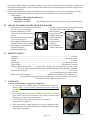
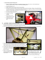
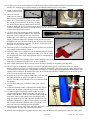
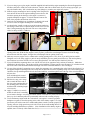
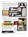
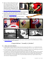
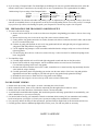
1
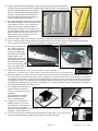
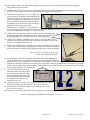
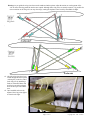
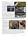
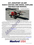
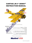
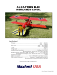
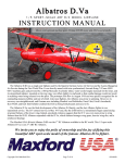
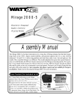
1/5 NIEUPORT 28 ARF RADIO CONTROL WWI MODEL AIRPLANE INSTRUCTION MANUAL NOTE: Shown with windshield, WWI pilot figure, scale machine guns, motor and propeller. These optional items are not included with the ARF. Congratulations on your acquisition of Maxford USA’s Nieuport 28 ARF! The Nieuport 28 was a French biplane fighter flown during World War I, designed by Gustave Delage and built by Nieuport, also known as Nieuport-Delage – a French airplane company famous for racers before World War I and fighter aircraft during World War I and between the wars. Retaining many of the Nieuport 17‟s best features, the Nieuport 28 was a lightly built, highly maneuverable fighter: It had a more powerful engine; carried twin synchronized machine guns; its ailerons were fitted only to the lower wing; and it had twospar wings – top and bottom – in place of the earlier Nieuport types‟ sesquiplane (a biplane with one long wing and one short one above or below it). The Nieuport 28 was the first aircraft to see service in any American fighter squadron. By the time the Nieuport 28 became available in early 1918, it was already considered “surplus” from the French point of view. Their SPAD XIII was a superior aircraft in most respects and had already become firmly established as the standard French fighter. (A 1/5-scale ARF SPAD XIII is also available from Maxford USA at www.maxfordusa.com.) When the Nieuport 28 was offered to the United States, it was immediately accepted by the American Expeditionary Force, and 297 Nieuport 28s were put into service in the 27th, 94th, 95th and 103rd Aero Pursuit Squadrons. Several well-known WWI American pilots, including 26-victory American ace Captain Eddie Rickenbacker and Lieutenant Quentin Roosevelt – the youngest son of former President Theodore Roosevelt – flew Nieuport 28s. Sadly, on July 14, 1918, just 4 months before his 21st birthday, Lieutenant Roosevelt‟s Nieuport 28 was downed behind enemy lines, felled by two machine gun bullets which struck him in the head. His body was buried at the crash site by the Germans. Twenty-six years later, following the World War II D-Day invasion of France, Quentin's brother, Brig. Gen. Theodore Roosevelt, Jr. died of a heart attack on July 12, 1944 and was buried at the Omaha Beach War Memorial. Quentin‟s remains were then reinterred beside his elder brother. This model of the Nieuport 28 is a new design with improvements over previous products. It is constructed mainly of laser-cut balsa and light ply, finished with a Mylar film covering patterned after the aircraft flown by 94th Aero Squadron‟s ace pilot Eddie Rickenbacker, and may be special-ordered with the option of a flat-finish or as a fabric-covered prepainted ARF. We invite you to enjoy the pride of ownership and the joy of flying your highquality balsa and light-ply almost-ready-to-fly version of this historic aircraft. Entire contents – Copyright 2015 Page 1 of 17 Copyright 2015 - N28 / S150326 TABLE OF CONTENTS I. Important safety precautions & assembly tips .... 2 II. Warranty, liability waiver, and return policy ..... 3 III. Special features of this Nieuport 28 model ........ 4 IV. Specifications ..................................................... 4 V. Parts List ............................................................. 4 VI. Assembly photo-instructions ......................... 5 VII. Setup and adjustments ................................. 15 VIII. Preparation for transport and field setup ..... 16 IX. Preflight checks ........................................... 16 I. SAFETY PRECAUTIONS & ASSEMBLY TIPS: (IMPORTANT – READ THIS SECTION BEFORE YOU BEGIN ASSEMBLY) 1. This product should not be considered a toy, but rather a sophisticated, working model that functions much like a full-scale airplane. Because of its performance capabilities, this product, if not assembled and operated correctly, could cause injury to you or spectators and damage to property. Maxford USA provides you with a high-quality, thoroughly tested model airplane kit with assembly instructions. However, the quality and capabilities of your finished model airplane depend on how you assemble it, and your safety depends on how you use and fly it. Any testing or flying of this model airplane is done entirely at your own risk. 2. Assemble this model airplane according to these instructions. Do not alter or modify the model beyond the assembly and power system options covered in these instructions, as doing so may result in an unsafe or unworkable model. In a few cases the instructions may differ slightly from the photos; in those instances the written instructions should be considered as correct. If you have a question or concern about these instructions, before you proceed with assembly of this product, contact your dealer or speak to a Maxford USA customer service representative at 562-529-3988 (Monday through Friday, except national holidays, 9 AM to 5 PM Pacific time). 3. While this kit has been flight-tested to meet or exceed our rigid performance and reliability standards in normal use, if you elect to perform any extremely high-stress flying, such as racing or advanced aerobatics, or if you install a larger power system than specified, you (the buyer or user of this product) are solely responsible for taking any and all necessary steps to reinforce the high-stress points and/or substitute hardware that is more suitable for such increased stresses. 4. Throughout the lifetime of this model, use only the Maxford USA-recommended or same-sized engine or motor and a new or well-maintained radio control system and batteries recommended by the maker of your motor and radio system. 5. It is your responsibility to install the R/C system and other components in such a way that this model airplane passes all applicable safety/range tests and that the power system and controls operate correctly and smoothly. 6. Recheck the operation of this model airplane before every flight to ensure that all equipment is still operating correctly and that the model has remained structurally sound. Also before every flight, check all electrical and structural connections; do not fly without properly connecting or replacing any that you find poorly connected, damaged or worn. 7. Before you begin assembly of this model airplane, read all instructions and test-fit each part to ensure you fully understand the instructions and that no parts are missing, damaged or unsatisfactory. Temperature and/or humidity differences between the factory, our warehouse and your home or workshop may dictate the need for slight adjustments to the wings, struts and/or the vertical or horizontal stabilizer‟s mounting surfaces to ensure proper alignment; however, we recommend you contact us before you attempt any such adjustment(s). 8. To help ensure the security of any in-line servo-type connections, optional Maxford USA servo-extension safety clips are recommended. 9. Assemble EZ-Link connectors (which may be included or an option for this model). As shown at the right, when Clamping bolt applying threadlock compount or CA adhesive, Connector body be careful to NOT glue the EZ-Link connector to the Control arm (or mounting tab) control arm or mounting tab; also be careful to not Washer let the pushrod rub or bind against nearby surfaces. Mounting nut 10. As shown at the right, this model allows customers some choice in aileron servo selection: a. Test-fit your aileron servos and the supplied wood mounting pedestals to the servo hatch covers. b. Use epoxy to attach the mounting pedestals to each servo hatch cover. Use the hardware provided with your servos to mount the aileron servos to their hatch covers. c. Using your radio or a servo tester, center the aileron servos. (You may be interested to learn more about servo testers at http://www.maxfordusa.com/servo.aspx.) Page 2 of 17 Copyright 2015 - N28 / S150326 11. 12. 13. 14. 15. 16. 17. 18. 19. 20. 21. 22. d. String may be supplied to pull your servo‟s lead and servo extension through the wing to your radio receiver; however, you may find it easier to use masking tape to temporarily attach the connector to the end of a length of coat-hanger wire, then use the wire to pull the lead and connector through the airframe as shown at the right. e. Guide the servo into the servo bay, cover the servo bay with the servo-hatch and secure the hatch with screws or glue. After you have determined each servo-mounting-screw‟s location, apply thin CA adhesive to harden the wood where the servo‟s mounting screws will be inserted. If Mylar hides a CA hinge‟s slot, find and open the slot by carefully pressing with a fingernail or sharp hobby knife. Use the tip of a hot soldering iron to burn and remove any Mylar covering material to obtain good wood- to-wood gluing surfaces at the horizontal and vertical stabilizers. We recommend 30-minute epoxy for permanent attachment of critical parts such as where the horizontal and vertical stabilizers attach to the fuselage. If you have concern about the security of any factory fabrication procedure(s), we recommend you apply 30-minute epoxy around the perimeter of such part(s) as an extra safety precaution. We recommend use of a thread-locking compound to secure all hardware from vibration. Also, once the included clevises are adjusted, we suggest you coat each clevis and rod with epoxy to securely and safely affix each clevis to its rod. As a safety precaution, always check each clevis before and after each flight. This model includes some fiberglass or carbon-fiber reinforced parts. If you drill, grind or sand a fiberglass or carbon-fiber reinforced part, always wear safety goggles, a particle mask and rubber gloves to guard yourself from eye, skin and respiratory-tract irritation; never blow into the part to remove fiberglass or carbon fiber dust (the dust may blow back into your face). Check the Mylar covering material‟s joints and surfaces; if necessary, carefully use an iron (do NOT set the iron‟s temperature too high) to secure the edges and to tighten any loosened areas. Recheck and retighten from time to time. For your safety, do NOT leave any strands of wire poking out from the end of any crimp tube. Exposed small steel strands can be sharp enough to cut or abrade skin! Minor production details may vary. If you are not an experienced ARF assembler or R/C pilot or have not flown this type of model before, we strongly urge you to get assistance from an experienced ARF assembler or R/C pilot. Read all instructions included with your batteries and charger. Failure to follow all instructions could result in permanent damage to the battery, its surroundings, and bodily harm! If you crash this model airplane, check whether the batteries are damaged. Do NOT attempt to use or recharge a damaged battery. II. WARRANTY, LIABILITY WAIVER, AND RETURN POLICY Maxford USA guarantees this kit to be free from defects in material and workmanship at the time of purchase. All of our products have been inspected in our factory and are checked again when shipped from our warehouse. However, Maxford USA cannot directly control the materials you may use nor your final-assembly process. Therefore, Maxford USA can NOT in any way guarantee the performance of your finished model airplane. Furthermore, in purchasing this product, you (the buyer or user of this product) exempt, waive, and relieve Maxford USA from all current or future liability for any personal injury, property damage, or wrongful death, and if you (the buyer or user of this product) are involved in any claim or suit, you will not sue Maxford USA or any of its representatives. If you do not fully accept the above liability and waiver, you may request a return merchandise authorization number (RMA#) as explained in item 2, below. If you think there is a missing part or any shipping damage, please read our after-sales service and return policy as outlined below. 1. Inspect your order upon delivery for any shipping damage or missing part. If you find a problem you must contact us within 10 days from receipt of your purchase by calling (562) 529-3988, Monday through Friday, except holidays, between the hours of 8:30 AM and 5 PM Pacific time. During this telephone conversation, and with your support, we will determine how to resolve your concern. (Note: Maxford USA batteries are sold without warranty and are not eligible for return or credit.) 2. To request an RMA#, call (562) 529-3988, Monday through Friday, except holidays, between the hours of 8:30 AM to 5 PM Pacific time. If we elect to issue you an RMA#, you must clearly mark this RMA# on the outside of the package. (No return or exchange will be authorized after 10 days from the date of your receipt of the product; any package delivered to us without a Maxford USA RMA# is subject to being returned to the sender, as received, with return postage payable upon delivery.) Page 3 of 17 Copyright 2015 - N28 / S150326 Returned merchandise must be in its original condition as received from Maxford USA, with no assembly or modification, in the original packing materials, complete with all manuals and accessories. Return shipping and insurance charges must be prepaid by you, the buyer. 3. Returned merchandise that is accepted by Maxford USA for credit is subject to a 10% to 20% restocking fee (the final amount will be determined by Maxford USA upon receipt and examination of the returned merchandise). Return Address: Maxford USA RC Model Distribution, Inc. 15939 Illinois Avenue #C Paramount, CA 90723 (Print the RMA# issued by Maxford USA on the package near the address.) III. SPECIAL FEATURES OF THIS NIEUPORT 28 MODEL Wing panel sets are removable from the fuselage for ease of storage and transport. Prepainted fiberglass cowl with Max Cowling „invisible‟ attachment system. Each aileron is separately operated by its own in-wing servo. Precut dashboard openings for your ignition and radio switches. Wing support kit is included for safe transport and storage. Streamlined landing gear. Includes preinstalled cockpit coaming, dummy engine, fuel-system venturi and air intake tube. Pull-pull rudder. Stick-on decal set. Supplied machine gun mounting platforms. (Scale-looking machine guns are optional.) Photo-enhanced assembly instructions. IV. SPECIFICATIONS * Wingspan ................................................................................................................................ 68 inches Wing Area ................................................................................................................. 920 square inches Length ..................................................................................................................................... 56 inches ARF weight .................................................................................................... 10 pounds and 6 ounces Flying weight ................................................................................................. 11 pounds and 14 ounces Engine required (Not included) ...... 26cc gas, 90 to 120 glow or an equivalent electric power system such as the Uranus 638109 brushless motor and 100 Amp High Voltage Brushless Controller Propeller (Not included) ................................................................................................... 18 to 20 inch (as recommended for your power system) Radio system (Not included) ....................................... Minimum of 4 channels and 5 standard servos or 4 standard servos and an electronic speed control, if you use an electric power system * V. (All dimensions and weights are approximate.) PARTS LIST 1. Items you must supply to complete this Nieuport 28: 26cc gas engine, 90 to 120 glow engine, or an equivalent electric-powered motor. (See http://www.maxfordusa.com/brushlessmotorandcontroller.aspx for detailed information about Maxford USA electric power systems.) Propeller. Five(5) standard-sized servos [four(4) standard servos if you use an electric power system], two(2) 18-inch extensions, one(1) 6-inch Y-connector, and a minimum of a 4-channel radio control system. 5- and 30-minute epoxy or aliphatic resin glue, thin and thick Cyanoacrylate (CA) adhesives. Pliers, Allen wrenches, a high speed rotary tool, scissors and masking tape. Optional upgrade items: Scale machine guns; windshield; WWI pilot figure; and Scimitar-type propeller. Page 4 of 17 Copyright 2015 - N28 / S150326 2. Items included with this Nieuport 28: Precovered fuselage, upper and lower-wing panels and upper-wing‟s center section, vertical and horizontal stabilizers, rudder and elevator halves, with all hinge openings precut. Prepainted fiberglass cowl. Rudder pull-pull cables and aileron and elevator pushrods. Wing joiners, preformed cabanes and struts, and all required control horns, hinges, linkages, wing and tail flying wires and related hardware, including self-threading and machine screws and nuts (except those normally supplied with the servos and a glow or gas engine or electric power system). Fuel tank with clunk and fuel lines. NOTE: Shown with optional windshield, WWI pilot figure and scale machine guns. Streamlined landing gear with scale-like wheels. Complete set of scale markings. Magnetically secured cockpit hatch and coaming. Simulated fuel-system venturi and air intake tube. VI. ASSEMBLY PHOTO-INSTRUCTIONS 1. Pull the engine mounting box out of the nose and set it aside. (NOTE: If the engine mounting box seems „stuck‟ in the nose, carefully reach in through the cockpit and push it out from the inside.) 2. Position the fuselage onto its back and insert the landing gear‟s cross-struts into the slots in the fuselage as shown below. 3. Position the wooden landing gear retainer between the landing gear‟s rear struts, then press the rear strut and retainer into the fuselage until the outer edge of the retainer is flush with the bottom surface of the fuselage. 4. As shown at the right, secure the retainer with glue or with 2 bolts. 5. Test-fit the three metal landing gear retainers over the landing gear‟s front strut. 6. Drive 6 ea. bolts into the 6 ea. blind nuts inside the fuselage to secure the landing gear‟s front retainers. Page 5 of 17 NOTE: You have the choice of securing the rear landing gear struts’ retainer into the fuselage by driving bolts into the preinstalled blind nuts pictured above, or you may simply glue the retainer into its opening in the fuselage. Copyright 2015 - N28 / S150326 7. Using a total of 4 wheel collars, attach both main wheels to the landing gear‟s axles with wheel collars and secure with threadlock. 8. Test-fit the hatch: (1) Lift the rear of the hatch above the magnet and toward the rear; (2) Lift the front and maneuver the hatch‟s corners to clear the edge cockpit. (Note: You may remove a bit of wood from the hatch‟s front corners for added clearance.) 9. Slide the lower wing rod midway through the fuselage. (NOTE: Apply a small amount of light machine oil to the wing rods if necessary to help them slide.) 10. Temporarily position the lower left and right wing panels onto the lower wing rod. 1 (Note: As the lower wing panels near the fuselage, fit the lower wing panel‟s alignment pins into their openings in the fuselage as shown at the right.) 11. Cut away the Mylar covering the slotted opening in the horizontal stabilizer for the vertical stabizer and test-fit the vertical stabilizer to the horizontal stabilizer. 12. Test-fit the horiz. stabilizer to its platform at the top-rear of the fuselage. Remove the Mylar at the bottom of the horiz. stabizer to ensure a good wood-to-wood glueing surface between the horiz. stabilizer and the fuselage as pictured below. 2 13. As shown at the right, place flex-type drinking straws (not supplied) over both of the threaded ends of the elevator‟s pushrod. 14. Guide the pushrod into the nose and through the rectangular openings on each side of the fuselage as follows: a. Insert the pushrod and straws into the fuselage until the free ends of the straws are near the rectangular openings in the sides of the fuselage. (NOTE: You may slightly bend the 2 ends of this forked pushrod toward each other if necessary to more easily fit the forked pushrod and straws into and through the fuselage.) b. Guide the end of one straw out its nearest opening. c. Guide the end of the remaining straw out through the opening on the other side of the fuselage. Page 6 of 17 Copyright 2015 - N28 / S150326 d. While continuing to direct the pushrod toward the tail, guide the straws and prongs straight back at the same time. (NOTE: Do NOT attempt to pull the straws or the prongs outward, away from the PULL STRAIGHT BACKWARD fuselage.) (TOWARD THE TAIL) e. After the bent portion of each prong has passed fully through its rectangular opening, remove and set aside its straw. (NOTE: If you ever need to remove the elevator pushrod from the fuselage, we suggest you put straws back onto the pushrod‟s prongs and reverse the above procedure.) 15. Twist a clevis (pictured at the right) onto the threaded ends of each of the elevator pushrods. 16. Perform a final test-fit of the horizontal stabilizer to its platform at the top-rear of the fuselage. Ensure the horizontal stabilizer is parallel to the lower wing by visually comparing the horizontal stabilizer to the lower wing. 17. Use 30-minute epoxy to secure the horizontal stabilzer to the fusealge. Hold the horizontal stabilizer parallel to the wing with masking tape until the epoxy cures. 18. Test-fit the plastic tail-group cover at the rear of the fuselage‟s turtle deck and the top of the horizontal stabilizer. Attach the tail-group cover to the horizontal stabilizer with glue or wood screws. 19. Locate the plastic packet containing the parts for the wooden wing supports. (NOTE: They are to be used toensure the wings, struts and wing wires can be safely stored and transported when removed from your Nieuport 28.) 20. Test-fit the parts of the 2 wooden wing supports as shown at the right. 21. Glue the wooden wing supports together with epoxy or aliphatic resin. (Note: Each supports‟ curved surface rests against and supports the bottom of the top wing and the top of the bottom wing; use rubber bands or string to attach the wing supports between each set of left-side and right-side wing panels as pictured above.) 22. After the epoxy used to secure the horizontal stabilizer to the fuselage has cured fully, use CA hinges to attach both halves of the elevator to the horizontal stabilizer. 23. Use your radio or a Servo Tester to center all of your servos, then disconnect and set aside your radio or Servo Tester. (NOTE: If you are using a glow or gas engine, test-fit and decide now whether you will mount the throttle servo in the nose close to the engine or in the servo tray with the elevator and rudder servos.) Page 7 of 17 Copyright 2015 - N28 / S150326 24. Use epoxy to secure the vertical stabilizer into the opening in the horizontal stabilizer and to the vertical post at the rear of the fusealge. Use masking tape to securely hold the vertical stabilizer until the epoxy is cured fully. 25. Mount a control horn to each half of the elevator. 26. Attach the elevator pushrods to the control horns with the provided bolts and nuts as shown. 27. Attach an EZ Link connector to your elevator servo‟s arm. Install your elevator servo in the servo mounting tray and test-fit the elevator pushrod into the EZ Link connector. Hold your elevator at neutral (on the same level as the horizontal stabilizer) and tighten the elevator‟s EZ Link connector onto the elevator pushrod. If necessary, trim the length of the forward end of the elevator pushrod. 28. As shown at the right, prepare the rudder‟s pull-pull cables by twisting 2 clevises halfway onto 2 threaded brass rods. Slide a crimp tube onto one end of each rudder cable. (Note: If necessary, use the tip of a scribe or a small nail to slightly expand the crimp tube‟s openings.) Guide the end of the cable through the hole in the threaded rod. Bring the end of the cable back into and all the way through the crimp tube. Use pliers to firmly squeeze the crimp tube to secure it to the cable. 29. Attach the clevises to your rudder servo‟s output arm and secure each with a short length of silicon tubing as shown. 30. Attach the rudder servo‟s output arm (with its attached pull-pull cables) to your rudder servo‟s output shaft. Install your rudder servo (with its control arm and pull-pull cables) in the center position of the servo mounting tray inside the cockpit. 31. Locate the 2 precut slotted openings for the rudder‟s pull-pull cables on the left and right sides of the fuselage, below and in front of the 2 rectangular openings for the elevator‟s pushrods. 32. Slice a small opening in the Mylar covering each of the narrow openings for the rudder‟s pull-pull cables. 33. Guide a length of straightened coat-hanger wire into the pull-pull cable‟s opening in the left side of the tail, into the fuselage, and to the servo tray. Use masking tape to temporarily attach the free end of the right-side rudder pull-pull cable to the end of the coat-hanger wire. Gently pull the coat-hanger wire with the attached pull-pull cable out through the small opening in the tail. Remove the masking tape to free the end of the pull-pull cable. Temporarily secure the end of the wire to the rear of the fuselage with masking tape. 34. Repeat the above process to pull the rudder servo‟s left side pullpull cable through the opening in the right side of the tail. (NOTE: The rudder‟s pull-pull cables cross over each other inside the fuselage.) 35. Use CA hinges and epoxy to attach the rudder to the vertical stabilizer. 36. Test-fit and install the rudder‟s pull-pull horn assembly directly behind where the rudder‟s pull-pull cable exits the fuselage. 37. Use masking tape to temporarily hold the rudder in a neutral (straight ahead) position. Slide a crimp tube onto each of the rudder‟s pull-pull cables. Guide the end of the cable through the holes in the rudder‟s control horns. Draw the pull-pull cables snug, then guide the end of each cable back into and all the way through its crimp tube. Use pliers to firmly squeeze each crimp tube to secure the rudder‟s pull-pull cables. Trim off the excess cable and remove the masking tape from the rudder. 38. Insert and center the top wing‟s wing rods in the upper wing‟s center section. (NOTE: If necessary, apply a small amount of light machine oil to the wing rods to help them slide.) 39. Slide the left and right upper wing panels onto the upper wing rods until the wing panels gently contact the center section. Page 8 of 17 Copyright 2015 - N28 / S150326 40. Using the preformed cabane mounting „pockets‟ in the fuselage, test-fit the cabane struts Wooden cabane (packaged in plastic bags marked F for front and R for rear) and their corresponding front strut brace and rear metal mounting plates to the fuselage. (NOTE: Align the holes in the cabane mounting plates with the holes in the cabane struts and with openings for the blind nuts that have been preinstalled inside the fuselage.) 41. Drive bolts through the cabane struts and into the preinstalled blind nuts to attach the cabane struts to the fuselage. (NOTE: A very conservative builder may also opt to sand the included 4 wooden cabane strut braces to fit snugly inside the airfoil-shaped cabane struts at shown at the far right. If future repairs are not a concern, also Cabane mounting plates apply some glue to permanently secure the cabane struts into their pockets.) 42. Attach the cabane struts to the top wing‟s center section with bolts and nuts plus metal wing wire anchors. 43. Insert 4 of the provided CA hinges into the precut aileron hinge slots in each of the lower wing panels, then position the aileron‟s precut CA hinge slots onto the corresponding CA hinges on each wing panel. 44. Be careful to make sure the inner end of each aileron does not bind against the cutout in its mating wing panel and to leave enough clearance between the trailing edge of each wing panel and its aileron so full UP and DOWN aileron travel is not restricted, and apply a few drops of thin CA to permanently secure each aileron hinge to its wing panel and aileron. 45. Connect each aileron servo to one of your 18-inch servo-wire extensions. (Reminder: Use optional servo extension safety clips to ensure the security of servo connections.) 46. Remove the hatches covering the aileron servo bays. Guide the end of each 18-inch aileron servo extension between the servo bay and root rib of each wing panel. (NOTE: To guide the servo extensions from the servo wells to the root of the left and right lower wing panels you may use the preinstalled string to pull the servo-wire extension through the wing; however, you might find it easier to use masking tape to temporarily attach each extension‟s female connector to the end of a length of straightened coat hanger wire, then use the coat-hanger wire to pull the extension‟s connector through the wing and into the wing panel opening for each aileron servo.) 47. Use 5-minute epoxy and a pair of hardwood blocks to mount an aileron servo to each aileron servo hatchplate. (SUGGESTION: Predrill the hardwood blocks to fit your servo‟s mounting pattern.) 48. Using the servo manufacturer‟s hardware, attach a servo arm to each aileron servo and an aileron servo to each servo mounting hatchplate‟smounting blocks, then attach each servo and backplate assembly to its wing panel with glue or the provided screws. 49. Test fit the struts onto the mounting tabs preinstalled in the wing panels; secure each tab to its strut with a bolt and nut plus a metal wing wire anchor as shown at the right. Page 9 of 17 Copyright 2015 - N28 / S150326 50. Slide the upper wing‟s wing tubes midway through the upper wing‟s center section, then slide the left and right upper wing panels onto their wing tubes. 51. Carefully guide the wing struts over their mounting tabs in the bottom of both left and right panels of the top wing. Use bolts and nuts to secure all four wing struts onto their tabs in the top and bottom wing panels. 52. Attach an aileron pushrod‟s clevis to the output arm of each aileron servo and align each pushrod toward its aileron, directly to the rear of the servo. Using the pushrod as a guide, mark and drill a hole hole in each aileron, install the aileron control horn assemblies, and attach the clevis on the loose end of the aileron‟s pushrod‟s to the aileron‟s control horn. (IMPORTANT: Use aileron servo output arms that are long enough to permit adequate aileron travel and to not bind against the aileron servo hatch covers. For example, the aileron servo output arm pictured above is a little too short.) 53. Using wood screws, attach two wing wire anchors: One near the leading edge and the second near the trailing edge of the lower wing (at 1-inch from the root rib at the leading edge and 1/2-inch from the root rib at the trailing edge). 54. Apply thin CA adhesive to harden the holes for these wing-wire-anchor screws. As shown at the right, point the free end of each wing wire anchor away from the fuselage as you tighten these two screws. 55. Slide the left and right pairs of wing panels away from the fuselage and from the top wing‟s center section enough to guide the servo extension wires inside the fuselage, then slide the pairs of wing panels back against the wing center section and fuselage. Note: For clarity, the wing panel at the right is shown removed from the airplane. 56. As shown below, test-fit the clear plastic wing retainer between the landing gear‟s rear struts and the lower wing panels. Position two of its mounting holes behind the landing gear‟s rear strut, covering the slot in the bottom of the fuselage over the main landing gear‟s rear cross-member, and position the remaining two holes onto each of the lower wing panels. Using the predrilled holes in the retainer as your guide, drill four 1/16-inch guide holes into the fuselage and into both lower wing panels. Use four wood screws to secure the retainer to the fuselage and to the lower wing panels. Nose 57. Twist 2 clevises halfway onto their brass rods. Slide crimp tubes onto all four 59-inch long wing wires. Guide the wire through the hole in the rod. Bring the wire back into and through the crimp tube, then firmly crimp the tube onto the wire. 58. Attach the wing wire‟s clevises to the wing wire anchors near the root rib of each lower wing panel (anchor points 1 and 5 on the diagrams). 59. Secure each clevis with a short length of silicon tubing, then coat the clevis and rod with epoxy. 60. Install wing wires between the upper & lower wing panels as shown in the illustrations on the following page. (NOTE: The drawings are for illustration only and are not to scale.) Page 10 of 17 Copyright 2015 - N28 / S150326 Warning: As you guide the wing wires between the numbered anchor points, adjust the tension on each segment of the wire to ensure the wing panels do not become warped. Although these wing wires are mostly cosmetic, it is possible for uneven tension on the wing wires to warp the wings, causing the airplane to not be safely controllable in flight. 61. After the wing wires have been routed through all anchor points (1 through 8), secure the end of each wing wire by installing a final set of threaded brass rods and clevises at anchor points 4 and 8 at the top of each cabane strut. 62. Once installed and correctly adjusted, the wing wires appear as shown at the right. Page 11 of 17 Copyright 2015 - N28 / S150326 63. Cut and remove the excess wire. If necessary, adjust the clevises to „snug‟ the wing wires. 64. With the wing wires positioned and the tension equally adjusted, secure each wing wire by „snugging‟ the brass rod‟s lock nut against its clevis, then secure each rod to its clevis by applying epoxy or CA adhesive onto the rod‟s threads at each nut and inside each clevis. 65. Use two screws to attach the tail-wheel tiller to the rudder. Harden the holes in the bottom of the rudder with CA adhesive, then add a little CA at the area where the tiller bar touches the bottom of the rudder. 66. Use two screws to attach the tail-wheel assembly to its platform in the bottom of the fuselage. Apply CA adhesive to harden the holes where these screws are inserted. 67. Position a coil spring on each end of (and between) the T-bracket and the tail-wheel‟s steering arm. Hold the rudder and tail wheel in a neutral/straight-ahead postion and bend the ends of the springs to adjust their lengths to align the tail-wheel‟s direction with the rudder. Wind both ends of each spring around the T-bracket and the tail-wheel‟s steering arm to secure the springs. NOTE: Since there are no industry standards for engine mounts, RC-radio features, nor the varied personal preferences of model airplane owners and pilots, the following power system installation steps are generalized – you are invited to make adjustments in accordance with your particular engine, motor, radio equipment and favored flying style. If you require assistance, call the maker of your engine, motor or radio, or talk to your local RC club‟s instructor or WWI warplane „guru.‟ 68. To utilize the engine box‟s builtin down and right thrust, test-fit your engine or motor so its propeller‟s backplate is in line with the intersecting lines drawn on the engine mounting box‟s firewall and centered in the cowl. If you install an electric power system, you have the option to mount the electric motor onto the engine-mounting box – or you may attach your motor to a motor mounting box, then mount that box to the front of the engine mounting box. 69. Once you determine your engine‟s or motor‟s correct position, drill holes in the mounting box‟s firewall for the engine‟s or motor‟s mounting bolts, and any other required openings (such as motor wires, ignition leads, throttle servo mounting and/or pushrods, etc.). 70. Secure your engine or motor to the engine box‟s firewall using the engine‟s or motor‟s supplied hardware (T-nuts, mounting bolts, standoffs, washers, etc.). If you are using a 90- to 120-sized glow engine, use an engine mount sized to fit your particular engine (not included). If you install an electric power system, use your electric motor‟s supplied mounting hardware to attach your motor. Electric power system batteries may be attached on either side or at the top and bottom of the engine mounting box; some batteries might fit through the cockpit, down and forward into the motor mounting box (where a fuel tank would be installed in a gas or glow airplane). Page 12 of 17 Copyright 2015 - N28 / S150326 71. If you are using a gas or glow engine, install the supplied fuel tank inside the engine mounting box. Route all appropriate fuel lines (such as the „clunk‟ line to the carburetor, vent line, and a line to fill the tank). If you are using a gas engine, you may also install a safety „kill‟ switch and/or any extra linkages or controls your engine may require. 72. Slide the engine mounting box into its opening in the Nieuport 28‟s nose and test-fit how far the engine mounting box needs to be slid inside the opening in the fuselage so the engine‟s (or motor‟s) propeller backplate has approx. 3/16-inch clearance between the back of the propeller and the front of the cowl. 73. Attach the two included pieces of aluminum L-channel with wood screws to secure the engine mounting box to the fuselage. 74. As shown below, install 4 wood screws at the locations marked on the fuselage‟s front former. Adjust the depth of each screw to fit the Max Cowling mounting ring, then lock each screw into position with a few drops of thin CA adhesive. 75. If you will make use of the included magnets to hold your cowl in position on its mounting screws: Glue a magnet into the opening in the nose; With the first magnet securely in place, position the second magnet to ensure it will be strongly attracted toward the first magnet, then glue the second magnet into its opening in the cowl. 76. Make any necessary engine-access, exhaust and/or cooling openings in the cowl. (Note: If you drill, grind or sand the fiberglass cowl, wear safety goggles, a particle mask, and rubber gloves to guard yourself from eye, skin and respiratory tract irritation; never blow into the cowl to remove fiberglass dust – the dust may blow back into your face. 77. If you will install the empennage-brace wire (NOTE: this wire is for appearance only, and may be omitted): Make three small holes in the tail section – One at the top of the vertical stabilizer‟s tail post; and two more at approx. 8 1/4-inches on each side of the center of the horizontal stabilizer (through each of the horizontal stabilizer‟s outer CA hinges). 78. Use one of the tail wheel‟s mounting screw to attach the empennage wire‟s mounting plate at the front of the tail wheel. Use the supplied length of empennage wire and a crimp tube to attach one end of the empennage wing wire to the mounting plate. Guide the wire up and through the hole in the horizontal stabilizer, to and through the hole at the top of the vertical stabilizer‟s tail post, then down and through the second hole in the horizontal stabilizer. 79. Pull the wire snug, use a crimp tube to attach the loose end of the wire to the remaining hole in the mounting plate, then cut off and discard the remaining length of excess wire. 80. Apply CA adhesive to securely anchor the tail-wheel‟s mounting screws into the fuselage. As a safety precaution, double- check that every brass rod‟s lock nut is snugged against its clevis and that every clevis and brass pull-rod is permanently anchored with a coating of epoxy. 81. Test fit the dummy engine inside the cowl and use your engine‟s or motor‟s propeller backplate as a guide to form the opening in the center of the dummy engine. Use a high speed rotary tool with a router bit or small sanding drum to make a smooth, properly fit opening. Also use a high speed rotary tool with a router bit or small sanding drum to cut away the molding-flash between cylinders. (Note: Installation of the dummy engine is optional, since it is barely visible inside the cowl.) Page 13 of 17 Copyright 2015 - N28 / S150326 82. When you are content with the size of the openings and fit of the dummy engine, secure the dummy engine inside the cowl with epoxy. 83. If you will install an optional windshield, free the windshield from its moldingflash, then test fit and trim the windshield to fit in front of the cockpit. Using epoxy or windshield adhesive, secure the windshield at the front of the cockpit. (NOTE: Take care to visually align the top edge of the windshield with the wing.) 84. Free the turtle deck from its molding-flash. Use epoxy or windshield adhesive to secure the turtle deck behind the cockpit at the center-top of the fuselage as shown at the far right. 85. Free the venturi and air intake tube from their molding-flash; free the laser-cut plywood mounts and internal formers from their excess plywood. 86. Assemble and use epoxy to bond together the two halves of the venturi horn and intake tube, then sand the joined surfaces smooth and apply touch-up paint as needed. Make mounting holes on the right side of the fuselage behind the cowl and use epoxy to secure the venturi horn and vent tube as pictured. 87. If you are installing the optional machine guns, free the machine gun mounts from their molding flash, then drill guide holes and use wood screws and epoxy to attach a gun to each mount. Apply epoxy or thick CA adhesive around the base of each mount and position and hold it against the fuselage until the glue is fully set. (NOTE: Customers may purchase optional highly detailed Vickers guns that are pre-assembled and painted in the USA (pictured above in their included wooden box); or, customers may opt to purchase and install a pair of the plastic machine guns shown below.) 88. Test-fit and align the landing gear fairings and apply epoxy at each end of the fairings to hold them in position on the landing gear struts as shown above. 89. Install your radio equipment and make any necessary adjustments to servo control throws including the engine‟s hrottle, „kill‟ or choke controls, etc. Page 14 of 17 Copyright 2015 - N28 / S150326 90. Mount your engine‟s ignition switch and your radio receiver‟s power switch in the cockpit‟s precut dashboard openings. As shown at the right, the dashboard‟s openings are cut to fit Maxford USA‟s heavy duty „DSC Switch with Charge Jack.‟ (NOTE: This 8A switch includes a built-in charge jack, mounting plate, screws, wire leads and connectors. More information on this switch is available at http://www.maxfordusa.com/hy-switch-022-005.aspx.) 91. If you are using the „Max Cowling‟ feature with magnetes, twist and lock the cowl in place – and it will be held in position with its built-in magnetic latch. 92. Balance and install your propeller. (NOTE: As shown at the right, an optional Xoar WWI Scimitar Style painted wood propeller is available from Maxford USA at www.maxfordusa.com.) 93. Trim around the “Hat in the Ring” and the tail number markings. 94. Peal and stick the markings as shown below: 95. To further enhance the scale appeal of your ARF Nieuport 28 you may optionally cut off and discard the excess length of axle that extends beyond each outer wheel collar and use epoxy to attach an optional 1/5 scale WWI pilot figure (available at www.maxfordusa.com) to the cockpit hatch. Congratulations! Assembly is finished! VII. SETUP AND ADJUSTMENTS 1. For initial flights, we suggest setting the Nieuport 28‟s center of gravity (CG) within 3 5/8- to 3 7/8-inches back from the leading edge of the top wing. If necessary, move batteries and/or add weight to the nose or tail to ensure the CG is correct. 2. Check the heat-shrink covering material‟s joints and surfaces; if necessary, carefully use an iron and heat gun on low heat to secure the edges and to tighten any loosened areas. Recheck and retighten from time to time. 3. Check/adjust servo centering, direction and end-point adjustments. If you fly with a Mode 2 transmitter, when you pull the right stick toward you, the elevator should deflect upwards; push the right stick to the right and the right aileron should deflect upwards and the left aileron should deflect downwards; push the left stick left and the rudder should deflect to the left as viewed from the rear of the fuselage. Review your radio‟s instruction manual if you require assistance with any radio-related servo-adjustment questions. Page 15 of 17 Copyright 2015 - N28 / S150326 4. If you are using a Computer Radio: For initial flights set all linkages for near-max. possible deflections; then, soften the aileron‟s and elevator‟s control throws by selecting 60% or more exponential (use 30% exponential for the rudder). Initial settings if you are using a Non-Computer Radio: Low rates High rates Ailerons ................ +12 degrees / +3/4 inches .. ......... +20 degrees / +1 inch Elevator ................. +12 degrees / + 1 3/4 inches ......... +15 degrees / +2 inches Rudder .................. +20 degrees / +2 inches ........ +25 degrees / +3 inches 5. Trim adjustments: The ailerons and rudder will probably require no adjustments (you will probably be able to leave them centered, as assembled); however, be prepared to set the elevator trim depending on how slow or fast you fly. For example, if you prefer to fly at slow, scale-looking air speeds, your Nieuport 28‟s elevator may require a bit of up-trim. VIII. PREPARATION FOR TRANSPORT AND FIELD SETUP 1. To remove and store the wings: a) Remove and set aside the two wood screws that secure the plastic wing/landing gear retainer to the two lower wing panels. b) Release the four wing wire clevises at the top of the center section‟s cabanes struts. c) Gently pull the wing panels outwards a few inches, disconnect the aileron extensions from the Y-cable, and set aside the servo extension safety clips. d) Continue to gently pull outwards on each set of wing panels until the left- and right-side pairs of upper and lower wing panels slide fully off their wing joiner tubes. e) Use the supplied wing-transport „crutch‟ assemblies and rubber bands or string to safely store each set of left and right wing panels. f) For safe-keeping, drive the two wood screws removed in step „a‟ above into their CA-reinformed openings in the lower wing panels. 2. To reinstall the wings: a) Carefully align and slide each set of left and right wing panels toward each other on the joiner tubes. b) Remove and set aside the wing-transport „crutch‟ assemblies and the two wood screws stored in their CA-reinformed openings in the lower wing panels. c) Reconnect the aileron extension wires to the Y-cable, reattach the servo extension safety clips and neatly dress the wires inside the wing or fuselage. d) Carefully position the plastic wing/landing gear retainer onto the outer surface of the lower wing and guide the alignment dowels into their openings as you slide each pair of wing panels firmly against the fuselage. e) Reinstall the wood screws to attach the lower wing panels to the fuselage. f) Reattach the four wing wire clevises to the top of the center section‟s cabane struts. IX. PRE-FLIGHT CHECKS 1. 2. 3. 4. Double-check the security of the engine- (or motor-) mounting box to the firewall. Make certain all clevises, horns, screws and other connected parts throughout the air frame are secure. Double-check the control directions of the throttle, ailerons, elevator and rudder. As with all radio-controlled model airplanes, this model must pass the radio range ground check recommended by your radio‟s manufacturer, or you may not safely fly. 5. Get into the habit of moving your transmitter‟s throttle to minimum before turning ON your transmitter, and carefully break-in and operate your engine (or electric power system) according to the manufacturer‟s instructions. 6. For your safety and for the safety of those around you, perform a final pre-flight check of all connections and clevises. 7. Carefully perform whatever additional preflight safety checks you or your club may think are necessary. HAPPY LANDINGS! Page 16 of 17 Copyright 2015 - N28 / S150326 REMINDER: An important notice to our customers – THIS PRODUCT IS NOT A TOY. PLEASE ENJOY YOUR HOBBY AND FLY SAFELY! Designed by: Maxford USA RC Model Mfg., Inc. Distributed by: Maxford USA RC Model Distribution, Inc. 15939 Illinois Avenue #C Paramount, CA 90723 Telephone (voice) ............. (562) 529-3988 Fax .................................... (562) 529-6988 Toll free (orders only) ...... (866) 706-8288 Website ………….. www.maxfordusa.com Order replacem ent parts, servos, batteries, gas engines, brushless m otors, electronic speed cont rols, and a wide variet y of other high -qualit y RC hobby item s online at www.maxfordusa.com Page 17 of 17 Copyright 2015 - N28 / S150326