1
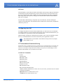
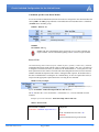
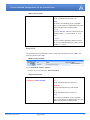
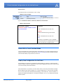
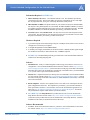
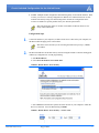
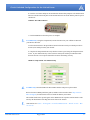
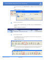
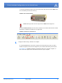
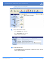
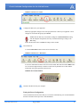
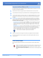
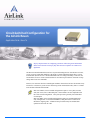
Circuit-Switched Configuration for
the AirLink Raven
Application Note - How To
Step by Step directions for configuring your Raven follow the general information
about Circuit Switch. The Step by Step directions use templates for common configurations.
The Raven in PassThru Mode does not have any internal intelligence nor does the Raven C3210,
C3216 or N3213 in PassThru Mode have the ability to SAVE individual settings like a conventional modem (the Raven C3211 in PassThru Mode can save settings internally). Therefore, the
best machines for use in circuit-switched mode are ones that can provide their own INIT or setup
strings and/or issue AT commands.
However, for customers who have unintelligent machines who still need to have the modem 'ready'
to behave in a certain way (such as Auto-Answering circuit-switched data calls), there is a feature
in the modem called the INIT STATE.
Note: For CDMA, circuit-switched configuration requires a voice plan (account)
with your carrier, not a 1xRTT data plan. 1xRTT features are not compatible with
the circuit switch configuration. Voice plan speeds are generally lower than those
of a data plan.
Note: For iDEN, circuit-switched configuration requires an account/SIM specifically configured for a Circuit-Switched Data (CSD) plan with no restriction on
inbound or outgoing calls. A SIM/account provisioned only for standard data
options will not work for CSD.
Circuit-Switched Configuration for the AirLink Raven
INIT State
The INIT STATE is a state where the modem will initialize itself by using a single pre-determined
concatenated Auto-INIT command string. In some models of the Raven, the Auto-INIT is actually an AT command itself, called +ATINIT. Since the Auto-INIT takes the shape of traditional
INIT strings, those with experience setting up conventional land-line modems should find this
fairly easy to configure.
The Auto-INIT command string is comprised of up to 40 characters, the order defining the
sequence of the initialization. The command sets the modem for the desired 'ready' configuration
each time it powers on.
Configuring Auto INIT
To configure the modem for circuit-switch communication, you will need to use AT commands.
To configure the Raven to work in PassThru mode and for circuit-switched communications, you
can use Wireless Ace (preferred) or direct serial communication.
Different models of the Raven in PassThru mode respond to some of the AT commands in different ways, a command which is used with one model may not be applicable to another.
The model number of your modem is on the label on the top of the case (example,
Raven CDMA C3211).
AT Commands and command string
Each modem requires a command string that is a combination of AT commands limited to a maximum of 40
characters. The command string will vary depending on the needs of the connected device (for example,
some devices need DTR to be high while others need DTR to be ignored). For a full listing as well as
parameters and defaults, refer to your Raven User Guide.
Common AT Commands
E Echo
Q Quiet Mode
&C DCD Control
&D DTR Options
&S DSR Options
S0 Auto-answer mode
S7 Wait for Carrier
S8 Comma Pause Time
S9 Carrier Detect Response Time
+IFC=x,x Enable or Disable Flow control - RTS/CTS (for C3210, you will need to use a comma
replacement command).
$QCVAD Answer as a Data Call for C3210.
+CICB Answer as a Data Call for C3211.
AirLink Communications
August 2006
2
Circuit-Switched Configuration for the AirLink Raven
Commands Specific to the Raven Models
For circuit-switched communication, the Raven needs to be configured to enter into PassThru after
start up (MD in the UDP group) and needs a command sent to the PassThru after it is initialized
(*PTINIT in the PassThru group).
FIGURE 1.
Wireless Ace
FIGURE 2.
Typed Commands
ATMD07
AT*PTINIT=ATstring
Caution: The only commands that can be used in the string are those which do not
require ALEOS. All AT Commands beginning with an * (asterix) require ALEOS.
Raven C3210
The command string cannot contain any spaces, commas, the plus (+) symbol, or a semi-colon (;). If an AT
command needed for the string contains a plus or comma (for example, +IFC=0,0), you will need
to designate a break character since you cannot use the standard break of ; for the plus to be read
and a replacement for the comma. The break and comma designations need to be at the end of the
ATINIT command and separated with commas. During the INIT sequence, the modem looks at
the entire command before executing the AT command string. If there are replacement values, it
will perform the appropriate replacement before executing the AT command.
FIGURE 3.
Entry Example:
AT&C1S0=1$QCVAD=4%+IFC=0^0,%,^
Typed: AT*PTINIT=AT&C1S0=1$QCVAD=4%+IFC=0^0,%,^
The % will allow the + to be used and the ^ will translate to a ,. The AT command executed
would be:
Example of executed command: AT&C1S0=1$QCVAD=4+IFC=0,0
TABLE 1. Raven
C3210
The Auto-INIT Command
Components:
AT*PTINIT=AT&D0S0=1$QCVAD=4,%,^
AT
All AT commands must start with “AT”.
*PTINIT=
Sets the initialization string in the modem.
AirLink Communications
August 2006
3
Circuit-Switched Configuration for the AirLink Raven
TABLE 1. Raven
C3210
AT
All AT commands must start with “AT”.
string
The string is a combination of AT Commands
(refer to your Raven User Guide) limited to a maximum of 40 characters. Examples below.
[,break]
Optional “BREAK” character to allow the use of a
command with a “+”. In the example, a “%” is
used.
[,comma]
Optional comma replacement character to allow
the use of a command requiring a comma. In the
example, a ^ is used.
Raven C3211
AT commands can be concatenated to create a string. Some commands, such as “+IFC”, will
need to be prefixed with “;AT”.
FIGURE 4.
Entry Example:
ATS0=1+CICB=0
Typed: AT*PTINIT=ATS0=1+CICB=0
Example of executed command: ATS0=1+CICB=0
TABLE 2. Raven
C3211
The Auto-INIT Command
Components:
AT*PTINIT=ATS0=1+CICB=0
AT
All AT commands must start with “AT”.
*PTINIT=
Sets the initialization string in the modem.
AT
All AT commands must start with “AT”.
string
The string is a combination of AT Commands
(refer to your Raven User Guide) limited to a maximum of 40 characters. Examples below.
AirLink Communications
August 2006
4
Circuit-Switched Configuration for the AirLink Raven
Raven N3213
AT commands can be concatenated to create a string.
FIGURE 5.
Entry Example:
ats0=1;+ws46=23;+ws45=0;+wvclass=9
Typed: AT*PTINIT=ATS0=1;+WS46=23;+WS45=0;+WVCLASS=9
TABLE 3. Raven
N32131
The Auto-INIT Command
Components:
AT*PTINIT=ATS0=1;+WS46=23;+WS4
5=0;+WVCLASS=9
AT
All AT commands must start with “AT”.
*PTINIT=
Sets the initialization string in the modem.
AT
All AT commands must start with “AT”.
string
The string is a combination of AT Commands
(refer to your Raven User Guide) limited to a maximum of 40 characters. Examples below.
Raven LEDs in Circuit-Switched Mode
Just as when the Raven is in Pass Thru mode, when the Raven is in Circuit-Switched mode, the
LEDs on the front will behave differently. The Chan, Link, and Reg LEDs will flash in tandem,
while all other LEDs (except for Power) will be off.
Step by Step Configuration for the Raven
The first thing you need to do is determine the model number of your Raven. Different model
numbers will have different configurations. Some of the configuration steps for one model will not
work at all with any other model number.
The model number for your Raven is on the sticker which is on the top of the modem (example,
Raven CDMA C3210, Raven CDMA C3211, or Raven iDEN N3213). The first letter and number (C3 or N3) idicates the communication technology your modem uses. The next number (2)
indicates the modem model (Raven). The final two numbers (10, 16, or 13) indicate the internal
hardware model.
AirLink Communications
August 2006
5
Circuit-Switched Configuration for the AirLink Raven
Information Required for CDMA only
1.
Master Subsidy Code (MSL) - also called the Unlock Code. This should be provided by
your Wireless Provider. The incorrect MSL can cause the configuration to fail. This might
also be programmed for you as part of the Setup Wizard activation process.
2.
MIN and MSN or MSID - The phone number for your cellular account (also called the MIN).
You may have two phone numbers for your modem, the MIN and MSN or MSID. If you have
two numbers which are different and you only enter one, the configuration will fail. The MIN
and MSN or MSID (if it is different) should be provided by your Wireless Provider
3.
Username (SID or NID) and Password - You may also need a user name and password for
your account. The user name for your account may be the same as your MIN. The user name
and password should be provided by your Wireless Provider
Hardware Required
1.
A personal computer with a functioning serial port or USB port and a USB to serial converter
configured to work with your computer.
2.
A straight through RS232 cable (DB9M-DB9F).
3.
A suitable power supply and antenna for the Raven modem. Without suitable signal strength
the modem will not function. Better than at least -100dBM is required.
4.
For iDEN only: An iDEN SIM specifically provisioned for Circuit-Switched data and has no
restrictions on incoming/outgoing calls.
Software
1.
Modem Doctor - Utility to conduct diagnostics and to bring your modem to a base-level of
configuration. You can download Modem Doctor from the AirLink website: http://www.airlink.com/support/modems/utilities/ (scroll to the bottom of the page for the link to download).
This utility does not need to be installed; it is run directly. Remember where you downloaded it
to, so you can run it as part of the instructions below.
2.
Wireless Ace - Graphical interface for entering most AT Commands. You can download Wireless Ace from the AirLink website: http://www.airlink.com/support/modems/utilities/ (scroll to
the bottom of the page for the link to download). A default installation of this utility is assumed
later in these directions
3.
Raven Templates - Wireless Ace templates for the C3210 and C3211 in both quiet and non
quiet configurations and N3213. The templates are provided by your AirLink Communications representative and have a .xml extension. You can also download the appropriate template from: ftp://ftp.airlink.com/pub/Docs/AppNotes/CircuitSwitchTemplates/. You should
only download the template which matches your modem model.
4.
For CDMA only: The Setup Wizard for your Wireless Provider. You can download the
Setup Wizard from the AirLink website: http://www.airlink.com/support/modems/utilities/
(select Raven and your Wireless Provider to download the correct Setup Wizard). A default
installation of this utility is assumed later in these directions.
Software Recommended
1.
AirLink Communications
AceView - Status and connection monitor for your Raven. You can download AceView from
the AirLink website: http://www.airlink.com/support/modems/utilities/.
August 2006
6
Circuit-Switched Configuration for the AirLink Raven
2.
AceNet - Multiple modem configuration and monitoring utility for all AirLink modems. With
AceNet, you can save a working configuration in Wireless Ace and then load it into several
modems concurrently saving time and ensuring all the modems are configured the same.
AceNet is available for seperate purchase from your AirLink representative.
Note: The monitoring feature of AceNet is unavailable for Ravens which are cur-
rently in Pass-Thru mode.
Configuration Steps
1.
Connect the modem to your computer (or USB to serial device connected to your computer) via
the RS232 cable and apply power to the modem.
Note: If this is the first time you are activating the modem, skip to step 3 (CDMA)
or 4 (iDEN).
2.
The Raven should have the internal memory erased to bring the modem to a known starting point
without any configuration or account programming.
a. Start Modem Doctor.
b. Select Erase the modem's non-volatile data.
FIGURE 6.
Modem Doctor: Erase memory
c. Select Serial from the Interface options and select the Port on your computer to which the
Raven is connected. Leave the Baud setting at 115200.
FIGURE 7.
AirLink Communications
Modem Doctor: Erase memory - connect serial
August 2006
7
Circuit-Switched Configuration for the AirLink Raven
d. Click the Next button and press the modem Reset button when prompted. The modem Reset
button is located on the front panel of the modem and can be accessed with the point of a pen or
similar tool.
FIGURE 8.
Raven Reset Button
e. Click the Exit button when the process is complete.
3.
For CDMA only: Using the Setup Wizard, activate the Raven for your cellular account with
your Wireless Provider.
a. Follow the directions in the Quick Start Guide for the Raven and your cellular provider to
activate (also called provision) your modem.
b. Complete the Setup Wizard and verify that the account is good using the Setup Wizard test
screen. If your modem fails any of the tests then contactyour cellular providerand troubleshoot the account. Do not proceed until the account is functioning correctly.
FIGURE 9.
4.
Setup Wizard: Test Modem Setup
For iDEN only: Insert the SIM in the Raven iDEN modem and power up the modem.
Refer to the Raven iDEN Quick Start guide (available on the AirLink website: http://www.airlink.com/support),for instructions on how to install the SIM in your modem.
The modem should come up and register on the iDEN network in packet-switched mode as indicated by the illumination of the Reg LED on the front of the modem.
5.
AirLink Communications
Start Wireless Ace: Start > All Programs > AirLink Communications > Wirelss Ace 3G > Wireless Ace 3G
August 2006
8
Circuit-Switched Configuration for the AirLink Raven
Click the Connect button. Select PPP, COM1 and enter 12345 for the password and then click
OK.
FIGURE 10.
6.
Wireless Ace: Connect
Configure the serial port speed.
On the left, under the GROUPS heading, select Serial. Change the *MODEMHISPEED setting to “0”.
FIGURE 11.
7.
Wireless Ace: Serial Port
Save the setting to the modem.
Click the Write button on the tool bar of Wireless Ace and wait for the message “Write Successful” to appear in the status bar.
FIGURE 12.
Wireless Ace: Write
b. Click the Clear button and then the Disconnect button on the tool bar of Wireless Ace.
FIGURE 13.
AirLink Communications
Wireless Ace: Clear and Disconnect
August 2006
9
Circuit-Switched Configuration for the AirLink Raven
c. Press the modem Reset button on the front of the modem. Wait until the modem REG indicator is lit and then proceed to the next step.
FIGURE 14.
Raven Reset Button
Caution: Do not proceed to the next step before the REG indicator light is lit.
d. Click the Refresh All button on the tool bar of Wireless Ace and wait until all of the modem
information is loaded into the Wireless Ace application.
FIGURE 15.
8.
Wireless Ace: Refresh All
Configure the Raven using a Wireless Ace template.
h. Click the Load button on the tool bar. Change to the folder (directory) where you downloaded the template(s) and select the template for your modem model and/or prefered mode.
For CDMA only: If landline emulation is desired then choose the “non-quiet” template. If
direct serial cable replacement is desired then choose the “quiet” template.
AirLink Communications
August 2006
10
Circuit-Switched Configuration for the AirLink Raven
FIGURE 16.
9.
Wireless Ace: Load Template
Configure additional PassThru settings.
a. For *PTREFRESH, enter a value of 15.
b. For *RESETPERIOD, enter a value of 6.
FIGURE 17.
Wireless Ace: PassThru
15
6
10.
Save the setting to the modem.
a. Click the Write button on the tool bar of Wireless Ace and wait for the message “Write Successful” to appear in the status bar.
AirLink Communications
August 2006
11
Circuit-Switched Configuration for the AirLink Raven
FIGURE 18.
11.
Wireless Ace: Write
Configure the Raven for your equipment.
Make any appropriate changes to the serial port parameters to match your equipment. These
changes are made under the group option Serial.
Caution: Do not under any circumstances change the *MODEMHISPEED setting
from the template configuration, the only recommended setting to change is the
S23 setting.
Follow the directions above to Write the changes to the modem.
12.
Reset the Raven.
a. Click the Disconnect button on the tool bar of Wireless Ace.
FIGURE 19.
Wireless Ace : Disconnect
b. Press the modem Reset button on the front of the modem. Wait until the modem REG indicator is lit and wait approximately 2 minutes to make sure all parameters are written and the
modem has once again registered on the network.
FIGURE 20.
13.
Raven Reset Button
Diconnect the Raven from your computer.
Testing the Raven Configuration
Once the modem has been activated and you’ve built the command string it is recommended that
the Raven modem be tested previous to field installation.
AirLink Communications
August 2006
12
Circuit-Switched Configuration for the AirLink Raven
1.
Verify that the modem Chan, Link and Reg indicators are blinking in unison confirming that the
modem is now operating in circuit switched (IS-95) mode.
2.
For iDEN only: Using a terminal emulation program (HyperTerminal) set up for 9600bps, 8 data
bits, no parity and 1 stop bit, verify the settings in the Raven. En utilisant un programme d'émulation terminale (HyperTerminal) installez pour 9600bps, 8 bits d'informations, aucune parité et 1
bit d'arre4t, vérifient les arrangements dans Raven.
a. Enter the command: AT. If you do not receive a reply of “OK”, enter ATE1 to enable the
echo mode.
b. Enter the command: AT&V.
c. Review the settings and confirm that the parameters are correct: +WS45=0, +WS46=23 and
+FCLASS=0.
FIGURE 21.
HyperTerminal: AT&V
d. Enter the command: AT+WVCLASS?. Confirm that a response of "+WVCLASS: 9" is
returned.
e. Enter the command: ATS0?. Confirm that a response of "001" is returned.
3.
Dial the Raven modem telephone number from a land line and verify that the modem automatically answers the call with modem tones.
Note: This test should be completed with the serial cable disconnected to verify
that no signaling is required by the modem.
4.
Using a terminal emulation program (HyperTerminal) set up for 9600bps, 8 data bits, no parity
and 1 stop bit, verify outgoing calls.
Enter the command: ATD<phone number>. For the <phone number>, enter a known phone
number including the area code for which you can hear ring (such as your office phone).
AirLink Communications
August 2006
13
Circuit-Switched Configuration for the AirLink Raven
Commission the Raven Modem on Site
The following steps represent a guideline and makes assumptions that the modem has been verified
previously in a controlled environment.
1.
2.
3.
Install the Raven modem verifying that all power and antenna cables are correctly secured.
4.
For CDMA only: Using a terminal emulation program (HyperTerminal) set up for 9600bps, 8
data bits, no parity and 1 stop bit, verify the signal strength. En utilisant un programme d'émulation terminale (HyperTerminal) installez pour 9600bps, 8 bits d'informations, aucune parité et 1
bit d'arre4t, vérifiez la force de signal.
Verify that the Raven modem powers up and that the Chan, Link and Reg lights blink in unison.
Connect the Raven modem to the laptop computer via a straight through RS232 cable or connect
the serial cable from the modem to a USB to serial device that has been previously installed on
the laptop.
For the Raven C3210: Enter the command: AT!RSSI?. This will respond back with a signal
strength measurement represented in dBm. The value must be better than -100dBm for the
modem to function and it is strongly recommended that -90dBm or better be used as a minimum value.
For the Raven C3211: Enter the command: AT+CSQ?. This will respond back with a signal
strength measurement represented on a scale from 0-31 and second value separated by a
comma. The signal strength value must be higher than 9 for the modem to function and it is
strongly recommended that a value of 18 or better be used as a minimum value.
You can use the A/ command to repeat the last AT command.
5.
6.
Remove the connection to the Laptop PC and connect your equipment to the Raven Modem.
Have the actual application call your equipment via the modem telephone number and verify
communications.
AirLink Technical Support
If you encounter problems with operation of your AirLink modem, AirLink’s support staff can
help.
Caution: The configuration suggestions offered in this guide are not supported nor is any
equipment other than AirLink products. Only the operation of the modem or software
obtained directly from AirLink is supported.
Refer to the User Guide for your modem or the AirLink website for AirLink product warranties.
AirLink Communications
August 2006
14
Circuit-Switched Configuration for the AirLink Raven
AirLink Support Web Site
The AirLink web site is updated frequently with Setup Wizards, Utilities, How-To Guides, and
other documentation: http://www.airlink.com/support.
AirLink Documentation and Guides
• Modem User Guides - These guides are specific to your modem type, cellular provider, and
cellular technology and contain comprehensive information about the operation of the modem
and its features.
• Modem Quick Start Guides - These guides are also specific to the modem type, cellular provider, and cellular technology and are a step by step guide to activating the modem using the
Setup Wizard or other steps as applicable.
• Utility Guides - These guides focus on the features of one of the AirLink modem utilities:
Wireless Ace, AceView, AceNet, Modem Doctor, etc.
• How-To Guides and Application Notes - These guides detail configuring the modem to work
with a specific feature set or how the modem can be set up to work with a specific 3rd party
(non-AirLink) device.
• Data Sheets and White Papers - These are technology based information documents.
Contacting Technical Support
For support assistance please email [email protected] or call 510-781-9760 Monday through
Friday 5 AM to 5 PM Pacific Time (8 AM to 8 PM Eastern Time). Support is not available weekends or holidays.
Information in this document is subject to change without notice.
©Copyright AirLink Communications, Inc., 1993-2006. All rights reserved.
AirLink Communications
August 2006
15