1
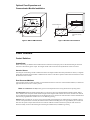
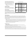
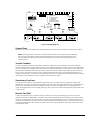
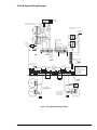
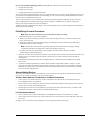
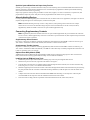
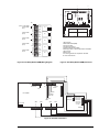
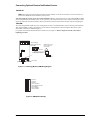
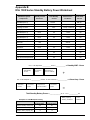
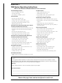
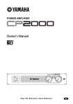
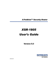
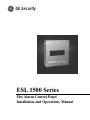
g GE Security
ESL 1500 Series
Fire Alarm Control Panel
Installation and Operations Manual
Table of Contents
Precautions and Warnings ......................................................................... 1
System Overview ......................................................................................... 1
Panel Listing ........................................................................................................................... 1
Panel Description ........................................................................................ 2
Ordering Information ................................................................................................................ 2
Installing the Panel ...................................................................................... 3
Optional Zone Expansion and Communicator Module Installation ............................................ 4
Panel Controls ............................................................................................. 4
Control Switches ..................................................................................................................... 4
Normal Condition ..................................................................................................................... 5
Alarm Condition ...................................................................................................................... 5
Alarm Verification .................................................................................................................... 5
Zone Disconnect ................................................................................................................... 5
System Reset ......................................................................................................................... 6
Trouble Condition .................................................................................................................... 6
Supervisory Functions ............................................................................................................. 6
Remote Test (Drill) .................................................................................................................. 6
Field Wiring .................................................................................................. 7
Installation Recommendations/Precautions ............................................................................. 9
Field Wiring Checkout Procedures ........................................................................................ 10
Alarm Initiating Devices ......................................................................................................... 10
Alarm Indicating Devices ....................................................................................................... 11
Connecting Supplementary Contacts .................................................................................... 11
Connecting Optional Remote Notification Devices ................................................................. 13
Programming ............................................................................................. 14
BMB Programming ................................................................................................................ 14
ZEM Programming ................................................................................................................ 14
Testing and System Checkout ................................................................. 15
Maintenance ......................................................................................................................... 15
Troubleshooting ........................................................................................ 16
Specifications ............................................................................................ 17
Appendix A, Compatible Equipment ........................................................ 18
Appendix B, Standby Battery Power Worksheet .................................... 20
Appendix C, 1500 Series Operating Instructions .................................... 21
Figures and Tables
Figures
Figure 1. Internal Panel Configuration .................................................................................... 3
Figure 2. ZEM or LEM Installation ......................................................................................... 4
Figure 3. Window Label Installation ....................................................................................... 4
Figure 4. Template Diagram ................................................................................................... 6
Figure 5. Class A System Wiring Diagram ............................................................................. 7
Figure 6. Class B System Wiring Diagram ............................................................................ 8
Figure 7. Power Limited Routing ............................................................................................ 9
Figure 8. Zone Relay Module (ZRM) Wiring Diagram ........................................................... 12
Figure 9. Zone Relay Module (ZRM) Placement ................................................................... 12
Figure 10. Terminal Connections ......................................................................................... 12
Figure 11. Local Energy Module (LEM) Wiring Diagram ....................................................... 13
Figure 12. BMB Default Settings ......................................................................................... 13
Figure 13. ZEM Default Settings .......................................................................................... 14
Figure 14. ZEM Programming Switches Location ................................................................ 14
Tables
Table 1. Ordering Information ................................................................................................. 2
Table 2. Status Indicators ...................................................................................................... 5
Table 3. Wire Resistance ...................................................................................................... 9
Table 4. Alarm Indicating Circuit Wire Size ............................................................................ 9
Table 5. BMB Programming Features .................................................................................. 14
Table 6. ZEM Programming Features .................................................................................. 14
Table 7. Troubleshooting Guide ........................................................................................... 16
Table 8. Compatible Indicating Devices ................................................................................ 18
Table 9. Two-Wire Smoke Detector Compatibility ................................................................ 19
Table 10. Four-Wire Smoke Detector Compatibility ............................................................. 19
Precautions and Warnings
The equipment described in this manual is Listed by Underwriters Laboratories, Inc. for use in fire alarm signaling systems, only
when installed in accordance with this manual and National Fire Protection Association’s National Fire Alarm Code (NFPA 72); the
National Electrical Code (NFPA 70); the Life Safety Code (NFPA 101); and the local authority having jurisdiction (AHJ). The
installer must be familiar with and understand all applicable codes before beginning installation.
To ensure proper operation of this equipment:
•
•
•
•
Do not deviate from any installation instructions contained in this manual.
Do not assume any installation details not shown in this manual.
Do not alter any mechanical or electrical features of the equipment supplied.
Be familiar with the building code, fire prevention code, and/or other authority having jurisdiction (AHJ) in the locale of
the installation.
It is the responsibility of the installer to ensure that the wiring and devices installed in the system meet current
national electrical code, NFPA standards, and state and local building code requirements.
WARNING
Under abnormal conditions, AC line voltages may be present on any terminal. Touching any component could be
hazardous and result in loss of life. A short circuit can result in arcing that could cause molten metal injuries to
testing personnel.
To minimize this possibility, only qualified technicians familiar with electrical hazards should perform these
procedures. Safety glasses should be worn by such personnel, and instruments used for voltage measurement
should be designed for the purpose and should be in good mechanical and working order.
If any application or installation information is not understood, or is not covered in this manual, please contact:
Technical Support: 800.648.7424
Sales: 800.547.2556
System Overview
The ESL 1500 Series Control Panels are designed to provide reliable and economical fire alarm control solutions for commercial,
industrial, residential, and institutional applications. The 1500 Series consists of three base models, equipped with one (Model
1501), three (1503), or five (1505) zones. The unique modular design makes it easy and practical to add features such as extra
relays, remote annunciators or added fire zones (up to 5).
All models come equipped with a Basic Master Board (BMB), which provides all common system functions for alarm, fault, and
supervisory monitoring, together with one initiating and two indicating circuits. Models 1503 and 1505 also include Zone
Expander Modules (ZEM), expanding the systems capability from three zones up to a maximum of five zones.
One housing is common to all three system configurations. The cabinet holds all standard and optional modules as well as
necessary standby batteries for either 24 or 60 hour protection.
Combine the versatile 1500 Series with the complete line of compatible ESL smoke detectors, pull stations, and indicating devices
for a reliable fire control system. See Appendix A for a list of UL Listed compatible devices.
Panel Listings
All 1500 Series systems function in accordance with the National Fire Alarm Code (NFPA 72) for the following types of systems:
Control Station Signaling Systems
Local
Auxiliary
Types of Signaling Service
Automatic Fire Alarm
Manual Fire Alarm
Waterflow Alarm
Supervisory Fire Alarm (NFPA 72 local only)
Elevator Recall
The 1500 Series is currently listed by these organizations:
UL 864
California State Fire Marshall #7165-0447-121
MEA (New York City) #472-86-SA
ESL 1500 Series Fire Alarm Control Panel
1
Panel Description
Standard Features:
Optional Features:
•
•
•
•
•
•
•
•
•
•
•
•
Modular design; 1, 3, or 5 zones
Power limited
1.5 Amp. 24 VDC FWR output
Local Energy Module (LEM)
Zone Relay Module (ZRM) 5 relays
Remote Annunciators (RA)
All functions DIP switch activated
Built-in walktest and alarm verification
Sprinkler supervisory and waterflow alarm activation
Class A (Style D) or Class B (Style B) initiating wiring
Reliability of surface-mount design
Superior lightning protection
Table 1. Ordering Information
2
Model
Title
Description
1501
Single zone fire panel
1 initiating circuit,
2 indicating circuits
1503
Three zone fire panel
3 initiating circuits,
2 indicating circuits
1505
Five zone fire panel
5 initiating circuits,
2 indicating circuits
1500-BMB
Basic Master Board
1 initiating circuit,
2 indicating circuits
1500-ZEM
Zone Expansion Module
2 initiating circuits,
Class A or B
1500-LEM
Local Energy Module
Connect to Listed
master box
1500-ZRM-5
1500 Zone Relay Module
5 relays
1500-SH
System housing
System housing
with transformer
1500-TK
Flush mount trim ring
Mounting panel
semi-flush with wall
1500-TR
Transformer
Transformer
replacement
1500-2.7
End-of-line resistor
Initiating and
indicating circuits
2.7 Ky 1/2 W
1500-RA-5A
Remote Annunciator
5 alarm zones w/
trouble and
sounder
204-12/24 V
Power supervision unit
EOL power
supervisory unit
405-01
Polarity reversal relay
Single circuit,
24 VDC
ESL 1500 Series Fire Alarm Control Panel
Installing the Panel
To install the unit, follow these 12 steps, and refer to the proper sections for more information.
1.
Create System Diagram: Prepare a carefully laid out drawing of the complete wiring system hookup. Maintain this
drawing as a permanent record of the system application and include any future modifications.
Note: “As-built” drawings and this manual should be available at all times to verify agreement between the
connected equipment and the drawings.
2.
Inspect Equipment: Carefully unpack the system components and inspect for shipping damage. Report any shipping
damage to place of purchase.
3.
Mount Cabinet: Mount the cabinet in a clean, dry, vibration-free area, where the temperature range does not exceed 0°
to 49° C (32° to 120° F). Mount only in interior locations. Allow adequate space for 180 degree door swing and free
access to sides for conduit entry. Locate the top of the cabinet approximately 6 feet (1.8m) above the floor, with the hinge
mounting on the left. Mounting holes in the back of the cabinet are designed so the cabinet can be mounted without removing
any control equipment. Mount the cabinet to the wall by first installing the top center mounting screw, leaving enough space
so the cabinet can be hooked over the screw head. Use screws or bolts no smaller than #10 or 3/16 inches in diameter. For
easier access, remove the door by gently lifting it from the hinges.
4.
Connect Conduit: Complete all connections to the cabinet with conduit fittings or bushings. Use the knockouts provided in
the sides of the cabinet.
5.
Pull Wire: Pull all system wiring through installed conduit following the guidelines of Article 760 of the National Electrical
Code (NFPA 70) and/or local codes for fire alarm systems. Observe power limiting codes when running wire.
See Installation Recommendations/Precautions for more information.
6.
Program Components: Before wiring, examine installation of all modules, chassis and sub-assemblies to ensure proper
mechanical and electrical connections and programming switches have been selected. See Programming for options.
7.
Connect AC: Connect line voltage to transformer leads located under the BMB. Transformer wires are long enough
so you do not need to remove the circuit board.
8.
Connect Batteries: Determine the total system power requirements by using the Standby Battery Power Worksheet
in Appendix B.
9.
System Check: Make certain the 1500 panel is operating properly before connecting field wiring by performing a
system check. ESL makes this easy by factory installing end-of-line resistors to the proper Class B zone terminals. To test
the panel, make sure all switches are in their normal position and power the system by connecting AC and then the
batteries. (Note: if new batteries with low terminal voltage are used, the Low/No Battery LED may activate. The Low
Battery indicator will deactivate after the batteries are fully
charged - no longer than 48 hours.) No fault indications
1
2
should be present. If faults are present, see Table 6. Troubleshooting Guide. System check is now complete.
Zone #1 trouble
Supervisory
Low/no AC
Low/no battery
Ground fault
Indicating #1 trouble
Indicating #2 trouble
3
ON
10
11. Connect Field Wiring: Connect each circuit in turn,
following wiring diagrams provided. Do not make all
connections at once. This procedure will let you bring your
system on-line in stages and quickly identify which portion of
your system is not working.
1 2 3 45 6 7 8
10. Check Field Wiring: Check the integrity of all field wiring
following directions defined in the Field Wiring Checkout
Procedures.This check must be performed before connecting
wiring to the system. Be certain all external wiring is correct
(no opens, shorts, or grounds) and is terminated with the
correct end-of-line devices.
4
9
5
Note: NFPA 72, Chapter 7 - Inspection, Testing, and
Maintenance should serve as the guideline for all system tests.
12. Test System: Apply power and perform operational tests as
outlined under Testing and System Checkout.
CAUTION
Read and understand all instructions before beginning
installation. System reliability depends upon proper
installation, testing, and maintenance. Review all national
and local codes before attempting installation. Refer to
National Fire Alarm Code (NFPA 72) for proper location,
mounting, etc. of smoke detectors, heat detectors, and
other alarm initiating devices. Call Technical Support at
800.648.7424 if you have installation questions.
ESL 1500 Series Fire Alarm Control Panel
8
7
6
1. Mounting hole
2. Basic Master Board (BMB)
3. Housing backbox
4. Programming switches
5. Zone Expander Modules (ZEM)
6. Mounting location for Zone Relay Module 1500-ZRM-5
7. Mounting hole (TYP)
8. Battery area
9. Local Energy Master Box Trip Module 1500-LEM
10. 1500-TR Transformer
Figure 1. Internal Panel Confirguration
3
Optional Zone Expansion and
Communicator Module Installation
24 VAC
AC IN
Z1RA– SYSTEM COM NO
+15VDC
CASE Z1B+ Z1A+ Z1A– Z1B– AUX SYS FIRE
GROUND
24VFWR GND DRILL
ZONE 1
NC COM
TROUBLE RELAY
ZONE
NC
NO
B–
ALARM RELAY
B+
1 TROUBLE
SUPERVISORY
INDICATING
LOW/NO AC POWER
1
LOW/ NO BATTERY
GROUND FAULT
SENTROL, INC.
10831 SW
Boulevard
12345
SW Cascade
Leveton Dr.
Tualatin,
9706297223
Portland,OR
Oregon
A–
B–
INDICATING
2
SYSTEM
WALKTEST
ZONE 1
POWER LIMITED
24 VDC
BATTERY IN
NORMAL
NORMAL
RESET
SOUNDER
SILENCE
B+
A+
A–
NORMAL
DISCONNECT
AC
POWER
LEM
A+
INDICATING 1 TROUBLE
INDICATING 2 TROUBLE
ZEM
SYSTEM
TROUBLE
ZONE
ALARM
1
NOT USED–8
NOT USED–7
NOT USED–6
ZONE 2 SUP.–5
ZONE 1 RA–4
SILENT WALKTEST–3
ZONE 1 WATERFLOW–2
ALARM VERIFICATION–1
ZEM
Figure 2. ZEM or LEM Installation
1505 window label shown
The window label must be
changed when expanding
zones.
Figure 3. Window Label Installation
Panel Controls
Control Switches
System Reset
Resets control unit, provided the alarm condition has been cleared. Also interrupts power to the alarm initiating circuits of all
zones and to the auxiliary power output. The integral sounder will activate when the System Reset switch is activated.
Sounder Silence
Activating the switch during a trouble condition will silence the integral sounder. When all system faults are cleared, a “ringback”
feature will resound the integral sounder to indicate that the switch is in the silence position. Fault LEDs will remain active until
all faults have been corrected.
Zone Disconnect/Walktest
A three position switch provides for normal, test, and disable functions for each zone. Under standard conditions, no LEDs will
light when the switch is in the “normal” position.
Note: For maintenance use only! Notify your local fire department and receiving station before operating switch.
Zone Disconnect disables the alarm indicating devices so that service may be performed without sounding an alarm. When a
zone is disabled, zone and system trouble LEDs will light and the integral trouble sounder will activate. An alarm received from
any zone that has not been disabled will activate the indicating devices as normal. The zone disconnect switch is defeated when a
zone has been programmed for waterflow service. See BMB Programming.
Walktest makes it possible for one service person to functionally test initiating devices without having to constantly return to
reset the control panel. When activiated, the walktest feature sounds the indicating devices for approximately two seconds and
then resets the system. Only an alarm from the zone with the walktest activated will reset the system; all other zones will
function normally. To silence the indicating devices during the walktest mode, see BMB Programming.
4
ESL 1500 Series Fire Alarm Control Panel
Optional Remote Notification Disconnect
Applies to LEM optional module. Disconnects system
from remote sites. When activated, the trip circuit fault
LED and system fault condition will exist and remain until
the switch is returned to the normal position.
Note: Notify the local fire department and the
receiving station before disconnecting the LEM
from the system.
Table 2. Status Indicators
Indicator
Normal
Color
Description
AC Power
On
Green
Indicates main power is
operating from AC power
source. If LED not
activated, service
immediately.
System
Trouble
Off
Yellow
Indicates fault or
abnormal condition. May
indicate system is
inoperable; service
immediately.
Normal Condition
Under normal operating conditions only the green “AC
POWER” LED should be on (no alarm or faults). All
control switches must be in their normal, standby position.
Alarm Condition
An alarm can be initiated by means of a smoke detector,
Zone Alarm
Off
Red
Indicates when an alarm
(by zone)
condition is detected by
heat detector, manual alarm station, waterflow alarm
its zone.
device, or other UL Listed initiating device. The red zone
alarm LED will light and the integral sounder will provide a
continuous, steady audible signal. Both alarm indicating circuits will activate and sound a general alarm. A set of dry, Form C
supplementary common alarm contacts will transfer and remain latched until the system RESET switch is operated. When used,
the supervised zone alarm output will energize. If provided, the remote communicator circuit will activate to summon organized
assistance.
Alarm Verification
When activated, alarm verification is very effective in reducing nuisance alarms. Nuisance alarms are reduced by requiring 2
separate alarm signals to activate the system When the first alarm is received from an initiating device, the verification feature
inhibits an alarm output for approximately 12 seconds. After this period, power is reapplied to the initiating circuits. If a second
alarm signal is received within 2 minutes, a system alarm is generated; if not, the system resets and no alarm is generated. An
alarm from a manual station or heat detector, however, is never delayed more than 15 seconds. To activate alarm verification, see BMB Programming.
Note: When using alarm verification, total alarm delay (alarm verification + smoke detector power-up time) cannot exceed
60 seconds according to the National Fire Alarm Code (NFPA 72) or 30 seconds for installations governed by the California
State Fire Marshall. Alarm delay includes verification time (12 seconds) and smoke detector power-up time. Smoke detector
power-up time varies by manufacturer, however, the ESL 429, 449, 521, 541, 500N, and 700 Series detectors meet both
CSFM and NFPA requirements (ESL detector power-up time is 15 seconds).
During alarm verification, the Zone LED, Remote Annunciator and the Zone Relay Module (ZRM) may activate briefly
(approximately 12 seconds) during the initial alarm signal.
Zone Disconnect
Note: For maintenance use only! Notify local fire department and receiving station before operating the switch
if the control panel is monitored, as a “trouble” signal will be transmitted.
When activated prior to an alarm condition, this switch disconnects the local zone alarm from the auxiliary alarm relay and
alarm indicating circuits. When activated, the red local alarm zone LED turns on and, if used, the supervised remote annuncitator
LED lights. Only the disconnected zone is affected; alarm signals from other zones remain active.
When activated after an alarm condition, the auxiliary alarm relay remains latched and alarm indicating circuits are turned off.
The red local alarm zone LED remains on and, if used, the supervised remote annunciator remains on. Only the disconnected zone
is affected; alarm signals from other zones remain active. Additionally, if an initiating device is still in alarm when a zone disconnect switch is returned to normal, the alarm will again be transmitted to both the alarm indicating circuits and the integral sounder.
ESL 1500 Series Fire Alarm Control Panel
5
Z1RA– SYSTEM COM NO
+15VDC
CASE Z1B+ Z1A+ Z1A– Z1B– AUX SYS FIRE
24VFWR GND DRILL
GROUND
24 VAC
AC IN
ZONE
1
NC
COM
TROUBLE RELAY
ZONE
NC
NO
B–
ALARM RELAY
B+
1 TROUBLE
SUPERVISORY
LOW/NO AC POWER
1
LOW/NO BATTERY
B–
INDICATING 1 TROUBLE
INDICATING 2 TROUBLE
NORMAL
WALKTEST
ZONE 1
POWER LIMITED
24 VDC
BATTERY IN
2
A–
DISCONNECT
2
DISCONNECT WALKTEST
Z2B+ Z2A+ Z2A-
A+
NORMAL
NORMAL
AC
POWER
DISCONNECT
TRBL ALARM
TRBL
NORMAL
NORMAL
B+
INDICATING
SYSTEM
ZONE
A–
GROUND FAULT
SENTROL, INC.
12345 SW Leveton Drive
Tualatin, Oregon 97062
COMMUNICATOR
A+
INDICATING
RESET
SOUNDER
SILENCE
SYSTEM
TROUBLE
ZONE
3
ZONE
ALARM
TRBL
NORMAL
DISCONNECT
Z2B- Z2RA- Z3B+ Z3A+ Z3A-
WALKTEST
Z3B- Z3RA-
ZONE
ALARM
4
NOT USED–8
NOT USED–7
NOT USED–6
ZONE 2 SUP.–5
ZONE 1 RA–4
SILENT WALKTEST–3
ZONE 1 WATERFLOW–2
ALARM VERIFICATION–1
1
ZONE
ALARM
TRBL
NORMAL
DISCONNECT
WALKTEST
Z4B+ Z4A+ Z4A-
5
ALARM
TRBL
NORMAL
DISCONNECT
Z4B- Z4RA- Z5B+ Z5A+ Z5A-
WALKTEST
Z5B- Z5RA-
Figure 4. Template Diagram
System Reset
System reset can only be accomplished when all actuated alarm devices have been restored to their normal, standby condition.
Note: Operating the system reset switch will return all alarm initiating circuits and system-powered inititating
devices to their normal standby condition. Mechanical initiating devices such as most fixed termperature heat
detectors and manual stations must be replaced or manually reset or the system will alarm again when the reset
switch is released.
Trouble Condition
Activation of the fault signal under normal operation indicates a condition that requires immediate correction. A fault signal
involves illumination of the system trouble LED (yellow) and individual diagnostic LED’s (yellow) generally associated with the
specific circuit affected. The integral sounder will sound a slow intermittent signal and a set of dry, Form C contacts will transfer.
Moving the SOUNDER SILENCE switch to the silence position will silence the audible trouble signal, but will not restore the
Form C contacts. Restoration to normal can only be achieved when all faults have been corrected and all switches have been
returned to normal position. Trouble reset occurs automatically when this is accomplished. If the SOUNDER SILENCE switch is
off-normal at the time all faults are clear, the “ringback” feature will alert the operator.
Supervisory Functions
Zone 2 of the control panel can be programmed for supervisory service. A common supervisory application would include
sprinkler water valve tamper switch monitoring. During a supervisory alarm, the integral sounder activates a rapidly pulsing tone
and the zone 2 red local alarm LED lights. In addition, the supervisory LED on the BMB will activate. During supervisory
trouble, the integral sounder activates a rapidly pulsing tone, zone 2 yellow local trouble LED lights and the system trouble relay
contacts transfer.
Remote Test (Drill)
A remote test (drill) function is provided for testing the 1500 System. Closing a listed normally-open switch connected to
terminals “SYS GND” and FIRE DRILL” (see Figure 5) will result in actuating both the alarm indicating circuits and the integral
sounder. The common alarm relay will not operate, nor will an optional remote notification circuit. Any alarm signaling devices
connected to the indicating circuits will be activated. During the test/drill, the indicating supervisory circuit will be tested as well,
resulting in the illumination of the indicating circuit fault LED’s and the system trouble LED. The integral sounder will sound a
slow intermittent signal.
6
ESL 1500 Series Fire Alarm Control Panel
Field Wiring
Class A System Wiring Diagram
204-12/24V
Power
supervision relay
Zone 1 is shown with 4-wire
detectors, wired in Class A (Style D)
+
+
449C
Bell circuit 1 is shown with Class A
(Style Z) wiring
Local Zone 1 alarm
(Supervised)
Connect to
120 V AC Blk
Wht
60Hz
+
+
-
System 15VDC
System trouble Auxiliary alarm
contacts
contacts
Connector from
transformer
B+ A+
1
A-
B-
6
7
9
8
10 11 12 13 14 15 16
C N/O N/C C N/C N/O
Power ON
(standby condition)
Auxiliary
power(+)
Case
ground
BMB
Zone 1
2.7K EOL
Resistor 1/2W
Fire drill
2.7K EOL
Resistor 1/2W
BMB standoff
System
GND
Optional drill
test switch
2.7K EOL
Resistor 1/2W
B-
17
B+
18
A+
19
A-
20
B-
21
B+
22
A+
23
A-
24
Connector from
24 V DC battery in
Zone 3
Zone 2
1
LEM
2
B+
A+
A-
System
trouble
B-
RA
B+
A+
A-
B-
RA
Zone 1
alarm
Zone 4
B+
A+
A-
ON
AC
power
Zone 5
B-
RA
B+
A+
A-
B-
RA
1 2 3 4 5 6 7 8
449C
+
+
-
+
+
-
8-Not used
7-Not used
6-Not used
5-Zone 2 supervisory
4-Zone 1 remote annunciator
3-Silent walktest
2-Zone 1 waterflow
1-Alarm verification
ZEM
Zone 2 & 3
2.7K EOL
Resistor
1/2W
429C
2.7K EOL
Resistor 1/2W
2.7K EOL
Resistor 1/2W
2.7K EOL
Resistor
1/2W
ZEM
Zone 4 & 5
+
+
-
Pull station
Zone 2 is shown with 2-wire
detectors, wired in Class A (Style D)
429C
+
+
-
Zone 5 is shown with 2-wire heat
detectors and pull stations, wired in
Class A (Style D)
Heat sensor
Figure 5. Class A System Wiring Diagram
ESL 1500 Series Fire Alarm Control Panel
7
Class B System Wiring Diagram
204-12/24V
Power
supervision relay
2.7K EOL
Resistor
1/2W
Zone 1 is shown with 4-wire
detectors, wired in Class B (Style B)
+
+
449C
541C
2.7K EOL
Resistor 1/2W
+
+
-
+
+
Local Zone 1 alarm
(Supervised)
Connect to
120 V AC Blk
Wht
60Hz
+
+
-
System 15VDC
System trouble Auxiliary alarm
contacts
contacts
Connector from
transformer
1
B+
A-
A+
6
B-
7
9
8
10 11 12 13 14 15 16
C N/O N/C C N/C N/O
Power ON
(standby condition)
Auxiliary
power (+)
Case
ground
Zone 1 Fire drill
BMB
BMB standoff
System
GND
Optional drill
test switch
B-
17
B+
18
A+
19
A-
20
B-
21
B+
22
A+
23
A-
24
Connector from
24 V DC battery in
Zone 3
Zone 2
1
LEM
2
B+
A+
A-
System
trouble
B-
RA
B+
A+
A-
B-
RA
Zone 1
alarm
Zone 4
B+
A+
A-
ON
AC
power
Zone 5
B-
RA
B+
A+
A-
B-
RA
2.7K EOL
Resistor 1/2W
1 2 3 4 5 6 7 8
449C
541C
Bell circuit 1 is shown with Class B
(Style Y) wiring
8-Not used
7-Not used
6-Not used
5-Zone 2 supervisory
4-Zone 1 remote annunciator
3-Silent walktest
2-Zone 1 waterflow
1-Alarm verification
ZEM
Zone 2 & 3
2.7K EOL
Resistor 1/2W
429C
521B
2.7K EOL
Resistor 1/2W
ZEM
Zone 4 & 5
+
+
-
Pull station
Zone 2 is shown with
2-wire detectors, wired in
Class B (Style B)
+
429C +
521B -
Zone 5 is shown with
2-wire heat detectors
and pull stations, wired
in Class B (Style B)
2.7K EOL
Resistor 1/2W
Heat sensor
2.7K EOL
Resistor 1/2W
Figure 6. Class B System Wiring Diagram
8
ESL 1500 Series Fire Alarm Control Panel
Table 3. Wire Resistance
3
2
1
2
1
3
5
4
6
7
8
9
10
11 12
13 14
Gauge
17
15 16
9
18
19
ESL 1500 Series Fire Alarm
Control Panel
4
20
21
22
23
24
8
1
2
1
2
3
4
5
6
7
8
9 10
1
2
3
4
5
6
7
8
5
Ohms per 1000 ft. @ 20°C of
single conductor copper wire
12
1.6
14
2.5
16
4.0
18
6.4
20
10.0
22
16.0
9 10
7
6
Table 4. Alarm Indicating Circuit Wire Size
1. Case ground
2. Power limited Zone 1 and Remote Annunciator
3. Non-power limited trouble and alarm contacts
4. Power limited bell circuits
5. Power limited Zone 2 through 5 and Remote Annunciator
6. Housing backbox
7. Battery area
8. Non-power limited LEM
9. Non-power limited 28 VAC
Total device
load (Amps)
Figure 7. Power Limited Routing
Max. ft. of paired wire from B+ to
EOL resistor
18AWG 16AWG 14AWG 12AWG
.100
1500
2500
4000
6200
.500
300
500
800
1290
1.000
150
250
400
620
(Maximum voltage drop allowable: 2 VDC)
Installation Recommendations/Precautions
Note: The 1500 System is capable of power limited operation per NEC Article 760, Section C. All circuits are
power limitedexcept: CASE GND, TRB COM, TRB NO, ALM COM, ALM NC, and LEM terminals. Non-power
limited circuits must be separated from power limited circuits by a minimum of 1/4 inches (0.6cm). See Figure 7 for
one method of routing power limited wiring.
CAUTION
Do not route LEM field wires in close proximity of high voltage wiring. LEM filed wiring must not exceed 3280
feet (1000m).
Verify wire sizes are adequate for all indicating and initiating circuits. The maximum allowable initiating zone resistance is 100
Ohms. (Exception: When ESL 2-wire smoke detectors with integral sounders are used, maximum initating zone resistance is 50
Ohms. See Table 3.)
Many audible/visual signaling appliances cannot tolerate more than a 20 percent voltage drop from the specified device voltages.
See Table 4 to determine maximum distance for wire gauge used.
Incoming AC voltage should be stable at a nominal 120 volts. This is especially important in new construction where incoming
power may be high or unstable with temporary connections often causing large, inductive voltage spikes.
Ground the system properly. The AC imput, power supply/battery charger should use an isolated ground, not a conduit
ground. Do not connect this system to a conduit or green wire circuit that also is used to power resistance heating, motors, fans,
air conditioning equipment, or florescent lighting circuits since leakage currents into the ground return could damage system
components. A separate earth ground or cold water pipe with properly bypassed water meter should be used. Provide a separate
earth ground, if water mains are non-conductive.
Run signal wires separately. Most supervised circuits use voltage or current sensing circuits which are very sensitive to
induced voltages on the sensor wiring. Therefore, under no circumstances run AC power, speaker, public address, intercom, or
switch control wiring with inductive loads in the same conduit or in the immediate vicinity of the control wiring.
ESL 1500 Series Fire Alarm Control Panel
9
Do not overlook adequate lightning protection. Lightning damage commonly occurs from three sources:
1.
Through alarm loop wiring
2.
Through AC power inputs
3.
Through earth ground or power ground connections
The 1500 System has substantial lightning protection incorporated in all three areas. However, proper lightning protection for AC
power must be accomplished where the wire enters the building. Arrestor circuitry and earth grounding should be in accordance
with Article 250 of the National Electrical Code.
There is no known protective device available which is capable of protecting equipment from damage caused by “direct hit”
strikes of lightning due to the extremely high energy released (10 million to 100 million volts @ 10,000 to 30,000 amps).
However, line surges from indirect strikes can be minimized.
Additional protection is suggested in areas subject to above-average lightning activity or induced voltage spikes and fluctuations
due to power line load switching.
Field Wiring Checkout Procedures
Note: Make sure that AC and battery power are disconnected before proceeding.
1.
Test all field wiring before connecting any equipment.
A. Make sure no unwanted voltages are present on circuit conductors and ground. They are a hazard and may prevent
proper system operation.
B. All wiring except those intentionally and permanently grounded must be tested for isolation from ground using an
insulation testing device such as a “Megger”.
Note: Caution must be exercised when using voltage generating test instruments such as a “Megger”. Damage
to equipment could result if the equipment is connected (wired) during wiring tests.
C. All wiring, other than those intentionally connected together, must be tested for conductor-to-conductor
isolation using an insulation testing device.
2.
With each circuit pair short-circuited at the end of the circuit, measure circuit resistance with an ohmeter. Record the circuit
resistance of each circuit and store this data with the control panel. Loop resistance must be less than 100 ohms on
initiating zones.
3.
Perform testing as described previously after any addition, deletion, or mechanical or electrical damage to the system
has occurred.
4.
A periodic test should be performed in accordance with the schedules recommended in NFPA 72, Chapter 7, or more
frequently, if required by the authority having jurisdiction. Whenever possible a 100 percent test should be performed.
When less than a 100 percent test is performed, a record must be maintained of the devices tested each time, so different
devices are tested in subsequent tests.
Alarm Initiating Devices
This section describes how to field wire initiating devices such as smoke detectors, pull stations, and heat detectors. Refer to
Figure 5 for Class A (Style D) and Figure 6 for Class B (Style B) wiring.
Two-Wire Smoke Detectors, Heat Detectors, and Manual Pull Stations
•
Connect only two-wire smoke detectors UL Listed as compatible to the 1500 Series Fire Control Panel. Refer to the
list of compatible detectors in Appendix A.
•
Two-wire detectors receive their power direct from the zone terminals and transmit the alarm signal via the same wires. Be
certain to observe polarity when installing detectors.
•
All initiating devices must be wired sequentially for proper supervision with the end-of-line resistor (2.7K Ohm 1/2 W)
installed after the last device. ESL has detectors available with EOL built in.
Four-Wire Smoke Detectors
•
•
Four-wire detector power is shared with indicating circuits; do not exceed total power requirements of 1.5 Amps.
Always supervise four-wire detector power with an end-of-line power supervisory device (ESL model 204-12/24V) after
the last unit.
See Figure 5 for Class A (Style D) wiring and Figure 6 for Class B (Style B) connection to the panel.
10
ESL 1500 Series Fire Alarm Control Panel
Sprinkler System Waterflow and Supervisory Devices
Normally open contact type waterflow alarm devices may be connected, along with conventional manual alarm stations or heat
detectors. All zones to which waterflow alarm devices are connected may be programmed so that the system alarm indicating
devices cannot be silenced. See Programming.
Supervisory signals for status reporting of waterflow control valves, supplies, etc. must be connected to a separate zone, and
programmed for supervisory status. Only Zone 2 can be programmed for this feature. See Programming.
Alarm Indicating Devices
Use only polarized UL Listed signaling devices rated for 24 VDC (see the list of devices in Appendix A). See Figure 5 for Class A
(Style Z) wiring and Figure 6 for Class B (Style Y) connection to the panel.
Note: Maximum indicating current per circuit is 1 Amp; however, total operating current cannot exceed 1.5 Amps.
Choose the correct wire size for maximum voltage drop of 2 VDC at the furthest device on the circuit (see Table 3).
Supplementary Alarm and Trouble Contacts are for power limited applications only.
Connecting Supplementary Contacts
Note: Supplementary Alarm and Trouble Contacts are for power limited applications only (see Installation Recommendations/Precautions). When supplementary contacts are connected to a power limited circuit, these outputs meet power limited
code and do not require separation.
Supplementary Alarm Contacts
Dry, Form C contacts are provided for controlling supplementary alarm functions from the BMB. Contacts are rated 2A @ 30
VDC resistive. Terminals are ALM COM, ALM NC, and ALM NO. Contacts transfer in alarm.
Supplementary Trouble Contacts
Dry, Form C contacts are provided for controlling supplementary fault functions from the BMB. Contacts are rated 2A @ 30
VDC resistive. Terminals are TRB COM, TRB NC, and TRB NO. The trouble relay is normally energized and will activate even
.if both AC and battery power are removed.
Optional Zone Relay Module (ZRM)
Additional relays may be added using the optional ZRM-5. Make electrical connections using Figure 8. After connections are
made, use directions in Installing Optional ZRM and Snap Track to finish the installation.
Installing Optional ZRM and Snap Track
1
Remove the protective tape from the adhesive mounting strip on the snap track supplied with the unit.
2
Mount the snap track on the lower, right side of the cabinet. See Figure 9.
3
Using the slots in the snap track as a template, drill two holes through the cabinet side wall, one near each end of the snap
track, using a #13, #14, #15, or 3/16” diameter drill and deburr.
4
Install the supplied push rivets from the outside of the cabinet through both the cabinet side wall and the snap track, driving
the push pins flush with the rivet head. In semi-flush mounting installations, install the push rivets from the inside of the
cabinet.
5
Complete electrical connections between the ZRM and the BMB before mounting it to the snap track. Then snap the
connected ZRM into the snap track with the terminals toward the front of the cabinet.
6
Dress wire leads to comply with the requirements of the National Electrical Code, Article 760, Section C.
ESL 1500 Series Fire Alarm Control Panel
11
1
2
Zone #1 trouble
Supervisory
Low/no AC
Low/no battery
Ground fault
Indicating #1 trouble
Indicating #2 trouble
ON
3
1 2 3 4 5 6 7 8
10
4
TB1
System+15 VDC of BMB
To Z1RA-of BMB
(Zone)
COM
COIL
N/O
C
N/C
COIL
N/P
C
N/C
COIL
N/O
C
N/C
COIL
N/O
C
N/C
COIL
N/O
C
N/C
1
2
3
4
5
6
7
8
9
10
11
12
13
14
15
16
17
18
19
20
21
To Z2RA-of ZEM
(Zone 2)
To Z3RA-of ZEM
(Zone 3)
To Z4RA-of ZEM
(Zone 4)
To Z5RA-of ZEM
(Zone 5)
9
K1
5
D6 D1
K2
D2
8
K3
K4
D4
K5
D5
1. Mounting hole
2. Basic Master Board (BMB)
3. Housing backbox
4. Programming switches
5. Zone Expander Modules (ZEM)
6. Mounting location for Zone Relay Module 1500-ZRM-5
7. Mounting hole
8. Battery area
9. Local Energy Master Box Trip Module 1500-LEM
10. 1500-TR Transformer
Figure 9. Zone Relay Module (ZRM) Placement
TB2
Case Ground
6
D3
Figure 8. Zone Relay Module (ZRM) Wiring Diagram
TB1
7
TB3
ALM NO
Tip
ALM NC
SYS-
TRB NC
ESL 1500 BMB
TRB NO
TRB COM
Trouble input
Trouble input
RA+15
Z1RAZ2RA-
Z3RA-
Z4RA
Z5RA-
Communicator
Zone 1 input
Zone 2 input
Zone 3 input
Zone 4 input
Zone 5 input
+ 15 VDC
1500 RA5A
Figure 10. Terminal Connections
12
ESL 1500 Series Fire Alarm Control Panel
Connecting Optional Remote Notification Devices
1500-RA-5A
Note: When using remote annunciators other than the ESL 1500-RA-5A, be sure all circuits have a series resistance of at
least 1K ohm. Maximum current should be 15mA per zone.
The control unit can properly power one remote annunciator. When a remote annunciator is used, both the BMB and ZEM
must be programmed to provide supervision. See Programming. The remote annunciator circuit is supervised as long as no other
devices are connected to the same terminals; otherwise, the devices will not be supervised. See Figure 10 for the wiring diagram.
1500-LEM
The Local Energy Module (LEM) trip circuit is designed to interface to a Listed Master Box with a local energy trip mechanism.
This optional module provides a supervised trip circuit from the 1500 system that activates the Master Box upon a system
alarm. Make connections as detailed in Figure 11.
For systems which include remote annunciation 1500-RA-5A, use Figure 10. Remove all power from the system before
beginning procedure.
1
TB1 (opposite side)
2
Local Energy Master box trip
module (LEM)
+
K2
Master box trip coil 14.6
Ohms, 24 VDC 0.26A
min. 0.35A max.
- 24 V alarm output
Max. line resistance 10 Ohms
R9
P5
City fire alarm ckt.
I
DS1 (trouble)
Disconnect
Normal
1 2 3 4 5 6 7 8
ON
Figure 11. Local Energy Module (LEM) Wiring Diagram
8-Not used
7-Not used
6-Not used
5-Zone 2 Supervisory
4-Zone 1 Remote Annunciator
3-Silent Walktest
2-Zone 1 Waterflow
1-Alarm Verification
Figure 12. BMB Default Settings
ESL 1500 Series Fire Alarm Control Panel
13
Programming
BMB Programming
All programming selections are controlled by switches located in the lower right corner of the BMB. Table 5 shows default
(factory) prgramming along with a description of each feature.
Table 5. BMB Programming Features
Switch Factory
#
Position
Feature
Description
8,7,6
off
not used
not used
5
off
zone 2 supervisory
Disables fire alarm signal and provides distinctive audible and visual supervisory signals. Must also program ZEM zone 2 switches 3, 4, 5, & 6. See ZEM
Programming.
4
off
zone 1 remote
Provides supervised annunciator connection to remote alarm indicator.
3
off
silent walktest
Silences indicating circuits 1 & 2 during walktest mode. See Zone
Disconnect/Walktest.
2
off
zone 1 waterflow*
Disables alarm disconnect switch. Signals cannot be silenced.
1
off
alarm verification
Two consecutive alarm input signals required for alarm output. See Alarm
Verification.
* Do not program zone for waterflow in conjunction with walktest because the communicator or optional LEM module may
transmit an alarm condition. In addition, the sytem alarm relay will be activiated.
ZEM Programming
All programming selections are controlled by switches located in the front right center of the ZEM. Table 6 shows default
(factory) programming along with a description of each feature.
Table 6. ZEM Programming Features
Switch Factory Feature
#
Position
Description
8
off
zones 3 & 5 waterflow*
Alarm disconnect switch enabled. Signals can be silenced.
7
off
zones 2 & 4 waterflow*
Alarm disconnect switch enabled. Signals can be silenced.
6
off
zone 2 supervisory
Fire alarm signal enabled. Yellow supervisory LED on 1500-BMB is diabled.
See Supervisory Functions.
5
off
zone 2 supervisory
Fire alarm signal enabled. Yellow supervisory LED on 1500-BMB is disabled.
See Supervisory Functions.
4
on
zone 2 supervisory
Fire alarm signal enabled. Yellow supervisory LED on 1500-BMB is disabled.
See Supervisory Functions.
3
on
zone 2 supervisory
Fire alarm signal enabled. Yellow supervisory LED on 1500-BMB is disabled.
See Supervisory Functions.
2
on
zone 3 & 5 Remote
Annunciator
Connection to remote indicator not supervised.
1
on
zone 2 & 4 Remote
Annunciator
Connection to remote indicator not supervised.
ON
1 2 3 4 5 6 7 8
* Do not program zones for waterflow in conjunction with walktest because the communicator or optional LEM module may
transmit an alarm condition. In addition, the sytem alarm relay will be activiated.
8-Zones 3 and 5 Waterflow
7-Zones 2 and 4 Waterflow
6-Zone 2 Supervisory
5-Zone 2 Supervisory
4-Zone 2 Supervisory
3-Zone 2 Supervisory
2-Zones 3 and 5 Remote Annunciator
1-Zones 2 and 4 Remote Annunciator
Figure 13. ZEM Default Settings
14
1
2
3
1. Terminal Block
2. 7-Pin Header
3. DIP Switches
Figure 14. ZEM Programming Switches Location
ESL 1500 Series Fire Alarm Control Panel
Testing and System Checkout
Following installation and programming of the unit, a complete test of the entire system must be conducted to assure proper
operation. NFPA 72, National Fire Alarm Code should serve as the guide. Follow the recommended procedures, restoring all
switches and wiring to normal before proceeding to the next step.
Notify all building personnel and the fire department and monitoring facilities before and after system testing.
After testing all systems and restoring the panel to its normal operating condition, remove, and mount the 1500 Series Operating
Instructions, Appendix C, in a visible position near the control unit. In a household fire warning system, test weekly. Disconnect
the AC power source during testing. If after testing low battery conditions exists, replace the batteries.
Maintenance
Batteries
The 1500 Series control unit uses two sealed lead-acid batteries as the secondary power source. The batteries must be replaced if
the Low Battery LED remains on for more than 48 hours (indicates one or more of the battery cells are dead or the batteries will
not hold a charge). If the batteries are dead, replace with batteries of the same size and electrical rating, with a maximum size of
12V, 12 Amp hours and dimensions of 4” x 4” x 6” (10cm x 10cm x 15cm).
Note: When replacing batteries, always replace both batteries, even if only one appears dead. Typical battery life is 3 to 5
years, depending on usage. See the manufacturer’s specifications for the particular battery used. The battery charging ciruit
drops out if the charge falls below 15 VDC at batteries.
Fuses
The fuse located in the lower left corner of the BMB is provided for overcurrent protection. The fuse can be tested with an
ohmeter or visually inspected. If the fuse is blown, replace with a type 3AG, 1 1/4” (3cm) x 1/4” (0.6cm), 6 Amp Fast Blow fuse.
ESL 1500 Series Fire Alarm Control Panel
15
Troubleshooting
Table 7 provides a quick reference troubleshooting guide that will aide in diagnosing and locating most system faults quickly and
efficiently. If you cannot resolve the fault with the assistance of this guide, call Technical Support at 800.648.7424.
Table 7. Troubleshooting Guide
Trouble indicators
Zone 1-5 trouble LED
System trouble LED
Trouble sounder slow
intermittent
Possible cause
Corrective action
End-of-line resistor value incorrect or missing
Loss of power to power supervision relay
Polarity reversal relay wired incorrectly
Loose connection or broken wire
Disconnect/Walktest switch not in normal position
Faulty waterflow switch
Initiating device missing from circuit
Meter circuit to verify proper resistance
Meter voltage on circuit
Check circuit diagram to confirm wiring
Check for opens in circuit
Put Disconnect/Walktest switch in normal position
Repair or replace waterflow switch
Check for any devices that may have been removed from the
initiating circuit
Make sure polarity is observed completely through circuit
Make sure wires are connected to “Class B” terminals
Check UL compatibility listing to verify the detector is listed for
use with the panel
Check for burn marks or other signs of overcurrent damage.
Return to factory for service. Replace board if traces are damaged.
“Class A” wires crossed in circuit
“Class B” wires connected to wrong terminals
Incompatible two wire detector
Overcurrent or lightning damage
Supervisory trouble LED
Rapid trouble beep
Zone 2 alarm LED
Remote annunciator zone 2
Zone 2 supervisory device tripped
Check initiating device on zone 2
System trouble LED
Zone 2 trouble LED
Rapid trouble beep
Open in zone 2 circuit
Check zone 2 for broken wires or opens in circuit
Disconnect/Walktest switch not in normal position
Put Disconnect/Walktest switch in normal position
Loss of AC (line voltage)
Low AC power
Less than 94 VAC at transformer primary-no load
Less than 102 VAC with maximum load
Less than 22 VAC at transformer secondary-no load
Damaged transformer or loose connection
If line voltage is too low, upgrade or move to new circuit
If secondary shows less than 22 VAC replace transformer
Battery low
Less than 24 VDC
Battery missing or less than 20 VDC
Blown fuse
Replace batteries
Low/No AC power
System trouble LED
Trouble sounder slow
intermittent
Low/No battery LED
System trouble LED
Trouble sounder slow
intermittent
Open in battery harness
Ground fault LED
System trouble LED
Trouble sounder slow
intermittent
Indicating 1-2 trouble LED
System trouble LED
16
Replace batteries
If fuse is blown, determine why fuse was blown, correct problem,
and replace fuse
If there is an open or break in the battery harness, replace it
Ground on any circuit, other than alarm or trouble
contacts
Ground in transformer
Remove one wire at a time until ground fault LED and system
trouble LED goes out. Repair circuit causing fault condition.
Remove AC input from board, if ground fault LED goes out,
there is a ground in the transformer-replace transformer
End-of-line reistor value incorrect or missing
Polarity reversed in circuit
Loose connection or broken wire
Indicating device missing from circuit
Meter circuit to verify proper resistance
Check circuit diagram to confirm wiring and polaity
Check for opens in circuit
Check for any devices that may have been removed from the
indicating circuit
Make sure polarity is observed completely through circuit
Make sure wires are connected to style “Y” terminals
Check for burn marks or other signs of overcurrent damage.
Return to factory for service. Replace board if traces are damaged.
Style “Z” wires crossed in circuit
Style “Y” wire connected to wrong terminals
Overcurrent or lightning damage
System trouble LED
Trouble sounder slow
intermittent
(with no other indicators)
Check for loose or broken connections
Bad ZEM connection
ZEM malfunction
BMB malfunction
Check connector pins where ZEM connects to the BMB
Check for signs of damage to the BMB or ZEM
Return to factory for service or replace boards.
ESL 1500 Series Fire Alarm Control Panel
Specifications
General
Remote indicator
Operating temperature........................ 0° to 49°C (32° to 120°F)
Voltage ........................................................................ 12 VDC
Housing
Current ................................................................. 15 mA max.
Type............................Steel with hinged/removable, locking door
Size..........14.0 in. x 14.0 in. x 4.5 in.(35.6cm x 35.6cm x 11.4cm)
Finish..................................................Red, sand textured, enamel
Weight.................................................... 15 lbs. max. w/o battery
1500-ZEM - Zone Expander Module
Initiating circuits
Number of circuits ........................................................... Two
Type .............................. Class A or B, latched (Style B or D)
1500-BMB- Basic Master Board
End-of-line............................................ 2.7 K Ohms, 1/2 Watt
Power
Loop powered device current...................................... 2.0 mA
Input power............................................120 VAC, 60Hz, 56 V A
Alarm current ............................................................... 15 mA
Standby power................................................................ 24 VDC
Maximum current ......................................................... 60 mA
Auxiliary power output...................... 24 VDC FWR, 1.0 A max.
Maximum voltage ....................................................... 17 Volts
............................................................(32.1 VDC max. - no load)
Normal circuit voltage ............................................. 14.7 Volts
Note: Auxiliary power output supply is shared with power
for indicating circuit. Consider total requirements.
(I aux + I IND#1 + I IND#2 = 1.5 A)
Optional standby battery.................................................. 24 Volt
Minimum voltage .................................................... 13.5 Volts
Battery charger rate.................................................. 700 mA max.
100 Ohms(Compatibility Ident. C01)
Battery charge voltage................................................... 29 V max.
50 Ohms (Compatibility Ident. C01A)
Maximum ripple voltage ............................ 500 Millivolts AC
Maximum line resistance
Alarm initiating circuits
Remote Indicator
Number of circuits............................................ One - model 1501
Voltage ........................................................................ 12 VDC
Three - model 1503
Current ................................................................. 15 mA max.
Five - model 1505
Type................................... Class A or B, Latched (Style B or D)
1500-LEM - Local Energy Module
End-of-line................................................. 2.7 K Ohms, 1/2 Watt
Output characteristics
Loop powered device current........................................... 2.0 mA
Standby ........................................................ 2 VDC (no load)
Alarm current..................................................................... 15 mA
Alarm ............................................................... 24 VDC FWR
Maximum current............................................................... 60 mA
Trouble ........................................................................ 0 VDC
Maximum voltage............................................................. 17 Volts
Alarm current ..................................................... 320 mA max.
Normal circuit voltage................................................... 14.7 Volts
Standby current .............................................................. 1 mA
Minimum voltage.......................................................... 13.5 Volts
Maximum ripple voltage................................. 500 Millivolts AC
Maximum line resistance.....100 Ohms(Compatibility Ident.C01)
Ohms(Compatibility, Ident.C01A)
1500-ZRM-5 - Zone Relay Module
Output characteristics
Voltage ........................................................................ 12 VDC
Alarm indicating circuits
Standby current ............................................. 0 mA per circuit
Number of circuits ................... Two Class A or B (Style Y or Z)
Alarm current .............................................. 15 mA per circuit
Maximum current per circuit......................................... 1.0 Amps
Contact ratings .......................................... 3 A @ 30 VAC/DC
Maximum total current ................................................. 1.5 Amps
Output voltage ..................................................... 24 VDC, FWR
End-of-line ................................................ 2.7 K Ohms, 1/2 Watt
1500-RA-5A - Remote Annunciator
Output Characteristics
Supplementary alarm/trouble contacts
Number of zones ......................................... 5 alarm, 1 trouble
System trouble ................................... 2.0 A @ 30 VDC resistive
Voltage ........................................................................ 12 VDC
System alarm ...................................... 2.0 A @ 30 VDC resistive
Standby current ............................................. 0 mA per circuit
Sounder output
Trouble current ............................................................ 50 mA
Alarm...................................................................Constant output
Alarm current .............................................. 15 mA per circuit
Fault ..................................................... -0.25 sec. on; 2.5 sec. off
Supervisory ....................................... -0.25 sec. on; 0.25 sec. off
ESL 1500 Series Fire Alarm Control Panel
17
Appendix A,
Compatible Equipment
The equipment listed here is compatible with the ESL 1500 Series Fire Control Panel. Use ONLY UL Listed compatible
quipment with the 1500 Series to assure proper operation. Should you have any questions about compatibility, call technical
support at 800.648.7424.
Initiating Devices
Table 8. Compatible Indicating Devices
Compatible Equipment:
•
•
•
•
18
Manufacturer
Part Number
Amseco
SLB24-75C
Amseco
SLB24G-75C
Compatible indicating devices shown in Table 8.
Amseco
SMS1-3A
UL Listed two-wire smoke detectors shown in
Table 9.
EST
G1(R)-HOV110
EST
G1(R)-HOV15
EST
G1(R)-HOV75
EST
G1(R)-V15
EST
G1(R)-V75
EST
G1(R)-HO
EST
G1(R)-H
EST
G1(R)-P
EST
G1M
EST
G1M-RM
Gentex
ST24-15/75WR
Gentex
GES24-15/75WR
Gentex
HS24-15/75WR
Gentex
GEC24-15/75WR
Gentex
HS24-110WR
Gentex
GEC24-110WR
All UL Listed non-coded manual alarm stations and
heat detectors, including ESL Series 103 and 104.
UL Listed four-wire smoke detectors shown in
Table 10.
System Sensor
S241575
System Sensor
S24110
System Sensor
P241575
System Sensor
P24110
System Sensor
SC241575
System Sensor
PC241575
System Sensor
SP2R241575
System Sensor
SP2R24110
System Sensor
MDL
Wheelock
NS-24MCW
Wheelock
NS4-24MCW
Wheelock
RSS-24MCW-FR
Wheelock
RSS-24MCW-FW
Wheelock
RSSP-24MCW-FR
Wheelock
ET70-24MCW-FR
Wheelock
ET70-R
Wheelock
MPS-100
Wheelock
MPS-400X
Wheelock
SM-12/24-R
Wheelock
DSM-12/24-R
ESL 1500 Series Fire Alarm Control Panel
Table 9. Two-Wire Smoke Detector Compatibility
Detector Series
Detector Models
Maximum Line
Resistance
(Ohms)
Control Unit
Compatibility
Identifier
Compatibliity
Identifier
Number
per Circuit
ESL 400 Series
429C, 429CT
100
C01
S10A
20
Self-Diagnostic
429CRT, 429CST
100
C01
S11A
20
ESL 500 Series
and ESL 500N Series
521B, 521NB
100
C01
DIP SW 1 ON S09A
DIP SW 1 OFF S10A
20
521BXT, 521NBXT
100
C01
DIP SW 1 ON S09A
DIP SW 1 OFF S10A
20
521CRXT, 521NCRXT
100
C01
S11A
20
521NCSXT
100
C01
S10A
20
521NCSRXT
100
C01
S11A
20
100
C01
S10A
20
702U, 702E, 702U
mounting base
100
C01
S00
NA
731U 4 wire
100
C01
S11A
20
702RE, 702RU
mounting base
100
C01
S00
NA
ESL 700 Series (Heads) 711U, 711UT, 712U,
With 700 Series Bases 713-5U, 721UT,741UT
Table 10. Four-Wire Smoke Detector Compatibility
ESLSeries
Suffix Letters
449
C, CT, CRT, CST, CSRT, CSRH, and CTE
541
C, CXT, NB, NBXT, NCSRH, NCRXT, NCXTE
741UT with 702U base
U
NCSXT, NCSRXT, NCSXTE
ESL 1500 Series Fire Alarm Control Panel
19
Appendix B
ESL 1500 Series Standby Battery Power Worksheet
1500 Series System
Components
Standby Current
Per Device
Total Standby
Current
Alarm Current
Per Device
Total Alarm
Current
1500-BMB (Zone 1)
100 mA
Indicating Circuit #1
5 mA
1 Amp = 1000 mA
mA
Indicating Cicuit #2
5 mA
1 Amp = 1000 mA
mA
mA
1 Amp = 1000 mA
mA
Auxiliary System Power
200 mA
1500-ZEM (Zone 2)
8 mA
mA
70 mA
mA
1500-ZEM (Zone 3)
8 mA
mA
70 mA
mA
1500-ZEM (Zone 4)
8 mA
mA
70 mA
mA
1500-ZEM (Zone 5)
8 mA
mA
70 mA
mA
1500-LEM
1 mA
320 mA
1500-ZRM-5
0 mA
75 mA
1500-RA5A
0 mA
mA
Total Current Requirements
75 mA
mA
mA
mA
mA
mA
mA
mA
mA
mA X .001 Amp/mA X ___________ hours = _____________ Ah Standby
Total Standby
Current
Conversion
Factor
mA
Required # of
Hours in Standby
AMP - Hours
+
mA X .001 Amp/mA X ____________ minutes X .0167 hour/min = _____________ Ah Alarm Amp
Total Alarm
Current
Conversion
Factor
Required # of
Minutes in Alarm
- Hours
Conversion
Factor
=
Total Standby Battery Power = ____________ Ah X 1.15 = ____________ Ah
Battery Capacity
Derating Coefficient
Examples of 12 Ah Maximum Loading
24 hour standby
15 minute alarm
Maximum standby current (mA)
Maximum alarm current (mA)
Maximum battery capacity (Ah)
20
12 Ah
Maximum
60 hour standby
15 minute alarm
416
167
1500
1500
12
12
ESL 1500 Series Fire Alarm Control Panel
Appendix C
1500 Series Operating Instructions
Refer to the 1500 Series Installation Manual for more information
Normal Standby Condition
Trouble Condition
• Green “AX POWER” LED “ON”
• Yellow system trouble LED is “ON”
• All other LEDs “OFF”
• Yellow diagnostic LED is “ON”
• All switches in “NORMAL” position
• Integral sounder sounds a slow intermittent signal
Alarm Condition
• System trouble relay contacts transfer
• Red local zone alarm LED “ON”
Sounder Silence Switch Operated
• Integral sounder sounds a steady signal
• Integral sounder is “OFF” when system trouble is present
• Auxiliary alarm relay contacts transfer and latch
• Integral sounder is “ON” when system is in normal standyby
condition
• Supervised remote annunciator indication is “ON”
• Indicating circuits turn “ON”
Alarm Disconnect Switch Operated (Prior to Alarm
Condition) For Maintenance Use Only
• Disconnects local zone alarm from the auxiliary alarm relay
• Disconnects local zone alarm from the alarm indicating
cirucits
• System trouble relay contacts are not affected
• Will not silence supervisory alarm, supervisory trouble, or
system alarm signals
Supervisory Alarm Signal
• Integral sounder sounds a fast intermittent signal
• Zone #2 red local zone alarm LED is “ON”
• Red local zone alarm LED turns “ON”
• Zone #2 supervised remote annunciator indication is “ON”
• Supervised remote annunciator indication is “ON”
• Auxiliary alarm relay contact do not transfer
• Alarm signal from any other zone is not affected
• Indicating circuits are not activated
Alarm Disconnect Switch Operated (After Alarm
Condition) For Maintenance Use Only
• Yellow supervisory LED is “ON”
• Auxiliary alarm relay contacts remain latched
• Indicating sounder sounds a fast intermittent signal
• Alarm indicating circuits are turned “OFF”
• Zone #2 yellow local zone trouble LED is “ON”
• Red local zone alarm LED remains “ON”
• System trouble relay contacts transfer
• Supervised remote annunciator indication remains “ON”
• Yellow supervisory LED is “ON”
• Alarm signal from any other zone is not affected
Remote Test (Fire Drill)
Reset Switch Operated
• Indicating circuits turn “ON”
• Initiating circuit power removed (smoke detectors reset)
• Integral sounder sounds a slow intermittent signal
• Indicating circuits turn “OFF”
• Auxiliary alarm relay contacts do not transfer
• Integral sounder sounds steady signal
• LEM module does not transmit
• Auxiliary alarm relay is reset
• Keying the test switch will pulse the indicating circuits
Supervisory Trouble Signal
Reset Switch Released
• System restored to normal unless initiating devices are not
reset
Testing - Disconnect the AC power source during testing. If, after testing, a low battery condition exists, replace the
batteries.
“This equipment should be installed in accordance with the National Fire Protection Association’s Standard 72 (NFPA,
Batterymarch park, Quincy, MA 02269). Printed information describing proper installation, operation, testing, maintenance,
evacuation planning, and repair service is to be provided with this equipment.”
Warning:
Owner’s instruction notices: “Not to be removed by anyone except occupant.’
For Service Contact:
_________________________________________________________________________________________________________
_________________________________________________________________________________________________________
_________________________________________________________________________________________________________
________________________________________________________________________________________________________
GE Security, 12345 SW Leveton Dr., Tualatin, OR 97062
Sales: 800.547.2556
Technical Support: 800.648.7424
Remove this page, frame, and mount adjacent to control unit.
ESL 1500 Series Fire Alarm Control Panel
21
g GE Security
GE Security
12345 SW Leveton Drive
Tualatin, OR 97062
503-692-4052
USA & Canada: 800-547-2556
Tech Support
800-648-7424
FaxBack: 800-483-2495
www.GESecurity.com
12603 Rev. J 04/04
64812687 Rev. J