1
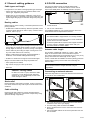
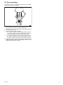
GA150 antenna
Installation instructions
English
Date: 05-2014
Document number: 87230-1-EN
© 2014 Raymarine UK Limited
Trademark and patents notice
Autohelm, hsb2, RayTech Navigator, Sail Pilot, SeaTalk, SeaTalkNG, SeaTalkHS and Sportpilot are registered trademarks of
Raymarine UK Limited. RayTalk, Seahawk, Smartpilot, Pathfinder and Raymarine are registered trademarks of Raymarine
Holdings Limited.
FLIR is a registered trademark of FLIR Systems, Inc. and/or its subsidiaries.
All other trademarks, trade names, or company names referenced herein are used for identification only and are the property
of their respective owners.
This product is protected by patents, design patents, patents pending, or design patents pending.
Fair Use Statement
You may print no more than three copies of this manual for your own use. You may not make any further copies or distribute or use
the manual in any other way including without limitation exploiting the manual commercially or giving or selling copies to third parties.
Software updates
Check the website www.raymarine.com for the latest software releases for your product.
Product handbooks
The latest versions of all English and translated handbooks are available to download in PDF format from the website www.raymarine.com.
Please check the website to ensure you have the latest handbooks.
Copyright ©2014 Raymarine UK Ltd. All rights reserved.
ENGLISH
Document number: 87230-1
Date: 05-2014
Contents
Chapter 1 Important information........................ 7
Certified Installation ................................................... 7
Water ingress ............................................................ 7
Disclaimer ................................................................. 7
EMC installation guidelines ........................................ 7
Suppression ferrites ................................................... 7
Connections to other equipment ................................. 7
Declaration of conformity............................................ 7
Product disposal ........................................................ 7
Warranty registration.................................................. 8
IMO and SOLAS........................................................ 8
Technical accuracy .................................................... 8
Chapter 2 Document and product
information........................................................... 9
2.1 Document information .......................................... 10
2.2 GA150 Parts supplied........................................... 10
2.3 GA150 product overview ...................................... 11
Chapter 3 Planning the installation ................... 13
3.1 Installation checklist ............................................. 14
3.2 GA150 MFD compatibility ..................................... 14
3.3 Tools required ...................................................... 15
3.4 Warnings and cautions ......................................... 15
3.5 Antenna location requirements.............................. 16
3.6 Product dimensions.............................................. 16
Chapter 4 Cables and connections.................... 17
4.1 General cabling guidance ..................................... 18
4.2 GA150 connection................................................ 18
Chapter 5 Mounting............................................. 19
5.1 Fitting the antenna ............................................... 20
5.2 Surface mounting................................................. 20
5.3 Pole mounting...................................................... 21
Chapter 6 System checks and
troubleshooting ................................................... 23
6.1 Further information............................................... 24
6.2 Troubleshooting ................................................... 25
Chapter 7 Maintenance ....................................... 27
7.1 Routine checks .................................................... 28
7.2 Unit cleaning instructions ...................................... 28
Chapter 8 Technical support .............................. 29
8.1 Raymarine customer support ................................ 30
Chapter 9 Technical specification...................... 31
9.1 Technical specification.......................................... 32
5
6
GA150
Chapter 1: Important information
Certified Installation
Raymarine recommends certified installation by a Raymarine
approved installer. A certified installation qualifies for enhanced
product warranty benefits. Contact your Raymarine dealer for
further details, and refer to the separate warranty document
packed with your product.
Warning: Product installation and
operation
This product must be installed and operated in
accordance with the instructions provided. Failure
to do so could result in personal injury, damage to
your vessel and/or poor product performance.
Warning: Potential ignition source
This product is NOT approved for use in
hazardous/flammable atmospheres. Do NOT install
in a hazardous/flammable atmosphere (such as in
an engine room or near fuel tanks).
Warning: Switch off power supply
Ensure the vessel’s power supply is switched OFF
before starting to install this product. Do NOT
connect or disconnect equipment with the power
switched on, unless instructed in this document.
Note: In areas of extreme EMC interference, some slight
interference may be noticed on the product. Where this occurs
the product and the source of the interference should be
separated by a greater distance.
For optimum EMC performance we recommend that wherever
possible:
• Raymarine equipment and cables connected to it are:
– At least 1 m (3 ft) from any equipment transmitting or
cables carrying radio signals e.g. VHF radios, cables and
antennas. In the case of SSB radios, the distance should
be increased to 7 ft (2 m).
– More than 2 m (7 ft) from the path of a radar beam. A
radar beam can normally be assumed to spread 20 degrees
above and below the radiating element.
• The product is supplied from a separate battery from that used
for engine start. This is important to prevent erratic behavior
and data loss which can occur if the engine start does not
have a separate battery.
• Raymarine specified cables are used.
• Cables are not cut or extended, unless doing so is detailed in
the installation manual.
Note: Where constraints on the installation prevent
any of the above recommendations, always ensure the
maximum possible separation between different items of
electrical equipment, to provide the best conditions for EMC
performance throughout the installation
Suppression ferrites
Caution: Service and maintenance
This product contains no user serviceable
components. Please refer all maintenance
and repair to authorized Raymarine dealers.
Unauthorized repair may affect your warranty.
Raymarine cables may be fitted with suppression ferrites. These
are important for correct EMC performance. If a ferrite has to be
removed for any purpose (e.g. installation or maintenance), it
must be replaced in the original position before the product is
used.
Use only ferrites of the correct type, supplied by Raymarine
authorized dealers.
Water ingress
Water ingress disclaimer
Although the waterproof rating capacity of this product meets
the stated IPX standard (refer to the product’s Technical
Specification), water intrusion and subsequent equipment
failure may occur if the product is subjected to commercial
high-pressure washing. Raymarine will not warrant products
subjected to high-pressure washing.
Disclaimer
Raymarine does not warrant that this product is error-free or that
it is compatible with products manufactured by any person or
entity other than Raymarine.
Where an installation requires multiple ferrites to be added to a
cable, additional cable clips should be used to prevent stress on
the connectors due to the extra weight of the cable.
Connections to other equipment
Requirement for ferrites on non-Raymarine cables
If your Raymarine equipment is to be connected to other
equipment using a cable not supplied by Raymarine, a
suppression ferrite MUST always be attached to the cable near
the Raymarine unit.
Declaration of conformity
Raymarine UK Ltd. declares that this product is compliant with
the essential requirements of R&TTE directive 1999/5/EC.
Raymarine is not responsible for damages or injuries caused by
your use or inability to use the product, by the interaction of the
product with products manufactured by others, or by errors in
information utilized by the product supplied by third parties.
The original Declaration of Conformity certificate may be viewed
on the relevant product page at www.raymarine.com.
EMC installation guidelines
Product disposal
Raymarine equipment and accessories conform to the
appropriate Electromagnetic Compatibility (EMC) regulations,
to minimize electromagnetic interference between equipment
and minimize the effect such interference could have on the
performance of your system
Dispose of this product in accordance with the WEEE Directive.
Correct installation is required to ensure that EMC performance
is not compromised.
Important information
The Waste Electrical and Electronic Equipment (WEEE)
Directive requires the recycling of waste electrical and electronic
equipment. Whilst the WEEE Directive does not apply to some
Raymarine products, we support its policy and ask you to be
aware of how to dispose of this product.
7
Warranty registration
To register your Raymarine product ownership, please visit
www.raymarine.com and register online.
It is important that you register your product to receive full
warranty benefits. Your unit package includes a bar code label
indicating the serial number of the unit. You will need this serial
number when registering your product online. You should retain
the label for future reference.
IMO and SOLAS
The equipment described within this document is intended for
use on leisure marine boats and workboats NOT covered by
International Maritime Organization (IMO) and Safety of Life at
Sea (SOLAS) Carriage Regulations.
Technical accuracy
To the best of our knowledge, the information in this document
was correct at the time it was produced. However, Raymarine
cannot accept liability for any inaccuracies or omissions it
may contain. In addition, our policy of continuous product
improvement may change specifications without notice. As a
result, Raymarine cannot accept liability for any differences
between the product and this document. Please check the
Raymarine website (www.raymarine.com) to ensure you have
the most up-to-date version(s) of the documentation for your
product.
8
GA150
Chapter 2: Document and product information
Chapter contents
•
2.1 Document information on page 10
•
2.2 GA150 Parts supplied on page 10
•
2.3 GA150 product overview on page 11
Document and product information
9
2.1 Document information
2.2 GA150 Parts supplied
This document contains important information related to the
installation of your Raymarine product.
The parts supplied with your GA150 GNSS (GPS / GLONASS)
antenna are shown below.
The document includes information to help you:
• plan your installation and ensure you have all the necessary
equipment;
• install and connect your product as part of a wider system of
connected marine electronics;
1
4
2
5
3
6
7
• troubleshoot problems and obtain technical support if required.
This and other Raymarine product documents are available to
download in PDF format from www.raymarine.com.
D13075-1
Applicable products
This document is applicable to the following products:
1. GA150 antenna (The antenna is supplied with a fitted 10 m
(33 ft.) cable for connection to your MFD.)
Part number
Name
Description
2. GA150 mounting gasket
A80288
GA150
GNSS (GPS
/ GLONASS)
antenna
3. Pole mount adaptor
4. 2 x Thumbs nuts
5. 2 x Studs
6. 2 x screws
Document illustrations
7. Document pack
Your product may differ slightly from that shown in the
illustrations in this document, depending on product variant and
date of manufacture.
All images are provided for illustration purposes only.
Product documentation
The following documentation is applicable to your product:
Description
Part number
GA150 Installation instructions
Installation of a GA150 antenna and connection to a
compatible MFD.
87230 / 88038
GA150 Surface mount template
Mounting diagram for surface mounting a GA150.
87224
10
GA150
2.3 GA150 product overview
The GA150 is an external antenna capable of improving the
reception of a Multifunction display’s (MFD’s) internal Global
Navigation Satellite System (GNSS) receiver.
D13078-1
The GA150 has the following features:
• 10 m (33 ft.) fitted cable.
• Low power consumption.
• Surface or pole mountable.
Note: When the Beidou GNSS becomes available a GA150
MUST be used in order to obtain reception. Your MFD will
also require a software update to enable support of the Beidou
system.
Document and product information
11
12
GA150
Chapter 3: Planning the installation
Chapter contents
•
3.1 Installation checklist on page 14
•
3.2 GA150 MFD compatibility on page 14
•
3.3 Tools required on page 15
•
3.4 Warnings and cautions on page 15
•
3.5 Antenna location requirements on page 16
•
3.6 Product dimensions on page 16
Planning the installation
13
3.1 Installation checklist
3.2 GA150 MFD compatibility
Installation includes the following activities:
The GA150 antenna is compatible with the following Raymarine
variant MFDs:
Installation Task
• a95 / a97 / a98
1
Plan your system.
2
Obtain all required equipment and tools.
3
Site all equipment.
Multifunction display software requirements
4
Route all cables.
5
Drill cable and mounting holes.
The operation of this product requires that your Raymarine MFD
is running LightHouse II software Release 11 or later.
6
Make all connections into equipment.
7
Secure all equipment in place.
8
Power on and test the system.
• a125 / a127 / a128
Schematic diagram
A schematic diagram is an essential part of planning any
installation. It is also useful for any future additions or
maintenance of the system. The diagram should include:
• Location of all components.
• Connectors, cable types, routes and lengths.
14
GA150
3.3 Tools required
3.4 Warnings and cautions
Product installation requires the following tools:
Item
Description
Quantity
Power drill
1
Pozidrive screwdriver
1
Drill bit of appropriate size*
1
Adhesive tape
1
Important: Before proceeding, ensure that you have read
and understood the warnings and cautions provided in the
Chapter 1 Important information section of this document.
Note: * The appropriate drill bit size is dependent on the
thickness and material of the mounting surface.
Planning the installation
15
The antenna can be mounted either on a flat horizontal surface
or on a suitable pole.
• If you intend to surface mount the antenna, ensure you have
access to the underside of the mounting surface.
• If you intend to pole-mount the antenna, the pole needs to
have a 1 inch 14 TPI thread.
95 mm (3.7 in.)
30 mm (1.2 in.)
The antenna can be used to improve the reception of your
MFD’s built-in GNSS (GPS / GLONASS) receiver. Do NOT
connect any other antenna to the MFD’s GA150 connector.
3.6 Product dimensions
32 mm (1.3 in.)
3.5 Antenna location requirements
D13077-1
Important: The antenna must be mounted in a location that
provides a good direct line of site to the entire sky, around
the horizon.
Ensure that the selected mounting location is:
• Open and clear of any obstructions (such as masts, search
lights, or other structures) that could block line-of-sight to the
sky.
• As low as possible, to keep the antenna as stable as possible.
The more stable the antenna, the more effectively it will track
satellites and provide stable data.
• As far as possible (at least 1 m (3 ft) from other antennae and
electronic equipment.
Do NOT mount the antenna:
• In any area where it could be stepped on or tripped over.
• Up a mast. This will cause the antenna to swing and give
significant errors in position data.
• In the direct path of a radar beam.
Antenna Mounting & EME Exposure
For optimal radio performance and minimal human exposure to
radio frequency electromagnetic energy, make sure the antenna
is:
• connected to the radio before transmitting
• properly mounted
• located where it will be away from people
• located at least 1.5 metres (5 feet) from the radio’s main unit
16
GA150
Chapter 4: Cables and connections
Chapter contents
•
4.1 General cabling guidance on page 18
•
4.2 GA150 connection on page 18
Cables and connections
17
4.1 General cabling guidance
4.2 GA150 connection
Cable types and length
a9x and a12x MFDs include an internal GNSS (GPS /
GLONASS) receiver. The GA150 antenna can be used to
improve the GNSS (GPS / GLONASS) receiver’s reception.
It is important to use cables of the appropriate type and length
• Unless otherwise stated use only standard cables of the
correct type, supplied by Raymarine.
1
2
• Ensure that any non-Raymarine cables are of the correct
quality and gauge. For example, longer power cable runs may
require larger wire gauges to minimize voltage drop along the
run.
Routing cables
D13069-1
Cables must be routed correctly, to maximize performance and
prolong cable life.
• Do NOT bend cables excessively. Wherever possible, ensure
a minimum bend diameter of 200 mm (8 in) / minimum bend
radius of 100 mm (4 in).
1. GA150 antenna
2. a9x or a12x variant MFD
For installation details for your external antenna, refer to the
documentation that accompanied the antenna.
Note:
200 mm (8 in)
• The Beidou GNSS is supported but not currently available.
100 mm (4 in)
• Protect all cables from physical damage and exposure to heat.
Use trunking or conduit where possible. Do NOT run cables
through bilges or doorways, or close to moving or hot objects.
• Secure cables in place using tie-wraps or lacing twine. Coil
any extra cable and tie it out of the way.
• Where a cable passes through an exposed bulkhead or
deckhead, use a suitable watertight feed-through.
• Do NOT run cables near to engines or fluorescent lights.
Always route data cables as far away as possible from:
• other equipment and cables,
• high current carrying ac and dc power lines,
• antennae.
Caution: Pulling cables
Do NOT use cords or ropes, attached to cable
connectors, to pull cables through restricted
apertures (e.g. as in bulkheads), as this could
cause damage to cables.
• A GA150 must be connected in order to receive the Beidou
system when it becomes available.
• A software update will be required to add support for Beidou
once the system is available. Please check with your
Raymarine dealer for further details.
Antenna cable length
The GA150 is supplied with a fitted 10 m (33 ft.) cable. The
length of the antenna cable can be extended if required.
The antenna cable length can be extended by up to 10 m (33 ft.)
giving a total maximum cable length of 20 m (66 ft.)
50 ohm coaxial cable and reliable connectors (offering protection
against water ingress) must be used when extending the
antenna cable.
Note: Extending the cable length by more than the
recommended maximum length will result in signal
degradation.
Connecting an external antenna
Follow the steps below to connect the GA150 external antenna
to your a9x or a12x variant MFD.
1
2
3
4
Strain relief
Ensure adequate strain relief is provided. Protect connectors
from strain and ensure they will not pull out under extreme sea
conditions.
Cable shielding
Ensure that all data cables are properly shielded that the
cable shielding is intact (e.g. hasn’t been scraped off by being
squeezed through a tight area).
D13074-1
1. Fully insert the antenna’s cable connector into the GA150
connector on the rear of your display.
2. Turn the locking collar clockwise until TIGHT.
3. Push to protective boot over the connection on the back of
the display.
4. Use the supplied cable tie to secure the protective boot over
the connection.
18
GA150
Chapter 5: Mounting
Chapter contents
•
5.1 Fitting the antenna on page 20
•
5.2 Surface mounting on page 20
•
5.3 Pole mounting on page 21
Mounting
19
5.1 Fitting the antenna
5.2 Surface mounting
To fit the antenna:
1. Select a suitable location for the antenna as described under
Antenna location requirements.
2. Fit your antenna using either the Surface mounting or Pole
mounting procedure, as appropriate.
3. Ensuring that cable routing and connection requirements as
detailed in the installation instructions for the product that the
antenna will be connected to are followed.
When surface mounting the antenna, you can route the cable
either centrally (Option A) or from the side of the antenna
(Option B).
1. Use the template supplied to mark the two 6 mm (0.25 in)
mounting holes.
• OPTION A: If the cable is going to pass through the
mounting surface drill a 19 mm (0.75 in) center hole.
• OPTION B: If the cable is to be routed from the side of the
antenna (i.e. above the mounting surface), remove the
two plastic tabs (1) obstructing the cable channel. If you
do not remove these tabs before using the cable channel,
you could damage the cable.
2
B
3
2
4
4
Top view
Underside view
1
3
D11638-1
A
2. Screw the two mounting studs (2) into the underside of the
antenna.
3. Stick the supplied gasket (3) to the mounting surface,
ensuring that the holes on the gasket correspond with the
drilled holes.
4. Route the cable as follows:
• For Option A, feed the cable down through the center hole.
• For Option B, route the cable along the cable exit channel.
5. Carefully place the antenna so the mounting studs pass
through the holes in the mounting surface.
6. Secure the antenna to the surface using the supplied thumb
nuts (4).
20
GA150
5.3 Pole mounting
If you want to pole-mount the antenna, obtain a pole of suitable
length with a 1 inch 14 TPI thread.
A
B
D13076-1
1. Ensuring that the Antenna location requirements are met,
securely attach the pole to a suitable, stable point.
2. Screw the pole mount adaptor fully onto the pole and ensure
it is secure on the pole.
3. Route the antenna cable as follows:
i. If you want to route the antenna cable directly down from
the antenna (option A), feed it through the center of the
pole mount adaptor and then down through the pole.
ii. If you want to route the antenna cable out of the side of
the antenna (option B), remove the two plastic tabs from
the cable channel, then feed the cable along the channel.
4. Ensuring you do not trap the cable, place the antenna on the
pole mount adaptor so the screw holes align, then secure the
antenna with the screws provided.
Mounting
21
22
GA150
Chapter 6: System checks and troubleshooting
Chapter contents
•
6.1 Further information on page 24
•
6.2 Troubleshooting on page 25
System checks and troubleshooting
23
6.1 Further information
For detailed operating instructions, refer to the handbook that
accompanies your display.
24
GA150
6.2 Troubleshooting
The troubleshooting information provides possible causes and
corrective action required for common problems associated with
marine electronics installations.
All Raymarine products are, prior to packing and shipping,
subjected to comprehensive test and quality assurance
programs. However, if you experience problems with the
operation of your product this section will help you to diagnose
and correct problems in order to restore normal operation.
If after referring to this section you are still having problems
with your unit, please contact Raymarine Technical Support for
further advice.
System checks and troubleshooting
25
GPS troubleshooting
Problems with the GPS and their possible causes and solutions are described here.
Problem
Possible causes
Possible solutions
“No Fix” GPS status icon is displayed.
Geographic location or prevailing
conditions preventing satellite fix.
Check periodically to see if a fix is obtained in better conditions or
another geographic location.
GPS connection fault.
Ensure that external GPS connections and cabling are correct and fault
free.
External GPS antenna in poor position.
For example:
Ensure GPS antenna has a clear view of the sky.
• Below decks.
• Close proximity to transmitting
equipment such as VHF radio.
GPS installation problem.
Refer to the installation instructions.
Note: A GPS Status screen is available within the display. This provides satellite signal strength and other relevant information.
26
GA150
Chapter 7: Maintenance
Chapter contents
•
7.1 Routine checks on page 28
•
7.2 Unit cleaning instructions on page 28
Maintenance
27
7.1 Routine checks
7.2 Unit cleaning instructions
The following periodic checks should be made:
The unit does not require regular cleaning. However, if you find
it necessary to clean the unit, please follow the steps below:
1. Ensure power is switched off.
2. Wipe unit clean with a damp cloth.
3. If necessary, use a mild detergent solution to remove grease
marks.
• Examine cables for signs of damage, such as chafing, cuts or
nicks.
• Check that the cable connectors are firmly attached and that
their locking mechanisms are properly engaged.
Note: Cable checks should be carried out with the power
supply switched off.
28
GA150
Chapter 8: Technical support
Chapter contents
•
8.1 Raymarine customer support on page 30
Technical support
29
8.1 Raymarine customer support
Raymarine provides a comprehensive customer support service.
You can contact customer support through the Raymarine
website, telephone and e-mail. If you are unable to resolve a
problem, please use any of these facilities to obtain additional
help.
Web support
Please visit the customer support area of our website at:
www.raymarine.com
This contains Frequently Asked Questions, servicing information,
e-mail access to the Raymarine Technical Support Department
and details of worldwide Raymarine agents.
Telephone and e-mail support
In the USA:
• Tel: +1 603 324 7900
• Toll Free: +1 800 539 5539
• E-mail: [email protected]
In the UK, Europe, and the Middle East:
• Tel: +44 (0)13 2924 6777
• E-mail: [email protected]
In Southeast Asia and Australia:
• Tel: +61 (0)29479 4800
• E-mail: [email protected]
Product information
If you need to request service, please have the following
information to hand:
• Product name.
• Product identity.
• Serial number.
• Software application version.
• System diagrams.
You can obtain this product information using the menus within
your product.
30
GA150
Chapter 9: Technical specification
Chapter contents
•
9.1 Technical specification on page 32
Technical specification
31
9.1 Technical specification
Physical specification
Dimensions
• Diameter: 95 mm (3.7 in.)
• Height: 30 mm (1.2 in.)
• Height (including pole mount
adaptor): 62 mm (2.5 in.)
Weight
• Boxed weight 0.74 Kg (1.6 lbs)
• Unboxed weight (including
cable): 0.5 Kg (1.1 lbs)
Environmental specification
Operating temperature
0°C to +55°C (+32°F to +131°F)
Storage temperature
–30°C to +70°C (-22°F to +158°F)
Relative humidity
95%
Waterproof rating
IPX6 and IPX7
Conformance specification
Conformance
• EN 60945:2002
• R&TTE Directive 1999/5/EC
• Australia and New Zealand:
C-Tick, Compliance Level 2
32
GA150
www.ra ym a rin e .c o m