1
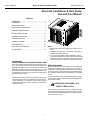
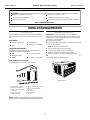
Service Questions: Contact Comfort Aire at (517) 787-2100 Sales Inquiries: Contact Sylvane at (800) 934-9194 or visit sylvane.com OWNER’S MANUAL Room Air Heat Pump with R-410A: RAH-123G Heat Controller, Inc. • 1900 Wellworth Ave. • Jackson, MI 49203 • (517)787-2100 • www.heatcontroller.com Room Air Heat Pump with R-410A Owner’s Manual Heat Controller, Inc. Room Air Conditioner & Heat Pump Use and Care Manual Contents Introduction............................................................. .................................................................. 11 Introduction. SafetyInformation................................................... Information ....................................................... 11 Safety NormalCare Care && Maintenance................................... Maintenance ......................................33 Normal Installation Requirements ........................................... 5 Installation Requirements........................................ 5 + R ME /TI - MP Set Electrical Requirements .............................................. 6 R WE PO Electrical Requirements.......................................... 6 O AUTH HIG d ME LOW T ER HEA OL Y SAV CO RG LY ENE ON TE ER HR TIM4 1-2 FAN dE MO Nd FAEE SP Installation Instructions ............................................... 8 Installation Instructions............................................ 8 Through-The -Wall Cabinet Instructions .....................10 General Instructions...............................................11 Complete Instructions ...............................................12 Operating Controls................................................ 12 General Instructions .................................................. 13 Troubleshooting..................................................... 14 Operating Controls .................................................... 14 When Service is Required..................................... 14 Before Calling Services...............................................17 Any Questions....................................................... 14 When Service Is Required.... ...................................... 17 Any Questions? ........................................................... 17 Through-The -Wall Installations Instructions ............ 18 Introduction Room Room air air conditioners conditioners cool, cool,dehumidify, dehumidify and filter filter air air inside inside your Heat pump pump models and electric both your home. home. Heat offerheat bothmodels heatingoffer and coolheating cooling. Opening sections of manual provide ing. Theand opening sections of this manual provides some general information air air conditioner models. The general informationfor forallallroom room conditioner models. Operating Controls Controls section section describes describes operation operation of of controls controls Operating for each each model. model. After reading the opening opening sections, sections, turn turn to to for the Operating Controls section findpanel the panel Operating Controls section and and find the layoutlayout that that matches your model. matches the model of your unit. Read entire manual thoroughly before beginning installation and operation of your new room air conditioner. Be sure you have all necessary tools and materials on hand for the job. Study illustrations to familiarize yourself with important details of the installation process. Review manual for operating instructions. NOTE 1. Mechanical experience is required to install air conditioner. 2. Installation can take from 1 to 3 hours, depending on installer’s knowledge and skill. 3. If you you encounter encounter problems problemsduring duringinstallation, installation,call callour our 8617555. consumer information informationline lineat at(86-756) (517) 787-2100 and ask for If your problem cannot be resolved by phone, contact an the technical service deparment. If your problem cannot ® brand servicer. Contact and service authorized be resolvedGREE by phone, contact an authorized servicer. will be at your expense. Safety Information Be sure electrical service is adequate for chosen model of air conditioner. Complete electrical rating for unit is found on serial plate located behind front grille. Electrical outlet must be close enough to unit for power cord to reach without strain. Air conditioner should be the only appliance on individual circuit. For personal safety and to avoid possible damage to appliance or home, observe all safety instructions highlighted by symbol shown below. RECOGNIZE THIS SYMBOL AS A SAFETY PRECAUTION. After installing unit, reread instructions to ensure each step is complete and that all parts are fastened in place. For best results and to minimize installation time, perform all procedures in the order shown. 1 1 Heat Controller, Inc. Room Air Heat Pump with R-410A Owner’s Manual OWNER'S PRODUCT IDENTIFICATION WARNING To preventheat heatrelated related illness or death, do To prevent illness or death, not useuse this device unattended cooling do not this devicefor unattended. Failure of anor unattended air conditioner of persons animals unable to react to may result in extreme heatof inunattended area product failure. Failure air intended for cooling, causing heat related conditioner may result in extreme heat in illness or deathfor of persons animals.heatarea intended cooling,orcausing related illness or death of persons or animals. MOdEL NUMBER SERIAL NUMBER MANUFACTURING NUMBER Owner's Name Address City WARNING State / Zip / date of Purchase HIGH TEMPERATURE STRESS HAZARD This room air conditioner is not meant to provide unattended cooling or life support for persons or animals that are unable to react to failure of the product. Authorized dealer Address City ( The failure of an unattended air conditioner may result in extreme heat in the conditioned space causing overheating or death of persons or animals. State Zip ) Phone Number WARNING To avoid death, personal injury or property damage due to electrical shock: Precautions must be taken to ward off or guard against such an occurrence. • • • • Unpacking Unpackand andvisually visually inspect unit. Report any damage to Unpack inspect thethe unit. Report any damage to the delivering carrier immediately. Remove and discard all the delivering carrier immediately. If your unit is not damaged, packingand material. remove disgard all packing materials. • • WARNING • Do NOT operate unit with shipping foam blocks in place. Always remove prior to running unit. • On some models the air conditioner front and/or mounting kit hardware may be packed separately. Record themodel model, serial and manufacturing numbers of your Record the and serial numbers of your unit in the space provided. information found on a nameplate visible afteron unit in theThis space providedisbelow. This information is found the front of thevisible air conditioner has been The rated has a nameplate after the front ofremoved. the air conditioner voltage, amperage and capacity for your specificand model can for been removed. The rated voltage, amperage capacity also be found on this nameplate. the warranty your specific model can also Read be found on this packaged nameplate. with the unit. Register your unit with and keep the warranty a Read the warranty packaged the unit. Keep theand warranty copyaofcopy yourofsales for future You may You also may and yourreceipt sales receipt forreference. future reference. want want to record in the in space provided the datethe purchased and also to record the space provided date purchased the selling dealer.dealer. and the selling • • • • Observe all local codes and ordinances. disconnect electrical power to unit before servicing. Ground appliance properly. Check with a qualified electrician if you are not sure this appliance is properly grounded. dO NOT ground to gas line. dO NOT ground to cold water pipe if pipe is interrupted by plastic, non-metallic gaskets, or other insulating (non-conducting) materials. dO NOT modify plug on power cord. If plug does not fit electrical outlet, have proper outlet installed by qualified electrician. dO NOT have a fuse in the neutral or ground circuit. A fuse in the neutral or ground circuit could result in an electrical shock. dO NOT use an extension cord with this appliance. dO NOT use an adapter plug with this appliance. dO NOT pinch power cord. dO NOT REMOVE warning tag from power cord. Electrical Requirements Grounding Instructions This appliance is equipped with a three-prong grounding plug for protection against possible shock hazards. If a two-prong 2 2 Room Air Heat Pump with R-410A Owner’s Manual Unit Plug Type Receptacle Required page included with this manual or in the mounting kit assembly. Follow these instructions carefully. Keep these instructions with this manual for future reference. Your unit will be one of the following three designs: Circuit Rating, Voltage Breaker, Time Rating On Delay Fuse Nameplate NEMA No. 5-15P NEMA No. 5-15R 125V-15AMP 115V NEMA No. 6-15P NEMA No. 6-15R 250V-15AMP 230/208V rated at 12 amperes or less NEMA No. 6-20P NEMA No. 6-20R 250V-20AMP 230/208V rated over 12 amperes, but not more than 16 amperes NEMA No. 6-30P NEMA No. 6-30R 250V-30AMP 208V rated over 16 amperes, but not more than 24 amperes • • Unit with a window mounting kit These models are designed for mounting though an opening in a wall. These units can be adapted to window installation by using the optional window mounting kit supplied with your unit. Unit without a window mounting kit No window mounting kit is supplied with the unit. These models are designed for mounting through an opening in a wall. These units can be adapted to window installation by purchasing an optional window mounting kit. Consult your dealer to choose the kit that is appropriate for your model and installation. Room Heat Pumps Heat pumps work by moving heat instead of creating it. In the summer, the cool indoor coil absorbs heat from your room and moves it outdoors, providing cooling. In the winter, heat pumps reverse this operation. By lowering the temperature of the outdoor coil below the outdoor temperature, the heat pump absorbs the heat from outdoors and moves it inside your house. This heat transferring process is very efficient. For example, at 45°F outdoor temperature, a heat pump can provide 2 ½ watts of heat for every watt of electricity it consumes. wall receptacle is encountered, the customer is required to contact a qualified electrician and have the two-prong wall receptacle replaced with a properly grounded three-prong wall receptacle in accordance with the National Electrical Code. Room air conditioners are designed to operate according to requirements on the nameplate and as shown in Table 1. Fuse or circuit breaker ratings must be according to the fuse instruction label and as shown in Table 1. do not plug models marked “Use on Single Outlet Circuit Only” into a circuit with another appliance or light fixture. As outdoor temperatures drop, the heating capacity and efficiency of the heat pump declines. At temperatures below 45°F, it is likely that ice will form on the outdoor coil. Heat pump units are designed to operate as a heat pump above approximately 40°F. Below 40°F, these units switch automatically from reverse cycle heat pump to auxiliary electric heating. No defrost is required. There is no minimum operating temperature. Receptacle Wiring Receptacle wiring must be of adequate size for unit. Refer to unit identification plate for exact power requirements. Minimum size of wiring, based on power requirements, is: Units up to 20 amps: 20–30 amp units: Heat Controller, Inc. 12 gauge 10 gauge Normal Care and Maintenance LCDI or AFCI Power Cords Underwriters Laboratories (UL) andand the the National Electric Code Underwriters Laboratories (UL) National Electric (NEC) (NEC) now require power cords thatcords sensethat current leakage to Code now require power sense current be able toand open the electrical circuit to circuit the unit.toInthe theunit. event, leakage can open the electrical In the unit does operate, the reset check button located on or near event, thenotunit doescheck not operate, the reset button the headon of or thenear power as of part of power the normal located thecord head the cordtroubleshooting as part of the procedure. normal troubleshooting procedure. WARNING CAUTION Installing an air conditioner through a wall To avoid property damage, personal injury or death due to electrical shock,and/or turn unit requires extensive carpentry masonOFF and remove plug frominstallations wall outlet before ry experience. Thru-wall perinspecting unit or performing maintenance. formed by inexperienced or unqualified individuals can result in costly damage to home. Use copper wire only. Consumer’s responsibility is to provide proper and adequate receptacle wiring that conforms to all applicable codes. All wiring should be installed by qualified electrician. Annual Inspection It is suggested that your unit be inspected by your dealer or servicer once a year. It is advisable to have the outer case removed and the unit thoroughly cleaned. Installation Complete step-by-step installation instructions are furnished with your unit. These instructions will be found on a separate 3 3 Room Air Heat Pump with R-410A Heat Controller, Inc. Note: greatly reduced Note: The Thelife lifeof of your your unit unit may may be be greatly reducedifif you you live live in corrosive and/or oceanside location with salty air. Under in aasalt air or other corrosive type environment. Under these these conditions, the should unit should be removed its case conditions, the unit be removed fromfrom its case and and completely cleaned least oncea ayear. year. At At that that time time any completely cleaned at at least once any scratches on on the the painted surfaces should should be sanded scratchesororblisters blisters painted surfaces be and repainted. Placing an Placing algaecideantablet in the tablet outdoorinside sanded and repainted. algaecide the of the unit’s basepan suggested in humid areas where algae outdoor side of the is unit’s basepan is suggested in humid formation is common. areas where algae formation is common. Air Filter Cleaning A dirty air filter reduces operating efficiency of unit. Filter should be inspected at least once every week during operation. Clean filter with vacuum cleaner or wash in warm water and mild detergent. Filter should be thoroughly dried before replacing in unit. do not operate unit without filter in place. Fan Motor Care The fan motor is permanently lubricated for long life. There is no need to oil the motor. Front Grille and Filter Removal Slide-out Chassis Removal from Outer Case 4. If the unit has a screw holding the basepan clip to the chassis, remove the screw. The front contains an air filter that can be removed on left or right side of front. To clean the filter use one of the following methods for filter removal: CAUTION METHOD ONE Grasp filter handle and slide filter out of unit. + To personal injury, be be To reduce reducethe therisk riskofof personal injury sure help when moving sure to tohave havesufficient sufficient help when moving your the air weight of your unit your unit. unit.Check A room conditioner canby contacting your dealer. weigh between 70 and 240 pounds. 5. Using basepan handle, pull chassis straight out, slowly and evenly, until approximately 9-12 inches extends from outer case. Use both hands to grasp basepan and pull remaining chassis from outer case. R IME P/T O AUT T HEA L LOW TEM ER HR TIM 1-24 ER SAV COORGY Y ENE ONL FAN HIGH MEd - Set ER POW Owner’s Manual dE MO FANEd SPE 1. Remove two side ground screws attaching case to chassis basepan. 2. Remove two control knobs. 3. Remove two side Phillips screws attaching front panel to case. CHASSIS P/T T HEA L SAVE COORGY Y ENE ONL LOW R TEM ER HR TIM 1-24 FAN HIGH MEd - O AUT PLASTIC FRONT NOTE: Basepan clip is shipped in plastic bag with mounting screw and condensate drain cup. Install clip after reinserting chassis into outer case to prevent accidental chassis removal. + IMER Set ER POW BASEPAN CLIP dE MO FANEd SPE Reinstall air filter by reversing removal procedure. Front Grille and Cabinet Cleaning Grille and cabinet may be cleaned with warm water and mild soap or detergent. Cleaning and polishing compounds are not recommended, as they may damage plastic surfaces. 4 4 Room Air Heat Pump with R-410A Owner’s Manual Heat Controller, Inc. IMPORTANT SAFETY INSTRUCTIONS WARNING: To reduce the risk of fire, electrical shock or injury when using your air conditioner, follow these basic precautions: Plug into a grounded 3 prong outlet. Do not use an extension cord. Do not remove ground prong. Unplug air conditioner before servicing. Do not use an adapter. Use two or more people to move and install air conditioner. SAVE THESE INSTRUCTIONS INSTALLATION REQUIREMENTS Tools and Parts Location Requirements IMPORTANT: Observe all governing codes and ordinances. Check the location where air conditioner will be installed. Proper installation is your responsibility. Make sure you have everything necessary for correct installation. The location should provide: ■ Grounded electrical outlet within 4 ft of where the power cord exits the air conditioner. Gather the required tools and parts before starting installation. Read and follow the instructions provided with any tools listed here. Tools Needed ■ ■ Flat-head Flat-blade and Phillips screwdrivers ■ Tape measure ■ Drill and ³⁄₁₆" or smaller bit Level NOTE: Do not use an extension cord. Free movement of air in room to be cooled. Through-the-wall installation: ■ In addition to the tools listed above, the following tools are needed for though-the-wall installation. ■ A large enough opening for the air conditioner. ■ Adequate Adequate wall wall support supportfor forweight weightofofair airconditioner. conditioner. Air conditioner weighs 103 lbsyour . Check the weight of between your unit 94 by and contacting dealer. ■ Saw ■ Wood preservative ■ Caulk ■ 1" or thicker lumber ■ 7 - #10 x 1" wood screws NOTE: Cabinet louvers must not be obstructed. Air must be able to pass freely through the cabinet louvers. A Parts supplied (on some models) Check that all parts are included in parts package. B A H C d E F G A. Cabinet louvers I A. Foam window sash seal B. Window lock brackets (2) C. #10 x ¹⁄₄" pan-head Phillips screws (6) D. #10 x ³⁄₈" pan-head Phillips screws (3) E. #10 x ³⁄₄" round-head screws (6) F. #10 x 1/2" pan-head Phillips screws (3) G. Top channel H. Side curtains (2) I. Foam seal NOTE: Installation parts are supplied for double-hung windows . up to 40" wide. A special Wide Window Kit is available from your dealer or service center. See “Accessories.” 5 5 Room Air Heat Pump with R-410A Heat Controller, Inc. Owner’s Manual Electrical Requirements Window installation Window opening measurements: ■ 27" min. to 39" max. opening width. ■ WARNING 16¹⁄₄" min. opening height. Electrical Shock Hazard Plug into a grounded 3 prong outlet. A Do not remove ground prong. Do not use an adapter. B Do not use an extension cord. Failure to follow these instructions can result in death, fire, or electrical shock. A. 27" min. B. 16¹⁄₄" min. Ground wire must be connected to ground screw located in lower right corner of air conditioner when air conditioner is in cabinet. The electrical ratings for your air conditioner are listed on the model and serial number label. The model and serial number label is located behind the front panel on the flange below the control panel area. Specific electrical requirements are listed in the chart below. Follow the requirements for the type of plug on the power supply cord. Through-the-wall installation The wall opening measurements should be: ■ Height: 16" plus twice the thickness of wood used to build frame. ■ Width: 22⁵⁄₈" plus twice the thickness of wood used to build frame. Power supply cord C A B ¹⁄₄" (0.6 cm) C A. 16" B. 22⁵⁄₈" C. Wood thickness ¹⁄₂" (1.3 cm) 6 6 Wiring requirements ■ 115-volt (103.5 min. - 126.5 max.) ■ 0-12 amps ■ 15-amp time-delay fuse or circuit breaker ■ Use on single outlet circuit only. ■ 230-volt (207 min. - 253 max.) ■ 0-12 amps ■ 15-amp time-delay fuse or circuit breaker ■ Use on single outlet circuit only. ■ 208/230-volt (198min. - 253 max.) ■ 0-16 amps ■ 20-amp time-delay fuse or circuit breaker ■ Use on single outlet circuit only. ■ 230-volt (207 min. - 253 max.) ■ 0-24 amps ■ 30-amp time-delay fuse or circuit breaker ■ Use on single outlet circuit only. Room Air Heat Pump with R-410A Owner’s Manual WARNING Recommended grounding method This air conditioner must be grounded. This air conditioner is equipped with a power supply cord having a grounded 3 prong plug. To minimize possible shock hazard, the cord must be plugged into a mating, grounded 3 prong outlet, grounded in accordance with all local codes and ordinances. If a mating outlet is not available, it is the customer's responsibility to have a properly grounded 3 prong outlet installed by a qualified electrical installer. It is the customer's responsibility: ■ To contact a qualified electrical installer. ■ Electrical Shock Hazard Plug into a grounded 3 prong outlet. Do not remove ground prong. Do not use an adapter. To assure that the electrical installation is adequate and in conformance with National Electrical Code, ANSI/NFPA 70 latest edition, and all local codes and ordinances. Do not use an extension cord. Failure to follow these instructions can result in death, fire, or electrical shock. Copies of the standards listed may be obtained from: National Fire Protection Association One Batterymarch Park Quincy, MA 02269 To test your power supply cord: 1. Plug power supply cord into a grounded 3 prong outlet. 2. Press RESET. 3. Press TEST (listen for click; Reset button will trip and pop out). 4. Press and release RESET (listen for click; Reset button will latch and remain in). The power supply cord is ready for operation. NOTES: ■ The Reset button must be pushed in for proper operation. Power Supply Cord NOTE: Your unit’s device may differ from the ones shown. A B RESET TEST ■ The power supply cord must be replaced if it fails to trip when the test button is pressed or fails to reset. ■ Do not use the power supply cord as an off/on switch. The power supply cord is designed as a protective device. ■ A damaged power supply cord must be replaced with a new power supply cord obtained from the product manufacturer and must not be repaired. ■ The power supply cord contains no user serviceable parts. Opening the tamper-resistant case voids all warranty and performance claims. RESET TEST B Heat Controller, Inc. A A. Reset button B. Test button This room air conditioner is equipped with a power supply cord required by UL. This power supply cord contains state-of-the-art electronics that sense leakage current. If the cord is crushed, the electronics detect leakage current and power will be disconnected in a fraction of a second. 7 7 Room Air Heat Pump with R-410A Heat Controller, Inc. Owner’s Manual INSTALLATION INSTRUCTIONS Unpacking 3. Remove front panel by removed 2 phillips screws on both bottom left right sides of front. 3A: Remove both knobs from control panel. WARNING Excessive Weight Hazard 4. Pull on handle to slide air conditioner out of cabinet. Place air conditioner on cardboard. Use two or more people to move and install air conditioner. Failure to do so can result in back or other injury. 5. Remove any paking foam from inside of unit. Remove packaging materials ■ Remove and dispose of/recycle all packaging materials. Remove tape and glue residue from surfaces before turning on the air conditioner. Rub a small amount of liquid dish soap over the adhesive with your fingers. Wipe with warm water and dry. ■ Do not use sharp instruments, rubbing alcohol, flammable fluids, or abrasive cleaners to remove tape or glue. These products can damage the surface of your air conditioner. ■ Handle air conditioner gently. A A. Handle 1. Remove air conditioner from carton and place it on cardboard. 2. Remove shipping screws from both sides of cabinet. NOTE: Do not lift, push, pull or remove any expanded polystyrene (foam) from inside the air conditioner. It is not packing material. A A. Shipping screw NOTES: ■ Handle air conditioner gently. ■ Window Installation Window Installation (on some models) Be sure your air conditioner cabinet does not fall out of the opening during installation or removal. ■ The location where the power cord exits the air conditioner should be no more than 4 ft from a grounded 3 prong outlet. ■ Do not block the louvers on the front panel. Do not block the louvers on the outside of the air conditioner. ■ 3. Using 3 - #10 x ³⁄₈" pan-head Phillips screws, attach top channel to air conditioner cabinet. B A B B Attach Top Channel NOTE: Attach top channel and side curtains to air conditioner cabinet before placing cabinet in window. 1. Locate supplied bag of screws. 2. Place top channel on top of air conditioner cabinet, lining up the 3 holes in top channel with the 3 holes on top of air conditioner cabinet. A. Top channel B. #10 x ³⁄₈" pan-head Phillips screws (3) 8 8 Room Air Heat Pump with R-410A Owner’s Manual Attach Side Curtains Heat Controller, Inc. Attach foam adhesive seal 1. Locate provided bag of screws. 2. Insert top and then bottom of right-hand curtain housing in top and bottom curtain guides on air conditioner cabinet. Attach foam adhesive seal along the bottom of the curtain bottom channel. Back View A B A B A. Curtain housing B. Foam adhesive seal Install Cabinet into Window A. Curtain housing B. Curtain guides Bottom View A ■ Handle air conditioner gently. ■ Be sure your air conditioner cabinet does not fall out of the opening during installation or removal. ■ The location where the power cord exits the air conditioner should be no more than 4 ft from a grounded 3 prong outlet. ■ Do not block the louvers on the front panel. ■ Do not block the louvers on the outside of the air conditioner. 1. Center empty cabinet in window. Check that lower rail of air conditioner cabinet is behind and against back side of windowsill. Maintain a firm hold on the air conditioner cabinet. Lower window sash to hold cabinet in place. Top channel must be on inside room of window sash. B A. Curtain housing B. Curtain guides 3. Extend right-hand curtain outward so you may insert the first screw through the middle hole of the curtain. Using #10 x ¹⁄₄" pan-head Phillips screw, screw curtain to middle hole in air conditioner cabinet. NOTE: This screw is required to correctly attach curtain (top to bottom) to the air conditioner cabinet. Windower sash Top channell 2. Measure the distance between the right-hand side of the cabinet and the inside of the window channel. 3. Repeat for the left side. Adjust the cabinet until the distance on each side is the same. A B 4. While the right-hand curtain is still extended, insert #10 x ¹⁄₄" pan-head Phillips screws into the top and bottom slots of curtain. Screw curtain to the top and bottom holes in air conditioner cabinet. NOTE: Some curtains may have 2 slots at each end. You will be able to see a mounting hole through the correct slot. C 5. Slide curtain housing into guides as far as it will go. 6. Repeat above steps for left-hand curtain. A. Window sash B. Empty cabinet C. Window channel 9 9 Room Air Heat Pump with R-410A Heat Controller, Inc. 4. Use a ³⁄₁₆" drill bit to drill 3 starter holes 1/2" deep through the 3 holes in the cabinet and into the windowsill. 5. Attach cabinet to windowsill with 3 - #10 x 1/2" pan-head Phillips screws. Owner’s Manual 2. Insert one of the #10 x ³⁄₄" round-head screws through hole and into lower window sash. Insert one of the #10 x ³⁄₄" round-head screws through threaded hole in top of curtain and one in bottom of curtain. A B B A A A. #10 x ³⁄₄" round-head screw B. Hole for #10 x ³⁄₄" round-head screw A. #10 x 1/2" pan-head Phillips screws B. Windowsill 3. Repeat for right-hand curtain. 6. Check that air conditioner cabinet is tilted 1/2 bubble on carpenters level to the outside so that water will run to the outside. Complete Window Installation 1. Insert foam seal behind the top of the lower window sash and against the glass of the upper window. 2. Place window-lock bracket on top of lower window and against upper window sash. 3. Use a ³⁄₃₂" drill bit to drill a starter hole through the hole in the bracket and into the window sash. 4. Attach window-lock bracket to window sash with #10 x ³⁄₄" round-head screw to secure window in place. Attach Side Curtains to Window Frame 1. Pull left-hand curtain out until it fits into window channel. Use a ³⁄₃₂" drill bit to drill a starter hole through the hole in the curtain housing and into the lower window sash. Front View B C A Top View B d d C A. Window lock bracket(2) C. Upper window glass B. Foam seal D. #10 x 1/2" pan-head Phillips screws (3) A A. Left-hand curtain B. Window channel C. #10 x ³⁄₄" round-head screw Through-the-Wall Cabinet Installation NOTES: ■ Handle air conditioner gently. ■ Be sure your air conditioner cabinet does not fall out of the opening during installation or removal. ■ The location where the power cord exits the air conditioner should be no more than 4 ft from a grounded 3 prong outlet. 10 10 ■ Do not block the louvers on the front panel. ■ Do not block the louvers on the outside of the air conditioner. ■ It is the customer's responsibility and obligation to have this product installed by a qualified technician familiar with through-the-wall room air conditioner installations. Room Air Heat Pump with R-410A Owner’s Manual General Operating Instructions While operation of all units is similar, controls vary slightly from model to model. Operating Controls section shows control panel of unit purchased and gives detailed information about operation of controls. Heat Controller, Inc. To install, remove the unit chassis from the outer case. Insert the condensate drain cup through the recessed ½” hole on the back center of the outer case. Once inserted, place a ½” diameter hose or tube on the drain cup bottom spout. The hose allows you to route where you want the excess water to go. Reinsert the unit chassis into the outer case. The unit basepan overflow hole will be positioned directly above the drain cup and will catch any water that might run out. Airflow Around Unit Select the highest fan speed and set temperature control to its coldest position. When the desired temperature is reached, slowly move the temperature control toward a warmer setting until the compressor shuts off. The thermostat will then cycle the compressor on and off to maintain this selected temperature. Adjust the fan speed for desired air circulation. Outer Case Condensate drain Cup BAFFLES + 1/2" diameter Hose MER P/TI AUTO HIGH MEd LOW HEATL SAVE COORGY ENE ONLY TEM - Set R ER POW ER HR TIM 1-24 FAN dE MO FANEd SPE OUTdOOR LOUVERS Indoor INdOOR Grille GRILLE Changing Airflow Direction Baffles Airflow on unit may be diverted left or right from center by baffles. Upward and downward air discharge is provided by tilting louvers. Adjust baffles and tilt louvers for desired airflow pattern. Airflow Around Unit Check the indoor grille and outdoor louvers for obstructions to airflow. do not block the airflow to and from the unit. If air is obstructed and/or deflected back into the unit, the air conditioner’s compressor may cycle on and off rapidly. This could damage your unit. Drain Cup Installation and Use Your air conditioner uses a system where the water removed from the indoor air (condensate) is channeled to the outdoor side of the unit. The outdoor fan blade has a “slinger” ring attached to it that dips into the water and slings the water onto the outdoor coil surface. This is the sound of water you hear during normal operation. The water quickly evaporates on this warm surface and improves the efficiency of your air conditioner. In normal conditions the unit can evaporate the water as fast as it is removed from the indoor air. However, in very humid conditions excess amounts of water may drip off the unit chassis. If this proves to be a problem, install the condensate drain cup included with the unit to route excess water where it would not be a problem (see illustration). Switchover Thermostat Control Emergency heat switch overrides heat pump (compressor) and starts auxiliary electrical heater. When switch is ON, heat pump is locked out. • Use emergency switch only when heat pump fails to provide adequate heat. Cause of heat pump malfunction should be determined by authorized servicer. Cost of operating unit will increase when emergency heat switch is engaged. Only for Qualified Service Personnel To access and engage emergency switch: • Unplug unit. 1. Remove front grille, air filter, and plastic front, as described in Installation Instructions. 2. Slide chassis out of case about two inches. 3. Locate access hole for emergency switch above label on right front of control box. 4. Remove control panel for access. 5. Remove outdoor thermostat from control box and locate "flat head" adjustment screw on back of thermostat. 6. To start emergency heat, insert flathead screwdriver into slot and turn counterclockwise until switch-stop is reached. 7. Return chassis to case. 8. Re-install lthermostat and mount control panel door. 9. Replace plastic front, air filter, and front grille. 13 11 Room Air Heat Pump with R-410A Heat Controller, Inc. Operating Controls(For Electronic ) O perating Controls(For Electronicunits units) Operating your air conditioner properly helps you to obtain the best possible results. This section explains proper air conditioner operation. IMPORTANT: ■ If you turn off the air conditioner, wait at least 3 minutes before turning it back on. This prevents the air conditioner from blowing a fuse or tripping a circuit breaker. ■ Turns air air conditioner conditioneron onand andoff. off. Display Displaythe set temperature when in Heat/ Shows Cool/Energy mode. when Showsintime Shows the set Saver temperature remaining on the delay timer. Shows Heat/Cool/Energy Saver mode.Shows the temperature Fan Only timeroom remaining on the when delay in timer. modes.the Theroom Set light will turnwhen on while Shows temperature setting. in Fan Only mode. The Set light will NOTE: In the event of a power failure, your air conditioner will operate at the previous settings when the power is restored. turn on while setting. Lights Lights next next to to the the touch touch pads pads on on the the air air conditioner conditioner control panel indicate the selected settings. Temp Increase ▲ /Decrease ▼ Pads Use to set temperature when in Heat Temp Increase � /Decrease � Pads Saver (on some models)/Cool/Energy Use setlight temperature in Heat(on some ThetoSet will turnwhen on while setting. models)/Cool/Energy Saver mode. The Set light Press Increase(+) and Decrease (-) Pads will turn on while setting. at the same time for 3 seconds,Temperature Delay Timer (+) /Decrease �oC. display willIncrease change� between ∞oÑF and (Æ-) Pads Light indicates indicates the theunit unit Light is in the temperature or temperature or delay time Set mode. mode. Shows the room temperature when in POWER Power COOL Cool MEd Med ENERGY Energy Saver SAVER LOW Low Fan Only - HIGH High FAN ONLY MOdE Mode Light indicates SWING is on. Each touch of the Increase � / Decrease � Timer/Delay Delay Timer Increase � (+) /Decrease � pads on the unit or the Increase + / Decrease – (Æpads -) Pads on the remote control will set the delay Eachwhen touchusing of the Increase � / Decrease time the Delay 1–24hr timer ( �). pads Set on the unit the Increase + /setting. Decrease – The light willorturn on while pads on the remote control will set the delay timeSpeed when using Fan Padsthe Delay 0.5 –24hr timer . The Set light will turn on while setting. Use to set the fan speed to Low, Med, High or on the unit. NOTE: On the remote FanAuto Speed Pads control, use the fan speed Increase + / Use to set–the fantospeed to fan Low,speeds Med, High pads set the to Decrease or Auto on the unit. NOTE: On the remote Low, Med or High. Use the Auto pad to control, use turn Auto fanthe on.fan speed Increase + / Decrease – pads to set the fan speeds to Low, Med or High. Use the Auto pad to Mode Pad turn Auto fan on. Use to set the air conditioner to Cool, Energy Saver,Fan Only or Heat (on some Mode Pad models) mode. Use to set the air conditioner to Cool, Energy Pads Saver,Fan Only or Heat (on some TIMER models) mode. TIEMR ON—When the air conditioner is off, it can bePads set to Pads automatically come on in 0.5 to 24 Delay Timer/Delay hours at its previous mode and fan settings. Timer/Delay On—the When air conditioner Delay ON—When airthe conditioner is off,isit off, it can be set to automatically come on in 0.5 to SWING Pad hours previous mode andside-to-side fan settings. 24 Turn on at toits provide continuous air circulation. For fixed side-to-side air direction,turn on until the desired air direction is obtained,then turn it off. TEMP/TIMER Temp / Delay HEAT Heat FAN Fan SPEEd Speed + Set Set AUTO Auto Controls Power Pad Do to operate operateyour yourair airconditioner conditionerinin the cooling mode do not try to the cooling mode when outside temperature temperatureisisbelow below61°F 61°F(16°C). (16°C).do Donot not when outside trytry to to operate your conditioner in heating the heating mode operate your air air conditioner in the mode whenwhen outside outside temperature is over 86°F The (30°C). Otherwise, thecoil temperature is over 86°F (30°C). inside evaporator inside evaporator willconditioner freeze up,will andoperate the air properly. conditioner will freeze up, and coil the air will operate properly. The display shows the set temperature when The display shows the set temperature in Heat/Cool/Energy Saver mode. Shows time when in Heat/Cool/Energy Saver mode. remaining on the delay timer. Shows the room Shows time remaining onmode. the delay timer. temperature when in Fan Only Owner’s Manual TIMER SWING Delay0.5-24 HR 1-24hr Light indicates the delay timer is set. Air Conditioner Controls 1–24hr Delay 0.5-24hr Delay timer Increase Delay timer Decrease Swing Mode select Auto Fan on Fan speed Decrease Temperature set Increase and Decrease Fan speed Increase Unit power on/off Remote Control 14 12 12 Room Air Heat Pump with R-410A Owner’s Manual Timer/Delay OFF—the When the air conditioner Delay OFF—When air conditioner is on, is on, Heat Controller, Inc. Cooling Descriptions it can be set to automatically turn off in 0.5 to 24 hours. For Normal Cooling—Select the Cool mode and High or Med fan with a middle set temperature. How to set: For Maximum Cooling—Select the Cool mode and High fan with a lower set temperature. Press the Timer Delay 0.5 –24hr pad on the unit or the pad on the remote control. Each touch of the Increase � / Decrease � pads on the unit or the Increase + / Decrease – pads on the remote control will set the timer in 0.5 hour or 1hour intervals(the intervals is 0.5 hour as the delay timer below 10 hours; the intervals is 1 hour as the delay timer above 10 hours) The Set light will turn on while setting. To review the remaining time on the Timer Delay Delay 0.5 –24hr pad on the 0.5 –24hr timer, press the Timer unit or the pad on the remote control. Use the Increase � / Decrease � pads on the unit or the Increase + / Decrease – pads on the remote control to set a new time if desired. To cancel the timer, press the Timer Delay 0.5 –24hr pad until the light on the Timer Delay 0.5–24hr pad goes off. TIMER 0.5-24HR For Quieter & Nighttime Cooling—Select the Cool mode and Low fan with a middle set temperature. DELAY TIMER 0.5-24HR Energy Saver Mode Controls the fan. ON—The fan will cycle on and off with the compressor. This results in wider variations of room temperature and humidity. Normally used when the room is unoccupied. NOTE: The fan may continue to run for a short time after the compressor cycles off. DELAY OFF—The fan runs all the time, while the compressor cycles on and off. Fan Only Mode Use the Fan Only Mode at Low, Med or High fan speed to provide air circulation and filtering without cooling. Since fan only settings do not provide cooling, a Set temperature cannot be entered. The room temperature will appear in the display. Remote Control � To ensure proper operation, aim the remote control at the signal receiver on the air conditioner. � The remote control signal has a range of up to 20 feet. � Make sure nothing is between the air conditioner and the remote control that could block the signal. � Make sure batteries are fresh and installed correctly as indicated on the remote control. NOTE: Auto Fan Speed cannot be used when in the Fan Only Mode. Heat Mode (On some models) Use the Heat mode at Low, Med, High or Auto Fan Speed for heating. Use the Temperature Increase /Decrease pads to set the desired temperature between 61°F and 86°F in 1°F increments. Cool Mode Auto Fan Speed Use the Cool mode at Low, Med, High or Auto Fan Speed for cooling. Use the Temperature Increase � /Decrease � pads to set the desired temperature between 61°F and 86°F in 1°F increments. The compressor will cycle on and off to keep the room at the set level of comfort. Set the thermostat at a lower number and the indoor air will become cooler. Set the thermostat at a higher number and the indoor air will become warmer. Set to Auto fan speed for the fan speed to automatically set to the speed needed to provide optimum comfort settings with the set temperature. If the room needs more cooling, the fan speed will automatically increase. If the room needs less cooling, the fan speed will automatically decrease. NOTE: Auto Fan Speed cannot be used when in the Fan Only Mode. NOTE: If the air conditioner is off and is then turned on while set to a Cool setting or if turned from a fan setting to a Cool setting, it may take approximately 3 minutes for the compressor to start and cooling to begin. Power Outage Recovery Feature In the case of a power outage or interruption, the unit will automatically re-start in the settings last used after the power is restored. If the Timer/Delay0.5-24hr feature was set, it will resume countdown. You may need to set a new time if desired. This time delay is required to protect the compressor. 15 13 Heat Controller, Inc. Room Air Heat Pump with R-410A Owner’s Manual Troubleshooting Before Calling Service WARNING To reduce the risk of electric shock, personal injury, or death, turn the fan control to the off position and remove the unit plug from the wall outlet before doing any inspection or maintenance work. The following is a list of problems that are sometimes encountered when using a room air conditioner. Possible cause and suggested remedies are given for each problem. If the problem cannot be fixed using the suggested remedies, see WHEN SERVICE IS REQUIRED section. PROBLEM UNIT WILL NOT RUN POSSIBLE CAUSE SUGGESTED REMEDY No power to unit Push reset button on power cord. position other OFF. Set Fan Control Control to to any position other thanthan OFF. Make sure plug is firmly seated in outlet. Check for blown fuses, tripped circuit breakers. LITTLE OR NO COOLING Fresh air/exhaust damper open Set vent to CLOSEd. LITTLE OR NO HEATING (fan and compressor run) Obstructed indoor or outdoor airflow Remove obstruction from indoor grille or outdoor louvers. dirty air filters dirty air filter. Clean or replace, as needed. Unit undersized for application Check with dealer to determine proper capacity unit for application. Temperature Control not set properly For cooling, turn Temperature Control to cooler setting. LITTLE OR NO COOLING For heating, turn Temperature Control to warmer setting. LITTLE OR NO HEATING (only fan runs) Front be loose assembly Loosepanel front may on mounting Tighten any loose parts. Weak building construction Provide additional support for unit. Water hitting fan blade Normal in high humidity. Stop noise by removing drain plug or adding condensate drain cup. Unit oversized for application: compressor cycles on and off frequently Check with dealer to determine proper capacity unit for application. MOUNTING SUPPORT NOT INSTALLEd Storm window frame installed in window Some models require removal of storm window frame before installation. FROST ON INdOOR COIL dirty air filter Clean air filter by vacuuming or washing with water and mild soap. Normal for low outdoor temperatures Turning Temperature Control to warmer setting reduces occurrence and duration of frost. FROST ON OUTdOOR COIL (heat pump models only) Normal for outdoor temperatures at or below 45°F Call for service only if unit does not heat room and you have checked all problems and remedies listed under LITTLE OR NO HEATING. OdORS IN COOLING Mold, mildew, or algae formation on wet surfaces To reduce algae growth, use algaecide tablet in base pan; remove drain plug; add condensate drain cup and hose. Thoroughly clean unit. OdORS IN HEATING Normal for first time electric heater is used each season Caused by dust accumulation during unused months. NOISY UNIT Odor dissipates quickly with heater use. When Service Is Required Any Questions? Your room air conditioner dealer can give you the name of Call for service andCenter. warranty. Help them your866-557-1865 nearest Authorized Service Help them give give you prompt service by providing: you prompt service by providing: Most questions can be answered by your local dealer. If you have other matters that cannot be resolved locally, or you need additional information regarding other heating and cooling products offered by us - please call: • • An accurate description of problem. Complete model, serial, andnumber manufacturing Complete model and serial from (P) numserial plateserial plate. bers from • Proof of purchase (sales receipt) upon request. Repair by unauthorized servicer that results in subsequent failure of unit voids warranty. Warranty details are contained in warranty certificate enclosed with unit. Keep accurate records of service calls, including what was done, servicer’s name, and date of service. Heat INFORMA Controller, CONSUMER TIONInc. LINE Customer or Technical Service Department Tel: (86-756) 8617555 (Customer Service Center) 517-787-2100 Web Site: http://www.gree.com.cn 17 14 Service Questions: Contact Comfort Aire at (517) 787-2100 Sales Inquiries: Contact Sylvane at (800) 934-9194 or visit sylvane.com 07/2010 04/2009 66129904948