1
H I G H O U T P U T, F U L LY M O D U L A T I N G ,
F U L LY C O N D E N S I N G , G A S F I R E D B O I L E R S
WITH SINGLE UNIT OUTPUTS UP TO 331kW
INSTRUCTIONS FOR INSTALLATION,
SERVICING & OPERATION
L 258
Index
page
section
page
section
3 . . . . . . . . .1.0
1.1
1.2
General
General Notes
Certification Details
17 . . . . . . .5.7.9 LPG Operation
5.7.10 Connecting the DHW
Primary Pump
3-4 . . . . . .2.0
Product Description
18 . . . . . . .5.7.11 Circuit Diagram
5 . . . . . . . . .3.0
3.1
Technical Details
Technical Data
19 . . . . . . .5.8
Add On Modules
5.8.1 Pump Module PRø1
6 . . . . . . . . .3.2
3.3
3.4
Critical Dimensions
System Guidance
Flue Options
20 . . . . . . .5.8.1 Pump Module PRø1
(cont’d)
7 . . . . . . . . .3.5
Thermal Performance Heat Output Limits
Appliance Installation
Requirements
Statutory Requirements
Boiler Position
21-23 . .5.8.2 Mixer Module MR03
4.0
4.1
4.2
8 . . . . . . . . .4.3
4.4
Flue Systems
Ventilation Requirements
9-10 . . . .4.5
Hydraulic System
Design
10 . . . . . . .4.6
Filling the System
11 . . . . . . .4.7
4.8
5.0
5.1
Gas Supply
Electrical Supply
Installation Instructions
Unpacking the Boiler
12 . . . . . . .5.1
Unpacking the Boiler
(cont’d)
Positioning the Boiler
Gas Connection
LPG Conversion
Instructions
Water Connections
23 . . . . . . .5.8.3 Alarm Contacts
...........
for Common
...........
Fault Indication
24 . . . . . . .6.0
6.1
Commissioning &
Testing
Filling the Boiler
25 . . . . . . .6.2
Appliance Operation
25-26 . .6.3
Initial Lighting/
Commissioning
27 . . . . . . .6.4
5.2
5.3
5.4
5.5
13 . . . . . . .5.6
5.7
Condensate Waste
Connections
Electrical Connections General
14 . . . . . . .5.7
Electrical Connections General (cont’d)
5.7.1 Connecting the
Water Supply
5.7.2 Fuses
15 . . . . . . .5.7.2 Fuses (cont’d)
5.7.3 Connecting a Boiler
(Transport) Pump
5.7.4 External Temperature
Sensor
5.7.5 Room Unit RE2132
5.7.6 External On/Off
Control
Potentiometer
Adjustments
6.4.1 Limiting the Output for
Heating Operation
27-29 . .6.4.2 Setting Weather
Compensation
30 . . . . . . .6.4.3 Adjusting the Fixed Point
of the Mixer Circuit
6.4.4 Adjusting the Domestic
Hot Water Temp.
6.4.5 Hot Water Thermostat
6.5
Switching Off the
Appliance
31 . . . . . . .6.6
Screen Display
6.6.1 Operation Message
(Non Flashing)
6.6.2 Operation Data Display
32 . . . . . . .6.6.3 Engineers Button
6.6.4 STB Test Button
7.0
Boiler Operation
Adjustment
32-33 . .7.1
Adapting the Control
to the Heating System
34 . . . . . . .7.2
DIP Switch Settings
35 . . . . . . .8.0
Maintenance
and Inspection
Maintenance Procedure
8.1
16 . . . . . . .5.7.7 Cascade Controller
KKM2
17 . . . . . . .5.7.7 Cascade Controller
KKM2 (cont’d)
5.7.8 Domestic Hot Water
Temperature
Sensor (TF)
2
36 . . . . . . .9.0
9.1
Fault Diagnosis
Fault List
37 . . . . . . .9.2
Error Correction List
38 . . . . . . .10.0
Guarantees
39-46 . .11.0
Parts List
1.0 general
1.1 general notes
These instructions are intended to assist the installer, commissioning engineer, maintenance engineer
and user with the installation, maintenance and use of the Midimat HT gas fired condensing boiler.
Please read this manual fully before commencing the installation of the appliance. RVR Ltd. Ltd shall
not be responsible for any damage resulting from failure to carefully observe the instructions given.
The Midimat HT must only be installed by persons deemed to be competent i.e. Corgi Registered. This
manual must be handed to the user following completion of the installation.
1.2 certification details
The Midimat Ht complies with all relevant European Directives and has been independently Certified to
comply with the requirements of prEN 483 for use in GB and IE with Gas Category II2H3P. (Natural gas
G20 @ 20 mbar inlet pressure, and Propane G31 @ 37 mbar inlet pressure).
PI. No: 0085/AR/0462
The flue classification (depending upon the required flue option) is either B23, C33, C43 or C63X.
2.0 product
description
With modulating outputs of 44 to 220kW and 66 to 331kW the Midimat HT models 220 and 330 are high
output, floor standing, fully condensing boilers. Both appliances are suitable for either Natural Gas or LPG.
The Midimat HT offers ultra high efficiency and low harmful emissions whilst maintaining very compact
dimensions. Each appliance may be room sealed if required and is suitable for flow temperatures of up to
85°C and a maximum working pressure of 6 bar. The boilers include a wealth of enhanced operating
features as standard and create bench marks for their appliance class.
Fully modulating heat output
The output of each boiler is fully variable, modulating between 20% and 100% of maximum output
automatically, and instantly adjusts to match the needs of the system. The percentage of heat output at
any given time can be dictated by either outside air temperature, flow temperature, room temperature (or
a combination of each) or stored domestic hot water temperature.
Ultra high efficiency – fully condensing
The Midmat HT boilers are geared towards optimum operating efficiency and reduced fuel consumption.
Hot flue gases pass from the primary heat exchanger through the cool return water zone created by the
parallel downstream secondary spiranox stainless steel condensing heat exchangers. This principle allows
efficiencies up to 109% nett to be achieved under condensing conditions and results in the exhaust gas
temperature being at most only 10K above the return water temperature.
High quality materials
The use of high alloy 316L stainless steel for the Econox premix radiant burner and the Spiranox
condensing heat exchangers achieves excellent corrosion resistance, heat conduction and strength affording
long life and reliability.
Extremely low harmful emissions
At the heart of the boilers combustion system is the 5:1 modulating radiant cylindrical burner. The
burner is fed with premix gas and air, which burns almost without a visible flame. The heat of combustion
is released predominantly by radiation and the very low thermal surface loading guarantees low combustion
temperatures and extremely low emission of harmful substances.
The Midimat HT boiler releases <40mg/kWh NOx (28ppm DAF) and <20mg/kWh CO (19ppm DAF)
which is particularly environmentally friendly for a boiler of this size.
3
2.0 product description (contd)
Low Noise
The Special burner system employed in the Midimat HT boiler is extremely quiet in operation and in many
cases it emits less noise than a gas fired atmospheric boiler of equivalent output.
Room sealed option
If required the boiler may be completely room sealed, taking combustion air directly from outside
the building.
Note: Ventilation to boiler space will be required for cooling purposes.
Extended flue lengths
The excess fan pressure from the combustion system is 200Pa which allows the boiler to be flued over
long distances using small diameter flue components.
Low water pressure cut off
The boiler includes a pressure sensor, which constantly monitors the water pressure within the boiler
and will prevent the appliance from operating if the pressure falls below 0.5 bar.
Comprehensive microprocessor control
The boiler control panel includes a user friendly microprocessor control centre which manages the
entire function of the appliance and encompasses:1. Management of the essential safety functions of burner ignition and flame monitoring.
2. Operational temperature control.
3. Safety interlock for high water temperature, high flue gas temperature, low gas inlet pressure and low
system water pressure.
4. LCD display screen with 2 lines of text to continuously display operation or fault status.
5. Display of boiler temperature and water pressure.
6. Inbuilt direct-on-boiler weather compensator with automatic summer/winter changeover which
provides variable flow temperature (if required).
7. Control of domestic hot water temperature (if required).
8. Self diagnostic control system.
9. PC compatibility with data logging functions, which allows communication via a laptop computer to
review/modify operation parameters and access operational history as an aid to fault finding and
preventative maintenance.
10. Facility to connect optional matched control components such as:- intelligent optimising modulating
room temperature control unit (RE2132), under floor circuit pump (PR01) and mixing valve control
unit, heating zone pump controller (MR03).
11. Facility to connect HWS primary pump or diverter valve.
12. Facility to be driven by a modulating cascade manager (KKM2) which allows multiple boilers to serve a
larger load system with full modulation of the power of all of the connected boilers.
13. Inbuilt common alarm BMS volt free contacts.
14. Facility to connect a boiler pump with anti seize control and frost protection operation.
4
3.0 technical
details
3.1 technical data
Table 1
Model
Midimat HT
220
330
Nominal Heat Input (Nett)
kW
42 – 210
63 – 316
Nominal Heat Output @ 80/60°C
kW
40.7 – 203.7
61.1 – 306.5
Nominal Heat Output @ 50/30°C
kW
44.1 – 220.5
66.2 – 331.8
Input Rate Nat Gas G20 (max)
m3/h
18.87
28.31
Input Rate LPG G31 (max)
kg/h
15.54
23.31
Minimum/Maximum Gas Pressure
mbar
18/50
18/50
Max Flue Gas Volume hot (Nat Gas) m3/h
254.59
381.96
m3/h
210.18
315.34
Max Flue Gas Volume hot (LPG)
Max Condensate Volume
l/h
pH Value Condensate Water
19.0
28.5
4 – 5.5
4 – 5.5
CO Emission
mg/kWh
<20
<20
NOx Emission
mg/kWh
<40
<40
Pa
200
200
Min/Max Working Pressure
bar
0.5 – 6.0
0.5 – 6.0
Max Flow Temperature
°C
85
85
V
230
230
W
60/770
60/770
L
72
91
Design ∆t
°C
20
20
Weight Empty
kg
277
315
Pressure at Flue Outlet
Power Supply
Power Consumption Min/Max
Water Content
CE Product Indentification No.
CE-0085AR0462
5
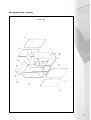
3.2 critical dimensions
H
C
360
A
E
K
L1
P
L2
O
N
R
B
J
D
35 : 50
G
M
F
I
S
Fig 3.2a
Dimensions in millimetres
Table 2
Midimat HT-220
Midmat HT-330
Depth
A
1755
1755
Height
B
1430
1700
Width
C
628
628
Height to gas connection
D
1235
1515
Dimension
K
500
500
Gas Inlet Connection
O
1” BSP M
11/2” BSP M
E
1” BSP M
11/2” BSP M
Safety Valve Connection
Height to Flue Gas Connection
F
555
496
Flue Gas Connection Diameter
M
Ø DN150 *
Ø DN200 *
Height to Air Supply Connection
G
930
1310
Air Connection Diameter
(used when room sealing the Boiler)
N
Ø DN100 **
Ø DN100 **
Dimension
250
H
150
Height to Condense Waste Outlet
I
170
175
Height to Flow/Return Connections
J
1270
1735
P
1” BSP M
1” BSP M
Flow Connection
L1
DN 40 PN6
DN 50 PN6
Return Connection
DN 50 PN6
Spare Tapping
L2
DN 40 PN6
Dimemsion to Air Supply Connection
R
575
575
Condense Waste Connection
S
DN 40
DN 40
* Female socket with M + 10mm ID
** Male spigot with N + 10mm OD
3.3 system guidance
The Midmat HT boilers are designed to operate on a flow to return temperature drop of 20K. Systems
must be sealed and pressurised to operate within the range 0.5 bar to 5.3 bar.
3.4 flue options
The Midmat HT boiler may be used with either an open or room sealed flue/air system. Approximately
200Pa is available as residual flue pressure at the exit from the appliance. Full details regarding flue
specification are given in section 4.3.
6
3.5 thermal performance – heat output limits
The Strata 3 – 220 can be limited to a maximum thermal loading between 42kW and 210kW.
The Strata 3 – 330 can be limited to a maximum thermal loading between 63kW and 316kW.
4.0 appliance
installation requirements
4.1 statutory requirements
Gas Safety (Installation and Use) Regulations (Current Issue).
It is the law that all gas appliances are installed by a registered person, in accordance with the above
regulations. Failure to install appliances correctly could lead to prosecution. It is in your own interest, and
that of safety, to ensure that the law is complied with.
In addition to the above regulations, this appliance must be installed in accordance with the current IEE
Wiring Regulations for electrical installation, (BS 7671), Local Building Regulations, the Building Standards
(Scotland) (Consolidation) Regulations, Bye laws of the Local Water Undertaking and Health and Safety
Document No.635 ‘The Electricity at Work Regulation 1989’.
It should also be in accordance with the relevant recommendations in the current editions of the
following British Standards and Codes of Practice, plus any others that are relevant to the proposed
installation: BS6644, BS6880, IGE/UP/2, IGE/UP/7, & IGE/UP/10.
Important Note: Manufacturer’s instructions must NOT be taken in any way as overriding
statutory obligations.
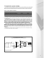
4.2 boiler position
The following considerations must be observed when siting the Midmat HT boiler:
The boiler is not suitable for external installation. The position selected for installation should be within
the building, unless otherwise protected by a suitable enclosure, and MUST allow for adequate space for
installation, servicing, operation, and for adequate air circulation around it. (Refer to fig 4.2a).
This position MUST allow for a suitable flue system and terminal position (Refer to section 4.3). A
connection to a suitable termination point for the discharge of condensate must be available. If this is not
present, a condensation pump with an elevation level of 5 metres (available from MHS) may be fitted to
the appliance. TheMidmat HT – 220 and 330 must be installed on a flat horizontal floor capable of supporting
the boiler and any ancillaries (circa 320kg for the 220 and 360kg for the 330).
In boiler plant rooms where there is a risk of air contamination as a result of halogenated hydrocarbons
(eg contained in spray cans, solvents and cleaning agents, dyes, adhesives) or heavy dust deposits, the boiler
must be provided with a room sealed air supply. (See figure 4.2a) for plant room clearances. If the Strata
3 is operated on a room air dependent basis in these (or similar) conditions, faults may arise. In this case,
no guarantee claim will be accepted. The boiler room must be dry and frost free.
boiler plant room
A
A
Dimensions & Clearances mm
D
A
B
Fig 4.2a
C
E
A
Strata 3 220 & 330
A
500
B
1000
C
650
D
628
E
1755
Above Boiler Model 220
370
Above Boiler Model 330
600
7
4.3 flue
systems
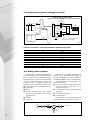
4.3 flue systems
Midmat HT boilers are fully condensing, fully modulating appliances and it is recommended that each boiler
is flued independently, however, it is possible to connect multiple boiler flues together providing no part of
the common flue pipe is horizontal. A suitable flue must be connected to the boiler and routed to
discharge above the roof of the building.
Where it is required that the boiler should be room sealed, an air supply duct must be connected to
the appliance to take air directly from outside the building via suitable fittings.
Under all circumstances, plant rooms must be ventilated in accordance with BS 6644:1991, ventilated
for combustion air and cooling or cooling only dependent on flue type.
The combustion system includes a high pressure fan which is able to overcome a flue or a flue duct plus
air duct total resistance of 200Pa.
Extended horizontal flue duct routes are possible but there must be at least a 3° fall on the flue duct
back towards the boiler, to facilitate condensate removal. (3° = 5.0cm of fall per metre of duct).
Flue ducts must be gas and watertight and resistant to flue gas condensate and suitable for a working
temperature of not less than 120°C. Flue termination position must meet the requirements of BS
6644:1991 and the Clean Air Act Memorandum on Chimney Heights.
Note: The Clean Air Act Memorandum prevents the use of balanced flue appliances discharging at low
level where the total heat input to the plant room exceeds 150kW Gross.
4.4 ventilation requirements
Where the appliance is room sealed, use guidance given in BS 5440:2/2000 for ventilation provision.
Where the appliance takes air for combustion from the boiler house, an adequate supply of fresh air for
combustion and ventilation of the boiler house must be supplied in accordance with BS 6644:1991,
or IGE/UP/10.
The air supply should be achieved using either:
a. Natural ventilation with low level and high level openings.
b. Using a fan to supply air to a low level opening with natural discharge through a high level opening.
c. Using a fan to supply air to a low level opening and a fan to extract air at a high level opening.
Where natural ventilation is used, suitable permanent openings connected directly to the outside air
must be provided. The openings should be fitted with grilles that cannot be easily blocked or flooded or
permit the entry of any foreign bodies.
The free area of the grilles should be as follows:Low Level (inlet) 540cm2 plus 4.5cm2 per kW in excess of 60kW Gross of total rated input.
High Level (outlet) 270cm2 plus 2.25cm2 per kW in excess of 60kW Gross of total rated input.
Note: Total rated input is the sum of the heat input of all gas appliances in the boiler room.
This guidance is taken from BS 6644:1991, alternative guidance is given in IGE/UP/10.
8
4.5 hydraulic system design
The Midmat HT boilers are designed to operate on a flow to return temperature drop of 20K (∆t 20°C).
Systems must be sealed and pressurised and operate within the range 0.5 bar to 5.3 bar. The system design
should incorporate a pressure gauge, visible from the filling point to indicate the system water pressure.
Table 3 - Boiler hydraulic resistance
Model
220
330
Design Flow Rate at 80/60 Flow/Return Temperatures
2.38 l/s
3.57 l/s
Hydraulic Resistance at 80/60 Flow/Return Temperatures
65.0 kPa
62.5 kPa
Design Flow Rate at 50/30 Flow/Return Temperatures
2.62 l/s
3.95 l/s
Hydraulic Resistance at 50/30 Flow/Return Temperatures
82.5 kPa
74.0 kPa
The Signal to start the boiler pump is provided by the boiler, and where the pump motor rating does
not exceed 600 Watt 230V single phase, the pump may be driven directly from power available from the
boiler inbuilt controls.
All systems must be thoroughly cleansed prior to the connection of the boiler. The
system water should be treated to prevent general system corrosion and the
deposition of scale or sludge in the boiler waterways. If installing the boiler onto an old
system, it is recommended to install a spirotech or similar dirt arrester/filter. Failure
to cleanse and water treat the system will render the appliance guarantee void.
If plastic pipes are used for the flow and return pipes, for radiators or under floor
heating, a plate exchanger should be considered between the system water and the
boiler water. If such a separator is not used, the MHS guarantee on all boiler parts will
become null and void, unless it can be proved that the plastic pipes used have a vapour
tight layer.
The connection of the flow and return are located at the top rear of the unit. With regard to servicing,
it is a requirement that isolation valves are installed.
recommended system design
typical single Midmat HT boiler installation
AAV
Flow Header
IV
AAV
IV
IV
SV
IV
IV
Vertical Low
Velocity Mixing
Header
Vmax 0.5m/s
BLR Pump
IV
IV
DOC
LSV
HWS
Load
IV
IV
DOC
IV
Fill Point*
DOC
Heating Load
IV
AAV
Strainer
IV
Strata 3 Boiler
Pumps
DOC
Return Header
Expansion Vessel
* Fill Point. In accordance with BS6644, automatic
pressurisation unit must be installed
Fig 4.5a
9
4.5 hydraulic system design (contd)
recommended system design
typical multiple Midimat HT boiler installation
SV
AAV
Flow Header
IV
AAV
IV
IV
Vertical Low
Velocity Mixing
Header
Vmax 0.5m/s
IV
IV
AAV
Return Header
IV
Strainer
BLR Pump NRV
Strata 3 Boiler
SV
IV
IV
Pumps
IV
IV
IV
Heating Load
IV
HWS
Load
DOC
DOC
Fill Point*
DOC
DOC
* Fill Point. In accordance with BS6644, automatic
pressurisation unit must be installed
Expansion Vessel
IV
LSV
IV
IV
BLR Pump NRV
Strata 3 Boiler
Fig 4.5b
Table 4 - Low velocity vertical mixing header diameter sizing guide
Boiler Power kW
Diameter based upon ∆t 20°C
220
100mm
330
125mm
440
125mm
660
150mm
880
175mm
990
175mm
1100
200mm
1320
200mm
1650
225mm
Tube diameters refer to medium grade or large steel tubes and are calculated using data from CIBSE guide C4
4.6 filling the system
The initial filling of a sealed heating system, and
subsequent refilling, must be by a method that has
been approved by the Water Regulation Advisory
Scheme (WRAS) for that type of heating system.
ie. Non Domestic (Other than in-House) Fluid
Category 4 (C-4). For Category 4 systems, the
approved method of filling must comprise of the
following components in the arrangement shown;
● Control valve
● Strainer
● Verifiable backflow device with reduced
pressure zone (RPZ Valve). Incorporating a
'Type BA' air gap.
● Tundish
● Control valve
MCWS
Strainer
Further more, in accordance with BS6644, for
boiler/s with an input greater than 60kW, an
automatic pressurisation unit must be installed to
automatically replenish any lost or evpourated water.
The pressurisation unit must comprise of the
following components;
● A cistern fitted with a float operated valve
incorporating either a 'Type AG' (C-3), or
'Type AF' (C-4) air gap.
● A presssure booster pump fitted with a single
check valve
● A pressure reducing valve
● A pressure switch
For information on a comprehensive range of
pressurisation units please contact MHS Sales.
RPZ
Heating System
CV
CV
Tundish
10
4.7 gas supply
The Midmat HT boiler is designed and delivered ready for Natural Gas group G20. For operation with
LPG. The LPG conversion kit must be ordered and installed and the multifunctional gas valve adjusted as
necessary. (See section 5.4). The Gas Supplier should be consulted at the installation planning stage in
order to establish the availability of an adequate supply of gas. An existing service pipe MUST NOT be used
without prior consultation with the gas supplier. An existing meter and/or pipework should be of sufficient
size to carry the maximum boiler input plus the demand of any other installed appliance. (BS 6891:1988).
The governor at the meter must give a constant outlet pressure of 20 mbar (8 in. wg) when the
appliance is running on natural gas (G20) or 37 mbar at the regulator when using LPG (G31). The gas supply
should be purged in accordance with IGE/UP/1. WARNING: Before purging open all doors and windows,
also extinguish any cigarettes, pipes and any other naked lights.
4.8 electrical supply
A 240 Volt single phase supply must be present at the proposed boiler location. Wiring external to the
appliance must be in accordance with BS 7671 (the current IEE Wiring Regulations) for electrical installation
and any local regulations which apply.
Wire used for the outdoor sensor, the room unit and the domestic hot water temperature sensor must
have the following minimum cross section, depending upon the cable length.
Table 5
Length m
Minimum Cross Section mm2
Up to 25
0.25
25 ... 50
0.5
70 ... 140
1
The mains cable must be PVC insulated to BS 6500 table 16.
WARNING: THIS APPLIANCE MUST BE EARTHED. (Failure to provide a satisfactory Earth connection
would be a safety hazard and may also result in appliance malfunction).
The method of connection to the mains supply must facilitate complete electrical isolation of the
appliance. A fused double pole switch having a 3mm contact separation in both poles and serving only the
boiler (and its external controls) may be used.
5.0 installation
instructions
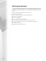
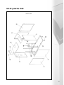
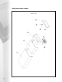
5.1 unpacking the boiler
The boiler is delivered in a fully paletted crate containing the boiler and associated fittings, plus any
other optional ancillary control components in separate cartons.
The boiler crate contains:
● Midimat HT 220/330 boiler.
● Assembly, commissioning and maintenance manual.
● External temperature sensor with screws and plugs.
Built into each unit are the following:
● Siphon for condensation discharge integrated
in exhaust gas collector.
● Flow temperature sensor.
● Thermometer with LCD display.
● Manometer with LCD display.
● SPIRANOX condensing heat exchanger in
austentic (316L) stainless steel.
● ECONOX premix radiant burner,
RPM-controlled.
● Gas control valve, gas/air pressure ratio 1:1.
● Boiler water temperature control.
● Fully automatic ignition.
● Ionisation monitoring.
● Weather-dependent (compensated) control.
11
5.1 unpacking the boiler (contd)
The unit must be inspected immediately after delivery. Any damage to the consignment must be
reported within 3 days.
Firstly move the packaged appliance to the desired location. To unpack the boiler, carefully remove
the outer crate and cut away the outer packaging. By holding the steel base only, lift the boiler and remove
the palette.
5.2 positioning the boiler
The appliance should be moved to the desired location prior to unpacking, making sure that all
clearance dimensions as stated in section 4.2 are adhered to.
Level the appliance in a horizontal position by turning the adjustable feet underneath the base of the
unit. Check that the appliance is in a true horizontal position by using a spirit level.
Once the appliance is in a true horizontal position, the adjustable feet must be secured by the
locking nuts.
5.3 gas connection
The gas connection is located on the upper left hand side of the appliance (viewed from the front) (see
section 3.2). The gas supply should be sized, installed, tested and purged in accordance with IGE/UP/1&2.
The connection to the appliance must include a suitable method of disconnection and a gas control
cock must be installed adjacent to the appliance for isolation purposes.
The gas pipe used to supply the appliance must not allow a pressure drop of greater than 1 mbar from
the meter to the appliance. The nominal inlet working gas pressure measured at the appliance should be
20.0 mbar for natural gas (G20) or 37 mbar (G31) for propane (LPG). The installer should install a pressure
test point adjacent to the gas inlet connection.
The gas supply line should be purged in accordance with IGE/UP/1. WARNING: Before purging open
all doors and windows, also extinguish any cigarettes, pipes and any other naked lights.
5.4 LPG conversion instructions
The Midimat is supplied suitable for use with natural gas. For conversion to LPG, the natural gas injector
must be replaced with the LPG injector (accessed from inside the air inlet duct). The LPG injector is
included in the LPG conversion kit, part No. 96.00044-0404.
Injector Size
220
330
Natural Gas (G20)
10.8mmØ
13.0mmØ
L.P.G (G31)
7.5mmØ
9.7mmØ
The low pressure gas cut off switch will need to be adjusted from approx. 15mbar (G20) to
approx. 27 mbar (G31).
5.5 water connections
Midimat boilers must only be installed on sealed and pressurised systems. All systems must be
thoroughly cleansed prior to the connection of the boiler. The system water must be treated to prevent
general system corrosion and the deposition of scale or sludge in the boiler waterways. If installing the
boiler onto an old system, it is recommended to install a diamante, spirotech or similar dirt arrester/filter.
See section 4.5 for water treatment product stockists. The central heating flow and return connections
are flanged fittings – DN40 PN6 for the M 220 and DN50 PN6 for the Midimat 330. The flow and
return connections are located at the upper rear of the appliance.
A suitable safety valve must be installed onto the boiler flow pipe between the boiler and any
isolation valve. The boiler flow and return pipes must include a method of disconnection and must include
isolation valves.
12
5.6 condensate waste connections
The condensate waste connection is located at the lower rear of the appliance. During the operation
of the boiler
, because of the low exhaust gas temperatures in both the heating boiler itselfand in
the exhaust gas system, a slightl y acidic condensation water ( pH value between 3.5 and 5) is deposited.
The condensate waste connection is a 40mm plastic tube located at the rear of the appliance. Only
plastic components must be used for the condensation discharge. Metal pipes are not acceptable due to
the acidic nature of the condensate.
The built in siphon allows the unit to be connected directly to a drain system. A level control device is
built into the siphon. In the event of a blockage in the condensate line, the burner is automatically switched
off before any damage is done to the appliance.
The siphon drain point is located behind the rear casing panel, next to the condensate water
connection. This must be opened annually in order to flush the condense system and to remove any debris.
If any part of the condensate waste pipe is to be run external to the building or is at risk of freezing,
then the pipe must be suitably insulated to protect it from freezing.
If a suitable drain for accepting the condensate waste is not available nearby to, and below the boiler
(e.g. if the boiler is installed in a basement below ground level), an (optional extra) condensate receptacle
and pump (available from MHS) can be installed adjacent to the appliance. This will collect and remove
condensate to a remote drain up to 5 metres height above the receptacle position. Note that blockage of
the waste discharge will cause the unit to switch off by means of a built in level control device.
It is recommended that the condensate waste pipework should include a method of disconnection and
cleaning points.
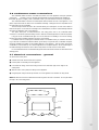
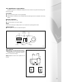
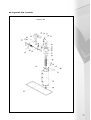
5.7 electrical connections – general
To remove the control panel:● Unfasten the screw which secures the front panel.
● Pull the panel out and away from the appliance.
● From inside the casing, remove the 2 fixing screws on the underside, upper return edge of the
2 side panels.
● Slide the entire control panel/box away from the appliance.
● Hang the panel, using the turned up brackets, on to the appliance cross member for easy access.
Note: All electrical connection cables must be fed through from the rear of the boiler. Do not pass cables
through or fix to the casing panels.
One Screw
One Screw
Casing
Cross
Member
Fig 5.7a
13
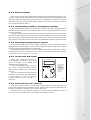
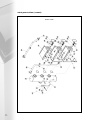
5.7 electrical connections – general (contd)
location of electrical points
5
6
4
3
2
1
6
4
3
2
1
Control Panel Rear Side
weiland plug / socket functions
1
2
L1
PE
3
N
N
Permanent Supply
(L1 + PE + N)
PE
L2
L1
External Gas Safety
Shut Off Valve - LPG
Only (if reqd)
(N + PE + L1)
N
PE
L1
Room
Thermostat/Volt
Free Switch
(L2 + L1)
PR01 / MR03
(N + PE + L1)
4
6
5
Terminal
Block
A1 A2
R1
R2
R3
N
Outside Air Sensor (A1 + A2)
RE2132 Room Unit (R1 + R2 + R3)
KKM2 Cascade Manager (R2 + R3)
0-10V via an adapter '+' R2 '-' R1
0-3V '+' R2 '-' R1
HWS Sensor
or Thermostat
PE L1
HWS Diverter Valve or
HWS Primary Pump
(N + PE + L1)
Fig 5.7b
5.7.1 connecting power supply
The mains electrical connection on the Midimat is made via plus No (1) (see fig 5.7b) with a conductor
cross section of 3 x 1.5mm2.
Wire used for the outdoor sensor, the room unit and the domestic hot water temperature sensor must
have the minimum cross section, depending upon the cable length stated in table 5, section 4.7.
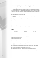
5.7.2 fuses
The Midimat
boilers have 3 electrical f
uses in the boiler control panel. (fig 5.7b).
location of fuses
1
3
x2
2
Phase and Neutral Protection (230 V AC) 5A Fuse
24 V AC 5A Fuse
Fig 5.7c
14
5.7.2 fuses (contd)
Fuses 1 and 2 protect the power supply phase and neutral. Fuse 3 protects the entire 24V AC circuit.
The 24V AC power supply is rectified in the boiler control panel and controls the fan and supplies the room
unit(s) with voltage. The supply voltage of the sensors is not accessibly fused in the boiler control panel.
This applies also for the protection of the ignition transformer. In the case of a fault in these areas, the
boiler control panel must be replaced.
5.7.3 connecting a boiler (transport) pump
It is recommended that the boiler pump be electrically connected to the boiler. The pump will start as
dictated by the boiler, will overrun when necessary and will run when commanded by the boiler's own frost
protection programme.
The signal to start the pump is provided via plug x 33 and where the pump motor does not exceed 600
watts, 230V 1 phase, the pump may be driven directly from power available from the boiler inbuilt controls,
plug x 33 is located on a flying lead and may be found in the top area of the boiler approximately half way
along the length of the boiler. Where the pump motor exceeds 600watts an auxillary relay must be used.
5.7.4 external temperature sensor
Where weather variable/direct on boiler weather compensation control is required, the external
temperature sensor must be installed. The external sensor should be mounted on the North or Northeast
side of the buildings, at approximately 2/3 of façade height.
The external temperature sensor should not be mounted above windows or below eaves. Under no
circumstances may the sensor be exposed to direct sunlight. The external temperature sensor should be
connected via two cores on plug No 4 – see fig 5.7b.
5.7.5 room unit RE 2132
Where room temperature influence, or
remote adjustment is required, a room unit will
need to be installed. This is available as an
additional accessory (see fig 5.7d).
If the room temperature sensor of the room
unit is used, no thermostat/radiator/convector
valves should be installed in the room with the
room unit.
The room unit must not be directly influenced
by insulation or heat sources, such as heat emitters
or direct sunlight. The room unit should be
connected via three cores on plug No 4 –
see fig 5.7b.
Remote tamper
proof temperature
sensors are
available to allow
the controller to
be installed in a
non heated area
Sensor ID
= QAW44
Fig 5.7d
5.7.6 external on/off control
Where this is required a 230V AC volt-free contact must be installed. With the contact open, the
boiler control is switched to the frost protection function, whilst with the contact closed, depending on the
DIP switch configuration of the boiler control, the boiler will operate.
The external on/off control should be connected via two cores on plug (3), terminals L1 and L2, fig
5.7b. Only one of the aforementioned control systems can be utilised at one time.
15
Other types of cascade controllers with a continuous 0 to 3V, or 0 to 10V signal can also be connected.
An optional adapter is required, for 0 to 10V. See Fig 5.7e (Below)
0 - 10v adaptor
To Boiler Socket Nr: 4
Welland Plug
Nr: 4
0-10 volt Adaptor
A1
A2
R1 R2
0v
R3
V+
0-3 volt control direct to boiler plug
Nr: 4 without adaptor.
0-10 volt control via 0-10 volt adaptor
(optional extra)
Welland Connection Plug Nr: 4
Fig 5.7e
5.7.7 cascade controller KKM2
The KKM2 Cascade Manager is available as an accessory (see fig 5.7f ). The cascade controller can
operate up to 5 units. On a load dependant basis, it controls the modulation of the burners, and the
switching of the appliance(s). It includes all necessary sensors and an external temperature control which
adjusts the flow temperature of the cascade system as a function of the outside air temperature and/or
the sensed room temperature via the RE 2132 (if required) or 0-3 or 0-10v input. The KKM2 may also be
set to give a constant flow temperature and can also control a domestic hot water circuit.
Fig 5.7f
16
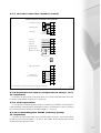
5.7.7 cascade controller KKM2 (contd)
KKM2 sequence controller wiring details
2
4
6
8
9
10
13
14
15
16
17
18
S6
20
19
D5D2D1
21
22
RE 2132 Room Unit
or
External On/Off Controls
12
S5
11
S4
Outside Air Sensor
7
S1
HWS Sensor
5
E
Return Sensor
3
L N
Flow Sensor
1
LN E
Heating Pump 230V ac
230Vac Supply
LN E
HWS Primary Pump 230V ac
RS232
23
24
25
26
27
28
29
30
31
32
33
34
35
36
37
38
Boiler Control Connections
R2
B1
R3
R2
B2
R3
For midimat control
Connect to Plug 4 R2 & R3
B3
R2
R3
R2
B4
R3
B5
R2
R3
Further information can be found in the operating manual of the KKM cascade manager.
Fig 5.7g
5.7.8 domestic hot water temperature sensor (TF)
(if required)
For domestic hot water priority, a KTY 81-210 sensor or a volt free contact thermostat can be used.
Connections are provided at connector No 5 – see fig 5.7b.
5.7.9 LPG operation
For use with LPG, an external gas solenoid valve (if required) may be installed in the gas supply line
outside the building. This interrupts the gas distribution if there is no heat demand or a fault. Connections
for an external solenoid (if required) are provided at plug No 2 – see fig 5.7b.
5.7.10 connecting the DHW primary pump
(if required)
A domestic hot water primary pump can be connected directly to the boiler. The connection should
be made via a 3 core cable to plug No 6 – see fig 5.7b. Max load 2A. Where the pump motor exceeds
2Amps a proprietry relay must be used.
17
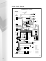
5.7.11 circuit diagram
N
S
L
S
L1
N
N
L
PE
N
L2
3
X43
N
PE
A2
6
N
A1
RE1
PE
N
N PE
PE
L
HWS D/Valve
HWS Pump
L
L
N
PE
L1
L2
FUSE 2 (X)
230 VAC
Supply
230 VAC
2
S
B
L1
PE
X8
N
PE
X42
N
6
1
PE
N
5
3
LPG
Solenoid
L
L
PE
4
2
S
L
F
B
L
N
X41
L
PE
N
N
PE
LIN
L
Fuse (2x)
230 VAC
PE
1
R/Stat
PRO 1
PRO 3
X32
IO
EL
HSP TOP
B
PE
Ignition/Ionisation
J5
PE
N
L
F
N
PE
J6
circuit diagram Strata 3 220/330
S
N
PE
L
N
PRO 2
RE2
2
4
3
Boiler
Pump
X33
A2
LP
N
LL
A1
1
230V DC
230V DC
Fan
LP
3
LL
6
5
2
1
X7
4
B
230V DC
6
1
3
2
N
PE
PE
N
L
N
Gas Valve 230 VAC
L
X26
4
1
L
S
5
2
B
L
PE
N
6
3
X6
L
N
PE
N
L
N
PE
L
PRO 1
K20
4 1
5 2
6 3
K19
K12
S
Q-P
B
S
1
B
3
X20
X22
Transformer
S
Model
330 Only
Q-P
B
X18
B
X18
Limit thermostats
Condensers 12 VDC
Q-P
K18
K9
9
X61
K17
S
2
1
X9
1
VOLT FREE ALARM CONTACT
F
4
X5
6
FURIMAT 762
FUSE 24V
K20
X62
1 4
3 6
K17
K18
K12
K2
A1 A2 R1 R2 R3
X44
X16
K7
5
K0
10
2 5
K18
X63
Q-P
Q-P
S
B
Q-P
1
Gas Pressure Switch
K9
PRO1
6
MRO3
K13
8
16
K9
X3
Limit thermostat water
12 VDC Primary Boiler
2
Fluegas Limit Thermostat 12 VDC
4
X17
1
X19
K9
3
X4
X21
K9
K6
K8
S
4
B
K4
Outside Sensor
Room unit
Cascade Manager
0-10V (via special adaptor)
K0
X45
S
S
B
K2
Water
Pressure Sensor
Return Temperature Sensor
Flow Temperature Sensor
5
D1
K3
S4
K8
S1
1 2 3 4
1
11
HWS
Sensor/
Volt Free stat
K0
RTE
X2
X15
= Weiland Plugs
1
RTE
X12
K5
K5
1
2
3
2
S
X1
K6
B
1
K6
RS232
4
2
S
B
10
20
K7
X10
KO = White
K2 = Brown
K3 = Green
K4 = Gray
K5 = Orange
K6 = Blue
K7 = Red
K8 = Black
K9 = Violet
K12 = Yellow/White
K13 = Braun/White
K14 = Green/White
K17 = Blue/White
K18 = Red/White
K19 = Black/White
K20 = Violet/White
VTE
Fig 5.7h
18
5.8 Add on Modules
5.8.1 Pump module PR 01
The PR 01 pump control serves to control an additional heating circuit pump (pump 2).
Technical Information
● Supply Voltage – 230V 50Hz
(mains from Strata 3 appliance)
● Maximum contact load – 2A
● Maximum contact rating – 120W
140
PR01
Control
Module
60
115
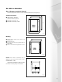
Fig 5.7j
Mounting
● Remove the 4 screws on the front of the
pump control.
● Remove the cover.
● Mount the unit in the space provided inside the
boiler casing.
● Refer to the instructions supplied with the unit.
PR01
Control
Module
Fig 5.7k
NOTE: The DIP switch of the Strata 3 must be
adjusted so that only one direct heating circuit is
controlled (DIP 1 = OFF).
If the power consumption of pump 2 is more
than 120W, an auxiliary relay is to be installed.
Fig 5.7L
19
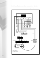
5.8.1 Pump module PR 01 (contd)
X3
PR 01
L
NETZ
N
X2
PUMPE 2
N
L
System
heating
pump
Pump 2
Power Supply
Control Panel Wiring
X3
X16
Weiland
Plug 3
L1 PE N L2
6
5
4
3
2 1
Cable sets are supplied, labeled, and approximately 140cm in length
20
Fig 5.8a
5.8.2 mixer module MR 03
The mixer module MR 03 is used if a standard heating circuit (eg for normal temperatures for radiators)
and a mixed heating circuit (eg for under floor heating 55/45°C) with different flow temperatures are
connected to the Strata 3. The mixer module MR 03 is intended for mounting inside the boiler casing, and
contains a potentiometer for setting the heating compensation slope for the underfloor circuit.
Technical Information
● Supply Voltage – 230V 50Hz (mains from Strata
3 appliance)
● Maximum contact load (pump 2) – 1.0A
● Maximum contact rating (pump 2) – 120W
● Maximum contact load (pump 3) – 1.0A
● Maximum contact rating (pump 3) – 120W
● Supply temperature sensor S7: Type KTY 81210 (PTC)
NOTE:
Ancillary relays required if pump duties are
greater than detailed above.
140
MRO3
Control
Module
60
115
Fig 5.8b
Mounting
● Remove the 4 screws on the front of the pump
control.
● Remove the cover.
● Mount the unit in the space provided inside the
boiler casing.
● Refer to the instructions supplied with the unit.
MRO3
Control
Module
Fig 5.8c
NOTE: The DIP switch of the Strata 3 must be
adjusted so that only one direct heating circuit is
controlled (DIP 1 = ON).
If the power consumption of pump 2 is more
than 120W, an auxiliary relay is to be installed.
Fig 5.8d
21
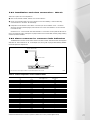
5.8.2 installation and elect connection – MR 03
The MR 03 must be connected in accordance with the schematic diagram – fig 5.8e.
MR 03
X3
X2
X1
SENSOR 7
1 2 R4 R5 R6
NETZ
L
N
PUMP 3
L
N
L1
N
L2
PUMP 2
N
L
X4
M
PUMP 3
PUMP 2
Underfloor
Heating Pump
System
Heating Pump
S7
8
7
6
5
4
3
2
1
Power Supply
RE 2132
Room unit controlling underfloor
circuit (if fitted)
X3
X16
Control Panel Wiring
Weiland
Plug 3
L1 PE
6
N L2
5
4
3
2 1
Pump 2 = Radiator Circuit
Pump 3 = Underfloor Circuit
M = Underfloor mixing valve
S7 = Underfloor circuit mixed flow temperature sensor
Fig 5.8e
22
5.8.2 installation and elect connection – MR 03
There are 3 options for room temperature:● Both circuits, weather variable, without room control influence.
● Room control influence with one room controller for the entire building – must be electrically
connected direct to the boiler. Weiland Plug 4.
● Independent room influence control with 2 room units (one for the radiator circuit – connected
directly to the boiler (Weiland plug 4) and a second room unit for the underfloor circuit connected
to the MR 03 unit).
See section 5.7.5 – Room Unit RE 2132. DIP switch No 1 on the boiler control panel should be set to
ON. If the respective power consumption of pumps 2 and 3 are more than 120W, auxiliary relays (auxiliary
contactors) must be installed.
5.8.3 alarm contacts for common fault indication
TheMidimat has a volt free contact, which closes in the case of a fault. This fault contact can be applied
with 230V AC and a maximum of 1A, via an adapter (X9) see fig 5.8f. X9 plug & lead assembly available
from RVR Spare Parts Department.
X9 Plug & Lead
(Part No. 96.00025-0048)
2
1
2
1
Volt Free Contact
X9
Control Panel
This contact can be used to trigger an audible or an optical alarm signal in the case of a fault.
Fig 5.8f
Table 5 - Sensor temperature versus resistance table
Temperature
°C
-30
-25
-20
-15
-10
-5
0
5
10
15
20
25
30
35
40
45
50
55
60
65
70
75
80
85
90
95
100
Resistance
Ω
1247
1306
1367
1430
1495
1561
1630
1700
1772
1846
1922
2000
2080
2161
2245
2330
2417
2506
2597
2690
2785
2881
2980
3080
3182
3286
3392
Voltage* V
Over S1,S4, S5, S7
—
—
—
—
—
—
1,88
1,93
1,98
2,03
2,08
2,13
2,18
2,22
2,27
2,32
2,36
2,41
2,45
2,50
2,54
2,58
2,62
2,66
2,70
2,74
2,78
Voltage* V
Over S6, AF
1,92
1,98
2,03
2,08
2,14
2,19
2,24
2,30
2,35
2,40
2,45
2,50
2,55
2,60
—
—
—
—
—
—
—
—
—
—
—
—
—
* Measured between both contacts in operation (Sensors are at zero potential against earth)
23
S1
S4
S5
S6
S7
AF
Flow Temperature Sensor
Return Temperature Sensor
Domestic Hot Water Temperature Sensor
Outside Temperature Sensor (KKM2)
MR03 Mixed Flow Sensor
Outside Temperature Sensor (Boiler)
6.0 commissioning
& testing
The Midimat should be commissioned by a competent engineer. Before commissioning the appliance,
the whole gas installation including the meter MUST be purged and tested for gas soundness in accordance
with IGE/UP/1.
Caution: Open all doors and windows, extinguish naked lights and DO NOT SMOKE whilst purging the
gas line.
The entire water system must be thoroughly cleansed and flushed to remove debris, flux residues etc
before opening the boiler isolation valves and filling the boiler. Particular care must be taken where the
appliance is being retro-fitted into an old/existing system, as system silt or magenite can be very damaging
to the new boiler.
Following cleansing and flushing, the system must be dosed with a good quality water treatment to
prevent corrosion and the formation of scale. Failure to observe these requirements will
render the guarantee on the product void. Cleansing, flushing and water treatment
must be carried out in accordance with the requirements of BS 7593:1992.
The return pipework must include some method of filtering or straining. The filter or strainer must be
fitted with isolation valves to allow easy cleaning with the minimum amount of water loss and water
replenishment.
Note: A low water pressure switch is included in the boiler and interlocked to shut the boiler down in the
event of the water pressure falling below 0.5 bar.
Note: TheMidimat boiler has heat exchangers fabricated from 316L stainless steel.
It is most important that the compatibility of any flux is checked with the flux
supplier before use, and that any flux manufacturers recommendations are strictly
followed with regards to use in conjunction with stainless steel.
6.1 filling the boiler
TheMidimat must be filled by a competent person using one of the approved methods in BS 6644:1991.
Fill the installation to the system design cold fill pressure and vent the boiler via the air release valve on the
boiler primary heat exchanger. See section 4.6 'filling the system' for guidance.
24
6.2 appliance operation
The start of operation of theMidimat heating boiler should commence only after the following points
have been checked:
Flue system
● Check that the flue system is correctly assembled.
● Ensure that the connections for the condensate drain are water tight and the condensate can be freely
drained.
Electrical connections
● ON/OFF switch set to OFF.
● Check the polarity of the power supply.
Water
Check that the setting of the safety valve is correct. Max boiler operating pressure 6 bar.
System controls
● Set all system controls to the required set points.
Display
ECO/ECO
Plus Switch
Has no Function
On/Off
Switch
STATUS
ECO
PLUS
RESET
Reset Button
TEST
ECO
Engineers Button
Test Button
Fig 6.3a
6.3 initial
lighting/commissioning
gas valve adjustment
TheMidimat must be regulated with regard to
the CO2 content in the flue gas.
Note: Regulation via the burner pressure is not
possible.
Gas
Valve
N
N
L
V
V
+2
L
1
0
+1
-1
0.75
-2
1.5
2
3
“N” minimum
burner output
adjustment
“V” maximum
burner output
adjustment
Fig 6.3b
25
6.3 initial lighting/commissioning (contd)
Turn on the appliance ON/OFF switch
TheMidimat begins with a two minute de-aeration program. After this 2 minute program the appliance
will start. If the Strata 3 does not start up and the message IGNITION FAILED is flashing on the status
indicator on the display panel, press the red re-set button to allow up to four further automatic ignition
attempts.
If ignition is still not established:
● Ensure the gas supply is correctly purged of air.
● Slightly increase the setting of the minimum burner output adjustment (a) and then press the red
re-set button.
● Approximately one minute after ignition, turn the green potentiometer on the boiler control panel to
setting ‘60’.
● Press the ‘Engineers’ button twice.
The status indicator shows 10 MIN LOW. The Strata 3 will now work for 10 minutes in
commissioning/testmode.
● Turn the green potentiometer to the left to 20°C: this corresponds to maximum output.
● Measure the CO2 value directly for maximum output by analysing flue gas in the flue system.
Refer to table 6 below:
Table 6
Type of Gas
Natural Gas G20
LPG G31
Injector Diameter
(mm)
220 10.8mm
330 13.0mm
220 7.5mm
330 9.7mm
Minimum Output CO2 %
7.8 - 8.4
10.0 - 10.6
Maximum Output CO2 %
8.9 - 9.4
10.9 - 11.4
Note: Function of adjustment screw for maximum output ("V")
Setting a higher figure increases output
Setting a lower figure reduces output
● Turn the green potentiometer to 60°C (minimum output) and then check/adjust combustion to
obtain value as shown in table 11.
Note: Function of adjustment screw for minimum output ("N")
Turning adjustment towards '+' figures increases output.
Turning adjustment towards '-' figures reduces output.
● Now turn the green potentiometer again to the left to 20°C (maximum output). Check again the
CO2 value for maximum output.
● Correct the value, if required, with the maximum output screw ("V").
● Press the ‘Engineers’ button once. The Strata 3 switches back into automatic operation.
Note: After ten minutes in test mode, the Strata 3 automatically returns itself to automatic operation.
26
6.4 potentiometer adjustments
6.4.1 limiting the output for heating operation
The nominal heat output for the boiler can be limited if required to any value between 42kW and
210kW for the Midimat 220 and between 63kW and 316kW for the Strata 3 330. The maximum output
continues to be available for domestic hot water production.
To adjust the limit:
● Press the red ‘reset’ button. On the lower line in the display, the flow temperature T1 of the sensor
S1 is displayed.
● Press the ‘service button’.
● For the limit to be adjusted the red potentiometer must be turned. The display shows the old value
to the left and the new value to the right ( – – means: max output).
● By pressing the ‘service button’ again, the new value is stored.
MRO3
DIP Switches
Service Button
Fig 6.3c
6.4.2 setting weather compensation
● If direct-on-boiler weather compensated flow temperatures are required, then ensure the (supplied)
outside air temperature sensor has been installed and DIP switch No 2 has been set to ‘on’
● The boiler is supplied with the compensation slope shown (fig 6.4a) set as default.
Note: The default slope is obtained when the red and blue potentiometers are set in the vertical position.
● If the default settings are not applicable to the needs of the system user, then the angle of the slope
may be changed by adjustment of either the blue or red potentiometers, or both.
Adjustment of the red potentiometer raises or lowers the flow temperature at low outside (design)
(-1°C) air temperature. Adjustment of the blue potentiometer raises or lowers the flow temperature at
the end point (high) (20°C) outside air temperature. Each potentiometer has the range of +20°C and
-20°C about the default point but with a limiting factor that the maximum flow temperature is 85°C.
See graphs following which show the range of parallel displacement of the compensation slopes.
27
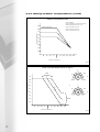
6.4.2 setting weather compensation (contd)
default compensation slope
Dip Switch Settings
When compensation req'd outside sensor must be
installed and dip switch No.2 set to "ON".
90
Max Flow Temperature
Slope A - Dip 6 ON & Dip 7 OFF
80
Slope B - Dip 6 OFF & Dip 7 ON
A
Slope C - Dip 6 OFF & Dip 7 OFF
Boiler Flow Temperature ºC
70
B
60
C
50
40
30
20
10
-20
-15
-10
-5
0
+5 +10 +15 +20 +25
-1
Outside Air Temperature ºC
Fig 6.4a
range of parallel displacement of slope A
*
1
RED
90
*
-20
+20
K
80
-20
RED
+20
70
*
2
60
fau
de
50
40
+10
-10
lt
Boiler Flow Temperature ºC
+10
-10
K
+20
-20
30
20
*
BLUE
+20
BLUE
10
-20
-20
-15
-10
-5
0
+5 +10 +15 +20 +25
-1
Outside Air Temperature ºC
Fig 6.4b
28
6.4.2 setting weather compensation (contd)
range of parallel displacement of slope B
*
1
+10
-10
K
90
RED
-20
*
-20
70
RED
+20
+20
*
2
60
50
40
+10
-10
lt
fau
de
Boiler Flow Temperature ºC
80
K
+20
-20
30
20
*
BLUE
+20
BLUE
10
-20
-20
-15
-10
-5
0
+5 +10 +15 +20 +25
-1
Outside Air Temperature ºC
Fig 6.4c
range of parallel displacement of slope C
*
1
+10
-10
K
90
-20
Boiler Flow Temperature ºC
80
RED
+20
RED
70
*
2
60
*
-20
+20
+10
-10
50
K
40
-20
+20
30
20
*
10
BLUE
+20
BLUE
-20
-20
-15
-10
-5
0
+5 +10 +15 +20 +25
-1
Outside Air Temperature ºC
Fig 6.4d
29
6.4.3 adjusting the fixed point of the mixer circuit
If the MR 03 mixer control is connected to the Strata 3, the fixed point of the heating curve of the
mixer can be adjusted.
● Press the red ‘reset’ button. On the lower line in the display, the supply flow temperature T1 of the
sensor S1 is displayed.
● Press the ‘service button’
● Press the red ‘reset’ button 3 times. On the display (MI MIN) is displayed.
● Now turn the red potentiometer on the boiler control panel, in order to adjust to the required fixed
point.
● The display will be showing the old value to the left and the new value to the right.
● By pressing the ‘service button’ again the new value will be stored.
6.4.4 adjusting the domestic hot water temp.
If there is a hot water temperature sensor connected, the hot water set point temperature can be
adjusted by the green potentiometer.
Adjustable range: 20°C…60°C
The hot water temperature can be read from the display.
6.4.5 hot water thermostat
With a hot water thermostat connected, the required temperature can be adjusted by the thermostat.
The green potentiometer, for the hot water preparation is then out of operation and therefore the
temperature will not be displayed on the display panel.
6.5 switching off the appliance
● Switch the on/off switch on the appliance control panel
● Turn off the gas supply.
Note: Turning off the appliance will leave the system at risk of freezing during winter months and will put
out of action the automatic pump exercising routine. If the only reason for shutdown is that normal heating
is not required, it is recommended to leave the boiler on and turn off or turn down any external controls.
30
6.6 screen display
The screen display indicates information about the operating condition of the Strata 3 in plain text. The
displays are distinguished as operation messages (non flashing) and fault messages (flashing).
6.6.1 operation messages (non flashing)
In the case of the following status signals, the Midimat is in normal operating mode.
Standby
No heat demand (boiler not required to be on)
Pre-Purge
Combustion chamber is being pre-ventilated with air from the burner fan
Ignition
The ignition sequence of the burner is initiated
Heat-operate
The boiler is operating in central heating mode
Tap-operate
The boiler is operating to produce domestic hot water
Flue-emission
The boiler is operating in test mode at mid output to enable flue gas emissions to be checked (auto
expires after 10 min)
10 min Low
The boiler is operating in engineers test mode for adjustment purposes (auto expires after 10 min)
Post Purge
Combustion chamber is being post ventilated with air following boiler operation
Limit F/R
The flow and/or return temperature is too high (currently)
Fan high
The burner fan is running too fast (currently)
Fan low
The burner fan is running too slow (currently)
Fault room u
There is a fault with the modulating unit (RE 2132) or Cascade manager (KKM2) or a fault in the wiring
to these controls (in the case of the RE 2132 controlling the boiler runs continuously in heating mode
to protect the building)
Fault Outside
There is a fault in the outside air sensor or in the wiring to the sensor or the DIP switches are
incorrectly set to ask the boiler to look for an outside sensor when there is none installed.
Service
The service interval time has expired and the boiler should now be maintained (1 year)
Serv. Button
The service button is being depressed.
De aeration/venting
The boiler pump if fitted is operating to remove any possible collection of air from the heat
exchangers. (Occurs when power turned off/on and after reset of fault).
6.6.2 operating data display
The second line of text displays values such as temperature, percentages etc and the red reset button
may be used to scroll through (for information) the values of the various sensors that are/may be
connected in the boiler plus fan speed.
Table 7 - Sensor Identification
T1:
Flow temperature
T4:
Return temperature
T5:
Domestic hot water temperature*
—-: Thermostat opened, or no sensor/thermostat connected
00: Thermostat closed
T6:
Outside temperature*
T7:
Mixer supply flow temperature* (MR 03)
Room 1:
PWM signal from the room unit for the standard heating circuit*
Room 2:
PWM signal from the room unit for the mixer circuit*
Speed:
Fan speed
* These values in the table are displayed only if the corresponding sensor/corresponding room unit are
connected to the Strata 3.
The normal status indicator is returned by pressing the ‘reset’ button once more after the
display (PUMP 1). If the ‘reset’ button is not pressed for 4 to 5 minutes, the normal status display
returns automatically.
31
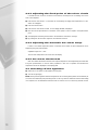
6.6.3 Engineers button
This button is reserved for the Service Engineer.
Note: Pressing this button once instructs the Strata 3 to operate at half load. The status indicator shows
(EMISSIONS). If the 'Engineers' button is not pressed again within 10 minutes, the Strata 3 switches back
into automatic operation.
After further pressing during the (EMISSIONS) display, (10 MIN LOW) appears on the status indicator.
In this position, the loading can be adjusted, with the green potentiometer, between 42kW and 210kW
(Strata 3 220) or 63kW and 316kW (Strata 3 330).
By pressing the 'Engineers' button during the display of (10 MIN LOW), the Strata 3 switches back into
automatic operation. After 10 minutes of ’10 min low’ operation, the Strata 3 also automatically returns
itself into automatic operation.
6.6.4 STB test button
This ‘test’ button is provided in order to be able to simulate the function of overheating of the heating
water. By pressing the ‘test’ button, the display (LIMIT) appears. During this display, the function of the
Strata 3 is shut down. The boiler commences operation when the button is released. If the ‘test’ button
is pressed for longer than 3 minutes, the ‘flashing’ (STB-WATER 1) alarm appears. The function of the
Strata 3 is then locked out.
The Strata 3 can also be locked out more quickly. For this purpose press the 'test' and the 'Engineers'
button simultaneously. To restart the boiler following a lockout condition, press the ‘reset’ button, the
Strata 3 returns to automatic operation.
7.0 boiler operation adjustment
(setting of dip switches)
7.1 adapting the control to the heating system
Service Button
DIP Switches
1
2
3
4
5
6
7
8
ON
OFF
Fig 7.1a
To access the DIP switches, the control panel may need to be removed: (early versions)
● Remove the four screws on the control face.
● Carefully remove the control panel away from the face.
● Do not allow the panel assembly to drop – the panel can be temporarily ‘hung’ over the casing cross
member. See fig 7.1b.
32
7.1 adapting the control to the heating system (contd)
One Screw
One Screw
Casing
Cross
Member
Fig 7.1b
The following specifications must be adjusted:
● Whether the boiler is to be controlled with direct weather compensation.
● Whether an underfloor mixer circuit is connected.
● Whether a room unit, cascade control or a volt free switch are connected.
● Whether the primary heating circuit is a high, medium or low temperature operation.
● Whether a primary pump or a three-way diverter valve are employed for the hot water
production control.
Heating Circuit Design
Heating Circuits
Maximum Flow Temperature °C
High Temperature
85
Medium Temperature
70
Low Temperature
55
33
7.2 DIP switch settings
Dip Switch 1
OFF
ON
No Mixing Valve Control Fitted
Underfloor Zone Mixing Valve Control Fitted (MR03)
Dip Switches 6 & 7 (system operating temperature)
Dip Switch 6
6 OFF 7 OFF Low Temp 55ºC
6 OFF 7 ON Med Temp 70ºC
6 ON 7 OFF High Temp 85ºC
6 ON 7 ON High Temp 85ºC
OFF
ON
Radiator Circuit (mt 70/50ºC)
Radiator Circuit (ht 85/65ºC)
Dip Switch 7
OFF
ON
1 x Room Unit (RE2132)
2 x Room Units (RE2132)
Dip Switches 3 & 4
3
4
Off Off Remote / Remote
On Off Sensor / Remote *
On On Sensor / Sensor
Dip Switch 2
OFF
ON
No Outside Air Sensor Fitted
Outside Air Sensor Fitted
Dip Switch 3
OFF
ON
Modulating Room Unit Installed
No external controls fitted.
On/Off controls fitted.
Cascade controls for multiple boilers.
Dip Switch 5
Dip Switch 5
OFF
ON
OFF
Analogue Unit 0-3V
PWM Unit (RE2132)
Cascade not fitted
Cascade controls fitted
Dip Switch 4
Dip Switch 4
Dip Switch 4
OFF
ON
OFF
* Room unit as Remote Control ONLY
* Room unit with Sensor
No External
controls
ON
ON
OFF
On/off
Analogue
Room Stat
cascade
Time Clock 0.15 - 2.85V **
Voltfree Switch
0-3 or
(0-10 via adaptor)
ON
PWM
cascade
(KKM2)
Dip Switch 8
(Method of charging DHW cylinder)
OFF
ON
Pump
Divertor valve
* Remote = Room unit with temperature
sensor turned off and unit acting
just as a remote controller
Sensor= Room unit with temperature sensor active
34
** 0-10 volt control panel via adaptor
8.0 maintenance
and inspection
8.1 maintenance procedure
After 365 operating days (8760 hours) the message ‘service’ appears in the display. The following work
must then be carried out:
1. Refer to the user with regard to any known problems, or any other comments about the appliance.
2. We recommend that the fault data from the boiler control panel be read via a lap top computer and
RS-232 interface. The service software is available from MHS Boilers Ltd. The cause of frequent faults
must be identified and corrected.
3. Check the flow and return water connections for soundness.
4. Check the system pressure. Minimum 0.5bar.
5. Remove the casing panels and check the general condition of the boiler visually. Any evidence of
leakage must be corrected.
6. Remove the burner. Check the primary heat exchanger for contamination. If required, the primary
heat exchanger can be cleaned with a vacuum cleaner or a nylon brush, do not use a PVC or a steel
brush. It is not normal to clean or gain access to the flueways of the secondary heat exchangers, for
further information, please contact the Technical Department.
Note: The burner must never be touched with the hand and must never be cleaned mechanically, this can
cause damage to the surface.
7. Check the bolts for fixing the burner lance to the burner plate. The bolts must be tightened if required.
8. Check the gap between the ignition electrode and the burner (4 to 5mm). If required, bend the ignition
electrode cautiously. Do not touch the surface of the burner.
9. Empty and flush out the condensate siphon located behind the rear panel of the boiler.
10. Check the combustion fan for contamination. If required this must be cleaned.
11. Measure the CO and the CO2 content in the exhaust gas. If necessary regulate the combustion (see
section 6).
12. Check the gas carrying components for soundness.
After this maintenance has been carried out, press and hold the ‘service’ button for 10 seconds. The
service signal is then deleted from the display. If the maintenance is carried out before expiration of the
service interval and if no service signal has yet appeared in the display, the service button must be pressed
for 10 seconds. The indication (SERVICE) appears in the display and the already counted days are set to
zero (‘0’). For this procedure the boiler must not be in fault condition with a flashing display.
35
9.0 fault
diagnosis
9.1 fault list
Possible faults are entered in the following tables. The right column contains the corresponding line
numbers of the error correction list – see section 9.2. The error correction list contains possible causes
as well as information about the elimination of the fault.
Fault Indication on the Display
Type of fault
(no text)
Strata 3 is turned on, ON/OFF switch does not light up,
no indication in the display.
Error correction list line
number – Section 9.2
14, 29, 31
(no text)
ON/OFF switch lights up, however, no indication in the display.
14, 29, 31
FAULT RU
Strata 3 does not receive any PWM signal
from the room unit or KKM2
1, 2, 4, 33, 44
FAULT OS
Interruption of the connection to the outside temperature sensor
1, 3, 33
IGNIT FAULT
No flame after 4 ignition attempts
12, 13, 15, 16, 17, 30, 31
FLAME OUT
Flame goes out 4 times in sequence in operation
13, 15, 17, 23, 27
STB WATER
STB water limit exceeded*
5, 6, 7, 21, 25, 26, 31
STB EXHAUST GAS
STB exhaust gas limit exceeded*
6, 7, 21, 25, 28
FAN HIGH
Controller identifies fan speed too high
9, 11, 29, 31, 33
FAN LOW
Fan speed too low
9, 10, 11, 18, 29, 31, 33, 44
FAN OP
Fan operation is identified when fan should be off
17, 30
FLAME W/O OP
Flame identified when burner should be off
17, 30
SX INTERRUPT
Connection to sensor x interrupted (S1: flow temperature sensor,
S4: Return temperature sensor, S7: Mixer circuit sensor
3, 33
GAS VALVE
Connection to the gas multi purpose valve interrupted
16, 21, 29, 31, 33
EEPROM
Fault during the checking of the EEPROM in the controller
29, 35
FAULT SOFT
Software error in the controller
29, 35
RESET BUTTON
Fault during the checking of the ‘reset’ button
29, 34, 35
LIMIT F/R
Boiler temperature too high
5, 6, 7
SERVICE
Maintenance interval expired
‘45
A3
Connection to the gas multi purpose valve interrupted
16, 21, 29, 31, 33, 35
A6
Fault during the checking of the ‘reset’ button
29, 34, 35
A7
Fault during the checking of the EEPROM in the controller
29, 35
A9
Software error in the controller
29, 35
A0, A1, A2, A4
Fault in the controller
29, 35
The following faults are visual problems and the right column contains possible error corrections as above, to eliminate these faults.
CO content too high
15, 27
CO2 content too high
15, 23
CO2 content too low
15, 27
Yellow flames
‘23
Hot water temperature too low
3, 22, 39
Output too low
’22, 15
*STB = Limit Thermostat
36
9.2 error correction list
The error correction list contains possible causes as well as information about the elimination of
the fault.
Line Number
Cause of the Fault
1
DIP switch not correctly set
Remedy
Adjust according to the instructions
2
Room unit KKM2 not connected correctly
Check wiring
3
Sensor not connected correctly or defective
Measure resistance, replace where appropriate
4
Defective room unit/KKM2
Replace room unit, where appropriate
5
Short circuit in the cable to the flow
temperature sensor S1
Check cable, replace where appropriate
6
Pump does not turn, possibly seized
Check connections:
attempt to turn the shaft with a screwdriver
7
Water loss
Search for leakage and correct, refill system
9
Fan not connected correctly
Check connections
10
Fan is dirty
Clean fan (see section 8.0)
11
Fan is defective
Replace fan
12
Gas shut off valve closed
Open gas shut off valve
13
Gas pressure too low
Check gas supply cross section and gas meter
14
Defective fuse (to the left on the boiler control panel)
Replace fuse
15
Minimum or maximum adjustment at the
gas multi-purpose valve not correct
Regulate again (section 6)
16
Gas multi-purpose valve is not connected correctly
Check connections
17
Ignition cable not connected correctly
Check cables for over heating,
and security or moisture
18
Defective transformer
Replace transformer
19
Siphon is dirty/blocked
Flush siphon, and check condense
waste system is clear
21
Contact resistance at the STB water or
at the STB exhaust gas too high
Measure resistance over STB,
if resistance is over 1Ω, replace STB.*
22
Resistance in the air supply/exhaust gas system too high
Check length and cross section, possibly clean
23
Flue gas re-recirculation
Check exhaust connections
25
Heat exchanger is dirty
Clean
26
STB water is defective
Replace STB *
27
Incorrect or no gas injector, not mounted correctly
Check gas injector
28
Defective STB exhaust gas
Replace STB *
29
Defective control panel
Replace boiler control panel
30
Incorrect position of the ignition electrode
Carefully bend, the gap distance to the burner
must be 4 to 5mm
31
Damp
Wipe up water, possibly dry with an electric hairdryer
32
Mains connection not correct
Check and rectify
33
Wiring interrupted
Check and rectify
34
‘Reset’ button pressed too long, possibly jammed
Press ’reset’ button briefly, check whether it sticks;
if the fault does not disappear,
then replace boiler control panel
35
Earth wire not attached correctly
Press ‘reset’ button, check earth connection.
If the fault does not disappear,
then replace boiler control panel
39
Hot water primary pump does not work correctly
Check pumps, replace where appropriate
44
Fuse 24V defective
Replace fuse
45
Maintenance interval expired
Press service button for 10 seconds and
carry out maintenance/inspection.
*STB = Limit Thermostat
37
10.0 guarantees
The boiler body and exhaust system both carry a five year guarantee against defect in material or
manufacturing process. The burners and all electrical components and other component parts carry a one
year guarantee. This guarantee only applies if correct commissioning and regular maintenance has been
carried out.
In addition, no guarantee is made for damages which have arisen from:
● Unsuitable and inappropriate use
● Erroneous assembly,commissioning or servicing by unqualified persons
● Erroneous or careless treatment
● Incorrect burner adjustment
● Lack of, or unsuitable water treatment additives
● Non-observance of the installation, commissioning and maintenance instructions
● Inappropriate modifications or repair work carried out by the customer or third parties
● Contaminated combustion air
● Waterside contamination (fouling, scaling etc).
38
11.0 parts list
Strata 3 220
39
11.0 parts list (contd)
Strata 3 220
40
11.0 parts list (contd)
Strata 3 220
41
11.0 parts list (contd)
Strata 3 220
42
11.0 parts list (contd)
Strata 3 330
43
11.0 parts list (contd)
Strata 3 330
44
11.0 parts list (contd)
Strata 3 330
45
11.0 parts list (contd)
Strata 3 330
46
QW/1101/4511