1
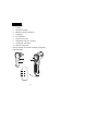
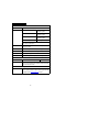
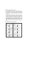
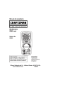
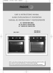
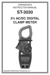
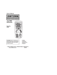
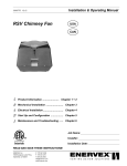
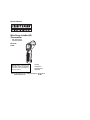
Owner's Manual Wide Range InfraRed (IR) Thermometer with type K input and Laser Pointer Model No. 81998 HOLD HOLD LOG LOG 20 0.95 79.3 HI HI AT 3 91.9 ¡F ¡F LOW LOW Set MODE CAUTION: Read, understand and follow Safety Rules and Operating Instructions in this manual before using this product. Safety Operation Maintenance Español © Sears, Roebuck and Co., Hoffman Estates, IL 60179 U.S.A. www.craftsman.com 031808 TABLE OF CONTENTS Warranty Page 3 Safety Instructions 4 Controls 5 Specifications 6 Battery Installation 7 Operating Instructions 8 Non-Contact (IR) Temperature Measurements 8 Backlight and Laser Pointer 9 Contact (type K) Temperature Measurements 9 Test LOCK feature 9 Temperature units (C/F) 10 The MODE button options 10 Automatic Emissivity 11 Lock feature 12 High and Low Alarm Feature 13 Over Range indication 13 IR Measurement Notes 13 Distance-to-spot Ratio 14 Emissivity and IR Measurement Theory 15 Emissivity Factors for Common Materials 15 Maintenance 16 Battery Replacement 16 Troubleshooting 17 Service and Parts 17 2 ONE YEAR FULL WARRANTY CRAFTSMAN PROFESSIONAL ONE YEAR FULL WARRANTY. If this product fails due to a defect in materials or workmanship within one year from the date of purchase, RETURN IT TO ANY SEARS STORE OR OTHER CRAFTSMAN OUTLET IN THE UNITED STATES for free replacement. This warranty gives you specific legal rights, and you may also have other rights which vary from state to state. Sears, Roebuck and Co., Hoffman Estates, IL 60179 For Customer Assistance Call 9am - 5pm (ET) Monday through Friday 1-888-326-1006 WARNING: USE EXTREME CAUTION IN THE USE OF THIS DEVICE. Improper use of this device can result in injury or death. Follow all safeguards suggested in this manual in addition to the normal safety precautions used in working with electrical circuits. DO NOT service this device if you are not qualified to do so. 3 SAFETY INSTRUCTIONS This meter has been designed for safe use, but must be operated with caution. The rules listed below must be carefully followed for safe operation. 1. Use extreme caution when the laser pointer is on 2. Do not point the beam toward anyone's eye or allow the beam to strike the eye from a reflective surface 3. Do not use the laser near explosive gases or in other potentially explosive areas 4. ALWAYS turn off the power and disconnect the test leads before opening the cover to replace the fuse or battery 5. NEVER operate the meter unless the back cover is in place and fastened securely 4 CONTROLS 1. Laser pointer 2. IR Sensor 3. Measurement Trigger 4. Battery and Switch compartment 5. LCD Display 6. Function Buttons 7. Type-K thermocouple 8. Temperature units ( C or F) switch 9. Test lock ON / OFF switch o o 10. Alarm ON / OFF switch Note that switches are located in the battery compartment behind the battery. 1 2 0.95 HOLD HOLD 5 3 6 79.3 ¡F ¡F 20 LOG LOG AT3 HI HI Set 91.9 LOW LOW MODE 4 8 7 5 SPECIFICATIONS IR Non-Contact Thermometer Range /Resolution -20 to 1400°F (-28 to 760°C) / 0.1° Accuracy -20 to 30°F (-28 to -1°C) ± 2.0%rdg or ±6°F/3°C whichever is greater 31°F to 150°F (-0.5 to 65°C) ± 2.0%rdg or ±4.5°F/2.5°C whichever is greater 151°F to 600°F (66 to 315°C) ± 2.0%rdg or ±4°F/2°C whichever is greater 600F to 1400°F (316 to 760°C) ± (2.5%rdg + 5°F/2.5°C) Note: Accuracy is specified for the following ambient temperature range: 73 to77°F (23 to 25°C) Emissivity 0.10 to 1.00 adjustable; Note: Automatic emissivity adjustment above 212°F (100°C) Distance-to-spot ratio D/S = 13:1 ratio (D = distance; S = spot or target) Laser pointer Class 2 laser < 1mW power; Wavelength is 630 to 670nm Spectral response 8 to 14 m (wavelength) Repeatability ± 0.7% of reading or ± 1.8°F (1°C) whichever is greater Type K Contact Thermometer Range / Resolution -58.0 to 1472oF (-50.0 to 800oC) 0.1o<2000, 1°>2000 Accuracy ± (1.5% of rdg + 2ºF/1ºC) Note: Accuracy is specified for the following ambient temperature range: 64 to 82ºF (18 to 28ºC) Type K Bead Wire Probe (supplied) Range -58.0 to 482oF (-50.0 to 250oC) Note: An optional probe that is rated to the full range of the meter is available from the www.craftsman.com website. 6 General Specifications Display Backlit LCD display with function indicators Response time 1 second approx. Over range indication “---------“ Operating Temperature 32°F to 122°F (0°C to 50°C) Operating Humidity < 80%RH Storage Temperature 14 to 140°F (-10 to 60°C) Storage Humidity < 90% Power Supply 9V battery Automatic Power Off 7 seconds, with LOCK to disable Weight 6.4 oz. / 180g Dimensions 3.2 x 1.6 x 6.3” (82 x 42 x 160mm) 7 BATTERY INSTALLATION When the low battery symbol appears on the display, replace the meter’s battery (9V). The battery compartment is located behind the panel that surrounds the meter’s trigger. Open the compartment by pulling the panel down from the trigger area. Replace the 9V battery and close the battery compartment cover. NOTE: If your meter does not work properly, check the battery to make sure that it is still good and properly inserted. OPERATING INSTRUCTIONS Non-Contact (IR) Temperature Measurements 1. Hold the meter by its handle and point it toward the surface to be measured. 2. Pull and hold the trigger to turn the meter on and begin testing. The temperature reading, the flashing ‘SCAN’ icon, the emissivity, and the unit of measure will appear. Note: Replace the 9V battery if the display does not switch on. 3. Release the Trigger and the reading will hold for approximately 7 seconds (HOLD will appear on the LCD) after which the meter will automatically shut off. The only exception to this is if the LOCK mode is set to ON. Note: Select the temperature units (ºF/ºC) using the switch inside the battery compartment 8 Backlight and Laser Pointer 1. While pulling the Trigger, push the backlight/laser button once to turn on the backlight. 2. Press it again to turn on the laser pointer. When the laser is ON the laser icon will appear in the LCD. 3. Press the laser button to turn the backlight off. 4. Pressing it again turns the laser off. Note: Backlight and Laser settings will be retained after the meter powers down. Type-K (contact) Measurements 1. Plug the Type-K thermocouple sensor into the jacks at the bottom of the instrument. 2. Pull the trigger to turn the instrument ON. 3. In order to keep the instrument’s power on while testing, the user can a:) hold the trigger or b:) lock the instrument ON by setting the center dip switch to the ON position (switches are located inside of the battery compartment). 4. Repeatedly press the MODE button until the bottom display line of the LCD reads ‘T k’. The temperature shown to the right of the ‘T k’ symbol is the temperature that the Type-K thermocouple is sensing. 5. Hold the thermocouple in air or touch the tip of the sensor to the device that is to be tested. The LCD’s bottom temperature display will provide the measurement value. Note: The supplied thermocouple is rated for 482°F (250°C). For higher temperatures you can purchase a high temperature thermocouple from www.craftsman.com. Temperature Units The temperature units can be set to °F or °C using the top switch located in the battery compartment. Test Lock feature The Test LOCK feature locks the meter in scan mode (automatically pressing the trigger indefinitely). This feature is useful for long term temperature monitoring and hands free use. To activate the LOCK feature set the center switch inside the battery compartment to ON. 9 The MODE button options The MODE button is used to access the programming functions of the instrument. The selected function is displayed on the bottom line of the LCD. Each parameter is listed below with a detailed account of its use. Press the MODE button to step from one parameter to the next. EMS (Emissivity Value) To change the emissivity value, use the UP and DOWN arrows (the range is 0.10 to 1.00). The current emissivity setting is always shown at the top of the LCD display. A setting of 0.95 covers about 90% of all applications. Emissivity is discussed in a dedicated section of this manual. MAX (Maximum function) In the MAX mode, only the highest reading encountered in the current measurement session is displayed MIN (Minimum function) In the MIN mode, only the lowest reading is displayed DIF (Max minus Min value) In the DIF mode, the MAX less the MIN is displayed. AVG (Average value) In the AVG mode, all of the readings in the current measurement session are averaged and the value is displayed. HAL (High Alarm setting) The temperature that, when exceeded, causes the audible/visual alarm to trip. LAL (Low Alarm setting) The temperature that, when exceeded high to low, causes the audible/visual alarm to trip. T k (Type-K contact thermocouple sensor function) The temperature reading of the Type-K contact probe is shown next to the ‘T k’ icon display. If the sensor is not correctly inserted to the meter the display will show all dashes ‘-----‘. The supplied thermocouple is rated for 482°F (250°C). For higher measurements you can purchase a high temperature thermocouple from www.craftsman.com that is rated to the full range of this Infared thermometer. 10 Automatic Emissivity Adjustment The 81998 has the ability to automatically calibrate the emissivity setting. However, in order to do so, the temperature of the measured surface must be above 212ºF (100ºC). Follow the steps below to use the automatic emissivity adjustment feature: 1. Press the MODE button until the EMS (Emissivity) icon appears on the lower LCD line. 2. Press and hold the Laser/Backlight button until the EMS icon begins to blink and the emissivity value is displayed as “___”. 3. The IR temperature will be displayed on the middle line of the LCD and the Type-K temperature will be displayed on the lower LCD line. 4. Touch the Type-K sensor to the surface and, at the same time, take an IR reading. 5. When both the IR and the Type-K measurements stabilize, press the UP or DOWN arrow button. The new emissivity value will now be displayed. 6. Proceed to take measurements. 11 Over-range Indicator If the temperature measurement exceeds the specified temperature range, the thermometer will display dashes in place of a temperature reading. High and Low Alarm Feature The 81998 has an alarm feature where a High Alarm setting and a Low Alarm setting can be programmed by the user. When either Alarm point is reached the meter will alert the user via an audible beep and LCD display icon. Follow the steps below: 1. Press the MODE button until the HAL (High Alarm) parameter is displayed. Use the UP and DOWN arrow keys to set the desired High Alarm setting. 2. Press the MODE button until the LAL (Low Alarm) parameter is displayed. Use the UP and DOWN arrow keys to set the desired Low Alarm setting. 3. When an alarm limit is reached, the audible alarm will sound and the display icon HIGH or LOW will appear in the lower right hand corner of the LCD. 4. Note that if the bottom dip switch (located in the battery compartment) is set to OFF, the audible alarm will be disabled. 12 IR Measurement Notes 1. The object under test should be larger than the spot (target) size calculated by the Distance-to-spot ratio diagram (printed on the side of the meter and in this guide). 2. Before measuring, be sure to clean surfaces that are covered with frost, oil, grime, etc. 3. If an object's surface is highly reflective, apply masking tape or flat black paint to the surface before measuring. Allow time for the paint or tape to adjust to the temperature of the surface it is covering. 4. Measurements through transparent surfaces such as glass may not be accurate. 5. Steam, dust, smoke, etc. can obscure measurements. 6. The meter automatically compensates for deviations in ambient temperature. However, it can take up to 30 minutes for the meter to adjust to extremely wide changes. 7. To find a hot spot, aim the meter outside the area of interest then scan across (in an up and down or side to side motion) until the hot spot is located. 8. IR measurements cannot be made through glass. 13 Distance-to-spot ratio The meter’s distance-to-spot ratio is 13:1. For example, if the meter is 13 inches from the target (spot), the diameter of the target must greater than 1 inch. Other distances are shown in the field of view diagram. Measurements should normally be made as close as possible to the device under test. The meter can measure from moderate distances but the measurement may be affected by external sources of light. In addition, the spot size may be so large that it encompasses surface areas not intended to be measured. Diameter of Spot 1” 13” 4” 3” 2” 26” 39” Distance to Object 14 52” Emissivity and IR Measurement Theory IR Thermometers measure the surface temperature of an object. The thermometer’s optics sense emitted, reflected, and transmitted energy. The thermometer’s electronics translate the information into a temperature reading which is then displayed on the LCD. The amount of IR energy emitted by an object is proportional to an object's temperature and its ability to emit energy. This ability is known as emissivity and is based upon the material of the object and its surface finish. Emissivity values range from 0.1 for a very reflective object to 1.00 for a flat black finish. For the Model 81998, the emissivity is adjustable from 0.1 to 1.00. Most organic materials and painted or oxidized surfaces have an emissivity factor of 0.95. When in doubt, set the emissivity to 0.95. Emissivity Factors for Common Materials Material Emissivity Material Emissivity Asphalt 0.90 to 0.98 Cloth (black) 0.98 Concrete 0.94 Skin (human) 0.98 Cement 0.96 Leather 0.75 to 0.80 Sand 0.90 Charcoal (powder) 0.96 Soil 0.92 to 0.96 Lacquer 0.80 to 0.95 Water 0.92 to 0.96 Lacquer (matt) 0.97 Ice 0.96 to 0.98 Rubber (black) 0.94 Snow 0.83 Plastic 0.85 to 0.95 Glass 0.90 to 0.95 Timber 0.90 Ceramic 0.90 to 0.94 Paper 0.70 to 0.94 Marble 0.94 Chromium Oxides 0.81 Plaster 0.80 to 0.90 Copper Oxides 0.78 Mortar 0.89 to 0.91 Iron Oxides 0.78 to 0.82 Brick 0.93 to 0.96 Textiles 0.90 15 MAINTENANCE This IR thermometer is designed to provide years of dependable service, if the following care instructions are performed: 1. KEEP THE METER DRY. If it gets wet, wipe it off. 2. USE AND STORE THE METER IN NORMAL TEMPERATURES. Temperature extremes can shorten the life of the electronic parts and distort or melt plastic parts. 3. HANDLE THE METER GENTLY AND CAREFULLY. Dropping it can damage the electronic parts or the case. 4. KEEP THE METER CLEAN. Wipe the case occasionally with a damp cloth. DO NOT use chemicals, cleaning solvents, or detergents. 5. USE ONLY FRESH BATTERIES OF THE RECOMMENDED SIZE AND TYPE. Remove old or weak batteries so they do not leak and damage the unit. 6. IF THE METER IS TO BE STORED FOR A LONG PERIOD OF TIME, the batteries should be removed to prevent damage to the unit. BATTERY REPLACEMENT When the low battery symbol appears on the display, replace the meter’s battery (9V). The battery compartment is located behind the panel that surrounds the meter’s trigger. Open the compartment by pulling the panel down from the trigger area. Replace the 9V battery and close the battery compartment cover. NOTE: If your meter does not work properly, check battery to make sure that it is still good and properly inserted. 16 TROUBLESHOOTING There may be times when your meter does not operate properly. Here are some common problems that you may have and some easy solutions to them. Meter Does Not Operate: 1. Always read all the instructions in this manual before use. 2. Check to be sure the battery is properly installed. 3. Check to be sure the battery is good. If You Do Not Understand How the Meter Works: Call our Customer Service Line 1-888-326-1006. SERVICE AND PARTS For replacement parts shipped directly to your home Call 9 am – 5 pm Eastern Time, M - F 1-888-326-1006 17