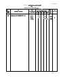
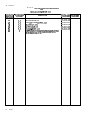
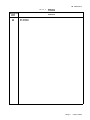
1
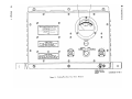
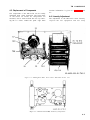
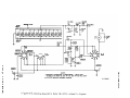
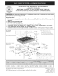
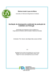
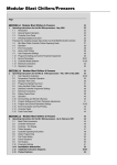
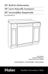
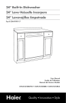
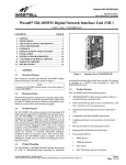
TM 11-6625-333-15
TECHNICAL MANUAL
OPERATOR’S, ORGANIZATIONAL, DIRECT SUPPORT, GENERAL SUPPORT,
AND DEPOT MAINTENANCE MANUAL
STANDING-WAVE-RATIO
POWER METER
ME-165/G
(NSN 6625-00-682-4464)
This copy is a reprint which includes current
pages
from
HEADQUARTERS,
Changes
1
through
3.
DEPARTMENT
OF
THE
ARMY
MARCH 1971
The following are general safety precautions that are not related to
any specific procedure and, therefore, do not appear elsewhere in this publication. These are recommended precautions that personnel must understand and apply during many phases of operation and maintenance.
Operator and maintenance personnel should be familiar with the
safety requirements before attempting installation or operation
of the equipment covered by this manual.
Failure to follow requirements and observe safety precautions
could result in injury or damage to the equipment.
For the successful execution of methods of equipment destruction
involving the use of demolition materials, all personnel should
become thoroughly familiar with the pertinent provisions of
FM 5-25.
*TM 11-6625-333-15
T ECHNICAL M A N U A L
HEADQUARTERS
DEPARTMENT OF THE ARMY
W ASHINGTON , DC 5 March 1971
No. 11-6625-333-15
OPERATORS, ORGANIZATIONAL, DIRECT SUPPORT, GENERAL SUPPORT
AND DEPOT MAINTENANCE MANUAL
STANDING-WAVE-RATIO POWER METER ME-165/G
(NSN 6625-00-682-4464)
REPORTING ERRORS AND RECOMMENDING IMPROVEMENTS
You can help improve this manual. If you find any mistakes or if you know of a way
to improve the procedures, please let us know. Mail your letter, DA Form 2028
(Recommended Changes to Publications and Blank Forms), or DA Form 2028-2
located in back of this manual direct to: Commander, US Army Communications and
Electronics Materiel Readiness Command, ATTN: DRSEL-ME-MQ, Fort Monmouth NJ 07703.
In either case, a reply will be furnished direct to you.
Table of Contents
C HAPTER 1 .
2.
C HAPITER 3.
SECTION I.
II.
C HAPTER 4.
C HAPTER 5 .
SECTION I.
II.
C HAPTER 6 .
7.
A PPENDIX A .
B.
C.
IN D E X
Paragraph Page
INTRODUCTION
1.1 - 1-5 1-1
INSTALLATION AND OPERATING INSTRUCTIONS
2-1 - 2-4 2-1
OPERATOR AND ORGANIZATIONAL MAINTENANCE
Operator maintenance.. . . . . . . . . . . . . . . . . . . . . . . . . . . . . . . . . . . . . . . . . . . . . . . . . . . . . . . . . . . . . . . .. . . . . . . . . 3-1 - 3-8 3-1
O r g a n i z a t i o n a l m a i n t e n a n c e. . . . . . . . . . . . . . . . . . . . . . . . . . . . . . . . . . . . . . . . . . . . . . . . . . . . .3.9 - 3-12 3-3
DIRECT AND GENERAL SUPPORT MAINTENANCE . . . . . . . . . . . . . . . . . . . . . . . . . . . . . . . . ..4-1 - 4-6 4-1
DEPOT MAINTENANCE AND DEPOT OVERHAUL STANDARDS
D e p o t m a i n t e n a n c e . . . . . . . . . . . . . . . . . . . . . . . . . . . . . . . . . . . . . . . . . . . . . . . . . . ... . . . ..5-1, 5-2 5-1
Depot overhaul standards . . . . . . . . . . . . . . . . . . . . . . . . . . . . . . .. . . . . . . . . . . . . . . . . . . . . . . . . . . . . . ..5-3 - 5-6 5 - 1
FUNCTIONING OF EQUIPMENT . . . . . . . . . . . . . . . . . . . . . . . . . . . . . . . . . . . . . . . . . . . . . . . . . . . . . ..6-1, 6-2 6-1
STORAGE AND DEMOLITION OF EQUIPMENT . . . . . . . . . . . . . . . . . . . . . . . . . . . . . . . . . . . . . ..7-1 -7-6 7 - 1
REFERENCES . . . . . . . . . . . . . . . . . . . . . . . . . . . . . . . . . . . . . . . . . . . . . . . . . . . . . . . . . . . . . . . . . . . . . . . . . . . . . . . . . . . ..A-1
BASIC ISSUE ITEMS LIST (BIIL) AND ITEMS TROOP INSTALLED OR AUTHORIZED
LIST (ITIAL) (Not Applicable)
MAINTENANCE ALLOCATION . . . . . . . . . . . . . . . . . . . . . . . . . . . . . . . . . . . . . . . . . . . . . . . . . . . . . . . . . . . . . . . . . . ..C-1
. . . . . . . . . . . . . . . . . . . . . . . . . . . . . . . . . . . . . . . . . . . . . . . . . . . . . . . . . . . . . . . . . . . . . . . . . . . . . . . . . . . . . . . . . . . . . . . . . . . . . . I-1
This manual supersedes TM 11-809-10, 14 May 1958 including all changes, TM 11-809-20, 2 July 1958 and TM 11-809-35, 3
December 1958 as pertains to subject equipment.
C h a n g e
2
i
TM 11-6625-333-15
CHAPTER 1
INTRODUCTION
1-1. Scope
This manual describes Standing-Wave-Ratio
Power Meter ME-165/G (fig. 1-1) and covers
installation, operation, and maintenance instructions. Appendix A contains a list of publications
applicable to this manual and Appendix C
contains the maintenance allocation chart.
1-2. Indexes of Publications
a. DA Pam 310-4. Refer to the latest issue of DA
Pam 310-4 to determine whether there are new
editions, changes, or additional publications pertaining to the equipment.
b. DA Pam 310-7. Refer to DA Pam 310-7 to
determine whether there are modification work
orders (MWO’s) pertaining to the equipment.
1-3. Maintenance Forms, Records, and
Reports
a. Reports of Maintenance and Unsatisfactory
E q u i p m e n t . Department of the Army forms and
procedures used for equipment maintenance will
be those described by TM 38-750, The Army
Maintenance Management System.
b. Report of Packaging and Handling Deficiencies. Fill out and forward DD Form 6 (Packaging
Improvement Report) as prescribed in AR 70058/NAVSUPINST 4030.29/AFR 71-13/MCO
P4030.29A and DLAR 4145.8.
c. Discrepancy in Shipment Report (DISREP)
(SF 361). Fill out and forward Discrepancy in
Shipment Report (DISREP) (SF 361) as prescribed
in AR 55-38/NAVSUPINST 4610.33B/AFR 75-18/
MCO P4610.19C and DLAR 4500.15.
1-3.1. Reporting Equipment Improvement
Recommendations (EIR)
If your Standing-Wave-Ratio Power Meter ME165/G needs improvement, let us know. Send us an
EIR. You, the user, are the only one who can tell us
what you don’t like about your equipment. Let us
know why you don’t like the design. Tell us why a
procedure is hard to perform. Put it on an SF 368
(Quality Deficiency Report). Mail it to Commander,
US Army Communications and Electronics
Materiel Readiness Command, ATTN: DRSEL-
ME-MQ, Fort Monmouth, NJ 07703. We’ll send you
a reply.
1-3.2. Administrative Storage
Administrative storage of equipment issued to and
used by Army activities shall be in accordance with
TM 740-90-1.
1-3.3. Destruction of Army Electronics
Materiel
Destruction of Army electronics materiel to prevent enemy use shall be in accordance with TM
750-244-2.
1-4. Description of Standing-Wave Ratio
Power Meter ME-165/G
a. The ME-165/G is used for measuring transmitter output power and standing-wave-ratio; it may
also be used for terminating the transmitter
during radio silence operation.
b. All components of the ME-165/G are mounted
on the front panel which fastens into a louvered
case with 10 screws. The rear of the case has a
flange on top and a bracket on the bottom to permit
wall mounting (fig. 1-2).
c. The unit is 13-1/2 inches by 9-5/8 inches by 9-5/8
inches, and has a gray, smooth finish. A wingnut
on the bottom of the case secures a ground braid.
1-4.1. Component Comprising the Operable
End Item
Standing Wave Ratio-Power Meter ME-165/G
(FSN 6625-682-4464) comprises the operable end
item.
1-5. Differences in Equipments
a. Standing-Wave-Ratio Power Meters ME165/G, procured on Order Numbers 3219-Phila.-59
and 3241-Phila.-59, are similar in appearance,
operation, and purpose to those procured on
previous orders. They differ only in some piecepart reference designations which are outlined in
the chart below:
NOTE
All reference designations not listed in
the chart are identical for all units.
Change 2
1-1
Change 1
TM 11-6625-333-15
1-2
Figure 1-1.
TM 11-6625-333--15
Figure 1-2. Standing-Wave-Ratio Power Meter ME-165/G
mounted on wall of shelter.
All orders prior to No. 3219-PP-59 Order No. 3219-PP-59 and 3241-PP-59
Component
C3
C4
C5
C6
C7
C8
C9
C10
CR1
CR2
R13
R14
R15
R16
R17
Component
C4
C5
C6
C7
C8
C1
C2
C3
CR2
CR1
R20
R21
R13
R22
R23
All orders prior lo No. 3219-PP-59 Order No. 3219-PP-59 and 3214-PP-59
Component
R18
R19
R20
R21
R22
R23
Component
R14
R15
R16
R17
R18
R19
b.
Standing-Wave-Ratio
Power
Meter
ME-165/G procured on
Numbers
Order
3219-PP-59 and 3241-PP-59 indicate powcr on
the upper meter scale and SWR on the lower
scale; those procured on other order numbers
indicate power on the lower meter scale and
standing wave ratio on the upper meter scale.
1-3
TM 11-6625-333-15
CHAPTER 2
INSTALLATION AND OPERATING INSTRUCTIONS
NOTE
The ME-l65/G is designed as a ready-to-go equipment; therefore, detailed unpacking
procedures do not apply.
2-1. Checking Unpacked Equipment
a. Inspect the equipment for damage that may
have been incurred during shipment. If the unit has
been damaged, fill out and forward DD Form 6.
b. Check to see that the equipment is complete as
Iisted on the packing slip. Report all discrepancies in
accordance with TM 38-750.
NOTE
Shortage of a minor assembly or part that
does not affect proper functioning of the
equipment should not prevent use of the
equipment.
c. If the equipment has been used or reconditioned,
check to see whether it has been changed by a
modification work order (MWO). If the equipment
has been modified, the MWO number should appear
on the front panel near the nomenclature plate.
Check to see whether the MWO number (if any) and
appropriate notations concerning the modifications
have been written into the equipment manuals.
NOTE
Current MWO’s applicable to the equipment are listed in DA Pam 310-7.
2-2. Controls and Indicators
(fig. l-l)
The designation and function of the various controls
and indicators of the ME-165/G are described in the
chart below.
Function
Control or indicator
POWER
.
.
.
.
.
.
.
Connects transmitter power output to dummy load; power output of transmitter is indicated
on meter.
Control or indication
Function
ADJUST . . . . . . . . Used in conjunction with ADJUST rotary control to
calibrate m e t e r f o r v s w r
measurements.
SWR . . . . . . . . . . . . . . . . . . . . . . . . .Used to indicate vswr between
transmitter and its load.
OPERATE. . . . . . . . . . . Connects power output of transmitter directly to load.
ADJUST rotary control . . Used in conjunction with function switch to calibrate meter
for vswr measurements.
INPUT connecter . . . . Used as conception for amplifier
input.
OUTPUT connector . . . . . Used to apply rf output to radio
set antenna.
METER . . . . . . . . . . . . . . . Provides visual indication of
average output power in watts,
or vswr depending on position
of function switch.
2-3. Tuning Procedures
CAUTION
If the transmitting antennas of two or
more radio sets are close together, coordinate tuning operations so that one radio
set is not transmitting while the function
switch of the ME-165/G in the other radio
set is set to SWR. Power radiated from a
nearby antenna can burn out the dummy
load resistor in the ME-165/G.
a. Place the ME-165/G function switch at POWER
b. Tune and load the transmitter in accordance
with standard operating procedures.
c. Note that the ME-165/G indicates the transmitter power output.
Change 1
2-1
TM 11-6625-333-15
When the function switch is set to
POWER, ADJUST, or SWR, full transmitter output power is dissipated in the
dummy load of the ME-165/G. Do not
apply power continuously for longer
than 10 minutes or the unit may be damaged.
h. Set the function switch to OPERATE to
connect the output of the transmitter directly to
the antenna tuning unit.
2-4 Operational Procedures
d. S e t t h e M E - 1 6 5 / G f u n c t i o n s w i t c h t o
ADJUST.
Since the ME-165/G can be operated in various
modes, the particular mode of operation and the
average power indications to be observed are as
follows :
e. Rotate the ADJUST rotary control to obtain
a full-scale indication.
a. Continuous wave (cw) _ Approximately 200
watts.
NOTE
Do not keep the control in the ADJUST
position any longer than necessary for
meter adjustment.
f. Set the function switch to SWR.
g. Observe that the proper standing wave ratio
between the transmitter and tuning unit is
reflected on the upper scale (green area) of the
meter.
2-2
Change 1
b. Single sideband (ssb) _ _ Approximately 200
watts.
c. Compatible amplitudemodulated (am. )
Approximately 200
watts.
d. Frequency shift keying Approximately 200
watts.
(fsk)
e. Voice plus fsk _ _ _ _ _ _ _ _ Approximately 100
watts.
TM 11-6625-333-15
CHAPTER 3
OPERATOR AND ORGANIZATIONAL MAINTENANCE
Section I.
OPERATOR MAINTENANCE
3-1. Scope of Operator Maintenance
The maintenance duties assigned to the operator
of the ME-165/G are listed below together with a
reference to the paragraphs covering the specific
maintenance function.
a. Daily preventive maintenance checks and
services (para 3-5).
b. Cleaning (para 3-6).
c. Troubleshooting (para 3-7).
d. Touchup painting (para 3-8).
3-2. Tools, Materials, and Test Equipment
Required
The only tools and test equipment required for
operator maintenance are those furnished as part
of the ME-165/G. The required materials are as
follows :
a. Trichloroethane.
b. Cloth, textile: cheesecloth, lint-free (FSN
8305-267-3015).
c. Abrasive sheet (FSN 5350-271-7939).
3-3. Operator Preventive Maintenance
tematic care and cleaning essential to proper
upkeep and operation of the equipment.
b. Preventive Maintenance Checks and Services.
The preventive maintenance checks and services
chart (para 3-5) outlines functions to be performed at specific intervals. These checks and
services are to maintain electronic equipment in a
combat-serviceable condition; that is, in good general (physical) condition and in good operating
condition. To assist operators in maintaining
combat serviceability, the chart indicates what to
check, how to check, and the normal conditions;
the References column lists the illustrations, paragraphs, or manuals that contain detailed repair or
replacement procedures. If the defect cannot be
remedied by the operator performing the corrective actions listed, higher category maintenance
or repair is required Records and reports of these
checks and services must be made in accordance
with the requirements given in TM 38-750.
3-4. Preventive Maintenance Checks
and Services Periods
Preventive maintenance checks and services of
the ME-165/G are required daily by the operator.
Paragraph 3-5 specifies the checks and services
that must be accomplished daily and under the
conditions listed below:
Preventive maintenance is the systematic care,
servicing, and inspection of equipment to prevent
the occurrence of trouble, to reduce downtime,
and to assure that the equipment is serviceable.
b. When the equipment is reinstalled after
removal for any reason.
a. Systematic Care. The procedures given in
paragraphs 3-4 through 3-8 cover routine sys-
c. At least once each week if the equipment is
maintained in standby condition.
a. When the equipment is initially installed.
3-5. Operator Daily Preventive Maintenance Checks and Services Chart
Item to be inspected
Procedure
References
1
Completeness . . . . . . . . . . . . . . . . . . . . . . . .
Check to see that equipment is complete.
App B.
2
Exterior surfaces . . . . . . . . . . . . . . . . . . . Clean exterior surfaces of equipment_ _ _ _ _
3
Connectors . . . . . . . . . . . . . . . . . . . . . . . .
Sequence No.
Check tightness of all power connectors.
Fig. 1-1.
Fig. 1-1.
3-1
TM 11-6625-333-15
3-5. Operator Daily Preventive Maintenance Checks and Services Chart (cont.)
Sequence
4
5
6
7
8
No.
Item
to
be
inspected
Procedure
Signal cables and wires . . . . . . . . . . . . . . . . . . Inspect cables for fraying or damaged insulation.
Inspect for defective connections with strained
wires. Tighten any loose plugs and connections.
mechanical action of each jack by inserting a
Jacks . . . . . . . . . . . . . . . . . . . . . . . . . . . . . . . . . . .Inspect
.
plug.
Hardware . . . . . . . . . . . . . . . . . . . . . . . . . . . . . . .Make sure that all threaded hardware is not nicked,
burred, or otherwise marred.
Controls and indicators . . . . . . . . . . . . . . . . . While making the operating checks (sequence No. 8),
observe that mechanical action of each knob, dial,
and switch is smooth and free of external or
internal binding and that no excessive looseness
exists.
Operation . . . . . . . . . . . . . . . . . . . . . . . . . . . . . . .Operate equipment according to appropriate
instructions. Report any operational failure of
equipment. Replace defective items for which
running spares are authorized.
3-6. Cleaning
Inspect the exterior of the equipment. The exterior
surfaces should be clean, and free of dust, dirt,
grease, and fungus.
a. Remove dust and loose dirt with a clean, soft
cloth.
Adequate ventilation should be provided
TRICHLOROTRIFusing
while
LUOROETHANE. Prolonged breathing of
vapor should be avoided. The solvent
should not be used near heat or open flame;
the products of decomposition are toxic and
irritating. Since TRICHLOROTRIFLUOROETHANE dissolves natural oils,
prolonged contact with skin should be
avoided. When necessary, use gloves which
the solvent cannot penetrate. If the solvent
is taken internally, consult a physician
immediately.
b. Remove grease, fungus, and ground-in dirt from
the equipment case; use a cloth dampened (not wet)
with trichloroethane.
c. Remove dust or dirt from plugs and jacks with a
brush.
CAUTION
Do not press on the meter face (glass) when
cleaning, the meter may become damaged.
d. Clean the front panel, meter, and control knobs
with a soft, clean cloth. If dirt is difficult to remove,
3 - 2 Change 2
References
Fig. 1-1
dampen the cloth with water; mild soap may be used
for more effective cleaning.
e. Remove dust from around terminal boards and
other small components by using a properly shaped
brush to loosen the accumulation. If available, dry
compressed air may be used at a line pressure not to
exceed 60 pounds-per-square inch (psi) to remove
dust from inaccessible places; however, be careful or
mechanical damage from the airblast may result.
3-7. Operator Troubleshooting
Whenever an equipment trouble occurs, make a
visual inspection of all equipment controls and cable
connections before performing any detailed troubleshooting procedures. The following visual checks
should be made by the operator to determine the
possible cause of malfunction.
a. Check all equipment controls for proper positioning.
b. If necessary, check to see that all signal and
power cable arrangements are correctly located and
secure.
c. Perform other visual checks as indicated in the
appropriate technical manuals (app A).
d. If the trouble is not apparent, or the above
checks do not reveal the cause of malfunctioning,
higher category maintenance is required.
3-8. Touchup Painting Instructions
Clean rust and corrosion from metal surfaces by
lightly sanding them with fine sandpaper. Brush
TM 11-6625-333-15
two thin coats of paint on the bare metal to
protect it from further corrosion Refer to the
Section II.
applicable cleaning and refinishing practices specified in TB 746-10.
ORGANIZATIONAL MAINTENANCE
3-9. Organizational Preventive Maintenance
a. Preventive maintenance is the systematic
care, inspection, and servicing of equipment to
maintain it in serviceable condition, prevent
breakdowns, and assure maximum operational
capability. Preventive maintenance is the responsibility of all categories of maintenance concerned
with the equipment and includes the inspection,
testing, and repair or replacement of parts, subassemblies or units that inspection and tests indicate would probably fail before the next scheduled
periodic service. Preventive maintenance checks
and services of the equipment at the organizational category of maintenance are made at
monthly intervals unless otherwise directed by the
commanding officer. The preventive maintenance
checks and services should be scheduled concurrently with the periodic service schedule of the
carrying vehicle for all vehicular installations.
b. Maintenance forms and records to be used
and maintained on this equipment are specified in
TM 38-750.
3-10. Monthly Maintenance
Perform the maintenance functions indicated in
the monthly preventive maintenance checks and
services chart (para 3-11) once each month.
A month is defined as approximately 30 calendar days of 8-hour-per-day operation. If the
equipment is operated 16 hours a day, the
monthly preventive maintenance checks and
services should be performed at 15-day intervals. Adjustment of the maintenance interval
must be made to compensate for any unusual
operating conditions. Equipment maintained in a
standby (ready for immediate operation) condition must have monthly preventive maintenance
checks and services performed on it. Equipment
in limited storage (requires service before operation) does not require monthly preventive maintenance.
3-11. Organizational Monthly Preventive Maintenance Checks and Services Chart
Sequence
Item to be inspected
No.
References
Procedure
1
Publications
Check to see that all publications are
complete, serviceable, and current.
DA PAM 310-4.
2
Modifications
Check DA Pam 310-7 to determine if
new applicable MWO’s have been
published. All URGENT MWO’s must
be applied immediately. All NORMAL
MWO’s must be scheduled.
DA Pam 310-7 and TM 38-7
App A and B.
3
Spare parts
Check all spare parts (operator and organizational) for general condition and
method of storage. No overstock
should be evident and all shortages
must be on valid requisitions.
4
Equipment hardware
Tighten loose bolts, nuts, and screws
that hold equipment. Replace missing
bolts, screws, nuts, and washers. Replace all badly burred screws, bolts,
and nuts which cannot be engaged or
turned with a screwdriver or wrench.
5
Signal and power cables and cords _ _ _ _ _ _ Dress all cables and cords neatly.
6
Miscellaneous items
Check to see that all items not required
for immediate use are properly stored.
7
Cable layout
Inspect cable layout and relocate cables
as necessary so that they are not endangered by, and are not dangerous
to personnel.
50.
3-3
TM 11-6625-333-15
Sequence No.
8
Item to be inspected
Resistors and capacitors _ _ _ _ _ _ _ _
Procedure
Inspect for cracks, blistering, or other
detrimental defects. Inspect variable
capacitors for dirt, corrosion, or defor-
References
Fig. 4-2 and 4-3.
med plates.
3-12. Organizational Troubleshooting
Information
The troubleshooting and repair work that can be
performed at the organizational category of maintenance is necessarily limited in scope by the
3-4
tools, test equipment, and replaceable parts issue,
and by existing tactical situation. Accordingly,
troubleshooting is based on the performance of
the equipment and the use of the senses in deterlining such troubles as burned out components
and loose connections.
TM 11-6625-333-15
CHAPTER 4
DIRECT AND GENERAL SUPPORT MAINTENANCE
4-1. General Maintenance Instructions
a. The preventive maintenance procedures performed at direct and general support categories of
m a i n t e n a n c e a r e actions w h i c h h a v e b e e n
designed to anticipate potential problem areas for
the purpose of correcting a possible trouble before
it results in equipment outage. The action to be
taken consists mainly of the following:
(1) Visual inspection of the equipment for
the purpose of determining general condition,
unusual noise, and wear, and observing meter
indications. Generaily, the equipment will remain
operational when these inspections are made.
(2) Repair or replacement of parts that have
a definite life expectancy
b. The direct and general support maintenance
procedures are not complete in themselves but
supplement the procedures performed at the
organizational category and include any additional techniques required to perform maintenance cm the ME-165/G
4-2. Took, Materials, and Test Equipment
Required
a. The test equipment and materials required
for maintenance of the ME-165/G are listed in
the appropriate paragraphs in which the adjustment procedures are given. The specified test
equipment, or suitable equivalents, should be used
to comply with the requirements of this chapter.
across high-voltage circuits. Severe
burns or electrical shock to the user and
damage to the equipment under test may
result.
4-3. Troubleshooting Techniques
To be effective, troubleshooting must be systematic; it will be necessary to perform a sequence of
operational checks, observations, and measurements before the cause of a trouble is revealed.
a. The first step in servicing a defective equipment is to sectionalize the fault. Sectionalization
means tracing the fault to the major equipment
component. The second step is to localize the fault.
Localization means tracing the fault to the defective stage. The third step, isolation, means tracing
the fault to the defective part. Some faults, such
as burned-out resistors, can often be isolated by
sight, smell, or hearing. The majority of faults,
however, must be isolated by checking voltages,
resistance, and signal levels
b. After the trouble has been sectionalized, perform operational tests on the suspected section;
figure 4-1 illustrates the test setup. Operational
tests serve as a check of the sectionalizing test,
and may also be used to indicate whether or not
the unit is functioning properly.
4-4. Troubleshooting Procedures
NOTE
Before using the test equipment, carefully read the operating instructions.
For maximum accuracy in all measurements, use the range that will produce a
meter indication as close to midscale as
possible.
a. Localizing troubles to a defective part or
circuit in the ME-165/G is accomplished at direct
and general support categories of maintenance by
performing the bench test described in d b e l o w
until an abnormal condition is observed, noting
the trouble symptom, and performing the related
checks and corrective measures indicated in the
troubleshooting chart (d b e l o w ) .
h. When using test equipment, place it on a firm
support and position the test equipment so that its
controls are within easy reach.
NOTE
The ME-165/G must be recalibrated
after any repairs or adjustments,
D o N o t allow any test lead to drape
b. B e n c h t r o u b l e s h o o t i n g
requires the following:
the
ME-165/G
4-1
TM 11-6625-333-15
(1) 28-volt direct current (dc) power source
to power a radiofrequency (rf) power source.
(2) Telegraph key KY-116/U,or equivalent.
(3) A 51-ohm, ½-watt composition resistor,
(4) Wattmeter AN/URM-120.
(5) Necessary cable assemblies (such as,
Radio Frequency Cable Assembly CG-2340A/U,
or CG-2568A/U) to connect the equipment.
c. Connect the equipment as shown in figure 4-1
and perform the following:
(1) Set the ME-165/G function switch to
POWER.
(2) Adjust the transmitter for cw operation
at the lowest transmitting frequency.
(3) Key the transmitter.
(4) Compare the power indication on the
ME-165/G with the power indication on the AN/
URM-120; the indications should agree within 10
percent.
Trouble symptom
(5) Adjust the transmitter for cw operation
At the highest transmitting frequency.
(6) Key the transmitter.
(7) Compare the power indication on the
ME-165/G with the power indication on the AN/
URM-120; the indications should agree within 10
percent.
(8) Set the ME-165/G function switch to
ADJUST
(9) Key the transmitter and rotate the
ME-165/G ADJUST rotary control until the
meter indicates full scale.
(10) Set the ME-165/G function switch to
SWR.
(11) Key the transmitter and observe that he
ME-165/G meter does not indicate beyond the
mid point in the green segment of the dial.
d. The following chart specifies typical symptoms of equipment malfunction and procedures to
be followed in connecting these troubles:
Probable trouble
Checks and corrective measures
No ME-165/G power meter indication
on AN/URM-120-------------------
a. Defectivc diode CR1__________a.
Check CR1.
b. Defective R13, R16, or R17 ____ b. Check R13, R16, and R17 for open
circuit.
c. Defective capacitor C4__________ c. Check C4 for short circuit.
d. Defective function switch S1 -------- d. Check contacts and continuity of S1.
e. Defective Meter Ml___________ e. Check Ml by substitution
ME-165/G power indication not within 10
percent of AN/URM-120 power indication at low frequency end.
Meter linearity inaccurate at lower
frequencies________________________
Adjust meter linearity at low-frequency end.
ME-l65/G power indication not within 10
percent of AN/URM-120 power indication at high-frequency end.
Meter linearity inaccurate at higher
frequencies______________________
Adjust meter linearity at high-frequency end.
a. Defectivc diode CR2 ____________a. Check CR2.
No meter indication when function switch
is set to ADJUST --------------------- b. Defective R15, R22, or R23_________________b. Check R15, R22, and R23 for open
circuit.
c. Defective function switch S1 ----- c. Check contacts of switch S1.
Resistor R18, R19, or R21 open or
Measure resistance of R18, R19, R20,
Meter pointer reads beyond green segment
and R21.
of dial when function switch is set to
more than 3 percent out of tolerance.
Figure 4-1. Bench test setup diagram.
4-2
TM 11-6625-333-15
4-5. Replacement of Components
The components of the ME-165/G can be readily
identified upon visual inspection. The front panel
of the meter on which all components are
mounted, can be removed from the case by removing the 1 0 screws around the panel edge. Parts
location information is given in figures 4-2 and
4-3.
4-6. Linearity Adjustment
The adjustment of the ME-165/ G meter linearity
requires the test equipment and test setup
Figure 4-2. Standing-Wave-Ratio Power Meter ME-165/G interior view.
Figure 4-3. Terminal board TB2, location of components.
4-3
TM 11-6625-333-15
described in paragraph 4-4 and shown in figure
4-1. The 51-ohm terminating resistor shown in
figure 4-1 i S not required for this adjustment.
following adjustments: dangerous RF
voltages may be present.
f. If the ME-165/G power meter indication is
not correct within 5 percent, adjust ME-165/G
potentiometer R23 so that the power meter indicates the same power as the AN/URM-120
b. Connect the equipment as shown in figure
4-1.
g. Adjust the transmitter for cw operation at
the high frequency.
c. Set
POWER.
h. Key the transmitter and compare the power
indication on the ME-165/g with the power indication on the AN/URM-120; the indications
should agree within 5 percent.
the
ME-165/G
function
switch
to
d. Adjust the transmitter for cw operation at
the low frequency.
e. Key the transmitter and compare the power
indication on the ME-165/G with the power indination on the AN/URM-120 the indications should
agree within 5 percent.
Be extremely careful when making the
4-4
i. If the ME-165/G power meter indication is
not correct within 5 percent, adjust ME-165/G
capacitor C4 so that the power meter indicates the
same power as the AN/URM-120.
j. Repeat the procedures given in d through i
above, as necessary, until the ME-165/G power
meter indications are correct at both ends of the
frequency range.
TM 11-6625-333-15
CHAPTER 5
DEPOT MAINTENANCE AND DEPOT OVERHAUL STANDARDS
Section I.
DEPOT MAINTENANCE
5-1. General
Complete rebuild of the ME-165/G and/or its
individual components may be accomplished by
depot maintenance facilities when authorized.
5-2. Maintenance Procedures
a. Rebuild procedures of the ME-165/G will
include all repair, rebuild, replacement, and testing operations necessary to make the equipment
suitable for return to the Department of the
Army supply system stocks for reissue to using
organizations. Detailed procedures for accomplishing the repair and adjustments established in
the preceding portions of this manual and such
additional repair and rebuild operations as
deemed necessary, will be established by the maintenance facility performing the work.
b. Restore the appearance, performance, and
life expectancy of the ME-165/G to a standard
comparable to that of new equipment by performing the following procedures:
(1) Disassemble the unit as required.
(2) Inspect all component parts of the
ME-165/G.
(3) Repair or replace any worn or unserviceable part with a part that conforms to the original manufacturing specifications and tolerances.
(4) Reassemble the unit.
(5) Perform an operational test of the equipment.
Section II. DEPOT OVERHAUL STANDARDS
5-3. Applicability of Depot Overhaul
Standards
The tests outlined in this section are designed to
measure the performance capability of repaired
components that comprise the ME-165/G,
Because there are alternate methods to virtually
every type of operation, it must not be presumed
that the tests described will be satisfactory for
complete acceptance of the equipment. Rather, it
is the purpose to merely offer assistance and guidance in the most expedient method of determining
that the ME-165/G meets the minimum acceptable limit of system performance.
5-4. Applicable References
a. Technical publications applicable to the
ME-165/G are listed in appendix A. Applicable
procedures and standards of the depots performing these tests form a part of the requirement for
testing this equipment.
b. Perform all applicable MWO’s pertaining to
the equipment before making the tests specified.
DA Pam 310-7 lists all current MWO’s.
5-5. Physical Tests and Inspections
a. Inspect the front panel for damaged, loose, or
missing screws, k n o b s , o r o t h e r p a r t s . T h e r e
should be no evidence of damage or loose components.
b. Inspect the chassis for signs of excessive
wear or damage, missing components, or hardware.
c. Inspect the condition of finish Check for rust
and corrosion. The external surfaces should not
show bare metal and all front panel lettering
should. be legible.
Touchup painting is recommended
instead of refinishing. Screwheads and
receptacles should not be polished with
abrasives.
5-1
TM 11-6625-333-15
d. Operate each control on the front panel. All
controls should operate smoothly with positive
action to indicated positions.
5-6. Calibration Procedures
The following procedures apply to
No.
Order
procured on
models
3219-PP-59,
3241-PP-59,
and
later.
Resistor R17 and capacitor C3 are used to adjust
the accuracy of the ME-165/G in power measurements. Remove the front panel from the case and
proceed as follows:
a. Connect Wattmeter AN/URM-120 between
the RF OUTPUT receptacle and the INPUT
connector on the ME-165/G.
b. Set up the equipment for cw operation at
some frequency between 1.5 and 2 megacycles
(mc).
c. S e t t h e M E - 1 6 5 / G f u n c t i o n s w i t c h t o
POWER.
5-2
d. Key
the
transmitter.
e. Compare the power indications on the AN/
URM-120 and the ME-165/G.
NOTE
The power indications should agree
within 5 percent.
f. If necessary, adjust resistor R17
power indications agree (e above).
until
both
CAUTION
Be extremely careful when adjusting
resistor R17; dangerous RF voltages
may be present.
g. S e t u p t h e e q u i p m e n t f o r o p e r a t i o n a t
approximately 19 mc.
h. Key the transmitter and compare the power
indications
on
the
AN/URM-120
and
the
ME-165/G.
i. If necessary, adjust capacitor C3 until both
power indications agree within 5 percent.
j. Repeat the procedure outlined in a through i
above until the power indications are correct at
both ends of the transmitter frequency range.
TM 11-6625-333-15
CHAPTER 6
FUNCTIONING OF EQUIPMENT
6-1. General
a. Impedance matching a load to its source is an
important consideration in transmission systems.
If the load and source are mismatched, part of the
power is reflected back along the transmission line
toward the source. This reflection not only prevents maximum power transfer, but also can be
responsible for erroneous rneasurements of other
parameters, or even cause circuit damage in
high-power applications.
b. The power reflected from the load interferes
with the incident (forward) power causing standing waves of voltages and current to exist along
the line. The ratio of standing-wave maxima to
minima is directly related to the impedance mismatch of the load; therefore the standing-wave
ratio (swr) provides the means of determining
impedance and mismatch.
c. The matching unit of the ME-165/G, as
shown in figure 6-1, provides a noninductive
dummy load of 52 ohms and, when conneeted
between the transmitter and its load, permits
direct readings of the transmitter power output
and the swr between the transmitter and its load.
6-2. Detailed Circuit Analysis
(fig. 6-1)
a. The ME-165/G is used during preliminary
tuneup to eliminate transmitter damage because
of impedance mismatch, to permit optimum match
between the transmitter and the antenna, and to
keep the transmitter off the air until the tuneup is
complete. During normal operation, the transmitter RF is applied directly through the ME-165/G
to the antenna.
b. When function switch S1 is set to POWER,
ADJUST, or SWR, 12 600-ohm resistors (Rl
through R12), connected in parallel, are used as a
dummy load. When the function switch is set to
OPERATE, the transmitter is connected directly
through the ME-165/G to the antenna (a a b o v e ) .
c. The dummy load has an swr of 1.1 to 1, or
less, at frequencies up to 30 megacycles. Capacitors C2 and C3 provide balance and bypass rf
from the insulated resistor mounting plates to
ground. Capacitor Cl is connected to the input
line to compensate for wiring inductance.
d. When the function switch is set to POWER,
power is applied thrrough contacts 6 and 2 of
switch S1 (A), to the dummy load consisting of
resistors R1 through R12 and voltage-divider
resistors R20 and R21. Variable capacitor C4 is
connected across resistor R20 and is used to
adjust the meter linearity at higher frequencies.
From the junction of variable capacitor C4 and
resistor R20, the circuit to meter Ml is completed
through diode CR2, resistor R22, potentiometer
R23, and contacts 8 and 12 of switch S1 (C).
Capacitor C5 is a filter capacitor for diode CR2.
Potentiometer R23 is used to adjust meter linearity at the lower frequencies. The lower scale of
meter Ml indicates the RF power directly in
watts, and the upper scale indicates the swr.
Capacitor C8 is an RF bypass capacitor.
e. When the function switch is set to ADJUST,
power is applied to the dummy 1oad described
in d above. It is also applied through contacts 12
and 9 of switch S1 (A) and resistor R13 to a
bridge circuit consisting of resistor R14, capacitor
C6, resistors R15, R16, and R17, and diode CR1.
From the junction of diode CR1 and capacitor C6,
the voltage is applied through filter resistor R18
and capacitor C7 to ADJUST potentiometer R19.
Potentiometer R19 controls the amount of voltage
applied to meter M1 and allows the meter to be
adjusted to full scale for swr calibration purposes.
f. When the function switch is set to SWR,
power is applied to the dummy load, resistor R13,
and the bridge circuit as described in e a b o v e .
Also, one leg of the bridge circuit (at the junction
of resistor R14 and capacitor C6) is connected
through contacts 6 and 4 of switch S1 (C) to
OUTPUT jack J2 and the normal transmitter
6-1
TM 11-6625-333-15
load. The swr ratio is read on the upper scale of
the meter.
g. When the function switch is set to OPER-
6-2
ATE, a direct connection is made between INPUT
jack J1 and OUTPUT jack J2 through contacts 6
and 5 of switch S1 (A).
3
Figure 6-1.
6-3/6-4 (BLANK)
TM 11-6625-333-15
Change
TM 11-6625-333-15
CHAPTER 7
STORAGE AND DEMOLITION OF EQUIPMENT
7-1. Limited Storage Instructions
7-4. Destruction Plan
Repackaging of the ME-165/G for limited storage normally will be performed at a packaging
facility, or by a packaging team. The extent, of
equipment preparation or repackaging is determined by the length of time during which the
ME-165/G will remain inactive. Extensive
repackaging is required for extended storage, and
minimum packaging and protective measures are
required for short-time storage. Repackage the
equipment in accordance with the original packaging methods as far as possible with the available materials.
Any formulated destruction plan must be
complete, adequate, and capable of being easily
carried out under field conditions as available
time and personnel will permit. Personnel should
be assigned specific tasks so that minimum time
will be required if destruction becomes necessary.
Because the time required for complete destruction of the equipment may not always be available, destruction priorities should be established to
insure that essential parts of equipments will be
destroyed first.
7-5. Degree of Damage
7-2. Method of Storage
Storage normally refers to the placement of materiel in a building or covered structure and is classified as follows:
a. Class A storage is a building or closed structure which is heated and designed to afford protection from the elements.
b. Class B storage is a closed structure or building which is designed to afford protection from
the elements but is not heated.
c. Class C storage is a structure in which the
atmosphere is maintained at a specified relative
humidity by mechanical or electrical colitz-oiled
humidity devices.
A surveillance inspection (visual examination) is required of packing, packaging, and preservation for evidence of
damage or deterioration of the equip.
ment on a daily basis.
7-3. Authority for Demolition
Demolition of the ME-165/G will be accomplished
only upon order of the commander. The destruction procedures in paragraph 7-5 and 7-6 will be
used to prevent further use of the equipment.
When capture or abandonment of the ME-165/G
to an enemy is imminent, the responsible unit
commander must make the decision to either
destroy the equipment or render it inoperative.
a. Destruction of the ME-165/C and essential
spare parts must be so complete that it will be
impossible to restore the equipment to a usable
condition either by repair or cannibalization.
b. All notes, instructions, or other written
material pertaining to function, operation, maintenance, or employment, including drawings or
parts lists, must be destroyed in a way that will
render them useless to the enemy. Ashes of
burned documents and literature must be sifted,
or otherwise checked, to insure complete destruction.
7-6. Methods of Destruction
The tactical situation and time available will
determine the method to be used when destruction
of equipment is ordered. Use any or all of the
following methods to destroy the equipment.
a. Smash the equipment control panel. Be sure
that the components within the equipment case
are destroyed.
b. Cut all power cables, signal lines, and cords,
Slash all component wiring.
7-1
TM 11-6625-333-15
c. Pile all technical manuals and operational
correspondence on the ground and burn them
completely.
d. If explosives are avaiable, use them to
destroy the ME-165/G. Follow the procedure for
actuating the explosive charge or type of grenade
used.
Be extremely careful with explosives and
incendiary devices. Use these items only
when the need is urgent.
e. If practical, dispose the equipment remains
in a ravine, river, stream, well, or lake to provide
water damage and concealment.
7-2
TM 11-6625-333-15
APPENDIX A
REFERENCES
Following is a list of applicable publications available to the operator and maintenance personnel of the
ME-165/G.
AR 380-5
Military Security.
DA Pam 310-4
Index of Technical Publications: Technical Manuals, Technical Bulletins, Supply
Manuals (Types 7, 8, and 9), Supply Bulletins, and Lubrication Orders.
DA Pam 310-7
US Equipment Index of Modification Work Orders.
FM 5-25
Explosives and Demolition.
Preservation, Packaging, Packing and Marking Materials, Supplies, and Equipment
SB 38-100
used by the Army.
TB 43-0118
Field Instructions for Painting and Preserving Electronics Command Equipment
Including Camouflage Pattern Painting of Electrical Equipment Shelters.
TM 740-90-1
Administrative Storage of Equipment.
TM 750-244-2
Procedures for Destruction of Electronics Materiel to Prevent Enemy Use (Electronics
Command).
Change 2 A-1/(A-2 blank)
TM 11-6625-333-15
APPENDIX C
MAINTENANCE ALLOCATION
Section I. INTRODUCTION
C-1. General.
This appendix provides a summary of the maintenance operations for ME-165/G. It authorizes
categories of maintenance for specific maintenance functions on repairable items and components and the tools and equipment required to
perform each function. This appendix may be used
as an aid in planning maintenance operations.
C-2. Maintenance Function.
Maintenance functions will be limited to and
defined as follows:
a. Inspect. To determine the serviceability y of an
item by comparing its physical, mechanical, and/or
electrical characteristics with established standards through examination.
b. Test. To verify serviceability and to detect
incipient failure by measuring the mechanical or
electrical characteristics of an item and comparing
those characteristics with prescribed standards.
c. Service. Operations required periodically to
keep an item in proper operating condition; i.e., to
clean (decontaminate), to preserve, to drain, to
paint, or to replenish fuel, lubricants, hydraulic
fluids, or compressed air supplies.
d. Adjust. To maintain, within prescribed limits,
by bringing into proper or exact position, or by
setting the operating characteristics to the
specified parameters.
e. Align. To adjust specified variable elements of
an item to bring about optimum or desired
performance.
f. Calibrate. To determine and cause corrections
to be made or to be adjusted on instruments or test
measuring and diagnostic equipments used in
precision measurement. Consists of comparisons of
two instruments, one of which is a certified
standard of known accuracy, to detect and adjust
any discrepancy in the accuracy of the instrument
being compared.
g. Install. The act of emplacing, seating, or fixing
into position an item, part, module (component or
assembly) in a manner to allow the proper
functioning of the equipment or system.
h. Replace. The act of substituting a serviceable
like type part, subassembly, or module (component
or assembly) for an unserviceable counterpart.
i. Repair. The application of maintenance services (inspect, test, service, adjust, align, calibrate,
replace) or other maintenance actions (welding,
grinding, riveting, straightening, facing, remachining, or resurfacing) to restore serviceability to an item by correcting specific damage,
fault, malfunction, or failure in a part, subassembly, module (component or assembly), end item, or
system.
j. Overhaul. That maintenance effort (service/
action) necessary to restore an item to a completely
serviceable/operational condition as prescribed by
maintenance standards (i.e., DMWR) in appropriate technical publications. Overhaul is normally
the highest degree of maintenance performed by
the Army. Overhaul does not normally return an
item to like new condition.
k. Rebuild. Consists of those services/actions
necessary for the restoration of unserviceable
equipment to a like new condition in accordance
with original manufacturing standards. Rebuild is
the highest degree of materiel maintenance
applied to Army equipment. The rebuild operation
includes the act of returning to zero those age
measurements (hours, miles, etc.) considered in
classifying Army equipments/components.
C-3. Column Entries.
a. Column 1, Group Number. Column 1 lists
group numbers, the purpose of which is to identify
components, assemblies, subassemblies, and modules with the next higher assembly.
b. Column. 2, Component/Assembly. Column 2
contains the noun names of components, assemblies, subassemblies, and modules for which
maintenance is authorized.
c. Column 3, Maintenance Functions. Column 3
lists the functions to be performed on the item
listed in column 2. When items are listed without
maintenance functions, it is solely for purpose of
having the group numbers in the MAC and RPSTL
coincide.
d. Column 4, Maintenance Category. Column 4
specifies, by the listing of a “worktime” figure in
the appropriate subcolumn(s), the lowest level of
maintenance authorized to perform the function
listed in column 3. This figure represents the active
time required to perform that maintenance func-
C-1
TM 11-6625-333-15
tion at the indicated category of maintenance. If
the number or complexity of the tasks within the
listed maintenance function vary at different
maintenance categories, appropriate “worktime”
figures will be shown for each category. The
number of task-hours specified by the “worktime”
figure represents the average time required to
restore an item (assembly, subassembly, component, module, end item or system) to a serviceable
condition under typical field operating conditions.
This time includes preparation time, troubleshooting time, and quality assurance/quality control time in addition to the time required to
perform the specific tasks identified for the
maintenance functions authorized in the maintenance allocation chart. Subcolumns of column 4
are as follows:
C - Operator/Crew
O - Organizational
F - Direct Support
H - General Support
D - Depot
e. Column 5, Tools and Equipment. Column 5
specifies by code, those common tool sets (not
individual tools) and special tools, test, and support
equipment required to perform the designated
function.
f. Column 6, Remarks. Column 6 contains an
alphabetic code which leads to the remark in
section IV, Remarks, which is pertinent to the item
C-2
opposite the particular code.
C-4. Tool and Test Equipment Requirements (Sect. Ill).
a. Tool or Test Equipment Reference Code. T h e
numbers in this column coincide with the numbers
used in the tools and equipment column of the
MAC. The numbers indicate the applicable tool or
test equipment for the maintenance functions.
b. Maintenance Category. The codes in this
column indicate the maintenance category allocated the tool or test equipment.
c. Nomenclature. This column lists the noun
name and nomenclature of the tools and test
equipment required to perform the maintenance
functions.
d. National/NATO Stock Number. This column
lists the National/NATO stock number of the
specific tool or test equipment.
e. Tool Number. This column lists the manufacturer’s part number of the tool followed by the
Federal Supply Code for manufacturers (5-digit) in
parentheses.
C-5. Remarks (Sect. IV).
a . R e f e r e n c e C o d e . This code refers to the
appropriate item in section II, column 6.
b. Remarks. This column provides the required
explanatory information necessary to clarify items
appearing in section II.
TM
SECTION
STANDING-WAVE-RATIO
(1)
(2)
GROUP
NUMBER
COMPONSNT/ASSEMBLY
00
STPNUWI3-WAVE-RATIO
POWER METER 142-165/G
11-6625-333-15
I I MAINTENANCE ALLOCATION CHART
FOR
POWER METER
ME-165/G
(4)
(3)
tvt41NTENANCE
FUNCTION
Inspect
Test
Replace
Repair
Repaf r
Overhaul
MAINTENANCE @I TEGORY
c
o
F
H
D
0.2
0.5
::;
0.8
2.0
(5)
TOOLS
ANo
EOPT.
6
1 thru 5
6
6
1 thru 5
1 thru 5
(6)
REMARKS
A
Change 2 C-3
TM
11-6625-333-15
SECTION III
TOOL
AND TEST EQUIPMENT REQUIREMENTS
FOR
STANDING-WAVE-RATIO POWER METER ME-165/G
‘CK)L OR TEST
EQUIPMENT
REF CODE
C-4
MAINTENANCE
CATEGORY
NOMENCtiTURE
NATIONAUNATO
STOCK NUMBER
6625-00-581-2036
1
H,D
MULTIMETER, AN). IRM-105
2
H,O
TOOL KIT, ELECTRONIC EQUIPMENT TK-105/G
5180-00-610-8177
3
H,D
MULTIMETER, TS-352B/U
6625-00-553-0142
4
H,D
WATTMETER, AN/U R14-120
6625-00-813-8430
5
H,O
TELEGRAPH , KEYER KY-116/U
5805-00-503-3395
6
0
Change 2
COWON TOOLS NECESSARY TO THE PERFORMANCE OF THIS MAINTENANCE
FUNCTION ARE AVAILABLE TO MAINTENANCE PERSONNEL FOR THIS
MAINTENANCE CATEGORY LISTED.
TOOL NUMBER
TM 11-6625-333-15
SECTION
IV.
REMARKS
REFERENCE
REMARKS
CODE
A
REPLACE KNOBS.
Change 2
C-5/(C-6 blank)
TM
11-6625-333-15
I-1
TM 11-6625-333-15
By Order of the Secretary of the Army:
Official:
KENNETH G. WICKHAM,
Major General, United States Army,
The Adjutant General.
W. C. WESTMORELAND,
General, United States Army,
Chief of Staff.
Distribution:
To be distributed in accordance with DA Form 12-51, organizational maintenance requirements
for AN/GRC-26 and AN/GRC-41 radio sets.
PIN : 017124-000
This fine document...
Was brought to you by me:
Liberated Manuals -- free army and government manuals
Why do I do it? I am tired of sleazy CD-ROM sellers, who take publicly
available information, slap “watermarks” and other junk on it, and sell it.
Those masters of search engine manipulation make sure that their sites that
sell free information, come up first in search engines. They did not create it...
They did not even scan it... Why should they get your money? Why are not
letting you give those free manuals to your friends?
I am setting this document FREE. This document was made by the US
Government and is NOT protected by Copyright. Feel free to share,
republish, sell and so on.
I am not asking you for donations, fees or handouts. If you can, please
provide a link to liberatedmanuals.com, so that free manuals come up first in
search engines:
<A HREF=http://www.liberatedmanuals.com/>Free Military and Government Manuals</A>
– Sincerely
Igor Chudov
http://igor.chudov.com/