1
PRO fORM
7,7.BEI
S
TAT
I O
N
._
R Y"
B
I K E
SWARS
Model No. 831.288250
Serial No.
Write the serialnumberin the space
above for futurereference.
Sedal
Number
't
_--X
E: R C
EQUIPMENT
I S
Decal
E:
HELPLINEI
1-800-72t6-6879
Patent Pending
SEARS, ROEBUCK AND CO., HOFFMAN
ESTATES, IL 60179
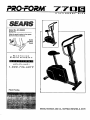
PRO'FORM
7 7 D
STATIONARY
,
BIKE
FULL 90 DAY WARRANTY
For 90 days from the date of purchase, if failure occurs due to defect in matedal or workmanship in this
SEARS BIKE EXERCISER, contact the nearest SEARS Service Center throughout the United States
and SEARS will repair or replace the BIKE EXERCISER, free of charge.
This warranty does not apply when the BIKE EXERCISER is used commercially or for rental purposes.
This warranty gives you specific legal rights, and you may also have other rights which vary from state
to state,
SEARS, ROEBUCK AND CO., DEPT. 817WA, HOFFMAN
2
ESTATES, IL 60179
I
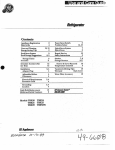
TABLE OF CONTENTS
FULL 90 DAY WARRANTY
..........................................
IMPORTANT PRECAUTIONS
..........................................
BEFORE YOU BEGIN ° . • *o ,. ° * ° ° . o.,
. . .,..
* • • ....
o , . ° ° ° ° o °
PART IDENTIFICATION CHART .....................................
ASSEMBLY ...........................................................................
HOW TO USE THE PROFORM 770S .......................................................
CONDITIONING GUIDELINES ............................................................
MAINTENANCE AND STORAGE ..........................................................
NOTES .............................................................................
PART LIST ...........................................................................
EXPLODED DRAWING ..........................................................
ORDERING REPLACEMENT PARTS ................................................
3
°
o .
°.•
o,°
";::..? _...'...:r..
_'.....
_,...................
, ,, ° • . ,>; ........
°.
*°
• °,
,.
' ......................
.:.'
3
4
5
6
8
10
12
13
14
.......
15
Back Cover
BEFORE YOU BEGIN
questions, please call our toll-free HELPLINE at
1-800-736-6879, Monday through Saturday, 7 a.m.
until 7 p.m. Central Time (excluding holidays). To help
us assist you, please note the product model number
and serial number before calling. The model number
is 831.288250. The sedal number can be found on a
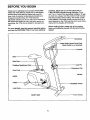
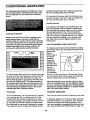
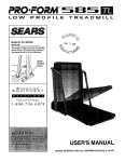
Thank you for selecting the innovative PROFORIVP
770S-The 770S offers a unique form of low-impact
exercise that works both the upper body and the
lower body for greater cardiovascular benefits end
increased muscle toning. The 770S features
adjustable resistance to let you tailor your exercise to
the level that's perfect for you. And when you're not
exemising, the 770S can be folded for compact stor-
decal attached to the 770S (see the front cover of this
manual for the location of the decal).
age.
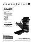
Before reading further, please look at the drawing
below and familiarize yourself with the parts that are
labeled.
For your benefit, read this manual carefully before
you use the PROFORM 770S. If you have additional
Handlebars
Holder/Towel Rack
(Water Bottle is not included)
Console
Seat
Seat Post
Lock Pin
Pedaling Resistance I
.Resistance Dial
Seat Knob
FRONT
BACK
Pedal
H_dle_rFmme
Lock Knob,
•Front Wheels
RIGHT SIDE
4
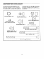
PART IDENTIFICATION CHART
Use the chart below for help identifying the small
parts used in assembly. The number in parenthesis
below each part refers to the key number of the part.
The number after the dash refers to the quantity used
in assembly. Note: :Some p.arts .K_a.
y r/av# been preattached for shipping purpos_:_ilf _;p;art is not
found in the parts bag, check;tt_ see If "Jr,
has been
pre-sttached.
O
M8 Nylon Locknut (46)--4
(May be attached to seat)
MIO Star Washer (14)--1
3/8' Nylon Locknut (56)--4
M12 OD Flat Washer (73)--2
Console Screw (12)--4
(May be attached to console)
M10 Flat Washer (57)--2
0
1/4" x 1" Screw (54)--2
_\\\\\\\}3/8' x 2 3/4" carriage Bolt (63)--2_
5/16" Flat Washer (26)--4
(May be attached to seat)
D
3/8" x 3 1/2" Screw (55)--2
3/8" x 6" Carriage Bolt (16)--1
5
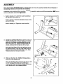
ASSEMBLY
Place all parts of the PROFORM 770S in a cleared area and remove the packing materials. Do not dispose of
the p_cidng materials until assembly Is completed.
In addition to the included allen wrenches _,
and two adjustable wrenches _;;=:::=::_3.
1.
assembly requires a phillips screwdriver
Refer to drawing 1A, Loosen the Lock Knob (38) on
the right side of the Frame (1).
IA
Refer to drawing 1. Slide the Handlebar Frame (2) forward until it stops.
2
Refer to drawing 1A. Tighten the Lock Knob (38)
2. Identify the Left Pedal (52); there is an %" on the Left
Pedal for identification. Using an adjustable wrench,
tighten the Left Pedal counterclockwise into the left
arm of the Crank (17). _ghten the Right Pedal (not
shown) clockwise into the right arm of the Crank.
\
2
Adjust the Pedal Strap (15) on the Left Pedal (52) to
the desired position. Press the Pedal Strap onto the
adjustment tab. Adjust the Pedal Strap on the Right
Pedal (not shown) in the same manner.
Adj
Tab
3, Make sure that there is a Stabilizer Endcap (45) on
each end of the Stabilizer (9).
52
56
Attach the Stabilizer (9) to the Frame (1) with two 3/8"
x 2 3/4" Carriage Bolts (63) and two 3/8" Nylon
Locknuts (56), Make sure that the Stabilizer is turned
so the dimples are in the indicated position.
6
45
,
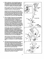
Refer to drawing 4A. The Console (58) requires two
"AA" batteries (not included). Alkaline batteries are
recommended. Press two battedes into the battery
clip under the Console. Make sure that the negative
(-) ends of the battedss are touching the epdngs.
4
58 _"
4A m
@
|
Ba_edes
Refer to drawing 4. Insert the console wire through
the Handlebar Post (4). Attach the Console (58) to the
Handlebar Post with four Console Screws (12).
wire
Connect the console wire to the Reed Switch Wire
(60) at the top of the Handlebar Frame (2). Insert the
Handlebar Post (4) into the Handlebar Frame. Be careful to avoid pinching the wires. Attach the Handlebar Post with two 3/8" x 3 1/2" Screws (55), two M10
Flat Washers (57), and two 3/8" Nylon Locknuts (56).
.
58
Refer to drawing 5. Remove the four round stickers
from the Handlebar Bracket (10) and the Handlebar
Post (4). Attach the Handlebar Bracket to the
Handlebar Post with two 1/4" x 1" Screws (54) and
the two M12 OD Flat Washers (73). Make sure that
the square hole is on the left side. Note: This step
shows how to assemble the Resistance Dial (11) on
the dght side of the Handlebar Post (4). To assemble
the Resistance Dial on the left side, reverse the orientation of the Resistance Bracket (10), 6" Carriage Bolt
(16), M10 Star Washer (14), and Resistance Dial.
Hold the lower end of the Left Handlebar (5) inside
the Handlebar Bracket (10). Insert the 3/8" x 6"
Carriage Bolt (16) into the Handlebar Bracket and
through the Left Handlebar. Hold the Right Handlebar
(6) inside the Handlebar Bracket_ Insert the Carriage
Bolt until the head of the Carriage Bolt is resting in
the square hole in the Handlebar Bracket. Slide the
57
5
M10 Star Washer (14) onto the Carriage Bolt. "13ghten
the Resistance Dial (11) onto the Carriage Bolt.
53
Align the holes in the Handlebars (5, 6) with the hole
in the Handlebar Post (4). Insert the Lock Pin (53)
through the Handlebars and the Handlebar Post. Be
careful not to damage the wire inside theHandlebar
Post.
6,
Insert the Seat Post (3) into the Frame (1). Align one
of the holes in the Seat Post with the hole in the
Frame. Insert the Seat Knob (37) into the Frame and
the Seat Post, and tighten the Seat Knob into the
Frame. Make sure to Insert the Seat Knob through
one of the holes In the Seat P'ost; do not Insert
the Seat Knob under the Seat Post.
Attach the Seat (36) to the Seat Post (3) with four M8
Nylon Locknuts (46) and four 5/16" Flat Washers (26).
(Note: The Nylon Locknuts and Flat Washers may be
preattached to the bottom of the Seat.)
7
16
6
37
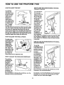
HOW TO USE THE PROFORM
770S
HOW-TO ADJUST THE SEAT
HOW TO USE THE HANDLEBARS
TIONARY POSITION
For effective
exercise, the
Seat (36) should
be at the proper
height. As you
pedal, there
should be a
The Handlebars
(5, 6) can be
used in either the
stationary position or the dualmotion position.
To use the
slight bend In
your knees when
the pedals are at
the lowest position. To adjust
the Seat, first
hold the Seat and unscrew the Seat Knob (37). Align
one of the holes in the Seat Post (3) with the hole in
the Frame (1). Insert the Seat Knob (37) into the
Frame and the Seat Post, and tighten the Seat Knob
into the Frame. Make sure to Insert the Seat Knob
through one of the holes in the Seat Post; do not
Insert the Seat Knob under the Seat Post.
Handlebars in the
stationary position, align the
holes in the
Handlebars with
the hole in the
Handlebar Post
(4). Insert the
Lock Pin (53)
through the
Handlebars and
the Handlebar
To adjust each
Pedal Strap (13),
first pull the end
of the Pedal
Strap off the
adjustment tab
on the Pedal
_)
Post. Note: If it is difficult to insert the Lock Pin, twist
the Handlebars slightly in order to align the holes.
Next, tighten the Resistance Dial (11) (see the drawing above).
HOW TO ADJUST THE PEDAL STRAPS
(51). Align a different hole in the
Pedal Strap with
the adjustment
tab. Press the
IN THE STA-
13
HOW TO USE THE HANDLEBARS
MOTION POSITION
IN THE DUAL-
To use the
Handlebars (5, 6)
in the dual-motion
position, remove
the Lock Pin (53)
from the
Handlebars and
the Handlebar
Tab
Pedal Strap onto the adjustment tab.
Post (4). Keep
the Lock Pin in a
safe place. The
resistance of the
Handlebars can
be adjusted with
the Resistance
T
HOW TO ADJUST THE PEDALING RESISTANCE
The pedaling
resistance can
be adjusted
using the
Resistance Knob
(40) located at
the base of the
seat post. To
increase the
Dial (11). To
increase the
resistance, turn
the Resistance Dial clockwise; to decrease the resistance, turn the
Resistance Dial counterclockwise.
resistance, turn
the Resistance
Knob clockwise; to decrease the resistance, turn the
Resistance Knob counterclockwise.
To exercise, move the Handlebars (5, 6) forward and
backward as you pedal. Be sure to keep your back
straight and your knees bent slightly.
8
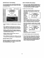
DESCRIPTION
OF THE CONSOLE
HOW TO 0PERA:rE tI'HE.CONSOLE
The console features five modes that provide instant
exercise feedback during your workouts. The modes
are described below.
f
1. To tum on the poWel', p{e_.the-'on/resl_t button or
atmply begin pedaling. When t_ powe'1"Is_umed
on, the entire display will e_ppe_rfor twq. seconds.
The consola will then be ready for operation.
2. Select one of the five modes:
Displa,
!.ede,ndicato
DIST,
CAL
Scan mode--When the power is turned on, the
scan mode will automaUcally be selected. One
mode indicator wifl show
that the scan
I /--t'FtCII
mode is
selected,
and a flash-
SCAN
AUTO OFF
=,,eeo[IL-'LrJ J
HEART
RATE
TRAINING
ZONES
ing mode
indicator will
show which
mode is currently displayed. Note: If a different
mode is selected, you can select the scan mode
again by repeatedly pressing the mode button.
• Speed_isplays
hour.
Speed, time, distance or calode mode--To select
one of these modes for continuous display, repeatedly press
the mode
button. The
mode indicators will
show which
mode is
selected.
(Make sure
that the scan mode is not selected.)
your pedafing speed, in miles per
• "lime--Displays the length of time you have exercised. Note: If you stop pedaling for ten seconds of
longer, the time mode will pause until you resume•
• Distance--Displays the total number of miles you
have pedaled, up to 999. The display will then reset
to zero and continue counting.
• Calorie---Displays the approximate number of
Calories you have bumed.
3. To reset the display, press the on/reset button.
.
• Scan--Displays the speed, time, distance, and calorie modes, for 5 seconds each, in a repeating cycle.
To turn off the power, simply wait for about four
minutes. Note: The cone_ole has an "auto-off"
feature. If the pedals are not moved and the
console buttons are not pressed for four minutes, the power will turn off autoinaUcally In
order to conserve the batteries. •
BATTERY INSTALLATION
Before the console can be operated, two "AA" batteries must be installed. If you have not installed batteries, see assembly step 4 on page 7.
9
CONDITIONING
GUIDELINES
The following general guideUnes will help you to plan
your exercise program. Remember that proper nutrition and adequate rest are essential for successful
results.
exercise until your heart rate is near the lowest number in your training zone as you exercise.
For maximum fat burning, adjust the intensity of your
exercise until your heart rate is near the middle number in your training zone as you exercise.
Aerobic Exercise
EXERCISEINTENSITY
Whether your goal is to burn fat or strengthen your
cardiovascular system, the key to achieving the
desi_d results is to exercise with the proper intensity.
The proper intensity level can be found by using your
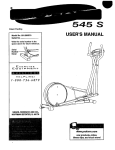
heart rate as a guide. The chart below shows recommended heart rates for fat burning, maximum fat
burning, and cardiovascular (aerobic) exercise.
HEART
RATE
TRAINING
If your goal is to strengthen your cardiovascular system, your exercise must be "aerobic." Aerobic exercise is activity that requires large amounts of oxygen
for prolonged periods of time. This increases the
demand on the heart to pump blood to the muscles,
and on the lungs to oxygenate the blood. For aerobic
exercise, adjust the intensity of your exercise until
your heart rate is near the highest number In your
training zone.
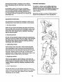
HOW TO MEASURE YOUR HEART RATE
To measure your heart rate, first exercise for at least
four minutes. Then, stop exercising and pisce two fingers on your
wdst as
shown. Take a
six-second
heartbeat
count, and
multiply the
result by 10 to
find your heart
rate. For
example, if
your six-second heartbeat
ZONES
count is 14, your heart rate is 140 beats per minute.
(A six-second count is used because your heart rate
will drop rapidly when you stoP exercising.)
To find the proper heart rate for you, first find your age
near the top of the chart (ages are rounded off to the
nearest ten years). Next, look below your age and
find the three numbers in grey boxes. The three numbers are your "training zone." The lowest number is
the recommended heart rate for fat burning; the middle number Is the recommended heart rate for maximum fat burning; the highest number is the recommended heart rate for aerobic exercise.
Adjust the intensity of your exercise until your heart
rate is at the desired level. You can adjust the intensity of your exercise by changing your pedaling speed,
adjusting the pedaling resistance, or using the handlebars in the dual-motion position.
Fat Burning
WORKOUT GUIDEUNES
To burn fat effectively, you must exercise at a relatively low intensity level for a sustained period of time.
Dudng the first few minutes of exercise, your body
uses easily accessible carbohydrate caiodes for energy. Only after the first few minutes of exercise does
your body begin to use stored fat calodes for energy.
If your goal is to bum fat, adjust the intensity of your
Each workout should include the following three parts:
A warm-up, lasting 5 tO 10 minutes. Begin with slow,
controlled stretches, and progress to more rhythmic
stretches to increase the body temperature, heart
rate, and circulation in preparation for strenuous exercise. (See SUGGESTED STRETCHES on page 11.)
10
Training zone exercise, consisting of 20 to 3_minutes of exercising with your heart rate in your training
zone.
A cool-down, with 5 to 10 minutes of stretching.
Thorough stretching helps to offset problems caused
when you stop exemising suddenly. Stretching for
increased flexibility is also most effective after exercising. A proper cool-down should leave you relaxed and
comfortably tired.
SUGGESTED
EXERCISE FREQI_IERC¥
To maintain or improve you_ Oond_!on;'pl_l}lthree
workouts each week_ with _t leas_ne da_ of'rest
between workouts. After a few mqnths of r_egularexercise, you may completeup
week, if desired.
to five Workouts each
Remember, the key to success is make exercise a
regular and enjoyable part of your everyday life.
STRETCHES
The correct form for several basic stretches is shown in the
drawings below. Move slowly as you stretch--never bounce.
1. Toe Touch Stretch
Stand with your knees bent slightly and slowly bend forward
from your hips. Allow your back and shoulders to relax as you
reach down toward your toes as far as possible. Hold for 15
counts, then relax. Repeat 3 times. Stretches: Hamstrings,
back of knees and back.
2
2. Hamstring Stretch
Sit with one leg extended. Bring the sole of the opposite foot
toward you and rest it against the inner thigh of your extended
leg. Reach toward your toes as far as possible. Hold for 15
counts, then relax. Repeat 3 times for each leg. Stretches:
Hamstrings, lower back and groin.
3
3. Calf/Achilles Stretch
With one leg in front of the other, reach forward and place
your hands against a wall. Keep your back leg straight and
your back foot fiat on the floor. Bend your front leg, lean forward and move your hips toward the wall. Hold for 15 counts,
then relax. Repeat 3 times for each leg. To cause further
stretching of the achilles tendons, bend your back leg as well.
Stretches: Calves, achilles tendons and ankles.
4. Ouaddceps
4
Stretch
With one hand against a wall for balance, reach back and
grasp one foot with your other hand. Bring your heel as close
to your buttocks as possible. Hold for 15 counts, then relax.
Repeat 3 times for each leg. Stretches: Quadriceps and hip
muscles.
5. Inner Thigh Stretch
Sit with the soles of your feet together and your knees outward. Pull your feet toward your groin area as far as possible.
Hold for 15 counts, then relax. Repeat 3 times. Stretches:
Quadriceps and hip muscles.
11
5
MAINTENANCE AND STORAGE
Inspe_ and tighten all parts of the PROFORM 770S
regularly. The 770S can be cleaned with a soft, damp
cloth. To prevent damage to the console, keep liquids
away from the console and keep the console out of
direct sunlight.
CRANKADJUSTMENT
BATTERY REPLACEMENT
of the slots in the Slotted Crank Nut (22). Ughtly tap
the screwdriver with a hammer to turn the Slotted
Crank Nut counterclockwise until the arms are no
longer loose. Do not overtighten the Slotted Crank
NuL When the Slotted Crank Nut is properly tightened, tighten the Crank Nut.
If the arms of the Crank (17) become loose, they
should be tightened in order to prevent excessive
wear. Loosen the Crank Nut (24) on the left arm of the
Crank, Place the end of a standard screwdriver in one
If the console does not function properly, the batteries
should be replaced. To replace the batteries, see
assembly step 4 on page 7.
HANDLEBAR
LUBRICATION
If a squeak is heard when the Handlebars (5, 6) are
moved, a small amount of grease should be applied.
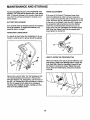
HOW'TO STORE THE PROFORM 770S
53
When the 770S is not in use, it can be folded for compact storage. Refer to the drawing below. Loosen the
Lock Knob (38). Slide the Handlebar Frame (2) into
the Frame (1) as far as it will go. "l]ghtan the Lock
Knob, Store the 770S indoors, away from moisture
and dust,
16
Remove the Lock Pin (53). Tum the Resistance Dial
(11) c_)unterclockwise and remove it. Remove the
M10 Star Washer (14). Using pliers, grip the head of
the 3/8" x 6" Carriage Bolt (16) and remove it. Apply a
thin film of grease to both sides of the Handlebar
Housings (72). Reattach all parts, making sure that
they are in the positions shown.
1
38
12
2
NOTES
13
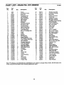
PART LIST--Model
Key
No.-
Part
No.
1
2
3
4
5
6
7
8
9
10
11
12
13
14
15
16
17
16
19
20
21
22
23
24
25
26
27
28
29
30
31
32
33
34
35
36
37
38
39
NSP
NSP
134372
134251
134371
134370
134254
134255
134256
134257
134258
013141
134259
104345
134260
134261
134377
122898
018001
019003
014009
012010
012011
012012
134263
014041
134374
134375
135426
127597
134266
132699
134267
134268
134269
134270
134271
134272
134273
Qty.
1
1
1
1
1
1
1
1
1
1
1
4
1
1
1
1
1
1
2
2
1
1
1
1
1
8
1
1
10
5
1
1
2
2
2
1
1
1
2
No. 831,288250
Description
Frame
Handlebar Frame
Seat Post
Handlebar Post
Left Handlebar
Right Handlebar
Idler Bracket
Idler Wheel
Stabilizer
Handlebar Bracket
Resistance Dial
Console Screw
Right Pedal Strap
M10 Star Washer
Left Pedal Strap
3/8" x 6" Cardage Bolt
Crank
Pulley
Bearing
Bearing Cup
Keyed Washer
718"Slotted Crank NUt
15/16" Slotted Crank NUt
7/6" Crank NUt
Rywheel Assembly
5/16" Rat Washer
Left Side Shield
Right Side Shield
Side Shield Screw
Fastener
Top Shield
Belt
Wheel Hub
Wheel
Wheel Bushing
Seat
Seat Knob
Lock Knob
Friction Pad
R1196A
Key
No.
Part
No.
Qty.
40
41
42
43
44
45
46
47
48
49
50
51
52
53
54
55
56
57
58
59
60
61
62
63
64
65
66
67
68
69
70
71
72
73
74
#
#
#
#
134274
124819
013225
109926
134275
134276
012042
134277
134278
134308
013576
134367
134368
109855
123713
123494
012149
014132
132827
134312
133472
128348
014008
122548
134314
119222
134316
134317
134366
012150
106106
013547
134376
125206
135425
134321
045028
100017
045017
1
2
1
1
2
2
7
1
1
1
1
1
1
1
2
2
5
2
1
1
1
1
1
2
1
1
2
1
2
2
1
1
1
2
1
1
1
1
1
Description
Tension Assembly
Handlebar Endcap
M5 Screw
Rubber Grommet
Foam Grip
Stabilizer Endcap
M8 Nylon Locknut
Handlebar Frame Bushing
Frame Bushing
Seat Post Bushing
#8 x 1/2" Screw
Right Pedal
Left Pedal
Lock Pin
114"x 1" Screw
3/8" x 31/2" Screw
3/6" Nylon Locknut
M10 Flat Washer
Console
Idler Spring
Reed Switch Wire
Push Nut
Flat Crank Washer
3/8" x 2 3/4" Crg. Bolt
Flywheel Axle
Spacer
Wheel Screw
Magnet Bracket
M8 x 60ram Screw
M8 NUt
Extension Spring
Idler Pivot Bolt
Handlebar Housing
M12 OD Flat Washer
Axle Bushing
User's Manual
Socket Tool
Multi-Tool
Allen Wrench
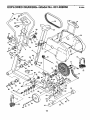
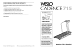
Note: =#" indicates a non-illustrated part. Specifications are subject to change without notice. See the back cover
of this manual for information about ordedng replacement parts.
14
:_
rl
r
EXPLODED DRAWING---_-ModelNo. 831.28_:_50
RllgSA
44
53
m
54
/
11
t
14
lO
72
72
16
57
29
1\
66
17
18
\
62
37
\
51
38
19
3
8
46
35
34
33
66
29
63
63
15
S£ARS
Mode[ No. 831.288250
The model number and serial number of your PROFORM" 770S
are listed on a decal attached to the frame. See the front cover of
this manual to find the location of the decal.
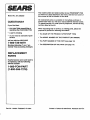
If you find that:
All replacement parts are available for immediate purchase or
special order when you visit your nearest SEARS Service Center.
To request service or to order parts by telephone, call the toll-fre(_
numbers listed at the left.
• you need help assembling or
operating the PROFORM 770S
When requesting help or service, or ordering pads, please be
prepared to provide the following information:
QUESTIONS?
• a part is missing
• The NAME OF THE PRODUCT (PROFORM = 770S)
• or you need to schedule repair
service
• The MODEL NUMBER OF THE PRODUCT (831.288250)
call our toll-free HELPLINE
• The PART NUMBER OF THE PART (see page 14)
1-800-736-6879
Monday-Saturday,
7 am--7 pm
Central Time (excluding holidays)
• The DESCRIPTION
OF THE PART (see page 14)
REPLACEMENT
PARTS
If parts become worn and need to
be replaced, call the following
toll-free number
1-800-FON-PART
(1-800-366-7278)
Part No. 134321 F03292AC R1196A
Printed in Taiwan © 1996 Sears. Roebuck and Co_