1
Metal FoBd-Up Utility Traiter
Moden No. 0220
Sears
_;,,_,;_:_,
Item No. 123.24201
User's Manual and Maintenance
'_
_de
Q ue st l Ons?:_.,_,,..
Please
call 1-800_22:38_5:,_
DO NOT RETUR
THE STGRE
Call 8:00 a m to 6:00 p m Monday throt]_i_Jay
Store
this manual
in the glove
\; _,;
compartment
_2_,
(C_ntrai Standard Time)
of you_ tow vehicle
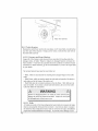
Z/y_Warning:
instructions
lTor safe opeiation
of this trailer, be sure to read all
and warnings
T:Failure to follow instructions
and
warnings
result
could
Instruction No 1028211
in ptope_ty
damage,
serious
injmy
and death
5/14/2007
Register
your
product
at www.lifetime.com.
www.lifetime.com
Craftsman
Metal
Fold-Up
Utility
Trailer'
Model No, 0220
Sears Item Nor 123o24201
WARNING
This User's Manual contains safety information and instructions for your trailer. You
must read this manual before loading or towing your trailer, You must follow all
safety precautions and instructions
For' parts and se_vice, call our customer service line at: 1-800-422-3865
NHTSA
Notification
Statement:
If you believe that your vehicle has a defect that could cause a c_ash or could cause
injury or death, you should immediately intbrm the National Highway balTic Safety
Administration (NHTSA) in addition to notifying Lifetime Products
IfNHTSA receives similar complaints, it may open an investigation, and if it finds
that a safety defect exists in a group of vehicles, it may oIder a recall and remedy
campaign, However; NHTSA cannot become involved in individual problems
between you, Sears, or Lifetime Products.
To contact NHTSA, you may either call the Vehicle Safety lqotIine toll-flee at 1888-327-4236 (TTY: 1-800-424-9153), go to http:!iwww.safeca[ gov; or write to:
Administt-ator; NHTSA, 400 Seventh Street, SW, Washington, DC 20590. You can
also obtain other information about motor vehicle satiety flora http:/!www.safecar gov
Calt 1-800-422-3865 to reach our Customer Service line,
..........................
, ,,.,; ........
..............
;,
3
Table of Cbntents ............................................
SECTION
SECTION
1: SAFETY INFORMATION
2: TIL, klLER PARTS & HARDWARE
7
1I
SECTION
SECTION
SECTION
3: FIRST-TIME
SET, UP REQUIREMENTS
4: TRAILER
SETUP
5: COUPLING
TO TIlE TOW VEH ICLE
12
17
19
5,1
5.2
Using an Adequate
Tow Vehicle and Hitch
Coupling
and Uncoupling
the Trailer
E2,1 Trailer with Ball-Hitch
Coupler
5,2 1 1 Bejbre coupling the trailer to the tow vehicle
5 2 1 2 Prepare the coupler and hitch
5 2 1, 3 Coupling the trailer to the tow vehicle
19
19
19
20
20
20
.5 2 t 4 R(qging the _q['ety chain_
5 2 t 5 Comwcting
the electrical cables
52 t 6 Uncoupling the Trailer'
;ECTION
6: TIRE & SAFETY INFORMATION
6ol Determining
6,1.1 Trailers
21
22
2.3
24
Correct
Load Limit - Trailer
10,000 Poltttd_" GVWR or Less
6°2 Determining
Cor'rect Load Limit - Tow Vehicle
6.3 Glossary of Tire Termiuology
6°4 Tire Safety - Everything Rides on tt
6.4,1 Safety fir_t-Basie
tire maintenance
6,4,2 Finding your vehicle'_ recommended
tire pressure
6,,4o3 Understanding
tire pressure and load limits
6.4,4 Checking tire pressure
6o4_5 Steps for maintaining
proper tire pressure
6.4,6 Tiresize
6°4, 7 Tire tread
24
24
and load limits
6.4,8 Tire balance and wheel aligttment
6,4.9 17re repair
6,4, I0 Tire Fundamentals
30
30
,30
6"4
6 4
6 4
6.4.11
6 4
64
30
32
32
3,3
33
.33
10 1
102
10.3
Tire
11 t
11 2
hformation
on Pas-senger Vehicle ?Tres
UTQGS lrfbtmation
Additional
Information on Light 7)'uck Tires
SafeO' Tips
Preventing Tire Damage
Tire SafeO Check/£st
6.5 Changing
a Flat Tire
6.6 Checking the Tire Pressure
_ECTION
7: LOADING
THE TRAILER
7.1. CHECKING
THE TONGUE
WEIGHT
ZLt
7.2
Checking
Tongue
Weight -_- Ushtg a lever and bathroom
Securing the Cargo
ZZt Loading Cargo
7.2.1.1 Preparin_ the Trailer for Loadin_
y.
24
24
27
28
28
28
29
r29
29
30
33
35
36
38
scale
,38
38
,38
39i
7 2 1, 2 l.oading the Trailer
SECTION
8: CHECK TRAILER
BEI ORE & DURING
SECTION
9: BREAKING
IN A NEW TRAILER
SECTION
10: MAINTENANCE
10.1 Inspection,
Service & Maintenance
Summary
10,2 Inspection
and Service Instructions
IO.,Z1 Axle Bolts', I*¥ame, Su,_pension,
& Structure
10.2.2 Trailer Structure
I0,2 2 t Fa_tener:s and Flame Members
t0 2 2 2 Welds
1&2.3 Trailer Connection
to Tow Vehicle
10 2 3 t Coupler
lOoZ4
llLZ5
lO.Z6
lgL2o 7
and Balt
t,anding Leg or Jack
Lightv attd Signals"
ITres
Wheel Ritns
lO.Z8 tVheels, Bearing_ attd I.ug Nttt_
tO .2 8 t Um'ealed Bearing_ (tfub_)
10.2,,9 i_ug Nttts (Bolls')
I O.Z t O Sus_pen._ion
SECTION
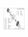
11 : EXPLODED
TRAILER
VIEWS
SECTION
12: \VARRANTY
INFORMAlION
TOWING
Charts
39i
41
43]
44i
44!
4si
45i
46
46
46
47
_7
47
47
4s
48
4a
48
49
49
5O
56
This Page Intentionally
6
[,eft Blank
SECTION
1: SAFETY
INFORMATION
SAFETY
ALERT
SYMBOLS
AND
SIGNAL
WORDS
manual is denoted by the safety
The safety information in this
t
alert symbol:
i/_k
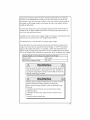
The level of risk is indicated by the following signal words:
SIGNAL
WORDS
Warning
Hazards or unsafe practices
which COULD result in severe
personal injury or death if the
warning is ignored.
Caution
Hazards or unsafe practices
which could result in minor or
moderate injury if the warning is
ignored,
Ifa label becomes unreadable, you can [e-order them fi"om Custome_ Service:
1-800-422-3865
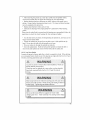
Warning
Labels
& Locations
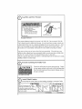
O
Lug Nuts
and
Tire Pressure
:b_'r_"a:=_=
control
Before towing,
you must
1 Tire pressure
and tread
2 Tires and wheels for damage
3
Lug nuts
©
2002
CHECK;
for tightness
For new and remounted
retighfen
tug nuts at
10,
* :_7"_
wheels,
the first
25 and 50 m_les o_ driving
NAT_1
ReL0rder # 1025343
The proper tighmess (torque) for lug nuts is 95-120 ft ilb. Do not exceed 120 R/lb
Use a torque wrench to tighten the lug nuts. If you do not have a torque wrench, use
a Iug wrench (from your tow vehicle) and tighten the nuts as much as you can Then
have a service garage or' trailer dealer tighten the lug nuts to the proper torque See
the section on Tire and Safety Information fo_ more details concerning tire safety
Lug nuts are also prone to loosen after first being assembled When driving a new
trailer (or after wheels have been remounted), check to make sure they are tight after
the fi_st 10, 25 and 50 mites of driving and before each _ow thereafter
Failure to perfbrm this check can result in a wheel parting from tire trailer and a crash,
leading to death or serious injury
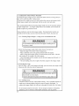
Securely
Latching
the Trailer
CAUTION
Gate
Ensure the trailer gates are secure during towing Failure
to insert gates securely could result in the toad separating
from the trailer causing serious property damage, personal injury and death.
Re-order # I012296
i
ii
i
ii
n ii ii
,
i, nlllnl
iii
u
,hi
, ,q,,,ql .....................
i,,-,
Assist keep
Wheel
Caution
Always
tire Assist
Wheel up when loading, unloadin or towing the Trailer,
CAUTION
AI ....
WAYS load and tow the Trailer
pcrmarmnl damaze to _,geAssis_ Wheel
ZE
_,=_)_'_['_
_
_\
_.,
| .....
]
_'
CAUnONZ1
1_1
_.
Pari #i 024838
Part #1025229
Part # 1025229
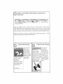
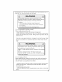
Coupler,
Connections Load
Weight
and
Distribution
and
[_
Electrical
:PI; '_WARNING;:
:
:l
R e-order # 1024843
Loads can suddenly move or topple, which can result in death ol selious injuly
Overloaded uaiters and imprope_ tongue weight can result in loss of control of the
trailer Ensme the trailer is coupled correctly and the chains are crossed over each othm:
Ensure the toad is tied securely and doesn't exceed the Gross Vehicle Weight (GVW)
Ensure the elecuical connections are tightly fitted and functioning properly
check b_eak lights and turn signals before each tow
i
Pinch
i ii
u,l,l..ull,,t,l,t,l,,,,,i,,lll,,u,
Point
Warning
Ahvays use the
Hand Crank
when tolding
and deploying
Trailer Ensure
Watch for pinch
points while
folding or
deploying trailer
as serious iniury
could occur.
Ahvays
others keep a safe
distance to avoid
any potential
pinch points
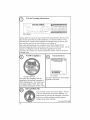
®
Folded
Trailer
"t'[OU Carl
NEVER tow
]railer while in
Warning
stoie
the rraile_ in
fblded position,
but do NOr tow
folded position
the Trailer while
Failme to heed this it's tbIded The
warning may void
1-railel may tip
warrm_ and could ove_ Jesulting in
result in properly
property damage,
damage, serious
serious injmy or
death
injury or' death.
Part fl1025112
_a_ #1024837
©
Tire and
Loading
Information
No re_orders
Always check tire pressure to ensure optimum Iife and perfomlance from your tires
-Filetires tbat came with your trailer should have a tire pressure of 80 psi Sears,
Roebuck and Co, cannot be held responsible ['or damages caused by uneven tread
wear and blow outs from an under-inflated or overqnflated tire
]-he Trailer and load should never' exceed tile Gross Veh icle Weight (G VW).
Whenever loading tile traileh always cheek to see if you're within this timit See the
section on Loading the Trailer for infomlation regarding how to check
This sdeker also displays your Vehicle Identification Numbel (VtN) in the bottom,
left-hand comer
NATM
Compliance
Patent
Advisory
HVETI_I_om_O_)UCTS
PRODUCTIDC'3_I..I_
_k 0201
J_
g?;):2.',::;_
',d;;?2',:',_,:_.
......
I_tgB3
o_
Re-order
Your trailer is in compliance with the
guidelines of the National Association of
Traiter Manufacturers Your trai_er has its
own unique number Note: This is not
,our Vehicle Identification Number (VIN)
O
t0
_
*'If' _
No re_orders
#1014245
i
)020t
i
i
Ball and Hitch
i
i
i
u u
i
u
This sticker' displays the various patents
applicable to the _railer:
ii HHm
,
U
,m
I,
Size
Your' new trailer comes with a 2qnch coupler The ball
on the tow vehicle must be 2 inches in diameter: An
incorrect ball size can cause the sepmation of the trailer
from the tow vehicle resulting in possible property
damage, serious injury and death,
Re-order #1013499
SECTION
2: TRAILER
PARTS
&
HARD WARE
Befbre beginning assembIy, inventory atl parE_ using the Parts List and the Hardwine Identifier (below)
lfall proIs are not present, do NOr assemble the trailer
Call 1-800-422-.3865.
ID
AA
AB
AC
AD
AE
Description
Gate/Ramp
Hand Crar_k
2" x 4" Distance Indicator (Do Not Discard)
1 ocktng Pin w/I anyard (Connected)
Cot.er Key (Connected)
_ll
i
Qty
2
l
[
[
[
-_
[]
[]
[]
[]
[]
i
HARDWARE
IDENTIFIER
(*Not to Scale)
*AA
*AD
•
I
* AB
Do Not Discard
I
I3/16" Lug Wrench or Iire Iron (t:or changing Tires and periodic tightening of Lug
_ts]
......... J
i1
SECTION
FIRS3 TIME
3:
SET-UP REQUIREMENTS
Lug Nuts: Tightening
Sequence,
3brque Requirements
- Before unfbldhag your lrailer, remove the plastic Zip Tie holding the Locking Pin
to the Tongue of the trailer
Do not cut the Lanyard (_rT.
...............
-_
!,_>"....
Locking Pin
Lanyard
Lug nuts are prone to loosen al_er initial installation possibly causing
the wheel to separate from the trailer leading to property damage, death
or serious h!jury
• Check lug nuts fk_rtightness on a new trailer or when wheel(s) have
been remounted after the tirst t 0, 25 and 50 miles o[ d_lying and
after any intpact
• Lug nuts lot the tires must be tightened by the user belb_e each use
• Sears cannot be held responsible for damages caused by loosened
lug nuts
• Before towing the Tlailer; you must ensme
the lug nuts are tightened
to the ploper
torque
• "[lie torque requirements
tbr the Lug Nuts are 95 - t20 It,/Ib Do not exceed 120
ft ilb of torque
Tighten the Lug Nuts in the sequence below befm*e you leave the
dealer
Tighten tug nuts
in the fo|lowing
order:
Verify the proper PSI for your tile
• Tire pressure for the t2" _im & tire should be at 80 psi
Foltow posted speed limits but do not exceed 65 mph
_efore loading Trailer, Trailer must be propm ly connected to
the Tow Vehicle to stabilize the Trailer Failure to f611ow this
warning could result in propeily damage, personal injury and
death.
12
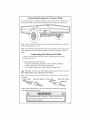
Connecting,
3¥mporary
License
Plate
t f your state requires a tempormT license on your traile< secure the license to the
license plate hotdet located on the left blinker before towing youi tlailer home
"1 /
Note: Before leaving the dealel, ensure you have the Manufactulets
Origin (Title) signed ovet to you
Certificate of
Note: FoE'alI inquiries regarding trailer' title and registration, please contact your
toca[ Department of Motor Vehicles (DMV) ot youi local coonly tax assessor's
OffiCe
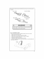
Connecting
the Electrical
Cables
Connect the nailer lights to the tow vehicle's electsreal system using the
electrical connectors
• Check oil lights for proper' operation
I Clearance and Running Lights (Tutn on tow vehicle headNghts)
2 B_ake Lights (Step on tow vehicle brake pedal)
3 -rurn Signals (Operate tow vehicle directional signal lever')
/_
Warning: Fo ensme your' trailer lights function pioperty, firinly insert the
Plug (Yr"iiler) into the Receptor (Tow Vehicle)
Note.: [f your colmeclor does not look like the one piclu#ed
an adapte_:
FIom Trailel
From Tow Vehicle From Traiier
) OUneed to purcha_e
Flora Tow Vehicle
Note: Please read Sections 4 and 5 for additional information on deploying,
coupling and towing your trailer
13
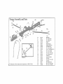
SF-E- CTtON4:
TF 43LER
Hardware
Used
_Not actual size
SETUP
.,______,AB
Ji
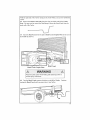
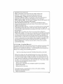
Before towing your nailer home you must fi_st unfold it and assemble the fiont and
rear panels
4oi Before unfblding your Trailer. remove the plastic Zip Tie holding the Locking
Pin to the Tongue of the Yrailer Do not cut the Lanyard
4.2 tilt the front of the Tmiter upward and lower the Assist Wheel to the ground
LocMng Pin
Latlyard
Assist Wheel
Tongue
4.3 Pull forward on t:he Trailel until the side of the Trailer rests on the Assist Whee!
14
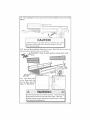
WiththerightsideoftheTrailerresting
ontheAssistWheel,
youcannowunfoldthe
IYaiter;
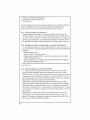
4.4 Remove
theHandCrank(AB)floratheclipsjustinsidewalloftheTrailer.
Note:Youmayneedtoremove the Gate/Ramp to access the Hand Crank from the
insde wall of'the Trailer:.
4.5 Insert the Hand Crank
the Trailer (as shown).
into the jack's Hand Crank
Coupler
Plate at the rear of
Hand
Watch for pinch points while folding and deploying trailer as
serious injury could occur,
4.6 Turn the Hand Crank counter-clockwise
to unfold the Trailer
Continue
turning the Hand Cr-'mk until you cannot turn it any further
15
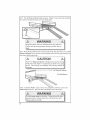
4.7 Remove
theCotterKey(AE)floratheLockingPin
Pin h_to the Bed Pin Retainer
(AD) and inselt the Locking
a_d through the Tongue
Note: lf the hole_ in the Bed Pin l?etainez and Tongue do trot align, you mttst fidl3_
infold the trailer:
t ""_
4,8
16
O
O /
Secure the Locking Pin (AD) in place with the Cotter Key (AE)
4°9 After unfolding
Wheel
the Ttailer,
[ift up on the fl'ont of the Trailer
and tett act the Assist
CAUTION
,4L_c\"A_ .q load
and
tow thc "['falTer
white
1.11t_Assist
\Vl'_ee[
is up
Failure
to heed this _arning could result in l_ennanent damage to tim Assist
[Wheel and void v, arranty.
4.10
Insert the Front and Rear Gates (AA) in place
can insmt each in either the fi'ont ot teat' position
WARNING:
Watch
for pinch
points
]_
1_
I_
Both Gates are the same; you
as serious
injury
could
4,11
Press down firmly
on the Gates until they
tock into place under the
Lips of the Side Panels
Do NOT use the Gates for tie-down locations All articles being
towed must be tied to the side walls of the Trailer, Gates can
dislodge causing property damage and possible ir_jm3,'or death to
other motolists and pedestrians
1.7
4,t2 Use the Front and Rear Gates as tamps Simply remove each Gate and place
tire ends into the channel at the lear of the Trailel Bed
4,t3 When driving vehicles such as ATVs up the ramps, fiEst place the 2" x' 4" x 63"
Distance indlcatm in the grooves of the side panels where the hont gate should go to
help you avoid dt iving too far
CAUTION
The 2" x 4" Distance Indicator' will not pt event you fi=omdriving
offthe fiont of the Ftailer It is used to let you know you're goinz
too fb.t Drive sIowly and cautiously when driving vehicles up
2" x 4" x 63" Distance
'
18
Indicator
Do Not Discard
SECTION 5: COUPLING
THE TOW VEHICLE
ATTACHING
THE TRAILER
TO TOW
TO
VEHICLE
You must follow all of the safety precautions and instructions in this manual to
ensure safety of persons, cargo, and satisfactorT lifi_ of the trailer°
A
5.1 Warning:
Using an Adequate
Tow Vehicle and Hitch _,_
lfthe vehicle or hitch is not properly selected and matched to the Gross Vehicle
Weight Rating (GVWR) of your trailer, you can cause an accident that couId lead to
death or serious injury If'you already have a tow vehicle, know your' vehicle tow
rating and make certain the trailer's rated capacity is less than or equal to the tow
vehicle's rated towing capacity tf you already have (or plan to buy) a tlailer; make
certain that the tow rating of the tow vehicle is equal to or greater than that of the
traite_
5.2 Warning:
Coupling and Uncoupling the Trailer
A secure coupling (or fhstening) of the trailer to the tow vehicle is essential. A loss
of coupling may result in death o_ serious injury -fheretbre, you must understand
and follow all of the instructions for coupling your trailer to your tow vehieIe.
The following parts axe involved in ensuring a secure coupling between the trailer
and tow vehicle:
Coupler: A device on the tongue of the tTailer that connects to the hitch on the
tow vehicle
Hitch: A device on the tow vehicle that supports the weight of the trailer tongue
and pulls the trailer. The coupler attaches to the hitch.,
Safety chains: lfthe coupler connection comes loose, the safety chains can keep
the traiIer attached to tbe tow vehicle. With properly rigged safety chains, it is
possible to keep the tongue of the traiIer from digging into the road pavement,
even if' the coupIer-to-hitch connection comes apart
Trailer lighting (and braking) connector: A device that connects electrical
power from the tow vehicle to the trailer; Electricity is used to turn on brake
lights, running lights, and turn signals as r'equired
5.2.1 Trailer with BalI-Hi|ch Coupler
A ball hitch coupler connects to a ball that is located on or' under the rear bumper
of the tow vehicle. This system of coupling a trailer to a tow vehicle is sometimes
referred to as "bumper pull."
_
Warning: We have utilized a 2-inch Ball Hitch coupler that is suitable for the
size and weight of the trailer You must provide a hitch and 2-inch ball fbr
your tow vehicle. 3vtj.e_re
t he_joad_ratjon_of the hit__chand ball is e_u.a!tg__eater
19
thanthatofyourtrailerAlso,thebalisizemustbethesame
asthecoupler
size if
thehitchbahistoosmaII,toolarge,isunderrated,
islooseor'isworn,thet_afler
can
comeloosefromthetowvehicle,
andmaycause
death
orserious
inimy.
IHE TOWVEHICLE,HITCHANDBALLMUSTHAVEARATEDTOWING
CAPACITY
EQUAl,.
TOORGREATER
THANTHETRAILER
GROSS
VEHICLE
WEIGHTRAIING(GVWR).
IT IS ESSENTIAL THAT THE HITCH BALL BE OF THE SAME SIZE AS THE
COUPLER (2 INCHES)
The ball size and load rating (capacity) are marked on the ball; hitch capacib, is
marked on the hitch
5,.2.,1,1 Before coupling tile trailer to tile tow vehicle
, Ensure the size and rating of hitch bail match the 2dnch coupler on your trailer
flitch balls and couplers are marked with their size and rating
• Wipe the hitch ball clean, inspect it visually and feet for flat spots, cracks and
pits
• Rock the batl to make sure it is tight to the hitch, and visuaIly check that the
hitch bali nut is solid against the lock washer and hitch flame
• Wipe the inside and outside of the coupler clean and inspect it visualiy fbr cracks
and deformations; feel the inside of the coupler for worn spots and pits,
• Be sure the coupler' is tight to the tongue of the trailer All coupler fasteners
must be visibly solid against the tlailer frame,
• Raise the bottom surface of the coupler above the top of the hitch ball Use
wood or concrete blocks to support the trailer tongue
5.2.1,2
Preparing
the coupler
and hitch
• Lubricate the hitch ball and the inside of the coupler with a thin layer of
automotive bearing grease
• Open the coupler locking mechanism. Ball couplers have a ]ocking mechanism
with an intemat moving piece and an outside handle
tn the open position, the coupler is able to drop fully onto the hitch ball
See "Uncoupling tire Frailer" for details on placing the coupler in the "open"
position,
- Slowly back up the tow vehicle so that the hitch ball is near or aligned under the
coupler
5.L1.3 Coupling the trailer to tile tow vehicle
Lift the coupler and place it over the bali.
• Lower the trailer until the coupler fully engages the hitch ball. If the coupter
does not line up with the hitch bail, adjust the position of the tow vehicle.
. Engage the coupler locking mechanism In the engaged position, the locking
mechanism securely holds the coupler to the hitch ball,
2O
• Ensure the couple_ is all the way otl the hitch ball and the locking mechanism is
engaged,
• Lower the trailer so that its entire tongue weight is held by the hitch Push the
safety latch downward to a horizontal position to lock it in place
• Pull up on the couplet to ensme it is securely fastened t.o the tow vehicle
If' the coupler cannot be seem ed to the hitch ball, do not tow the trailer.
Refer to Section 10o2.3 I0r information on coupling your trailer,
g-.
r,
;L ........
lose 30W Motor Oil to lubricate the ball mad inside of coupler
Always cheek ball and couplel betble each tow for damaged ot
worn edges Damaged balIs and couplers shoutd be replaced
immediately Failure to follow this warning could result in
propelty damage, personal injury and death
5,2,,1o4 Rigging the safety chains
• Visually inspect the safety chains and hooks *0r wear' ol damage Replace worn
or damaged sa|Ety chains and hooks before towing
• Rig file salety chains so that they:
1 cross underneath the coupler';
2 loop around a frame member of the tow vehicle or to holes provided in the
hitch system (but, do not attach them to an interchangeable part of the hitch
assembly); and
3 have enough slack to permit tight turns, but not be close to the toad sm face,
so if the trailer uncouples, the safb_b, chains can hold the tongue up above the
road
2t
Improper
riggingofthesafety
chainscanresultinlossofcontrol
ofthetrailerandthetroyvehicle,leading
todeath
orserious {i
injury,if thetraileruncouples
fromthetowvehicle
!
• Fasten
chains
toframeoftowvehicIeDonotfasten
chains
6
to any part of the hitch unless the hkch has holes or loops
specifically for that purpose
• Cross chains underneath hitch and coupler with enough slack
to permit turning, and to hold tongue up, if the trailer' comes
loose
1
5.2.1.5 Connecting the electrical cables
Connect the t:railer lights to the tow vehicle's electrical system using the electrical
connectors
• Check all lights fbr propel operation
1 Clearance and Running Lights (Turn on tow vehicle headlights)
2 Brake Lights (Step on troy vehicle brake pedal)
3 Turn Signals (Operate tow vehicle directional signal levm)
//_
Warning:
1"oensure your trailer lights function properly, fim_Iy insert the
Plug (TraileO into the Receptor' (row Vehicle)
Follow posted speed limits but do not exceed 65 mph
22
Note: t/),o_tr connectol
on udapte¢_
does" not look like the one pictm ed you need to put chage
From
From Trailer
From Trailer
Tow
Vehicle
From Tow Vehicle
5.2,1,6 Uncoupling the Trailer
Follow these steps to uncouple your ball hitch trailer fi'om the tow vehicle:
I, Remove the Ioad flora the trailer_
2 Block traiter tires to prevent the uaiier f_om rolling
3 Place wood or concrete blocks under the coupler for' support
4, Disconnect the electrical connector:
5 Disconnect the safi_ty chains flora the tow vehicle
6, Unlock the couple_ and pull the safety latch upward to a vertical position and
lift the trailer off the batI
Unlock
.................
.
::..........
:v:.,
¸ ..._
...... _,
,:
:..:
H:.
_,. ,:
23
SECTION
TiRE &SNFETY
''
INFORMATION
CHECKING
& CHANGING
TIRES
6ol Determining Correct Load Limit -Trailer
6.LI Trailers 10,000 Porrnds GVWR or Less
1 Locate the statement, "Jhe weight of cargo should never exceed XXX kg or
XXX Ib ," on your' vehicle's placard..
2 This figure equals the available amount of calgo and luggage load capacit5 _,
3 Determine the combined weight of luggage and cargo being loaded on the
vehMe Ihat weight may not safely exceed the availabIe cargo and luggage load
capacity'.
The trailer's placard refers to the Tire Intbrmation Placard attached adjacent to o1"
near the traitm's VIN (Certification) tabel at the left front of the trailer
6_2 Determining Correct Load Limit- Tow Vehicle
t.. Locate the statement, "The combined weight of occupants and cargo should
never exceed XXX lb ," on your' vehicle's placard
2. Determine the combined weight of the driver' and passengers who wiIl be riding
in your vehicle
3. Subtract the combined weight of the driver and passengers from XXX kilograms
or XXX pounds..
4. the resulting figure equals the avaiiable amount of cargo and luggage capacity
t:or example, if the "XXX" amount equals 1400 Ib mid there wilt be five t50 lb
passengers in your vehicle, the amount of available cargo and luggage capacity is
650 Ib (I400-750 (5 x t50) = 650 Ib)
5. Determine the combined weight of luggage and cargo being loaded on the
vehicle That weight may not safely exceed the available cargo and luggage capacity
calculated in Step il 4.
6. If your vehicle wiIl be towing a trailer, load from your trailer will be tmnsfened
to your vehicle Consult the tow vehicle's manual to determine how this weight
transfer' reduces the available cargo and luggage capacity of'your vehicle.
6.3 Glossary of l-ire Terminology
Accessory weight: The combined weight (in excess of those standard items which
may be replaced) of automatic transmission, power steering, power brakes, power"
windows, power seats, radio and heater, to the extent that these items are available
as fhctory-installed equipment (whether insmlIed or not).
Bead: The part of the tire that is made of steel wires, wrapped or' reinforced by ply
cords and that is shaped to fit the tim
Bead separation:
This is the breakdown of the bond between components in the
bead.,
Bias ply tire: A pneumatic tire in which the ply cords that extend to the beads are
laid at alternate angles substantially less than 90 degrees to the center' line of the
tread,
24
Carcass;Thetirestructure,
except
treadandsidewalt
rubber
which,wheninflated,
bears
theload
Chunking:Thebreaking
awayofpieces
ofthetreadorsidewall
Cold inllation pressure: The pressure in the tire before you drive
Cord: The strands fbrming the plies in the tire
Cord separation:
"fhe parting of cords from adjacent rubber' compounds
CracMng: Any parting within the tread, sidewall, or inner liner of the tire
extending to cord material.
CT: A pneumatic the with an inverted flange tire and rim system in which the 1im
is designed with rim flanges pointed radially inward and the tire is designed to fit
on the underside of the rim in a manner that encloses the rim flanges inside the air
cavity' of the tire
Curb weight: The weight of: a motor vehMe with standard equipment including
the maximum capacity of'fuel, oil, and coolant, and, itso equipped, air conditioning
and additional weight optional engine
Extra load tire: A tire designed to operate at higher loads and at highel inflation
pressures than the corresponding standard tire.
{Sroove: The space between two adjacent tread ribs
Inner liner: The layer(s) fbrming the inside sur[hce of a tubeless tire that contains
the inflating medium within the tire
Inner-liner separation:
The parting ofthe inner liner from cord material in the
carcass
Intended outboard sidewall The sidewall that contains a white-wall, bears white
lettering or bears manufacturer, brand and/or model nmne molding that is higher or
deeper' than the same molding on the other sidewall of the tire or the outward t_acing
sidewall of'an asymmetrical tire that has a par_.icular side that must always face
outward when mounted on a vehicle.
Light truel{ (LT) tire: A tire designated by its manufacturer as primarily intended
for use on lightweight tr_cks or multipurpose passenger vehicles
Load rating: The maximum load that a tire is rated to carry fi_r a given inflation
pressu[e
iVlaximnm load rating: The load rating R)ra tire at the maximum permissibIe
inflation pressure tbr that tire
Maxhnnm permissible iMlation p, essurc: 1-he maximum cold inflation pressure
to which a tire may be inflated
Maximum loaded vehiele weight: The stun of curb weight, accesso W weight,
vehicle capacity weight, and production options weighL
Measuring rim: The rim on which a tire is titled fbr physical dimension
requirements.
Non-pneumatic rim: A mechanical device which, when a non-pneumatic tim
assembly incorporates a wheel, supports the tire, and attaches, either integrally or
separably, to the wheel center member and upon which the tire is attached
Non-pneumatic spare tire assembly: A non-pneumatic tire assembly intended
for temporary use in place of one of' the pneumatic tires and _ims that are fitted to a
passenger car in compliance with the requirements of this standard
Non-pneumatic tire: A mechanical device which transmits, either directly or
through a wheel or wheel center member; the vertical load and tractive fbrces from
3.-8
................
, ,,,,,,
..........
,...........
, ..............................
tire roadway to the vehicfe, generates the tractive tbrces that provide the directional
contiol of the vehicle and does not le[y on the containment of any gas o_ fluid for
providing those functions
Non-pneumatic tire assembly: A non-pneumatic tire, alone or' in combination with
a wheel or wheel center member, which can be mounted on a vehicle
Normal occupant weight: This means 68 kilograms (t50 lb,) times the number of
occupants specified in the second column of Table I of 49 CFR 57f. 110
Occupant distribution: The distribution of occupants in a vehicle as specified in
the third column of' Table I of 49 CFR 57I 1 t0
Open splice: Any parting at any junction of'tread, sidewall, or inner [liter that
extends to cord material
Outer diameter: rke overall diameter of: an inflated new tire
Overall width: The linear distance between the exteriors of the sidewalls of an
inflated ti_e, including elevations due to labeling, decorations, ol protective bands o_
ribs
Ply: A layer of rubber,coated parallel cords,
Ply separation:
A parting of rubber compound between adjacent plies,
Pneumatic tire: A mechanical device made of rubber, chemicals, fabric and
steel or other materials, that, when mounted on an automotive wheel, provides the
traction and contains the gas or fluid that sustains the load
Production options weight: ]-he combined weight of those installed regular
production options weighing over 2.3 kilograms (5 tb ) in excess of those standald
items which they replace, not previously considered in curb weight or accessory
weight, including heavy duly brakes, ride levelers, roof rack, heavy duty battery,
and special trim
Radial ply tire: A pneumatic tire in which the ply cords that extend to the beads
are laid at substantially 90 degrees to the center' line of the tread
Recommended inflation pl cssure: This is the inflation pressure plovided by the
vehicle rnanuthcmrer on the rite lnf0maation label and on the Cm tification / VIN
tag
Reinforced tire: A tire designed to operate at higher loads and at higher inflation
pressures than the corresponding standard tire
Rim: A metal suppor* for a tire or a tire and tube assembly upon which the tire
beads are seated
Rim diauieter: This means the nominal diameter' of the bead seat
Rim size designation:
1his means the rim diameter and width,
Rim type designation: This means the industry of manufacturer's designation for
a rim by style or code
Rim width: This metals the nominal distance between lira flanges
Section width: The linear' distance between the exteriors of the sidewalls of an
inflated tire, excluding elevations due to labeling, decolation, or p_otective bands
Sidewall: That portion of a tire between the tread and bead,
Sidewall separation:
The parting of the rubber' compound from the cord material
in the sidewall,,
Special Trailer (ST) tire: The "ST" is an indication the tire is for trailer use only,
Test rim: lhe rim on which a tire is fitted for testing, and may be any rim tisted as
26
appropriate for use with that tire
Tread: Fhat portion of'a tire that comes into contact with the road.
Tread rib: A tread section running circumferentiaiiy around a tire,
Tread separation:
Puliing away of the tread from tire tire carcass
Tread-wear indicators (TWl): rile projections within the principal grooves
designed to give a visual irrdication of the degrees of' wear of the t_ead
Vehicle capacity weight: The rated cargo and luggage load plus 68 kilograms (I50
Ib,,) times the vehicle's designated seating capacity
Vehicle maximum load on tile tire: The load on an individual tire that is
determined by distributing to each axle its share of the maximum loaded vehMe
weight and dividing by two
Vehicle normal load on the tire: Tile load on an individual tire that is determined
by distributing to each axle its share of the curb weight, accessory weight, and
normal occupant weight (distributed in accordance with Table l of CRF 49 571. l i0)
and dividing by Z
Weather side: ]*he surface area of tile rhn not covered by the inflated tire
Wheel center member: In the case of a non-pneumatic tire assembly incorporating
a wheel, a mechanical device which attaches, either integrally or' separably, to the
non-pneumatic rim and provides the connection between the non-pneumatic rim
and the vehicle; or; in the case of a non-pneumatic tire assembly not incorporating
a wheel, a mechanical device which attaches, either integrally or separably, to the
non-pneumatic tire and provides the connection between tire and the vehicle
Wheel-holding lixture: l-he fixture used to hold the wheel and tire assembly
securely during testing
6_4 Tire Safety - Everything Rides on It
The National Traffic Safety Administration t%_HTSA) has published a brochure (DOT
HS 809 361) that discusses all aspects of'Tire Safety, as required by CFR 575 6,,
This brochure is reproduced in part below It can be obtained and downloaded from
NHTSA, free of charge, from tile following web site:
http://www_,nhtsa dot govicars!ruleslTireSafety/ridesonibltires
jndex hm'_I
Studies of tire safety show that maintaining proper tire pressure, observing tire
and vehicle load limits (not carrying more weight in your' vehicte than your tires
or vehicle can safely handle), avoiding road hazards, and inspecting tires for cuts,
slashes, and other irregularities are tile most important things you can do to avoid
tire failure, such as tread separation or blowout and flat tires These actions, along
with other care and maintenance activities, can also:
• Improve vehicle handling
• Help protect you and others from avoidable breakdowns and accidents
- bnprove fueI economy
• Increase the life of your tiresThis booklet presents a comprehensive overview of'tire safety, including
information on tile following topics:
• Basic tire maintenance
27
• Uniform Tire Quality Grading System
• Fundamental characteristics of tires
• Tire safety tips
Use this intbrmation to make tire safety a regular part of your vehicle maintenance
routine Recognize that the time you spend is minimal compaied with the
inconvenience and safe_' consequences of a flat fire or' other tire fMfure
6.4,1 Safe_' first-Basic tire maintenance
Properly maintained tires improve the steering, stopping, traction, and loadcarl3,ing capability of you, vehicle Under-inflated tires and overloaded vehicles
are a major cause of tire failure Therefbre, as mentfoned above, to avoid fiat tires
and other types of tire failure, you should maintain proper tire pressure, observe
tire and vehicle load limits, avoid road hazards, and regularly inspect your tires
6.4.2 Finding your vehicle's recommended tire pressure and load limits
Zhe infbm_ation placards and vehicle certification labels contain infbrmation on
fires and toad Iimits, These labels indicate the vehicle manufacturer's irrlbrmation
including:
. Recommended
tire size
• Recommended tire inflation pressute
• Vehicle capacity weight (VCW-the maximum occupant and cargo weight a
vehicle is designed to carD')
• Front and rear' gross axle weight ratings (GAWR= the maximum weight the
axle systems are designed to car_y),
Both ptacards and certification labels are pe_manently attached to the trailer nezu'
the left front,
6°4.3 Understanding tire pressure and load limits
Tire inflation pressure is the level of air in dae tire that provides it with loadcanying capacity and affects the overall performance of the vehicle, The tire
inflation pressure is a number that indicates the amount of air pressure- measured
in pounds per square inch (psi)--a tire requires to be property inflaf;ed (You will
also find this number on the vehicle information placard expressed in kilopascals
(kPa), which is the metric measure used internationally,)
Manufacturers of passenger vehicles and light trucks determine this number
based on the vehicle's design load limit, that is, the greatest amount of weight a
vehicle can safely carry and the vehicle's tire size The proper the pressure for
your' vehicle is referred to as the "recommended cold inflation presstire " (As you
will read below, it is dit_cult to obtain the recommended tire pressure if your tires
are not cold,)
Because tires are designed to be used on more than one type of vehicle, tire
manufacturers list the 'maximun_ permissible inflation pressure" on the tire
sidewalI. This number is the greatest amount of air pressure that should ever be
put irathe tire under normal driving conditions,
28
6.4.4Checking
tire pressure
It isimportant
tocheckyourvehicle's
tirepressure
atleastonceamonthtot the
followingreasons:
• Most tires may naturally lose air over time..
• Tires can fose air' suddenly if you drive over a pothole or other object or' if you
strike the curb when parking.
• With radial tires, it is usually not possible to determine unde>inflation by visua[
inspection
For convenience, purchase a tire pressure gauge to keep in your vehicle. Gauges
can be purchased at tire dealerships, auto supply stores, and other retail outlets.
The reconm_ended tire inflation pressure that vehicle marmfhcturers provide
reflects the proper psi when a tire is cokt The term cold does not re[ate to the
outside temperature, Rather; a cold tire is one that has not been driven on for at
least three hours., When you drive, your' tiros get warmer; causing the aft' pressure
within them to increase Therefore, to get an accurate tire pressure reading, you
must measure tire pressure when the tires are cold or compensate for tire extra
pressure in warm tires
6°4.5 Steps for maintaining proper tire pressure
• Step 1: Locate the recommended tire pressure on the vehicle's tire information
placard, certification label, or in the owner's manual
• Step 2: Record the tire pressure of all tires
• Step 3: lfthe tire pressure is too high in any of the tires, slowly release air by
gently pressing on the tire valve stem with the edge of your tire gauge untiI you
get to the correct p_essure
• Step 4: if the tire pressure is too tow, note the difference between the measured
tire pressure and the correct tire pressure. These "missing" pounds of pressure are
what you will need to add.
- Step 5: At a service station, add the missing pounds ofair pressure to each tire
that is made>inflated
• Step 6: Check all the tires to make sure they have the same air pressure (except
in cases in which the fi'ont and rear tires are supposed to have different amounts o[
pressure).
If you have been driving your vehicle and think that a tr:ailer tile is under-inflated,
fitl it to fl_erecommended cold inflation pressure indicated on 3,our vehicle's tire
information placard or certification label While your tire may still be slightly
under-inflated due to tire extra pounds of pressure in the warm tire, it is safe.r
to drive with air' pressure that is slightly lower than the vehicle manufacturer's
recommended cold inflation pressure than to drive with a significantly underinflated tire Since this is a temporary fix, don't forget to recheck and adjust the
tire's pressme when you can obtain a cold reading
6A.6 Tire size
To maintain tire safety, purchase new tires that are the same size as the vehicle's
originat tires or another size recommended by the manufacturer.. Look at the
tire information placard, the owner's manual, or the sidewalI of the tire you are
29
replacing
tofindthisinformation
If youhaveanydoubtaboutthecorrect
sizeto
choose,
consult
withthetiredealer:
6°4°7Tiretread
The tire tread provides the gripping action and traction that prevent your' vehicle
fl-om slipping or sliding, especially when the road is wet or icy, In general, tires
are not safe and should be replaced when the tread is worn down to I116 of an
inch Tires have built-in tread-wear indicators that let you know when it is time
to replace your tires These indicators are raised sections spaced intermittently in
the bottom of the txead grooves. When they appear %yen" with the outside of the
tiead, it is time to replace your tires,, Another method for checking tread depth is
to place a penny in the tread with Lincoln's head upside down and lacing you., If'
you can see the top ofLincotn's head, you are ready tbr new tires
6.4.8 "Fire balance and wheel alignment
To avoid vibration or' shaking of the vehicle when a tire rotates, the tire must be
properly balanced This balance is achieved by positioning weights on the wheel
to counterbalance heavy' spots on the wheel-and-tire assembly A wheel alignment
adjusts the angles of the wheels so that they are positioned correctly relative
to the vehicle's frame This adjustment maximizes the life of yore tires 'fhese
adjustments require special equipment and should be performed by a qualified
technician,
6.4.9 Tire repair'
fire proper repair of a punctured tire requires a plug tbt the hole and a patch for
the area inside the tire that surrounds the puncture hole. Punctures through the
tread can be repaired if they are not too large, but punctures to the sidewall should
not be repaired. Tires must be removed from the rim to be properly inspected
before being plugged and patched
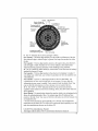
6.4.10 Tire Fundamentals
Federal law requires tire manufacturers to place standardized in tbrmation on tim
sidewall of aI1 tires This information identifies and describes the fundamental
characteristics of the tire and also provides a tire identification number tol safety
standatd certification and in case of a recall
6o4o10ol Information on Passenger Vehicle Tires
Please ret_r to the diagram on the next page.
3O
Radial
Ra|io of height to
width (aspect ratio)
Nominal width of
Rim diame|er
code
Load index &
eed sylabnt
tire in millimeters'
US. DOt" tire
Passen
ear tire
ide_lificalim_ numbel
Sever snow
conditions
'lire ply
Max,
¢_ntposition
permissabh
inlhttion
and malerinls
used
pr'_SSll l'e
P: The "P" indicates the rite is for passenger vehicles
Next number: This three-digit number' gives the width in millimeters of the tire
fi'om sidewall edge to sidewall edge. In general, the larger the number; the wider
the tire
Next number: This two-digit number, known as the aspect ratio, gives the tire's
ratio of height to width Numbers of 70 or lower indicate a short sidewall for
improved steering response and better overall handling on dry pavement
R: The "R" stands for radial. Radial ply construction of tires has been the industry
standard for the past 20 years..
Next number': This two-digit number is the wheel or rim diameter' in inches If
you change your wheel size, you will have to purchase new tires to match the new
wheel dimneter.
Next number: This two- or'three-digit number is the tile's load index. It is
a measurement of how much weight each tire can support You may find this
information in your owner's manual If not, contact a local tire dealer: Note: You
may not find this information on all tires because it is not |'equired by law
M+S: The "'M+S" or' "M/S" indicates that the tire has some mud and snow
capability Most radial tires have these markings; hence, they have some mud and
snow capability
Speed Rating: The speed rating denotes the speed at which a tire is designed to be
driven for extended periods of time The ratings range fiom 99 miles per hour
(mph) to I86 mph Note: Yon may not find d_is information on all tires because it is
not required by law.
* For tires with a maximum speed capability over 149 mph, tire manufacturers
sometimes use the letters ZR.. For those with a maximum speed capability over 186
mph, tfle manufacturers always use the letters ZR.
U.S, DOT Tire Identification Number
This begins with the letters "DOr" and indicates that the tire meets all
31
Ii_deral
standards,
Thenexttwonumbers
orletters
aretheplantcodewhereit was
manufactured,
andthe[astlburnumbers
represent
theweekandyear the tire was
built For example, the numbers 3 [ 97 means the 3 t st week of 1997. The other
numbers are marketing codes used at the manufacturer's discretion, This
information is used to contact consumers ifa tire defect requb'es a recall
Tire Ply Composition and Materials Used
The number of plies indicates the number of layers of rubber.coated fabric in the
tire. In general, the greater the number ofplies, tile more weight a tire can support
Tire manufacturers also must indicate the materials in tbe tire, which include steel,
nylon, polyester, and otbers.
Maximum Load Rating: This number indicates the maximmn load in kilograms
and pounds that can be carried by the tire
Maximum Permissible Inflation Pressure: lhis number is the greatest amount
of air pressure that should ever be put in the tire under normal driving conditions
6Ao10.2 UTQGS Information
Tread-wear Number: "Ftrismnnber indicates the tire's wear _ate The bigber the
tread-wear number is, the longer it should take for the tread to wear down For
example, a tire graded 400 should last twice as long as a tire graded 200
Traction Letter: _his tether indicates a tire's ability to stop on wet pavement A
bigber graded tire shoutd allow you to stop your car on wet roads in a shorter
distance than a tire with a tower grade Traction is graded from highest to lowest as
"AA","A", '_B",and _'C"
Temperature Letter: This letler indicates a tire's resistance to heat The
tempelamre grade is [br a th-e that is inflated property and not overloaded
Excessive speed, under inflation or excessive loading, either separately or in
combination, can cause beat build-up and possible tire failure. From highest to
lowest, a tire's resistance to heat rs graded as A , B , or
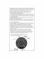
6o4.10,3. Additional Information on Light Truck Tires
Please refer to the following diagram:
M_lxlmumload
Load
& intlafion when
rllll
|ised
_ls II dultl
Sc_,'¢ t _ snow
I, igh_ truck tire
32
Tires for light trucks have other markings besides those lSund on the sidewalls of
passenger tires
LT: The %T" indicates the ti_e is fbr light tracks ol trailers
ST: An "ST" is an indication the the is for tlai[er use only
Max,, Load Dual kg (Ib) at kPa (psi) Cold: This inl:blmation indicates the
maximum load arid tire pressure when the tire is used as a dual, that is, when four
tires ale put on each rear axle (a total of six ol more tires on the vehicte)
Max,, Load Single kg (lb) at kPa (psi) Cold: This infbrmation indicates the
maximum load and the pressule when the tire is used as a single
Load Range: This infolmation identifies the tiEe's load-crowing capabilities and
its inflation limits
6.&tt Tire Safety Tips
64,I1.1 Pieventing l'ir'e Damage
• Slow down if you have to go ovm a pothole or other object in the road
• Do not run over curbs or othet fbreign objects in the roadway, and try. not to
strike the curb when parking
6°4°I 1,,2 Tire Sa I_:t3, Checklist
• Check tire pressure regularly (at least once a naonth), including the spate
• Inspect thes lot uneven were patterns on the tread, cracks, fbreign objects, or
other signs of wear of trauma
• Remove bits of glass and lbreign objects wedged in the tiead
. Make sine your tile valves have valve caps
• Check tile ptessm_e before going on a tong t_ip
• Do not ovmload your vehicle
6,5 Changing a Flat Tile
6_5ol If'possible, get the Trailer on level ground
65,2 Keep the Trailer coupled to the Fow Vehicle and engage the Fow Vehicle's
emergency brake
Never attempt to change the tile while trailer is in folded
position trailer can tip over
Failule to heed this warning could result in property damage, serious injm'y and death
33
6&3 Chock
theWheel
youalenotchanging
withbricksozwooden
blocks
......................
:_"__<!::
..........2_-I|
6.&4 Place a Tire Jack under the part of the axet near the fiat tire
65,5 Jack up the axle to lift the wheel a few inches offthe ground
....
....
Place a Tire Jack
here
6.5_6 Remove the t, ug Nuts and Wheel
:5 ;_,!_:;.' , Y /,,_ ":
:
:
'::":!i
/
: _;Y'_V
!:"........
', \:-bY ' /
6.5.7 Place Spare Fire on the axle and tighten Lug Nuts between 95 - 12!) It/Ib
Do not exceed 120 ff ilb
6°5°8 Tighten Lug Nuts in the following sequence:
34
65+9LowerTireJack
and remove fiona under Trailer
%
i;/
;:: ¸
Never crawl under a trailer on jacks The trailer could slip off
the,jack or the jack could fair resulting in smious injury m death
Lug nuts ate prone to [oosen aftra initiat installation, which can
lead to death or serious injury
Check tug nuts for tightness on a new trailm or+when wheel(s)
have been remounted after the first 10+25 and 50 miles of&lying and after any impact
Lug nuts for the tires must be tightened by the user befote each
use Sears cannot be held responsible for' damages caused by
loosened lug nuts
6,,6 Checking the Tire Plessure
Always check the tire pressure before each tow Use a pressure gauge to ensure
proper tire pressure Nm tires provided with your ]railer should be filled to 80 psi
1ire pressure must be checked when the tire is cold If the trotter has been towed
for at least one mile, allow at least three horns after a tow for tile tire to cool before
checking the pressure
To help ensure long tread life and your safety. Atways check
the pressure to ensure opthnum life and perfommnce from your
tires Tile tires that came with your trailer should have a tire
pressure of 80 psi Sears cannot be heId responsible for damages caused by uneven tread wear and blow outs I}oltl an underinflated or over-inflated tire"
35
SECTION
7: LOADHNG
TRAHLER
LOADING
THE
THE CARGO
Improper t+ailev loading causes many accidents and deaths
_OU llaLISt
consider:
To safely load a trailer,
Overall load weight;
Load weight distribution;
Prope) tongue weight; and
Securing the load pioperly
?o determine that you have loaded the tlailer within its rating, you must consider
the distribution of weight, as welf as the totat weight of the trailer and its contents
the trailer axles cmry most of the total weight of the trailer and its contents (Gross
Vehicle Weight, or "GVW") The remainde[ ot:the tolat weight is cmried by the tow
vehicle hitch For safi_ towing, it is essential that the trailer tongue and tow vehicle
hitch carry the prope_ amount ofthe loaded trailer weight, othelwise the traitel can
suddenly+ s_'ay _' 'ildty at towing speed Read the "]_ngue Weight" section below
The ioad distribution must be such that no component part of the trailer is Ioaded
beyond its rating This means that you must consider' the rating o1:the tires, wheels
and axles For tandem and triple axle trailers, you must make sure that the fiont*torear load distribution does not result in overloading any axle
rowing stability also depends on keeping the center' of gravity as low as possible
Load heavv items on the floor' and over the axIes When loading additional items, be
sure to maintain even side-to+side weight dist+ibution and proper tongue weight The
total weight of the trailer and its contents must never' exceed the total weight rating of
the tlailer (Gross Vehicle Weight Rating, or "GVWR')
An overloaded trailer can result in loss ofcontroi of the trailer,
leading to death or serious injury
Do not toad a trailer' so that the weight on any tire exceeds its
rating
Do not exceed the trailer Gross Vehicle Weight Rating (GVWR)
or an axle Gross Axle Weight Rating (GAWR)+
Tongue Weight
It is critical to have a portion of the trailer load carried by the tow vehicle That is,
the trailer tongue must exert a dowmvard force on the hitch lq_is is necessmy for two
reasons First, the propel amount of tongue weight is necessary for the tow vehicle
to be able to maintain control of'the tow vehicle/trailer system If, t:orexample, the
3.6
tongue
exertsanupward
pullontilehitch,instead
ofpushing
downonit (because
the trailet is overloaded behind its axle(s)), tile tear wheel of the tow vehicle can
lose traction ol grip m_dcause loss of control Also, even if there [s some weight on
the tongue, but not enough weight on the tongue, the trailer can suddenly become
unstable at high speeds
If, on the other hand, there is too much tongue weight, the front wheels of the troy
vehicle can be too lightly loaded and cause loss of' steering control and traction, as
welt, if the front wheels are &iving
In addition to tow vehicle control, tongue weight is necessary to insule that the tlailer
axle(s) do not exceed theil Gloss Axle Weight Rating (GAWR)
The table belmv has "tufes of thumb" fol pioper tongue weight
tn the table below, the second column notes tile rule of thumb percentage of total
weight of the trailer plus its cargo (Gross Vehicle Weight, or "GVW") that should
appear on the tongue of the trailer For example, a uailet with a ball hitch and a
loaded weight of 1.000 pounds, should have i0-15% of 1,000 pounds on the tongue
That is, the example tlailer would have no more than 100 to 150 pounds on its tongue.
a: ng6eWei htgs
Type of Hitch
Bail Hitch (ot Bumper Hitch1
LoaaeaTi:,,it W
r igii
Percentaae
10-15%
Never' go uudel the trailer unless it has been properly supported
with,jack stands that have been rated fbr the toad, Without be.ing properly suppor*ed, the trailer may fall suddenly which may
result in serious injury or death"
Improper tongue weight (toad distribution) can result in loss of
control of the trailer, leading to death or sel ious iniuty
Make certain that tongue weight is within the allowable range
Be sine to:
• Distribute the load front-to-rear to plovide propel tongue
weight (see chart);
• Distribute the load evenly, right and left, to avoid tire overload; and
• Keep the center of gravity low
....
_g-'3
37
7.1.CHECKINGTHETONGUE
WEIGHT
1"ocheck the tongue weight, the tow vehicle and trailer must be on level glound, as
they will be when the trailer is being towed
If you know the weight on your tow vehicle axles when you are not towing a tmilei,
trailer tongue weight can be determined with the use of a truck axle scale
The recommended method of checkina tonaue weight is to use an accessory called a
"tongue weight scale '_ Jf a tongue weight scale is not available, you can check the
tongue weight using a bathroom scale
Using a bathroom scale to check tongue weight: The loaded uailer must be on a
smooth and level surface, and you must block the trailer wheels, ftont and rear
7.1.1 Checking Tongue Weight--
Using a lever' and bathroom
scale
Before checking tongue weight, block trailer wheels, front and rear
• Raise the tongue of the trailer with the tongue jack
• Place a badlroom scale on the ground, directly below the couplet:
• Place a strong block support (such as a cement bIock) on the scale - note the
scale reading lot the weight of the block support.
• Lowm the tongue until the coupler rests on the block support and the jack is %
inch above the ground
• ]he scale reading, minus the weight of the block support is the tongue weight
7,,2 Securing tire Cargo
Si_ce the trailel "ride" can be bumpy and rough, you must secure your cargo so that
it does not shift while the trailer is being towed
7,2.1 Loading Cargo
Couple the traifer to the tow vehicle before loading This is essential because the
tongue can rise during loading, before the cmgo is properly distributed go
measure the tongue weight, 3,ou will have to uncouple the trailer after it is loaded
Do not transpo_t people in the trailer Do not transport containers of hazardous
substances, cans or' containers of flammable substances, such as gasoline,
38
kerosene,
paint,etc However,
fuel
it__be tank of an off-road vehicle, or a car or
motorcycle, etc may be carried on your open trailer
Do not transport flammable, explosive, poisonous or other
dangerous materials in your trailer Failure to heed this warning
could result in property damage, serious injury and death
Exceptions:
• Fuel in the tanks of vehicles that are being towed
, Fuel stored in proper containers used in trailer living quarters for cooking
• Fuet stored in the tank of an on-board generator
7,2ola P, eparing {:lieTrailer fnr Loading
Before loading cargo onto the trailer:
• inspect the deck of the trailer fb_ corrosion or damage; and
• inspect the hold down openings and/or "D'Mings, Hold down openings must
be sturdy with no visible clacks or kinks D-rings must be tight to the deck and
must not be bent
If the deck or any required hold-down is damaged, do not load the cargo Bring
the trailer to 3,our dealer- o_ a competent repair service bef01e using it to carry
cargo
Damaged or loose "D"-rings can break, allowing cargo to become
loose inside the traiJer Loose cargo can shift the center of gravity,
and result in loss of control of the trailm
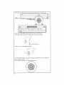
Inspect
cargo
Do not
Failure
serious
"D'-rings,
and test them tbr looseness before loading
use a damaged or loose "D'-riog to secure calgo
to head this walning could result in proper U damage:
injuw and deat!L
7_2,1.2 Loading the Trailer
Before loading the trailer; couple the trailer to the tow vehicJe and ensure the
deck is level Do not toad o_ unload the trailer when the deck is not level or'
when the ]¥ailer is not coupted to the tow vehicle
i Ensure the top of the ramp (or ramps) is secure to the trailer, and the bottom
is resting on firm ground Pockels may be provided to hold the ramp to the
frame of the trailer.
2 Load the cargo onto the trailer
3 Secure the cargo to the trailer using appropriate straps, chains and tensioning
devices
39
Sincetiletlailer"ride"canbebumpy
andrough,youmustsecure your
cargo so
that it does not shift while tile tlailer is being towed
4 Return tile ramp{s) to their stowed position(s), and secure them so that they will
not move during t_ansit
Before loading Trailer; T_ailer must be properly connected to the
Tow Vehicfe This stabilizes the Trailer Failure to follow this
winning could _esult in propelty damage, pmsonal injuly and
death,
: WARNnNG:
2
2;
:
:i,
Do NOT use the Gates for tie-down locations All articles being
towed must be tied to the side walls of tile Trailer Gates can
dislodge causing pmpmty damage and possible inim3, or death {o
other motorists and pedestt ians
4O
)
SECTION
8: CHECK
TRAILER
BEFORE
& DURING
TOWING
PRE-TOW
CHECKLIST
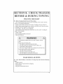
8.1 Before Towing, Double Cheek All These items:
• Tires, wheels and lug nuts (see the section "Breaking in New Trailer" and the
section "rite & Safety Intormation"
• Couplet secured and locked (see the section "Coupling to tlre row Vehicle _')
• Safety chains properly rigged to tow vehicle, not to hitch or ball (see the section
"Coupling to the Fow Vehicle" of this manual)
• rest of lights: rail, Stop, him and Backup
• Caigo ploperly loaded_ balanced and tied down (see the section "Loading the
Trailer" of tiffs manual)
• Tongue weight
• Doors and gates latched and secured
. Flaies and reflectors
An improperly coupled trailer can result in death or set'ions
injmT
I3o not move the trailer' until:
_rhe coupler is secured and locked to hitch;
the safety chains are secured to the tow vehicle; and
. Assist Wheel is fully retracted
• You secure Tongue to Bed usii_g Locking Pin and Cotter Key
Do not tow the trailer' on the road until:
- ri_es and wheels are checked;
• The load is secured to the trailer; and
• The trailer' lights are connected and checked
MAKE
REGULAR
STOPS
8.2 After Each 50 Miles, or One Hour of Towing, Stop and Cheek the Following
Items:
• Coupler' secured
• Safety chains are fastened and not dragging
• Cargo secured
• Cargo door latched and seculed
41
Sinceroads
canbebumpy
andtough,lugnulscanloosen
over
timeandevenseparate
fTomthewheelandpossibly
causing
the
separation
ofthewheelfl'omthetrailer thelugnutsmustbe
tightened
bytheuserbefore
eachuse
Thetiresmustbemaintained
attheproperthepiessure
befbre
eachuseSears
caimot
beheldresponsible
Ibtdamages
caused
byloosened
lugnuts,
o_uneven
treadwea_
andNowoutsfiom
anunderinflated
orore!inflated
tiie
Failmetoheedthese
warnings
could_esult
in personal
iI!jur3,
,
property
damage
anddeath
DoNOTusetheGates
fortie-down
locationsAll alt.icles
being
towed must be tied to the side walls of the Trailer Gates can
dislodge causing propelty damage and possible injuiy or death to
pedestrians
Follow posted speed limits but do not exceed 65 mpll
SECTION
9: BREAKING
NEW TRA LER
LUG NUTS
& TIRE
IN A
PRESSURE
9A Retightening Lug Nuts at First 10, 25 & 50 Miles
Wheel lugs can shifi and settle quickly alier being first assembled, and must be
checked aller the first 10, 25 and 50 miles of dliving and after any impact Faflme
to perfbrm this check may result iraa wheel coming loose fiom the traiter; causing a
crash leading to death mrserious injury
Lug nuts are prone to loosen after initial installation, which can
lead to death oi serious injury.
Check lug nu_s fk]1tightness on a new tTai[er or when wheel(s)
]have been remounted after the first I0. 25 and 50 miles of drivling and after any impact
The lug nuts for the tires must be tightened by the usm before
each use the tires must be maintained at the p_oper tire pressure
before each use Sears cannot be held _esponsible for"damages
caused by loosened lugnuts, o_ uneven tread wear and blow outs
I?om an under-inflated ot over-inflated tire
Failure to heed this warning could result iraproperty damage,
serious injmy and death.
If tow vehicle brakes do not work properly, death o_ serious
iajury can occur
yore' tow vehicle's brakes in a safe area at no more
mph before each tow
'3.2 "Fire Pressure
Check the pressure in each tire to ensure tire is set to the ti_e manufb.ctmm s
recommended pressure The tires that came with your trailer should be tilted to
80 psi Use a tire gauge to get an accurate reading "y2_u
should check the pressure
before each tow
4.3
SECTION
INSPECTION,
10: MAINTENANCE
SERVICE
& MAINTENANCE
10A Inspection, Service & Maintenance Summary Charts
You must inspect, maintain and service your trailer regularly to insure safe and
reliable operation,, lfyou cannot or' are unsure how to perform the items listed here,
have your dealer perform them
Note:
In addition
manufacturer's
Inspection
to lhis manual,
aIso check
the relevant
component
manual
and Service before Each Use
!!em
] !nsPec!i°n/Service
ConNer and HReh Ball
Cheek for cracks, pits. and
fiats Replace wlhall & coupler
having trailer GVW Rating
Grease
1 Manual section
Section
Reference
t0 2 3 1
Check locking device & replace
Safety Chain(s) & Hooks
Check for wear and damage
Sections 8 1 & 82
Tires
* Air Pressure
Check tire pressure ;',,hen cold
4ntlate tires !o 80 psi
Sections 6 6, 92 & 10 2 6
Wheels
• l,ugNuU(Bolu)&ilob
Cheek for tightness
]'ightanto95-120[l!tb
Do
not exceed 120 fi lib [:or new
and remounted wheels, check
Section 657 & 9 1
SectkmsI028,1028
1&1029
torque after first 10. 25 & 50
miles of driving aml afler any
impact
Inspection
......................
and Service each 3 Months or 3,0(10 Miles
item
lnspectinn/Service
Manual Section Reference
Stnfcmre
° 4"Iinges, Doors
Inspect Repair or replace
damaged, worn or broken park_
Section 10 2 2 I
Wheels
. Rims
Inspect for dents, damage or our
of round
1027
Tires
Inspect for cuts wear and
buiging
Basic tire maintenance
Sectkms 6 4, 6 44,6 4 2, 6 43,
644,645,646,647
64K
6.4.9, 6.4. I0, 6.4.11, 6.6 & 10.2.6
Inspection
and Service each 6 Months or 6,000 Miles
hem
....
Manual Section Reference
Tires
Rotate @ 5,000 miles
Section 1(4.2.6
Wheels
- UNSEALED
Check and confirm free running
Replace if not
Disassemble / inspect / assembieand repack Replace
promptly i[ immersed in water
Section 10 2 7 & I0 2 8
Section 1028 )
44
4nspeetion/Sen'iee
Bearing_ (Hubs)
Inspection
and Service each 6 Months or 6,000 Miles
Suspension
Inspection
and Service
I Inspect for bending loose fh._-
] Sectinn H] 2 I0
Itenets,
/
W_rar
Each Year or 12,000 Miles
llett|
InspcclioniService
Mnnual
_Irue_u_
Inspect all fi'ame members_ bolls
&rivets
Repair or replace damaged, worn oF broken parls
lnspcctall wctdg Repair as
needed
Section I0 2 2
Section I0 2 2 1
Section 10 2 2 2
• Frumc
members
- Welds
• Slide-oul
Clean dirt buikl-up
Structure
• Axle Attachment Boll_
Rel'etenee
!. ubricatc
slides,shaftsandgears
Cheek WITIIDEALER
10,2 Inspection
and Serviee Instructions
10o2oI Axle Boils, Frame, Suspension,
Section
Section I0 2 I
& Structure
\Vorn or broken sttspetlsion paris can cause loss of control and
property damage, serious injmy and death may result Have
traitet professionally inspected mmually and alter any impact
To perform many of the inspection and maintenance activities, 3ou must jack up the
trailer,
When jacking and using jack stands, place them so as to clear wMng and suspension
parts (springs, torsion bars, etc) Place jacks and jack stands inside of the perimeter
strip on the supporting structure to which the axles are attached
Never crawl under your trailer unless it is on firm and level gl ound
and resting on properly placed and secured jack stands
Never attempt to change the tire while traiter is in folded
position Ti'aiIer can tip over
Faitme to heed these warnings could result in property damage,
serious injury and death
4S
-
.." /
Place Fire lack here
10.2.,2 Trailer Structure
Because the tiailer ttoor receives the most abuse, it will most likely corrode bet:hie
any other part of the structure Using a power washer, wash the floor and walls of
the tmiler aftra each use
10,2,2o! Fasteners
and Frame Members
Inspect all of the fasteners and structural frame members for bending and other
damage, cracks, or failure Repair or replace any damaged fhstener and )epah" the
fi-ame member If'you have any questions about the condition or method of repair
of fasteners or fi'ame members, get the recommendation of; or have the repai_ done
by your dealer
Yt_evm'ious fL_stenertypes used on your trailer are:
• Bolts, which ate used mainly fo_ attaching door and gate hinges to the trailer
body;
• Buck Rivets, which are used to attach the sides and roof panels of the body to
each other, and to the flame of the trailer; and
• Huck Bolts may be at various locations on the sub-frame Huck bolts are not
usm serviceable, Ilyou detect a loose huck bolt fasteneh do not tow the trailer
Call your dealer for inswuctions
10.2,2.2 Welds
All welds can crack or fait v_:hensubjected to heavy loads or movement of cargo
that was not properly tied to prevent movement Any time you know or suspect
the trailer has been subjected to heavy loads or movement of cargo, immediately
inspect the welds and fasteners fb_ damage To prevent sevme damage to yore
46
trailer,inspect
alloftheweldsforcracksorfailureatleastoncea5,ear
Improper weld repair wil! lead to early failure of the ttaiter structure and can cause serious injury or'death Do not repair crocked
or broken welds unless you have the skitls and equipment to
make a proper repair tf not, have the welds repaired by a certified welder
I0.2.3
Tr'ailm
Connection
to Tow Vehicle
10o2o3.1 Coupler' and Ball
The coupler on tile trailer connects to the bull attached to the hitch on tile tow
vehicle. fhe couplel, bah and hitch transfer the towing forces between the
tow vehicle and the ttaiIer f3efbre each tow, coat tile ball with a thin layer of
automotive
bearing grease to _educe wear and ensure proper operation; and check
the locking device that secures tim coupIer to the ball f0_ proper operation
If you see or feet evidence of wear; such as flat spots, deformations, pkting oz
corrosion, on the ball or coupIm, immediately have your dealer inspect them to
determine the proper action to prevent possible failure of tile bah and coupler
system AIr bent oi broken coupler parts must be replaced belbre towing the trailm
The coupler handle lever must be able to rotate fieely and automatically snap into
the latched position Oil the pivot points, sliding sutfhces, and spting ends with
SAE 30W motor oil Keep the ball pocket and latch mechanism clean Dirt or
contalninatiort call prevent proper opmation of the latching mechanism
When replacing a bali, the load rating must match or exceed the GVWR of the
trailer
10&4 Jack
If a grease fitting is present, you nmst use a Dease gun to lubricate the jack
mechanism G_ease the gears in the top of hand.,cranked jacks once a year, by
removing the top of the jack and pumping or hand packing Dease into fl_egears
10.2o5 Lights and Signals
Before each tow, check the t_ailer taillights, stoplights, turn signals and any
clearance lights for proper operation
hnproper operating taillights, stoplights and turn signals can
cause collisions
Check all lights before each tow Failure to
heed this warning could result in property damage, serious i_!jury
and death.
47
t0,2o6 Tires
Befdre each tow, be sure tire ti_e plessure is at tire value indicated on the sidewall
Tire pressure must be checked while the ti_e is cold Do not check the tire pressure
immediately afier towing the tiailer Allow at least three houis for a tile to cool. if
the traitel has been towed for as nmch as one mile Replace the tire befbre towing
ttre trailer if the tire treads have tess than t/!6 inch depth or the teIltale bands are
visible
A bubble, cut ot bulge in a side wall can result in a tire blowout Inspect both side
walls of each the for airy bubble, cut or bulge; and replace a damaged tire beib_e
towing the trailer
Thes do not wear evenIy Depending on the load balance, some will wear faster
than others To help increase the life of your tires, rotate tires every 5000 miles
10.2.7 Wheel Rims
tf the trailer has been
struck a curb, inspect
any damaged wheel
impact has occtmed
pressute
struck, or iropacted, on ol near the wheels, or if the trailet has
the rims fol damage (e g, being out of round); and replace
Inspect the wheels tot dmnage every year, even if no obvious
Also check the tires _o ensme they're at the recommended
I0.2o8 Wheels_ Bealings and Lug Nuts
T0 check your bearings, jack trailer and check wheels fbr side-to-side looseness
tf the wheels are loose, of spin with a wobble, tbe bearings must be serviced or
leplaced
Most trailer axles ale built with sealed bemings that are not serviceable
beatings must be replaced as complete units
Sealed
10o2o8ol Uusealed Bearings (Hubs)
You must inspect and lubricate the bearings once a year or every 12,000 miles to
insure sate operation of your trailer
tf a trailer wheel beating is immersed in water; it must be leplaced
If your trailer has not been used fb_ an extended amount of time, have the bearings
inspected and packed more fiequently, at least every six months and p_ior to use
Follow the steps below to disassemble and serwice the UNSEALED wheel
bemrings
48
• After removing the grease cap, cotter pin, spindle nut and spindle washer,
temove the hub and drum to inspect the bearings for' wear and damage
• Replace bearings thai have flat spots on )ollets. broken loller cages, rust: or
pitting Akvays leplace beaiings and cups in sets The inner and outel bearings
ale to be replaced at the same thne
. Replace seals that have nicks, tears or wear
• kubl[cate the bearings with a high quaIity EP-2 automotive wheel bearing
grease
E,veW thne the wheel hub is lemoved and the bearings are reassembled, follow the
steps below to check the wheel bearings for flee running and adiust
. luln the hub slowly, by hand, while tightening the spindle nut, until you can no
longer turn the hub by hand
- Loosen the spindle nut just until you ale able to turn it (the spindle nut) by
hand Do not tmn the hub while the spindle nut is loose
• Put a new cotter pin through the spindle lint and axle
- Check the adiustments Both the hub and the spindle nut should be able to
move fi'eely (the spindle nut motion will be limited by the cottei pin)
10,,Z.9 Lug Nuts (Bolls)
Lug nuts ale prone to loosen tight aller a wheel is mounted to a hub When drivhlg
on a _emounted x_,l_ee!,check to see if the lug nuts me tight after the first 10, 25 and
50 miles of driving and before each tow theteafter
[Lug nuts ate prone to loosen after initial installation, which can
Check
nuts
tightness
lead to lug
death
or lbl
serious
injuryon a new trailer or when wheel(s)
have been remounted after the fiIst 10, 25 and 50 miles of
49
Figure10 - 2:
Lug nut sequence of tightening
Tighten the lug nuts to the proper torque for tile axle size on your trailer, to prevent
wheels from coming loose Use a torque wrench to tighten the fasteners If you do
not have a torque wrench, tighten the fasteners with a lug wrench as much as you
can, then have a service garage or dealer tighten the tug nuts to the proper torque,
Over-tightening will result in breaking tile studs or permanently deforming the
mounting stud holes in the wheels, Do not exceed 120 ffilb
10.2.10 Suspension
All suspension components should be visually inspected at least every 6000
miles or 6 months, Check for Ioose fhsteners and tighten to proper torque values
Excesivety worn or damaged parts should be replaced with originat parts
5O
......
Bed Frame Assembly and Parts
EK
ca
EK
hrt No.
1024863
Description
Di,'Lmond Plate Side Panel
BC
BD
1010045
1024948
Amber Marker Light_
Gate Pusher
BE
BF
BG
BH
Bt
BJ
BK
BM
BN
BO
BP
1023985
1025228
1023984
10!0030
1025184
300013
1025177
1024946
1025799
1024906
1025800
Gate Pusi_er Spring
3N" Roll Pin
Gate Pusher Pin
Tail Light (Right)
3/8"-t6 x 2 112" Hex Bolt
3/8 "+t 6 NytocR Nut
318"-t6 x 3" Hex Bolt
Bed Litl Guide
Bed Locating "lab
Short J-Channel
Pin Retainer Bracket
BQ
BR
BU
BV
DT
1024905
1028t24
1024904
1024903
I019803
Front Bed Tube Weldment
Right Frame Weldment
Bed Tube Weldment
Rear Tube Weldment
1/4"'-20 Keels Nut
ID
a-
To order parts, call our customer service department at 1-800-422-3865.
Bed Frame Assembly
and Parts
II)
BA
Part No.
1026464
Deseriptlan
Diamond Plate Side Panel
BB
BC
BI
1016476
1010l)45
1025184
Tail Light {Lei_)
Reflector Light
3/8"M6 x 2 I_" Hex Bolt
BJ
BL
300013
I028t23
3/8"-I 6 Nylock Nut
Left Side Weldment
BS
BT
BW
BX
1024902
1024900
1024899
1012733
Long J-Channe!
Hat Channel Wetdmem
Rear Hat Channel Weldmem
Assist Wheei
BY
BZ
DF
1025180
1024941
1025187
112"-13 Nylock Ntlt
Asslst Wheel Spring
112"-I3 x _" Hex Bait
DT
FA
I 0t 9803
I024865
114"-20 Keps Nut
Caster Weldmen!
BA
BS
BB
BT
BT
BY BZ
BX
BT
IBC
BI
To order oarts call our customer service department at !-800-422-3865,
Tongue Assembly and Pal s
_-DH
DS .,_.
_ DV
(
BJ
DH _"
DS
BY
...........
DC
°::" DS
BJ _,_
DB
To order parts, cal[ our customer service department at 1-800-422-3865.
ID
BJ
BY
DA
DB
DC
DD
DE
DF
DG
DH
DI
DL
DM
DN
DO
DP
Part No.
300013
1025180
1012278
1011472
102594t
1025862
1024858
1025187
1014296
300137
1025227
1027957
1027959
I026118
102565l
1024329
DQ
DR
DS
DU
DV
1027958
1025798
300031
1025751
I0t9384
Description
318"-16 Nytock Nut
U2"-13 NyDck Nut
Safety Chain
Coupler
Tongue Weldment
Alignment Guide Tul_e
Axle Actuator Tu_e
112"-I3 x Y" Hex Boit
#i0 x 314" Self-Tapping Screw
318"-!6 x !" Hex Boit
I!2"-I3 x 2" Hex Bott
114"-28 x I I/4" Hex Bolt
IN'-28 CenterlocK Nut
Folding Jack
J act_-to-Axie Bracket
Jack SI_acer
1/4"-28 x 2 1/4_"Hex Bolt
Crank Hate
3/8" Standard Washer
318"-I6 x i 314" Hex Bolt
318"-16 x I lt4"Tap
Bpit
Axle Assembly
CZ
ID
CT
CU
CV
CW
CX
Part No.
1025431
1025433
1025434
1025436
1025437
CY
CZ
1015762
1016915
and Parts
Description
t/t6" Bearing
Dust Cap
Seal
1" Srandle Washer
1/.8"x 2" Cotter Pin
Pivot Plate
9tf6" Stanaard Hex Nut
CR
L
%,
ID
BY
CA
cc
CD
CF
CG
CH
CI
CJ
CK
CL
CM
CO
CP
CQ
CR
CS
Part No.
1025180
I025181
!022781
1027274
1026130
1009889
1025192
|027352
I021745
1009585
1010432
1016243
1025186
1024795
1025179
1012279
1024860
1025435
Ctt
Description
1/2"-t3 Nylock Nat
1/.2"-13 x 6" Hex Bolt
3/8" U-Bolt
LeafSlmng
Leaf Spring Bracket
9/16" x 2.925" Standard Hex Bolt
&
CF
CV
BY
3/8"-24 Nylack Nat
Leaf Spring Spindle Weldment
Hub
"Fire
Rhn
Lug Nut
I/2" Standard USS Wasimr
Center ;'ode Assembly
!/.2"-I3 x 4 I/2" Hex Bolt
Chrome Hub Cap
U-Bract<el
J"-t4 Slotted Axie Nut
CK
CJ
CL
CL
_ CQ
To order parts, call out"customer service department at t-800-422-3865,
:,Miscellaneous Parts
EC
ED
EB
ID
AB
AC
Part No.
1022895
1025072
Description
Hand Crank
2" x 4" x 63" Distance Indicator
AD
o_LE
DG
EA
EB
I025051
1016242
1014296
1026123
1024910
Locking Pin wl Lanyard
3" Cotter Key
#I0 x 3N" Self-Tapping Screw
Gate Weldment
Diamond PI ate
EC
ED
EE
1023448
1023444
1026660
Left Decking (Wide)
Right Deekmg (N_row)
Hand Crank Holder
EF
EG
EH
gt
EJ
EK
EL
1025216
1025050
1016473
1016474
I015282
I025052
[028013
Rubber Wiring Grommet
3/4" Rubber Wiring Grommet
Lmense Plate Holder
Wirmg Harae.ss (Not shown)
Wirmg Concluit (Not simwn)
Assmt Wheel Rubber Bumper
Jack Retmner Clip
DG
EA
EF
AC
Do Not Disc'ird
AD
_K
To order parts, call our customer service department at 1-800-422-3865.
SECTION
12: WARRANTY
INFORMATION
Limited Warranty on Craftsman
Fold-Up
Trailer
When operated and maintained according to all supplied product instructions, if
the following components of this Craftsman Fold-Up Trailer fail due to defects in
material or workmanship within the time periods listed below, cal! 1-800-422-3865 to
arrange for' flee repair
two Years: All components except tires, wheels, hubs, springs and axle
One 'rear: Tires, wheels, hubs, springs and axle
Fhis warranty does not cover:
Scratching or scuffing of tile ploduct that may result from norrnat use
Defects resulting from intentional damage, negligence, unreasonable use, improper
oading, overloading, installation of improper equipment, improper towing, and
failure to ensure lug nuts are tight
° Liability for incidental or consequential damages to the extent permitted by law.
While every attempt is made to embody the highest degree of safety in this trailer,
freedom from injuw cannot be guaranteed The usel assumes all risk of'injury
resulting from use of this product
This warranty gives you specific legal rights, and you may also have other rights
which vary flora state to state..
Sears, Roebuck and Co, Hoffinan Estates, IL 60179
56