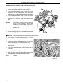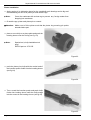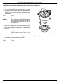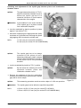
1
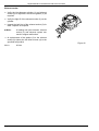
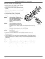
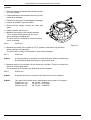
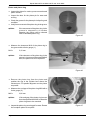
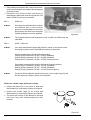
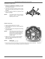
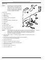
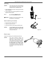
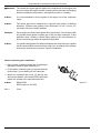
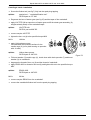
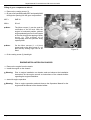
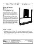
Repair Manual FR 125 MAX and FR 125 Junior MAX
EO2
REPAIR MANUAL
for ROTAX-engines type
FR 125 MAX
FR 125 Junior MAX
Version:
Engine configuration no.:
FR 125 MAX (21 kW)
37.125.1301
Version:
Engine configuration no.:
FR 125 Junior MAX (15 kW)
30.0125.130
Edition:
11 2000
Bombardier-Rotax GmbH
A-4623 GUNSKIRCHEN
Welser Strasse 32
AUSTRIA
http://www.rotax.bombardier.com
Page 1
Edition 11/2000
Repair Manual FR 125 MAX and FR 125 Junior MAX
Preface
This Repair Manual contains essential advice and data for professional maintenance and repair of the
ROTAX kart engines, type FR 125 MAX and FR 125 JUNIOR MAX.
The Repair Manual is based on the state of knowledge at the time of publication.
BOMBARDIER-ROTAX reserves the right to make technical modifications to the engine in view of further
development without updating this Manual.
All data and procedures in this Repair Manual are described to the best of our knowledge, however excluding
any liability.
We reserve all rights including technical modification and possibility of errors. Reprinting, translation or
copies, in whole or in part, authorized only after written permission by
BOMBARDIER ROTAX GMBH
Motorenfabrik
A-4623 Gunskirchen - Austria
Page 2
Edition 11/2000
Repair Manual FR 125 MAX and FR 125 Junior MAX
Table of contents
Preface ........................................................................................................................................................2
IMPORTANT INFORMATION .........................................................................................................5
Repeating symbols .....................................................................................................................................5
General precautions and safety information ................................................................................................5
Technical data .............................................................................................................................................7
Check and service intervals of engine components ....................................................................................8
Special tools, securing and sealing agents .................................................................................................9
Location of the engine serial number ........................................................................................................10
ENGINE REMOVAL FROM THE CHASSIS ............................................................................... 10
Engine removal ......................................................................................................................................... 11
Setting up the engine on the trestle ...........................................................................................................12
ENGINE DISASSEMBLY ........................................................................................................... 12
Removal of the radiator .............................................................................................................................12
Removal of the intake silencer and of the carburetor socket ....................................................................12
Removal of the electric starter ..................................................................................................................12
Removal of the centrifugal clutch ..............................................................................................................13
Removal of the cylinderhead cover and combustion chamber insert .......................................................14
Cylinder-removal .......................................................................................................................................14
Piston – removal .......................................................................................................................................14
Disassembly of the drive for the balance shaft and waterpump shaft. ......................................................15
Separation of the crankcase halves ..........................................................................................................15
Crankshaft removal ...................................................................................................................................16
INDIVIDUAL COMPONENT MAINTENANCE ............................................................................. 16
Crankcase .................................................................................................................................................16
Removal and refitting of bearings and oil seals .........................................................................................17
Crankshaft .................................................................................................................................................22
Replacement of the crankshaft repair set .................................................................................................23
Balance shaft ............................................................................................................................................24
Drive of the balance shaft ..........................................................................................................................24
Drive of the waterpump .............................................................................................................................25
Waterpump shaft .......................................................................................................................................25
Centrifugal clutch ......................................................................................................................................26
Bearing of the clutch drum assembly ........................................................................................................27
Clutch drum with chain sprocket assembly. ..............................................................................................28
Cylinder assembly .....................................................................................................................................29
Exhaust valve assembly ( only on engine version FR 125 MAX ) ..............................................................29
Disassembly of the exhaust valve (only on engine version FR 125 MAX) .................................................30
Installation of the exhaust valve (only an engine version FR 125 MAX ),.see fig. 39. .................................31
Exhaust socket ..........................................................................................................................................32
Reed valve assembly and carburetor flange .............................................................................................33
Cylinder .....................................................................................................................................................34
Piston and piston ring ................................................................................................................................35
Piston pin, needle cage, piston pin circlips................................................................................................36
Combustion chamber insert ......................................................................................................................37
Cylinder head cover ..................................................................................................................................37
Ignition unit ................................................................................................................................................38
Spark plug .................................................................................................................................................39
Starter reduction gear assembly ...............................................................................................................39
Page 3
Edition 11/2000
Repair Manual FR 125 MAX and FR 125 Junior MAX
Electric starter ...........................................................................................................................................39
Radiator ..................................................................................................................................................... 40
Intake silencer ...........................................................................................................................................40
Carburetor ................................................................................................................................................. 41
Fuel Pump ................................................................................................................................................. 42
Exhaust system ........................................................................................................................................42
ENGINE REASSEMBLY ............................................................................................................ 43
Crankcase assembly ................................................................................................................................ 43
Installation of the balance shaft and water pump drive .............................................................................. 45
Piston installation ......................................................................................................................................46
Cylinder installation ...................................................................................................................................47
Installation of combustion chamber insert and cylinder head cover .......................................................... 48
Checking and adjustment of the squish gap between piston and combustion chamber insert. ................49
Starter reduction gear installation ..............................................................................................................50
Centrifugal clutch installation .....................................................................................................................51
Pick-up coil for ignition unit - installation ....................................................................................................52
Spark plug - fitting ......................................................................................................................................52
Electric starter - installation .......................................................................................................................52
Radiator and intake silencer- installation ................................................................................................... 53
Fuel pump-installation ...............................................................................................................................53
Carburetor installation ...............................................................................................................................53
Filling of gear compartment with oil ...........................................................................................................54
ENGINE INSTALLATION ON CHASSIS...................................................................................... 54
Page 4
Edition 11/2000
Repair Manual FR 125 MAX and FR 125 Junior MAX
IMPORTANT INFORMATION
Repeating symbols
Pay attention without fail to the following symbols throughout the Manual emphasizing particular information.
▲ Warning:
Identifies an instruction, which if not followed may cause injury or endanger the life of the
rider, mechanic or third party.
■ Attention: Denotes an instruction which if not followed may result in severe damage of the engine. Noncompliance might lead under certain conditions to health hazards.
◆ Note:
Information useful for better execution and understanding of instructions.
➩ Denotes a working instruction
✔ Denotes a checking instruction
General precautions and safety information
▲ Warning:
The ROTAX engine Type FR 125 MAX is planned and has been developed solely for the use
in karts, which are exclusively run an specified tracks. Any applications beside that is not as
agreed and releases the manufacturer of any liability.
■ Attention: Information stated in this Manual are based on data and experience of experts, applicable at
standard working conditions. These guidelines are useful and necessary but they are never
a substitute for proper theoretical and practical training.
■ Attention: Replacement parts must meet the requirements defined by the engine manufacturer. This is
only warranted by the use of GENUINE-ROTAX parts and / or accessories ( see Replacement
parts list ). If using other than GENUINE ROTAX parts and / or accessories any warranty
granted by ROTAX will lapse.
■ Attention: modifications on engine and changes to sphere of engine (carburation, exhaust system etc.)
not approved by ROTAX releases the manufacturer of any liability and warranty.
■ Attention: to warrant proper repair, utilization of the specified special tools, fixtures, lubricating,-sealing,and securing agents is required.
■ Attention: Adhere to specified tightening torques without fail.
■ Attention: Removed sealing rings, gaskets, circlips, O-rings and oil seals have to be always renewed
at an engine overhaul.
■ Attention: Use only clean screws and nuts. Check thrustfaces and thread for damage. If doubtful use
new screws and nuts.
■ Attention: Decisive for life span and instant troublefree operation is to meet the specified schedule of
maintenance and to observe sundry technical data.
Page 5
Edition 11/2000
Repair Manual FR 125 MAX and FR 125 Junior MAX
■ Attention: Always secure engine safely on trestle.
■ Attention: After assembly verify components for tight fit and check engine for flawless operation.
■ Attention: Rectify minor defects without delay, thus preventing engine failure.
■ Attention: Pay attention without exception to all additional safety measures of the kart manufacturer.
Page 6
Edition 11/2000
Repair Manual FR 125 MAX and FR 125 Junior MAX
Technical data
Engine Type
Bore/Stroke
Displacement
Performance ( max.)
FR 125 MAX
FR 125 Junior MAX
Torque (max.)
FR 125 MAX
FR 125 Junior MAX
Idle speed
Speed limit
FR 125 MAX
FR 125 Junior MAX
Ignition unit
Spark plug
Electrode gap
Fuel
RON (min.)
Cooling system
Flowrate of the coolant pump
Coolant mixture
Coolant quantity
Engine lubrication system
Fuel mixing ratio
Lubrication of the balance shaft drive
Oil quantity for lubrication of balance shaft drive
Clutch
Clutch engagement speed
Power transmission from centrifugal clutch to the
rear axle of the kart
Chain dimension
Number of teeth of the drive sprocket
Weight (dry)
FR 125 MAX
FR 125 Junior MAX
54,0 mm / 54,5 mm
125,0 cm3
21 kW at 11.500 rpm
15 kW at 8.500 rpm
21 Nm at 8.750 rpm
17 Nm at 8.500 rpm
1.500 rpm
13.500 rpm (at operation on the track, under load)
12.200 rpm (at operation on the track, under load)
ATTENTION: Do not operate the engine without
load!
Breakerless, digital battery ignition, DENSO
NGK BR10EG, M14x1,25 or
DENSO IW31, M14x1,25
0,5 - 0,6 mm (NGK)
0,6 - 0,7 mm (DENSO)
Premium fuel, unleaded
95 octan
Liquid cooled, cooling circuit by integrated coolant
pump
22 l / min. at 11.000 rpm.
50% Antifreeze (al - compatible)
50% Water (distilled)
0,6 l
Mixture lubrication, super 2-stroke oil
1:50 (2% oil)
Motoroil SAE 15W- 40
0,05 l ( = 50 ml)
Centrifugal clutch, dry
Approx, 4000 rpm
Roller chain
7,75 x 4,6 x 4,5
11, 12, 13 or 14 teeth
Approx. 12 kg without silencer, carburetor, fuel
pump, radiator, muffler and battery
Table 1
Page 7
Edition 11/2000
Repair Manual FR 125 MAX and FR 125 Junior MAX
Check and service intervals of engine components
Component
Inspection or maintenance
schedule
Inspection before each kart
operation
Checking, remedy
Inspect for wear or deformation of
teeth,
renew as required
Exhaust system
After each kart operation
Apply oil against corrosion
Clean and apply oil,
Filter element in the intake silencer Latest after every 10 hours of
operation (depending on conditions Renew damaged filter element
of operation)
Coolant pump
Inspection before each kart
Inspect for exit of oil or coolant from
operation
the leakage bore in the crankcase.
In case of leakage let engine
overhaul carry out by an authorized
distributor or Service Center
Coolant elbow fitting on crankcase Inspection before each kart
Checking for tight fit and sealing,
and cylinder head cover.
operation
reseal with securing - and sealing
agent ERGO 4052 as required
Function of exhaust valve
Latest after every 10 hours of
Check for easy moving of the valve
operation
and correct fit of the single
componentes
Oil in the gear compartment
After every 2 hours of operation
Check oil level,
replenish as required
Drive gears for the balance shaft
After every 10 hours of operation
Inspect for wear,
renew worn parts
Oil in the gear compartment
After every 50 hours of operation or Oil change
at least once a year
Starter reduction gear assembly
Latest after every 10 hours of
Clean and apply grease on bearing
operation (depending on conditions seats
of operation)
Needle cage or bearing bush of
After every 2 hours of operation
Clean and grease,
clutch drum
replace worn parts
Friction lining of the fly weights
After every 10 hours of operation
Inspect for wear replace worn fly
weights
Insulating mat of aftermuffler
After every 10 hours of operation
Replace
Let the engine overhaul carry out by
Engine overhaul
After 50 hours of operation,
an authorized distributor or Service
Inspection of the following
components: Piston, piston pin and Center.
needle cage, oil seals of crank
shaft, drive of balance shaft,
sealing of the waterpump shaft
Table 2
Chain sprocket
▲ Warning:
Page 8
All maintenance and service activities have to be carried out by a trained mechanic only.
Edition 11/2000
Repair Manual FR 125 MAX and FR 125 Junior MAX
Special tools, securing and sealing agents
17
18
14
16
15
Figure 2
Figure 1
Pos.
1
2
3
4
5
6
7
ROTAX Teile-Nr.
277 380
277 362
276 015
944 230
676 010
676 020
676 030
8
9
10
676 040
676 035
876 762
fitting punch
insertion pusher
trestle assy
676 050
297 040
296 160
897 655
297 434
899 788
897 161
297 386
mounting plate
"ROTAX" - seal
gasket set
ERGO 4052
LOCTITE Anti Seize
LOCTITE 648
MOLYCOTE 111
SILASTIC 732 RTV
11
12
13
14
15
16
17
18
Tabelle 3
Page 9
Bezeichnung
crankshaft fixation tool
sprocket fixation tool
puller assembly
cover 12
fitting sleeve
fitting punch
fitting punch
Verwendung
for locking of the crankshaft
for fitting of the sprocket
to pull off the starter gear from the crankshaft
to protect the crankshaft end
installation of crankshaft oil seals
installation of waterpump oil seals
removal and installation of needle bushing for
starter reduction gear
for plain bearing of sprocket with 11 t.
piston pin circlip installation
engine support at service and maintenance
work
for ROTAX engines type 100 and FR 125 MAX
with registered serial no.
for the engine
securing agent, medium strength (2 gr.)
preventing fretting corrosion (50 ml.)
securing agent, high strength (5 gr.)
silicone grease (100 gr.)
sealing compound (100 gr.)
Edition 11/2000
Repair Manual FR 125 MAX and FR 125 Junior MAX
Location of the engine serial number
The engine number is imprinted on the clutch side crankcase half. Always state the engine
number on inquiries, when ordering replacement parts and in case of a warranty claim.
ENGINE REMOVAL FROM THE CHASSIS
◆ Note:
There is no need to remove the engine from the chassis to repair the
following components:
Centrifugal clutch
Cylinder assy with combustion insert and cylinder head cover
Exhaust valve
Reed valve
Piston
▲ Warning:
Before proceeding with repair work disconnect the battery (first the minus
pole. Caution: High voltage at ignition unit!
Page 10
Edition 11/2000
Repair Manual FR 125 MAX and FR 125 Junior MAX
Engine removal
▲ Warning:
Strictly observe removal and installation directives of the kart producer
➩ Let the engine cool down first
➩ Clean the Kart
➩ Disconnect the battery
▲ Warning:
Disconnect the battery only with
ignition switched off. First detach the
cable from the minus terminal and then
from the plus terminal
3
➩ Remove the exhaust springs and remove the
exhaust system
➩ Remove the lower engine pedestal brackets
➩ Remove the drive chain
➩ Disconnect the plugs for ignition coil (1), for pickup (2) and for the electric starter (3) from the cable
harness by releasing the respective catch.
■ Attention: Pull only on the plug, never on the cable
4
1
➩ Detach the ignition coil (4) by removal of the two
lock nuts (5)
5
➩ Pull off the fuel hose from the carburetor which
connects fuel pump with carburetor
➩ Pull off and plug the fuel hose from the fuel pump
which connects fuel tank with fuel pump.
▲ Warning:
2
Any spilled fuel must be absorbed at once with a bonding agent and disposed
off ecologically
➩ Slacken the clamps (6) and (7) and remove the
carburetor
Figure 3
8
6
▲ Warning:
When removing the carburetor fuel
could flow out. Do not smoke or allow
naked flames. Prevent any contact of
fuel with hot engine parts or equipment
– Risk of fire and explosion. Never
handle fuel in closed rooms.
7
➩ Remove the engine along with radiator and intake
silencer.
Figure 4
Page 11
Edition 11/2000
Repair Manual FR 125 MAX and FR 125 Junior MAX
Setting up the engine on the trestle
➩ Remove the engine pedestal from the cleaned engine, place the engine on the trestle
and secure with 4 fixing screws.
◆ Note:
Special tool – ”trestle assembly”
ROTAX part no.: 876 762, 676 050
ENGINE DISASSEMBLY
Removal of the radiator
➩ Loosen the two hose clamps on the coolant hose elbow fittings of the engine.
➩ Remove the lock nut (1) from radiator support on engine side.
➩ Pull off the hose along with the radiator from the lower 90° elbow fitting and drain the
coolant.
▲ Warning:
Risk of scalding when draining the coolant or removing the radiator cap at
operating temperature. Let the engine cool down first.
➩ Afterwards pull off the hose from the top elbow fitting.
Removal of the intake silencer and of the carburetor socket
➩ Pull off the impulse hose (2) from the fitting on the gear cover
➩ Remove the 5 Allen screws (M6) on the carburetor
socket (3)
➩ Remove the intake silencer (4) along with support
bracket (5) and fuel pump (6)
4
1
3
Removal of the electric starter
➩ Remove both Allen screw M6, securing the electric
starter on the crankcase
➩ Remove the electric starter (7)
5
6
7
2
Figure 5
Page 12
Edition 11/2000
Repair Manual FR 125 MAX and FR 125 Junior MAX
Removal of the centrifugal clutch
➩ Remove the spark plug
➩ Fit the crankshaft fixation tool (7) completely into
spark plug tapping (fig. 7)
◆ Note:
Special tool – ”crankshaft fixation tool”
ROTAX part no. 277 380
➩ Remove the hex. nut (1)
➩ Remove the thrust washer (2), clutch drum with
chain sprocket (3), needle cage (4) and the thrust
washer (5).
◆ Note:
Figure 6
On the chain sprocket with 11 teeth a bearing bush pressed into the chain
sprocket will be used instead of the needle cage (4).
➩ Remove the hex. nut (6)
➩ Incline the engine and with the crankshaft pointing
upwards, place the cover 12 (8) on crankshaft end.
7
◆ Note:
Special tool – ”cover 12”
ROTAX part No. 944 230
➩ Attach the puller assy (9) with 2 Allen screws M6 x
20 on the starter gear.
◆ Note:
◆ Note:
Special tool – ”puller assembly”.
ROTAX part no. 276 015
9
8
Turn in the M6 screws only so far into
the starter gear that a gap of at least 1
mm will remain between the screws
and crankcase.
➩ Press off the starter gear by turning-in the puller
screw M10 (fig 7)
➩ Remove the two Allen screws securing the
reduction gear cover (10) and remove the reduction
gear cover.
Figure 7
➩ Remove the starter reduction gear assembly (11)
and the trustwasher (12) underneath.
➩ Remove the crankshaft fixation tool (7) from the
spark plug tapping.
Figure 7.1
Page 13
Edition 11/2000
Repair Manual FR 125 MAX and FR 125 Junior MAX
Removal of the cylinderhead cover and combustion chamber insert
◆ Note:
If only the crankcase has to be taken to
pieces the completely assembled unit
of cylinder with reed valve, carburetor
socket, exhaust valve assy, exhaust
socket and combustion chamber insert
and cylinderhead cover, can be
removed from crankcase.
➩ Remove 4 Allen screws M6 (1) (fig. 8)
➩ Remove the cylinderhead cover (2)
➩ Take off both O-rings (3) and (4)
➩ Remove 5 Allen screws M8 (5) and lock washers
➩ Remove the combustion chamber insert (6) and
O-ring (7)
Cylinder-removal
➩ Remove 4 hex. nuts(8) with a A/F 11 spanner
➩ Remove the cylinder (9) from the crankcase
■ Attention: Take care not to damage the piston
Figure 8
➩ Remove the cylinder base gasket (10)
Piston – removal
➩ Force out the piston pin circlips (11) with a suitable
tool
■ Attention: Prior to the removal of the piston pin
circlips cover the crankcase opening
with a clean rag (fig. 9) to prevent piston
pin circlips from dropping into the
crankcase.
➩ Push out the piston pin (12) with the insertion pusher
◆ Note:
Special tool – ”insertion pusher”
ROTAX part no: 676 035
Figure 9
■ Attention: Always support the piston by hand (fig.
9) whilst pushing out the piston pin to
avoid a bending moment on the conrod.
➩ Remove the piston (13) along with needle cage
(14)
Figure 10
Page 14
Edition 11/2000
Repair Manual FR 125 MAX and FR 125 Junior MAX
Disassembly of the drive for the balance shaft and waterpump shaft.
➩ Remove the lowest Allen screw of gear cover (1)
and sealing washer and drain the oil.
▲ Warning:
Dispose of all operating fluids and
cleaning agents in accordance with the
effective environment issues.
➩ Afterwards remove the remaining 7 Allen screws
M6 and remove the gear cover (1) and the gasket
(2)
➩ Remove the waterpump pinion (3) and the
waterpump idle gear (4)
➩ Remove the needle pin (5) and the thrust washer
(6) from the waterpump shaft
➩ Remove the retaining rings (7) with a pair of snapring pliers
▲ Warning:
At reassembly use new retaining rings
without fail
Figure 12
➩ Remove the drive gear (8) from the crankshaft.
➩ Preheat the two balance gears (9) uniformly with a hot air gun and remove them from
the balance shaft
➩ Remove the O-ring (10) from the crankshaft.
Separation of the crankcase halves
11
➩ Remove all the 10 crankcase fasteners (M6)
➩ Take off the engine from the trestle
◆ Note:
◆ Note:
For the separation of the crankcase
halves the 2 Allen screws M6 x 60 of
the puller assembly must be used.
11
Special tool ”puller assembly”
ROTAX part no. 276 015
➩ Turn-in the 2 Allen screws (11) simultaneous thus
separating the crankcase halves uniformly.
Figure 13
➩ Remove the waterpump impeller (12) with the
pump shaft.
➩ Remove the balance shaft (13) from the crankcase
➩ Take off the gasket from the crankcase joint.
Figure 14
Page 15
Edition 11/2000
Repair Manual FR 125 MAX and FR 125 Junior MAX
Crankshaft removal
➩ Firmly hold the crankshaft with on hand. Remove
the crankshaft from the crankcase half by smart
blows with a mallet on the crankshaft end.
▲ Warning:
Be aware of the weight of the forced
out crankshaft. Risk of injury.
Figure 15
INDIVIDUAL COMPONENT MAINTENANCE
▲ Warning:
Any component with wear in excess of the specified wear limit or with
shortcomings detected at inspection which will impair engine operation
has to be replaced.
■ Attention: Risk of burns when handling hot engine parts.
◆ Note:
When taking dimensional readings in the order of accuracy of 0,1 mm or
even more precise, the temperature of the part must be between 20°C25°C.
Crankcase
➩ Clean both crankcase halves, ball bearings and all
bearing seals with a non-aggressive cleaning lotion.
■ Attention: Do not use degreasing or cold cleaning
agents.
➩ clean all sealing faces carefully.
1
1
✔ inspect both crankcase halves for cracks and
damage.
✔ inspect all sealing surfaces for damage.
✔ verify all threads for good condition.
✔ check the oil ducts (1) for the main bearings for
free passage and clear if necessary with
compressed air.
Page 16
Figure 16
Edition 11/2000
Repair Manual FR 125 MAX and FR 125 Junior MAX
✔ check the leakage bore (1) of the sealing system
of the waterpump shaft for free passage and if
necessary clear with compressed air.
✔ inspect the bore for the waterpump shaft for traces
of wear
1
✔ check all ball bearings and the needle bushing of
the starter reduction gear for easy motion and
pitting.
◆ Note:
Before checking the ball bearings and
the needle bushing oil them. The inner
race of the bearings must rotate freely
and without noise. In case of doubt
renew the bearings.
◆ Note:
If one of the two ball bearings of the crankshaft or balance shaft is defective
always renew both bearings.
◆ Note:
At replacement of the crankshaft bearings or the balance shaft bearings
renew all the associated oil seals too.
Figure 17
Removal and refitting of bearings and oil seals
➩ remove the oil seals (2) and (3) for the crankshaft with a suitable tool from the two
crankcase halves.
➩ remove the two oil seals (4) of the waterpump with
a suitable tool.
➩ detach the pick-up (5) of the ignition unit by removal
of the two Allen screws (6).
➩ remove the venting screw (7)
➩ remove the countersink screw (8) and the retaining
washer (9)
➩ preheat the two crankcase halves 30 min. in a hotair heater set to 100°C
▲ Warning:
Use heat protecting gloves when
handling the hot crankcase
Figure 18
Page 17
Edition 11/2000
Repair Manual FR 125 MAX and FR 125 Junior MAX
➩ take the preheated clutch side crankcase half (1)
from the heating unit and drop it on a plane wooden
plate. The impact with release the ball bearing of
the crankshaft (2) and of the balance shaft (3) from
the crankcase half.
➩ turn over the crankcase half and push out the
needle cage (4) with the fitting punch (see fig.19.1).
◆ Note:
special tool ”fitting punch”
ROTAX part no.: 676 030
◆ Note:
If the cooling water elbow will be
replaced, screw - in the new elbow
fitting only so far that one course of the
thread remains visible.
Figure 19
➩ Apply securing – and sealing compound ERGO
4052 on the degreased thread of the cooling water
elbow fitting (5).
◆ Note:
ERGO 4052
ROTAX part no. 897 655
➩ Screw - in and fix the elbow fitting into crankcase
in horizontal position until the securing – and
sealing compound has hardened.
Figure 19.1
➩ take the ignition side crankcase half (6) from the
heating unit and drop it on a plane wooden plate.
The impact with release the ball bearing (7) of the
crankshaft from the crankcase half.
➩ turn over to crankcase half and drop it with the
sealing surface of the gear cover on to the plane
wooden plate. The impact with release the ball
bearing (8) of the balance shaft from the crankcase
half.
◆Note:
The wooden plate must be with
recesses for the two dowel pins (9) as
well as for the locating pin (10) to
warrant a plane support of the
crankcase half on the wooden plate.
◆Note:
If the locating pin (10) needs renewal
remove it from the hot crankcase with
a pair of pliers.
Page 18
Figure 20
Edition 11/2000
Repair Manual FR 125 MAX and FR 125 Junior MAX
➩ let the crankcase halves cool down to room temperature (20°C)
➩ clean the bearing seat with a non-aggressive cleaning agent.
✔ measure the dia of the bearing seats in both crankcase halves.
✔ measure the outside dia of the new ball bearings
✔ calculate the interference fit between the ball bearings and the corresponding bearing
seat in the crankcase.
■ Attention: The interference between the ball bearing outer race and the corresponding
bearing seat in the crankcase must be at least 0,01 mm. If this is not the
case, the crankcase has to be replaced.
➩ preheat again both crankcase halves by hot air to
100°C
➩ take the preheated clutchside crankcase half from
the heating unit and place it with the crankcase
joint surface down on a plane wooden plate
2
➩ press the needle cage (1) fully home into the
crankcase half with the inscription of the needle
cage showing outwards, using the fitting punch (2).
◆ Note:
special tool, ”fitting punch”
ROTAX part no.: 676 030
1
➩ turn over the crankcase half
➩ apply grease between the sealing lip and the dust
lip of the oil seal (25 x 38 x 7) for the clutchside crankcase half.
➩ press oil seal fully home with the fitting sleeve from the inside of the crankcase half,
with the open side of the oil seal pointing inwards.
◆ Note:
special tool,”fitting sleeve”
ROTAX part no.: 676 010
◆ Note:
On an engine with the crankshaft installed, the oil seal can also be fitted
from outside with the help of the fitting sleeve.
Figure 21
➩ push ball bearing (3) for crankshaft fully home into
crankcase half, with the closed side of the ball cage
pointing towards the crankshaft
➩ push the ball bearing for the balance shaft fully
home, with the closed side of the ball cage pointing
towards balance shaft.
3
➩ let the crankcase half cool down.
Figure 22
Page 19
Edition 11/2000
Repair Manual FR 125 MAX and FR 125 Junior MAX
➩ Take the ignition-side crankcase half from the hot
air heater and place it with the crankcase joint
surface down on a plane wooden plate
➩ push the ball bearing (1) for the balance shaft fully
home, with the closed side of the ball cage towards
balance drive gear
➩ fit the retaining washer (2) and the countersink
screw (3) such that the chamfer side of the washer
points towards the screw.
1
3
2
Figure 23
➩ Apply grease between the sealing lip and the dust
lip of the oil seal (28x38x7) for the ignition-side
crankcase half.
5
➩ Press the oil seal (4) fully home with the fitting sleeve
(5) from the outside of the crankcase half with the
open side pointing towards the balance shaft drive.
◆ Note:
Special tool „fitting sleeve“
ROTAX part no.: 676 010
◆ Note:
On an engine with the crankshaft
installed the oil seal can also be fitted
from the outside with the help of the
fitting sleeve
◆ Note:
if the locating pin (9,see fig 20) has been removed, press the new locating
pin with the chamfering leading, fully home into the crankcase.
4
Figure 24
➩ Turn over the crankcase half
➩ Push the ball bearing (6) for the crankshaft fully
home into the crankcase half, with the closed side
of the ball cage pointing towards the crankshaft.
6
Figure 25
Page 20
Edition 11/2000
Repair Manual FR 125 MAX and FR 125 Junior MAX
➩ apply Molycotc 111 around the sealing lip of both
oil seals (10 x 26 x 7).
◆ Note:
Molycote 111
ROTAX part no. 897 161
1
➩ press the first oil seal with the fitting punch (1) fully
home such that the closed side of the oil seal is
visible.
◆ Note:
Special tool, ”fitting punch”
ROTAX part no.: 676 020
Figure 26
➩ Press the second oil seal with the fitting punch (2)
fully home such that the open side of the oil seal is
visible.
◆ Note:
Special tool, ”fitting punch”
ROTAX part no.: 676 020
➩ Let the crankcase half cool down.
2
Figure 27
◆ Note:
If the studs for the cylinder attachment will be replaced, the longer threaded
end of the studs has to be screwed in the crankcase. Secure the studs
with ERGO 4052 and tighten to the specified torque Mo1
◆ Note:
ERGO 4052
ROTAX part no. 897 655
M01 =
10 Nm
Page 21
Edition 11/2000
Repair Manual FR 125 MAX and FR 125 Junior MAX
Crankshaft
➩ clean the crankshaft with a non-aggressive cleaning agent.
➩ clean the taper for starter gear assy and the two threads from remains of the securing
agent
✔ inspect the crankshaft for damage or traces of wear on,
threads
taper
bearing seats
running surface for bearings of centrifugal clutch and piston pin
contact surface of oil seals
groove for the retaining ring of the drive gear
✔ measure the dia of the two main bearing seats
(M02), the bearing seat for the centrifugal clutch
(M03) and of the piston pin bearing dia.(M04)
M02 =
29,96 mm
M03 =
14,95 mm
M04 =
18,97 mm
M04
M02
M02
M03
✔ measure the axial clearance (M05) of the conrod
with a feeler gauge
M05 =
1,0 mm
✔ take readings of the radial clearance of the conrod
bearing (M06)
M06
M05
M06 =
0,05 mm
◆ Note:
If the wear limit is exceeded on M02 or
M03the complete crankshaft must be replaced. If the wear on M04, M05 or
M06 is above the limit, replacement of the crankshaft repair set is appropriate
(see section replacement by crankshaft repair kit!)
Figure 28
✔ check the out-of-roundness on the crankshaft
(M07)
M07 =
0,03 mm
◆ Note:
If the out-of-roundness on the
crankshaft (M07) is above the limit the
crankshaft must be realigned. (see
section replacement of crankshaft
repair set!)
M07
Page 22
Figure 29
Edition 11/2000
Repair Manual FR 125 MAX and FR 125 Junior MAX
Replacement of the crankshaft repair set
■ Attention: Repair of the crankshaft requires
special tooling and ought to be carried
out exclusively by a Repair Shop with
respective experience. If this repair
service is not available, replace the
complete crankshaft.
➩ press apart the crankshaft under a press
✔ inpect the bore for the crank pin in both crankshaft
webs for scoring
◆ Note:
If any of the bores shows scoring the
complete crankshaft has to be replaced.
Figure 30
M09
◆ Note:
The crankshaft repair set consists of:
conrod, crankpin, needle bearing and
the two thrustwashes.
■ Attention: The parts of the crankshaft repair set are matched and therefore
replacement is only permitted as a complete set.
➩ degrease the crankpin and the crankpin bore in the crankshaft webs.
➩ place one crankshaft web on a press, utilize a guide sleeve for the crankpin and press
the pin to positive stop into the crankshaft web
➩ arrange thrustwasher, needle bearing, the conrod and the second thrustwasher on the
crankpin.
➩ press together the two crankshaft webs to the specified dimension (M09)
M09 =
48,95 – 49,05 mm
✔ verify alignment of the crankshaft (see fig. 29)
◆ Note:
If the out of roundness on crankshaft is above the specifed limit the
crankshaft must be realigned.
◆ Note:
to align the crankshaft the two crankshaft webs may be squeezed or spread
accordingly on the required place. Crankshaft webs in a twisted position
can be corrected by blows on the webs with a soft hammer.
Page 23
Edition 11/2000
Repair Manual FR 125 MAX and FR 125 Junior MAX
Balance shaft
✔ Inspect the groove (1) for the retaining ring for
damage and wear
M10
M11
1
✔ Check the diameter of the bearing seats M10 and
M11 for wear
M10 =
14,94 mm
M11 =
24,94 mm
◆ Note:
If on any of the two bearing seats M10
or M11 the wear limit is exceeded, the
balance shaft must be replaced.
Figure 31
Drive of the balance shaft
✔ Inspect the balance gears for wear.
✔ Put the balance gears on the balance shaft and
crankshaft and check the serration fit between shaft
and gear for backlash
◆ Note:
If any of the balance shaft drive gears
shows cracks or if backlash of the
serration is perceptible, both drive
gears have to be replaced
✔ Inspect the gear toothing for traces of wear
◆ Note:
If distinct traces of wear are detected
on the tooth flanks of one gear, always
renew the complete pair.
Figure 32
✔ Verify the O-ring (2) for good condition.
◆ Note:
The balance gears (1) and the O-ring (2) ought to be renewed at least after
every 50 hours of operation.
▲ Warning:
A fracture of the balance gears will result in stopping of the waterpump,
leading to overheating of the engine and possibly to piston seizure.
Page 24
Edition 11/2000
Repair Manual FR 125 MAX and FR 125 Junior MAX
Drive of the waterpump
✔ Inspect the drive gear (1) the idle gear (2) and the
waterpump pinion (3) for cracks.
✔ Inspect the tooth flanks of the idle gear (2) and of
the waterpump pinion (3) for wear.
◆ Note:
At detection of wear on the flanks of the
idle gear (2) or waterpump pinion (3),
always renew both gears as a pair.
✔ Inspect the bore and the two thrust faces of the
idle gear (2) for traces of wear.
✔ Verify the groove in the waterpump pinion (3)
accommodating the needle pin (4), for good
condition.
Figure 33
Waterpump shaft
✔ Inspect the waterpump shaft (5) on the contact
surface of the two oil seals for wear. Renew as
required.
✔ Inspect the waterpump impeller (6) for damage or
deformation. Renew as required.
◆ Note:
When pressing-in the split sleeve (7)
pre-tension it so that impeller will not
be damaged.
Figure 34
Page 25
Edition 11/2000
Repair Manual FR 125 MAX and FR 125 Junior MAX
Centrifugal clutch
➩ Remove the 3 retaining rings (1) and the washers
(2) placed underneath.
■ Attention: Do not overstress the retaining rings at
removal
➩ Gradually remove the 3 flyweights along with the
engaged springs from the bearing pins on the
starter gear (5), utilizing a suitable tool (see fig.
35.1)
◆Note:
Never disengage the springs (4) with
the flyweights installed, as spring
removal in this situation might
overstress the springs.
➩ Disengage the 3 springs (4) from the flyweights
(3)
➩ Remove the 3 rubber sleeves (6) from the
supporting pins of the starter gear (5)
✔ Verify the friction lining on the flyweights (3). The
min. thickness of lining must be in no place below
the dimension M12.
M12 =
Figure 35
1,0 mm
✔ Check the bearing bore of flyweights for wear
(ovality)
◆Note:
If one of the flyweights is badly worn,
always replace all three of them.
✔ Check the springs (4) for fracture and
overstretching. Renew as required
◆Note:
If one of the springs is in bad condition,
replace always the three of them.
✔ Inspect the rubber sleeves (6) for wear. Renew as
required.
➩ Remove rests of LOCTITE from the conical bore
of the starter gear (5)
Figure 35.1
✔ Verify good condition of the conical bore of the starter gear (5)
✔ Inspect the toothing of the starter gear (5) for damage or deformation.
✔ Inspect the bearing pins of the starter gear (5) at bearing surface of the flyweights for
wear
✔ Verify the retaining ring (1) groove on the bearing pins of the starter gear (5) for good
condition.
Page 26
Edition 11/2000
Repair Manual FR 125 MAX and FR 125 Junior MAX
➩ Place the 3 rubber sleeves (6) on to the supporting
pins on the starter gear (5) (see fig 35)
➩ Fit the 3 fly weights (3) on the bearing pins of the
starter gear (see fig 35)
◆ Note:
When fitting the flywheel set, take care
not to deform the rubber sleeves (6)
(see fig,35)
➩ Engage the 3 springs on the fly weights, using a
suitable pair of pliers.
■ Attention: The springs must not be overstressed
during fitting.
Figure 36
➩ Place the washers (2) in position and fit the
retaining rings (1) (see fig,35)
1
■ Attention: Do not overstress the retaining rings
during removal and refitting. Renew as
required.
◆ Note:
The open side of the retaining rings (1)
should point outwards when fitted
Figure 37
Bearing of the clutch drum assembly
✔ Inspect the thrustwasher (3) and (7) for wear.
Renew as required.
✔ Inspect the needle cage (4) for wear. Renew as
required.
◆ Note:
For the chain sprocket with 11 teeth a
pressed-in plain bearing (5) is used
instead of the needle bearing (4)
◆ Note:
Starting of wobbling movements of the
clutch drum at idle speed indicate a
worn plain bearing (5).
Figure 37.1
Page 27
Edition 11/2000
Repair Manual FR 125 MAX and FR 125 Junior MAX
➩ Press out the bearing using the fitting punch
◆ Note:
special tool ”fitting punch”
ROTAX part no.: 676 040
➩ Place the new plain bearing (7) with the chamfered
end (8) on the chain sprocket (with 11 teeth) and
press it fully home into the chain sprocket.
7
8
Clutch drum with chain sprocket assembly.
✔ Inspect the chain sprocket for wear, Renew as
required.
✔ Inspect the surface on the inside of the drum
mating with the friction lining on the flyweights,
for wear. Renew as required.
Figure 37.2
➩ Clamp the sprocket fixation tool (1) at the flat bar
in a vice.
◆ Note:
special tool ”sprocket fixation tool”
ROTAX part no. 277 362
➩ Place the clutch drum with chain sprocket fitted
such on the respective centering pin of the fixation
tool, that the clutch drum can not rotate.
◆ Note:
on the chain sprocket with 11 teeth the
plain bearing has to be pressed out
first (the plain bearing is allowed to be
pressed-in only once)
➩ Remove the hex nut (5) for the chain sprocket
➩ Clean the clutch drum (4) and the hex, nut (5)
from remains of LOCTITE and degrease them
➩ Place the new chain sprocket on the respective
centering pin of the fixation tool (1)
➩ Insert the needle pin (3) into the chain sprocket
➩ Apply LOCTITE 648, on clutch drum (4) at support
face for hex. nut
◆Note:
LOCTITE 648
ROTAX part no. 899 788
➩ Place clutch drum (4) on the chain sprocket
Figure 38
➩ Fit the hex. nut (5) with the machined side towards the clutch drum and tighten to the
specified torque M13.
M13 =
Page 28
100 Nm
Edition 11/2000
Repair Manual FR 125 MAX and FR 125 Junior MAX
Cylinder assembly
◆ Note:
If the cylinder assembly has bean taking to pieces, it is recommended to
check the following components
Exhaust valve assembly ( only on engine version FR 125 MAX )
◆ Note:
The cylinder is equipped with a pneumatic exhaust control which optimizes
the performance characteristic. With rising engine speed the pressure of
the exhaust gas increases and withdraws the projecting exhaust valve from
the exhaust port at approx. 7.500 r.p.m.
◆ Note:
The optimum timing of the exhaust valve can be set only under load, at
operation on the racetrack. At engine operation on the racetrack different
temperatures of the exhaust gas and exhaust system will be reached as at
engine operation without load. The achieved temperatures have an essential
influence on exhaust gas pressure in the exhaust system and therefore on
the opening timing of the exhaust valve.
Page 29
Edition 11/2000
Repair Manual FR 125 MAX and FR 125 Junior MAX
Disassembly of the exhaust valve (only on engine version FR 125 MAX)
➩ disengage spring clip (1) and remove the valve cover (2) along with adjustment screw
(3) and the compression spring (4) underneath.
➩ Remove the two Allenscrews (5) and spring washers
➩ Remove the valve rod housing assy (6) and gasket (7) from the cylinder
➩ Remove the hose spring (8) from the bellows (9) and by applying by pressure remove
the bellows from the exhaust valve piston (10)
➩ Unscrew the valve piston (10) from the stud (11) and pull out the exhaust valve (12)
along with stud (11) and o-ring (13) from the valve rod housing (6)
➩ Clean all parts from oil and oil residues.
Figure 39
✔ Verify the exhaust valve (12) for easy movement in the cylinder.
Remove oil carbon deposits from the exhaust valve and cylinder as required.
✔ Verify the o-ring (13) for good condition.
◆ Note:
If the exhaust valve (12) or the stud (11) is going to be replaced, the stud
(11) must be secured again in the exhaust valve with LOCTITE 648 (15).
◆ Note:
LOCTITE 648
ROTAX part no. 899 788
■ Attention: Remove surplus LOCTITE from the stud and exhaust valve.
✔ Check the impulse bore in the valve rod housing (6) for free passage.
✔ Inspect the bellows (9) for cracks and porosity. Replace as required.
✔ Inspect the exhaust valve piston (10) for cracks or deformation caused by overheating,
replace as required.
✔ Inspect the valve cover (2) for cracks or deformation by overheating.
Page 30
Edition 11/2000
Repair Manual FR 125 MAX and FR 125 Junior MAX
Installation of the exhaust valve (only an engine version FR 125 MAX ),.see fig. 39.
➩ Slide the exhaust valve (12) with the fitted stud (11)
into the cylinder in the specific position as depicted
in the fig. 40.
➩ Put the o-ring (13) on the stud (11).
➩ Place a new gasket (7) such on the cylinder that
the impulse bore (14) on the cylinder corresponds
with the respective hole in the gasket (7).
12
➩ Attach the valve rod housing (6) with the recess
towards the exhaust socket on the cylinder, with
the Allen screws (5) secured by spring washers.
✔ Verify the exhaust valve for free movement
◆ Note:
If the exhaust valve is sticking or hard
to move the two fasteners of the valve
rod housing have to be slackened and retightened.
Figure 40
➩ Degrease the valve rod housing (6), the bellows (9) and the valve piston (10).
➩ Fit the bellows (9) over the valve rod housing (6) until the lip of the bellows is inserted
in the groove of the rod housing.
➩ Apply some ERGO 4052 (16) 0n end of stud (11)
◆ Note:
ERGO 4052
ROTAX part no. 897 655
■ Attention: Surplus ERGO can impair operation of the exhaust valve.
➩ screw the bellows exhaust valve piston (10) onto the stud (11) until your feel the ending
of the thread
➩ pull the bellows (9) over the exhaust valve piston (10) until the lip of the bellows is
inserted in the groove of the exhaust valve piston.
✔ Verify the exhaust valve for easy movement, improve if required by slight twisting of
valve piston (10) and bellows (9).
➩ Fit the hose spring (8) compression spring (4) and
valve cover with adjustment screw (3). Secure with
spring clip (1) on the cylinder (see fig 41).
◆ Note:
Turn the adjustment screw (3) into the
valve cover (2) so far that it ends flush
with the valve cover. This is the
standard adjustment.
1
Figure 41
Page 31
Edition 11/2000
Repair Manual FR 125 MAX and FR 125 Junior MAX
Exhaust socket
✔ Verify the joint between cylinder (1) and exhaust
socket (2) for tightness. Renew the gasket (3) as
required.
✔ Verify the tight fit of the exhaust socket (2) on the
cylinder
✔ Inspect the ball joint of the exhaust socket (2) for
wear. Replace as required.
◆ Note:
A leaking ball joint between exhaust
socket (2) and exhaust system can
result in engine malfunction.
➩ At replacement of the gasket (3) or the exhaust
socket (2) tighten the two Allen screws (4) to the
specified torque M14
M14 =
Page 32
Figure 42
20 Nm
Edition 11/2000
Repair Manual FR 125 MAX and FR 125 Junior MAX
Reed valve assembly and carburetor flange
➩ Remove the five Allen screws (5), the carburetor
flange (6) and the hose champ (7)
➩ Remove the reed valve (8) and gasket (9) from the
cylinder
✔ Inspect the rubber coating on the valve body (8)
for peeling off.
Replace the reed valve assy as required.
✔ Verify the Philips screws (10) for tight fit
✔ Inspect both reed petals (11) for cracks and
damage
◆ Note:
The reed petals (11) have to rest
neatly under slight pretension on the
valve body. Check by light gap
method. Renew reed petals as
required .
◆ Note:
The reed petals are not plane but
slightly bent. At replacement of the
reed petals ensure that the petals a fitted with pretension to close the
valve.
Figure 43
Secure the Philips screws (11) with LOCTITE 648.
◆ Note:
LOCTITE 648
ROTAX part no. 899 788
✔ Inspect the carburetor flange (6) for cracks, porosity or swelling.(see fig 43)
Renew as required
➩ Fit a new gasket (9), the reed valve assy (8) carburetor flange (6) and hose clamp (7),
with the Allen screws (5) on cylinder. Tighten the screws to the specified torque M15
(see fig 43)
M15 =
6 Nm
◆ Note:
With the two upper Allen screws (5) the support bracket for the radiator
has to be attached too.
With the three lower Allen screws (5) the support bracket for the intake
silencer has to be attached too.
Page 33
Edition 11/2000
Repair Manual FR 125 MAX and FR 125 Junior MAX
Cylinder
➩ Remove calcareous deposits from the water jacket
(1) of the cylinder.
➩ Clean exhaust port and exhaust valve duct (2) from
combustion deposits.
4
➩ Clean the o-ring groove (3) and inspect for damage
3
✔ Inspect all threads for good condition
✔ Ensure that all sealing surfaces are clean and
plane
✔ Inspect cylinder wall for wear
✔ Measure the conicity of the cylinder between
T.D.C. position of the piston ring and 3 mm
above top edge of exhaust port.
The wear limit for conicity M16 in this area must
not be exceeded.
M16 =
2
0,030 mm
1
Figure 44
✔ Measure the ovality of the cylinder at T.D.C. position of the piston ring and 3mm
above top edge of exhaust port.
The wear limit of ovality in this area M17 must not be exceeded.
M17 =
0,030 mm
◆ Note:
In case the conicity or ovality is in excess of the wear limit the cylinder may
be reworked by diamond-honing in a good repair shop.
✔ Measure the dia. of the cylinder 10 mm below top of cylinder. This dia. is decisive for
selection of the mating piston.
The wear limit for the cylinder dia. M18 must not be exceeded
M18 =
54,035 mm
◆ Note:
A cylinder with a dia. in excess of the wear limit has to be replaced
◆ Note:
The code of the cylinder size is imprinted on the top side (4) of cylinder
Cylinder size „A“
dia. 54,000 - 54,010mm
Cylinder size „AB“
dia 54,010 - 54,015mm
Cylinder size „B“
dia. 54,015 - 54,025mm
Page 34
Edition 11/2000
Repair Manual FR 125 MAX and FR 125 Junior MAX
Piston and piston ring
✔ Inspect the piston for cracks, pressure marks and
piston seizure.
✔ Inspect the bore for the piston pin for wear and
scoring
✔ Check the groove for the piston pin circlips for good
condition
✔ Verify free movement of the piston ring in the groove
◆ Note:
If the movement of the piston ring in the
groove is stopped by oil carbon
deposits, the groove can be cleaned
with a redundant piston ring
Figure 45
✔ Measure the clearance M19 of the piston ring in
the groove with a feeler gauge.(1)
M19 =
0,10 mm
◆ Note:
If the clearance of the piston ring in the
groove is in excess of the specified limit
M19, the piston has to be replaced.
1
Figure 46
➩ Remove the piston ring from the piston and
position the ring in the cylinder bore above the
exhaust port. For parallel aligment use the piston
as pusher.
✔ Measure the end gap of the piston ring M20 with a
feeler gauge (2)
M20 =
0,80 mm
◆ Note:
If the end gap of the piston ring is more
than the specified limit M20, at least the
piston ring has to be renewed.
✔ Inspect the piston ring securing pin for wear. Renew
the complete piston as required.
Page 35
2
Figure 47
Edition 11/2000
Repair Manual FR 125 MAX and FR 125 Junior MAX
➩ Take readings of the piston dia. using a micrometer,
at 20 mm from bottom end of piston and 90 degrees
to piston pin axis.
➩ Determine the piston-to-wall clearance by
deducting the piston dia. from the cylinder dia.The
wear limit M21 must not be exceeded.
M21 =
0,080 mm
◆ Note:
If the piston-to-wall clearance is above
the specified limit, a new oversize
piston of corresponding size (oversize
piston) has to be used or the complete
cylinder and piston must be replaced.
◆ Note:
The nominal piston-to-wall clearance in new condition is defined with the
value M22
M22 =
0,025 - 0,050 mm
◆ Note:
On a new piston find the piston dia printed in colour on the piston crown.
According to piston version find different printing on the piston.
Figure 48
On fully coated pistons find the following printing.
Printing 53,95= piston dia. 53,965 - 53,975 (standard)
Printing 53,96= piston dia. 53,975 - 53,985 (standard)
Printing 53,97= piston dia. 53,985 - 53,995 (oversize piston)
On partially coated pistons (see fig 48) find the following printing
Printing 53,97= piston dia. 53,965 – 53,975 (standard)
Printing 53,98= piston dia. 53,975 – 53,985 (standard)
Printing 53,99= piston dia. 53,985 – 53,995 (oversize piston)
◆ Note:
If a piston will be replaced, also the piston pin (1) the needle cage (2) and
the two piston pin ciclips (3) have to be replaced.
Piston pin, needle cage, piston pin circlips
✔ Inspect the piston pin (1) for traces of wear and
discoloration by overheating. Renew as required
✔ Inspect the needle cage (2) for cracks and
discoloration by overheating. Renew as required.
✔ The piston pin circlips (3) are allowed to be used
only once, they must renewed each time after
removal.
Figure 49
Page 36
Edition 11/2000
Repair Manual FR 125 MAX and FR 125 Junior MAX
Combustion chamber insert
✔ Clean the combustion chamber (1) from
combustion deposits and the water jacket surface
from calcerous deposits.
3
✔ Inspect the combustion chamber insert for cracks
and verify the spark plug thread (3) for good
condition.
2
✔ Verify the sealing surfaces for planeness and
inspect for damage.
◆ Note:
The sealing surface of the combustion
chamber insert is slight conical
beginning at dia. 63 mm
Figure 50
1
Cylinder head cover
✔ Inspect cylinder head cover for cracks
✔ Verify support face of the two o-rings (4 and 5) for
good condition.
✔ Verify tapping (6) for the cooling water elbow fitting
for good condition.
◆ Note:
If the cooling water elbow fitting on the
cylinder head cover will be replaced
screw-in the new elbow fitting only so
far that one course of the thread
remains visible.
➩ Apply securing -and sealing compound ERGO
4052 on the degreased thread of the cooling
water elbow fitting.
◆ Note:
4
6
ERGO 4052
ROTAX part no.897 655
➩ Screw-in the and fix the elbow fitting on the cylinder head into 90° position to direction
of travel until the securing -and sealing compound has hardened.
Page 37
5
Figure 50.1
Edition 11/2000
Repair Manual FR 125 MAX and FR 125 Junior MAX
Ignition unit
◆ Note:
Ignition timing is controlled by the digital
battery ignition unit consisting of the
trigger coil on the crankcase and an
ignition coil with the integrated
electronic. Manual ignition adjustment
is neither required nor possible.
6
7
9
8
Components:
1 trigger coil (pick up)
4
2 ignition coil
3 wiring harness
4 resistance spark plug connector
5
10
5 spark plug
6 on/off circuit breaker ( automatic fuse )
11
7 start button
2
8 battery
12
9 battery charger
10 electric starter assy
3
11 starter reduction gear assy
12 reduction gear cover
◆ Note:
1
If the engine will not start and if the ignition unit does not generate the
ignition spark or at indications that malfunctions of engine are caused by
the ignition unit verify the following components in the stated sequence or
trace error by method of elimination:
Figure 51
✔ check the battery charge, if necessary charge the battery or exchange it for a fully
charged one
✔ verify all plug connections and cable harness for good condition.
in case of doubt replace the cable harness
✔ replace the spark plug
✔ replace the resistance spark plug connector
✔ replace the on/off circuit breaker (automatic fuse)
✔ replace the start button
✔ replace the trigger coil ( pick up )
✔ replace the ignition coil
Page 38
Edition 11/2000
Repair Manual FR 125 MAX and FR 125 Junior MAX
Spark plug
◆ Note:
The engine from the serial production
will be supplied with a spark plug of type
NGK BR 10 EG or DENSO IW31
➩ remove deposits from mass- and centre electrode
with a wirebrush
✔ verify or adjust the electrode gap M23 of the spark
plug with a feeler gauge.
M23 =
0,5 - 0,6 mm (NGK BR 10 EG)
0,6 - 0,7 mm (DENSO IW 31)
M23
■ Attention: Bending of the mass electrode is only
permitted to a small degree.
Figure 52
Starter reduction gear assembly
1
➩ clean the starter reduction gear
2
✔ inspect the gears for wear
✔ check the function of the starter reduction gear
◆ Note:
In one direction the two gears can
counter-rotate freely, but in the other
direction of rotation the gears move
axially and finally lock.
Figure 53
Electric starter
Inspect the toothing (3) for deformation and wear
◆ Note:
The most common reason for
malfunction of the electric starter are
badly worn carbon brushes. In this
case replace all the parts included in
the repair kit of the electric starter. If
the starter cable (4) is defective it can
be renewed, but if any other
components of the starter are defective
the complete electric starter has to be
replaced.
4
3
Figure 54
Page 39
Edition 11/2000
Repair Manual FR 125 MAX and FR 125 Junior MAX
Radiator
➩ Clean the cooling fins of the radiator from dirt.
✔ Inspect the radiator (1) for cracks and damage.
◆ Note:
slight local deformation of the cooling
lamination can be rectified by
straightening out.
✔ Verify the gasket of radiator cap (2) for good
condition
✔ Check the coolant hoses (3) for porosity and
leakage
✔ Inspect the support bracket (5) of the radiator for
cracks
✔ Verify the rubber mount (6) for good condition
Intake silencer
Figure 55
✔ Inspect intake silencer bottow case (1) and intake
silencer top case (5) for cracks
✔ Inspect intake silencer tube (2) and carburetor
socket (6) for cracks and porosity.
➩ Clean the filter element with gasoline/oil mixture
✔ Inspect the filter element for cracks
◆ Note:
A filter element with cracks or signs of
decomposition has to be renewed.
◆ Note:
Prior to assembling of the intake
silencer lubricate the filter element with
common engine oil, and press out
surplus motor oil afterwards.
➩ Check support bracket (10) for cracks.
Figure 55.1
Page 40
Edition 11/2000
Repair Manual FR 125 MAX and FR 125 Junior MAX
Carburetor
◆ Note:
At malfunction of the engine caused by
the carburetor take the carburetor to
pieces, clean it and check some of the
components
➩ Take the carburetor into single parts as shown in
fig. 56 and clean the parts with gasoline.
✔ Clean and verify the fuel filter (30) for good condition
✔ Clean all the bores and ducts in the carburetor body
(1) and the jets (11,13,14,15,and 16) with
compressed air and verify free passage.
✔ Verify tight fit of the clip (4) on the jet needle (3)
✔ Verify tip of the valve needle (17) for good condition
➩ Reassemble the carburetor in accordance with
fig 56
◆ Note:
The gaskets (8,18,22,24,31 and 35) are
all included in the carburetor gasket set
and are be renewed at each repair of
the carburetor.
✔ Verify the position of the float bracket (19) in fitted
condition
◆ Note:
When you hold the carburetor upside
down (float chamber (23) and floats (21
not fitted yet) the unloaded float bracket
has to be in horizontal position and the
two ends of the bracket have to be at
the same level. Slightly bend ends of
the bracket as required.
◆ Note:
The word ”ALTO” on the floats (21) has
to be visible when the floats are
installed.
◆ Note:
Fit and adjust the Bowden cable for
actuating the carburetor piston in
accordance with the Operator’s Manual
of the engine.
◆ Note:
Set the adjustment screws (29) and
(34) according to the Operator’s
Manual of the engine.
Figure 56
Page 41
Edition 11/2000
Repair Manual FR 125 MAX and FR 125 Junior MAX
Fuel Pump
◆ Note:
Only the diaphragm and gasket set of
the full pump can be replaced. If the
cause for an engine malfunction is
suspected to be the fuel pump, it can
be found out only by replacement of the
pump.
✔ Verify the impulse line (1) the fuel supply line (2)
and the fuel outlet line (3) for good condition. Renew
as required.
◆ Note:
If the fuel pump is attached on the support bracket of the intake silencer
than oil condensate could settle in the impulse line during engine stops.
Figure 57
➩ Pull off the impulse line (1) from the fuel pump, remove any oil condensate and dispose
of it ecologically.
■ Attention: If the pump is attached in a position from where the oil condensate can not
drain, it could impair the operation of the fuel pump and consequently result
in engine malfunction or engine damage.
Exhaust system
◆ Note:
Distinguish between two different exhaust systems which differ mainly in
the diameter of the connecting bend between muffler and after-muffler.
✔ Inspect exhaust system for cracks
✔ Clean the ball joint from combustion deposits and
inspect for wear
✔ Verify the riveting of the cover (3 or 6) for tight fit.
◆ Note:
If the noise emission of the exhaust
system increases, the damping mat (2
or 5) may be renewed.
➩ grind open the riveting of the cover (3 or 6)
➩ remove the old damping mat
➩ roll the damping mat into a cylindrical shape and
fit it into the after-muffler
➩ fit the cover (3 or 6) and secure by rivets.
Figure 58
Page 42
Edition 11/2000
Repair Manual FR 125 MAX and FR 125 Junior MAX
ENGINE REASSEMBLY
■ Attention: Always renew removed gaskets, circlips, 0-rings and oil-seals at engine
repair.
■ Attention:
Risk of burns at handling of hot components
Crankcase assembly
➩ preheat both crankcase halves with bearings and oil-seals already fitted in a hot air
stove at 50°C for 30 min.
▲ Warning: Use heat-protective gloves when handling the hot crankcase
4
➩ place the preheated ignition-side crankcase half
with the surface for gear cover on a plane wooden
plate
➩ apply LOCTITE Anti-Seize on the main bearing
seats of the crankshaft
◆ Note:
2
3
1
LOCTITE Anti Seize
ROTAX part no. 297 434
➩ fully insert the crankshaft (1) into the ignition-side
crankcase half
➩ apply LOCTITE Anti-Seize on bearing seats of
the balance shaft
◆ Note:
LOCTITE Anti Seize
ROTAX part no. 297 434
➩ fully insert the balance shaft into the ignition-side crankcase half
Figure 59
➩ apply MOLYCOTE 111 on water pump shaft with the impeller already fitted, around
bearing seat.
◆ Note:
MOLYCOTE 111
ROTAX part no. 897 161
➩ fully insert the water pump shaft (3) into the ignition-side crankcase half
➩ place a new gasket (4) on the ignition-side crankcase half
◆ Note:
Page 43
No need to adjust the axial clearance of the crankshaft.
Edition 11/2000
Repair Manual FR 125 MAX and FR 125 Junior MAX
▲ Warning:
Always wear heat-protective gloves when handling the hot crankcase
➩ Place the preheated clutch-side crankcase half on the ignition side crankcase half.
➩ bolt together the two crankcase halves with 9 Allen screws
◆ Note:
Observe the diffent length of the Allen screws. Tighten the Allen screws to
the specified torque M24 in a crosswise sequence and with the torque
step-wise increasing, starting at the middle of the crankcase.
M24 =
10 Nm
➩ Let the crankcase cool down
➩ Place the crankcase on the trestle and secure with the 4 fixing screws.
◆ Note:
special tool, ”trestle assembly”
ROTAX part no.: 876 762, 676 050
➩ carefully cut off with a knife projecting parts of the
crankcase gasket at cylinder flange and cylinder
centering, but make sure not to damage the sealing
face.
Figure 60
Page 44
Edition 11/2000
Repair Manual FR 125 MAX and FR 125 Junior MAX
Installation of the balance shaft and water pump drive
➩ Insert the o-ring (1) into groove on the crankshaft
➩ preheat the balance gears (2) and (3) to 50°C
➩ fit the preheated balance gear (2) with hub collar
outwards, on the crankshaft such that the
markings (4) on crankshaft and balance gear align
➩ fit the preheated balance gear (3) with hub collar
inwards on the balance shaft such that the
markings (5) on balance shaft and balance gear
align.
◆ Note:
The balance gears (2) and (3) have to
mesh in the position in which the
markings (5) point towards ” high noon”
and the markings (4) point towards the
marking (6)
➩ Fit the drive gear (7) on the crankshaft
➩ Fit new retaining rings (8) on the balance shaft and
the crankshaft
Figure 61
■ Attention: Do not overstress the retaining rings during fitting.
✔ Verify proper fit of the retaining rings (8) in the
groove of balance shaft and crankshaft.
➩ fit the thrust washer (9) the needle pin (10) and the
water pump pinion (11) on water pump shaft.
6
✔ Verify proper fit of needle pin in recess of the water
pump pinion
➩ fit the water pump idle gear (12) on locating pin in
crankcase
5
➩ place a new gasket (13) on the crankcase
➩ attach the gear cover (14) with 8 Allen screws M6
x 25 and tighten to the specified torque M25
4
M25 =
10 Nm
◆ Note:
Use sealing rings on the oil drain screw and oil level screw (see fig 73).
Page 45
Figure 62
Edition 11/2000
Repair Manual FR 125 MAX and FR 125 Junior MAX
Piston installation
➩ Apply engine oil to lubrication ducts for the crankshaft main bearings and to big-end
conrod bearing as well as to piston pin and needle cage.
◆ Note:
Cover the crankcase with a clean rag to prevent any foreign matter from
dropping into crankcase.
➩ fit needle cage, piston and piston pin on conrod
■ Attention: Make sure to fit the piston such that the piston ring securing pin points
towards intake port.
➩ place a new circlip on a plane plate and push the
locating sleeve over the circlip (sec fig. 63)
◆ Note:
Special tool „circlip installation tool
assy“
ROTAX part no.: 676 035
Figure 63
➩ push the piston pin circlip with the conical end of
the insertion punch further into the locating sleeve
(sec fig 64)
Figure 64
➩ Turn a round the insertion punch and push circlip
further into locating sleeve until the circlip snaps
into the recess in the locating sleeve (see fig 65)
Figure 65
Page 46
Edition 11/2000
Repair Manual FR 125 MAX and FR 125 Junior MAX
➩ Place the circlip insertion tool such on the piston
that the open ends of circlip point to 6 o’clock
position
◆ Note:
The insertion punch centers itself in the
piston pin
➩ support piston with one hand and push the circlip
from the locating sleeve into the piston (see fig.
66)
✔ Verify proper fit of the circlip in piston groove and
correct position of circlip ends ( 6 o’clock position)
➩ fit the second circlip the same way and verify proper
fit
➩ remove the covering of the crankcase opening.
Figure 66
Cylinder installation
➩ place a new cylinder base gasket of 0,5 mm thickness on the crankcase
◆ Note:
The sealing face on the crankcase for
the cylinder flange must be plane,
otherwise it could lead to leakage in this
area of the cooling circuit.
➩ apply 2 stroke motor oil on piston contact surface
➩ turn the piston ring such that the ends of the ring
are on piston ring securing pin
➩ push the piston ring into the piston ring groove with
two fingers and fit the pre-assembled cylinder over
the piston on the crankcase
▲ Warning:
Pairing of piston and cylinder only such
that it results in the appropriate pistonto-wall clearance (refer to Section
”Cylinder” and “Piston“)
Figure 67
➩ attach the cylinder with 4 collar nuts and tighten
the nuts crosswise to the specific torque M26
M26 =
Page 47
24 Nm
Edition 11/2000
Repair Manual FR 125 MAX and FR 125 Junior MAX
Installation of combustion chamber insert and cylinder head cover
➩ Place the o-ring (1) into groove of cylinder
➩ Put on the combustion chamber insert (2) and
attach with 5 hex. screws M8 (3) and lock washers.
Tighten the screws crosswise to the specified
torque M27
M27 =
30 Nm
◆ Note:
When fitting the combustion chamber
insert (2) make sure that the o-ring (1)
rests proper in the groove and will not
get squeezed
➩ place the o-ring (4) on combustion chaber insert
➩ place the o-ring (5) into the groove of cylinder head
cover (6)
◆ Note:
Slightly grease the o-ring (5) so it will
remain better in the groove of the
cylinder head cover
Figure 68
➩ attach the cylinder head cover (6) with 4 Allen screws M6 (7) and tighten the screws
crosswise to the specified torque M28
M28 =
Page 48
10 Nm
Edition 11/2000
Repair Manual FR 125 MAX and FR 125 Junior MAX
Checking and adjustment of the squish gap between piston and combustion
chamber insert.
◆ Note:
The gap between the piston (in T.D.C.)
and the combustion chamber insert is
defined as squish gap and is of
essential influence on performance
characteristic of the engine.
■ Attention: A precondition for the exact checking
of the squish gap is a piston cleared
from combustion deposits.
➩ turn the crankshaft by hand to position of piston
approx.5 mm before T.D.C.
➩ bend a bit of soldering tin of appropriate dia. (M29)
as shown on fig 69 and insert it through the spark
plug tapping until it touches the cylinder wall
M29 =
1,5 mm (only for version FR 125 MAX)
2,0 mm (only for version FR 125 JUNIOR MAX)
◆ Note:
The squish gap has to be always
measured in the piston pin axis.
Measuring of this gap in intake / exhaust
direction would be falsified by the tilting
of the piston and is not permitted
therefore
Figure 69
➩ turn the crankshaft by hand into T.D.C. position
◆ Note:
By this action the soldering tin will be
squeezed between piston and
combustion chamber insert
➩ Remove the soldering tin from the combustion
chamber and measure the squeeze end (= squish
gap) with a vernier caliper
◆ Note:
This measuring procedure needs a vernier caliper of 1/100 mm precision
■ Attention:
The squish gap must be within the specified range M30
M30 =
1,05 mm +0,25/-0,15 mm (only for version FR 125 MAX)
1,45 mm +0,25/-0,15 mm (only for version FR 125 JUNIOR MAX)
Page 49
Figure 70
Edition 11/2000
Repair Manual FR 125 MAX and FR 125 Junior MAX
■ Attention: The smaller the squish gap the higher the compression of the engine and
the move critical the engine reaction on jetting of the carburetor at changing
ambient conditions (temperature, atmospheric pressure, humidity)
◆ Note:
It is recommended to set the squish to the larger end of the respective
range.
◆ Note:
The squish gap can be adjusted by a cylinder base gasket of different
thickness. Cylinder base gaskets of the thickness 0,3 mm, 0,4 mm, 0,5
mm and 0,8 mm are readily available.
Example:
On an engine a cylinder base gasket of the thickness 0,5 mm is fitted. With
this cylinder base gasket a squish gap of 0,8 mm was measured. In this
particular case it needs a cylinder base gasket of 0,8 mm thickness to
achieve a squish gap within the specified range M30
◆ Note:
If a cylinder base gasket of a different thickness has to be fitted, the cylinder
can be removed after removal of the 4 collar nuts. At refitting of the cylinder
observe the instructions in section ”Cylinder installation”
Starter reduction gear installation
➩ apply grease on bearing seats and on toothing of
the starter reduction gear assembly (2).
➩ Fit the starter reduction gear (2) together with the
thrust water (1) onto bearing in the crankcase.
➩ Attach the reduction gear cover (3) with the two
Allenscrews M6x25, secure with ERGO 4052 and
tighten the screws to the specied torque M31
◆ Note:
ERGO 4052
ROTAX part no. 897 655
M31 =
5 Nm
Page 50
Figure 71
Edition 11/2000
Repair Manual FR 125 MAX and FR 125 Junior MAX
Centrifugal clutch installation
➩ Screw the fixation tool (see fig 7) fully into the spark plug tapping
◆ Note:
special tool – ” crankshaft fixation tool”
ROTAX part no.277 380
➩ Degrease the bore of starter gear (see fig 35) and the taper of the crankshaft.
➩ apply LOCTITE 648 on taper bore of starter gear and fit the starter gear assembly (fly
weights already fitted) on the crankshaft taper.
◆ Note:
LOCTITE 648
ROTAX- part no 899 785
➩ remove surplus LOCTITE
➩ tighten the hex. nut (4) to the specified torque M32
M32 =
100 Nm
➩ apply Lithium-base grease
on crankshaft at the contact surface for the
needle cage (6) (or for plain bearing on sprocket
with 11 teeth).
◆ Note:
Lithium base grease
ROTAX part no. 897 330
Figure 72
➩ Fit thrust washer (5) needle cage (6), clutch drum with chain sprocket (7) and thrust
washer (8) on crankshaft.
➩ degrease the thread of hex. nut (9) and the thread of crankshaft
➩ apply ERGO 4052 on thread of hex.nut (9) and tighten this nut to the specified torque
M33
◆ Note:
ERGO 4052
ROTAX part no. 897 655
M33 =
60 Nm
➩ remove surplus ERGO from the crankshaft.
➩ remove the crankshaft fixation tool from the spark plug tapping.
Page 51
Edition 11/2000
Repair Manual FR 125 MAX and FR 125 Junior MAX
Pick-up coil for ignition unit - installation
◆ Note:
The pick-up coil for the ignition unit is attached with 2 Allen screws M6x16
on the sand-cast crankcase. On the crankcase in die-casting this pick-up
coil is attached with 2 taptite (self tapping) screws M6x16.
➩ position the pick-up coil such on the crankcase that the connection for the cable harness
points towards gear cover
➩ attach the pick-up coil for the ignition unit with the 2 Allen screws or taptite screws and
tighten the screws to the specified torque M34
M34 =
10 Nm
◆ Note:
If the two taptite screws will be fitted on an used crankcase take care that
the taptite screws will engage proper in the already cut thread courses.
◆ Note:
The ignition coil will be attached on the engine not before engine installation
onto chassis
Spark plug - fitting
➩ screw the spark plug into the tapping of the combustion chamber insert and tighten to
the specified torque M35
M35 =
24 Nm
Electric starter - installation
➩ grease the o-ring on the centering of electric starter.
➩ fit the electric starter in centering on crankcase by rotating the starter to and fro until
the toothing of the starter engages in starter reduction gear. Attach the electric starter
with the 2 Allen screws M6x30. Tighten the screws to the specified torque M36
M36 =
Page 52
10 Nm
Edition 11/2000
Repair Manual FR 125 MAX and FR 125 Junior MAX
Radiator and intake silencer- installation
◆ Note:
The support bracket for the radiator and the support bracket for the intake
silencer are attached on the cylinder together with the reed valve assy and
the carburettor flange (see section reed valve and carburetor flange)
➩ connect the radiator with the two coolant elbow fittings on the engine according to fig.
55 and attach the radiator on the support bracket (pos.5, fig 55)
■ Attention: The coolant fitting on the radiator and on the engine must not touch each
other. A flexible connection between engine and radiator must be
established.
➩ Install the intake silencer as depicted in fig 55,1 and attach on the assigned support
bracket (pos. 10, fig 55,1)
Fuel pump-installation
➩ attach the fuel pump with two Allen screws M6x20 and self-securing nuts on the
underside of the intake silencer support bracket.
◆ Note:
Install the full pump such that the fitting for the impulse line points downwards
and the fuel supply line points towards the driver seat.
Carburetor installation
➩ Push the carburetor fully home into carburetor flange and fasten with the hose clamp
on the carburetor flange
➩ Push the carburetor socket of the intake silencer over socket on carburetor and fasten
on carburetor with the clamp.
Page 53
Edition 11/2000
Repair Manual FR 125 MAX and FR 125 Junior MAX
Filling of gear compartment with oil
➩ Remove the venting screw (3)
➩ fill gear oil of specified quality M37 and quantity M38
through the opening into the gear compartment.
M37 =
SAE 30
M38 =
50 cm³
◆ Note:
The Allen screws (1) can be used for
verification of the oil level. With the
engine in horizontal position (without
engine pedestal) pour in oil until it starts
to flow out through the tapping of Allen
screw (1). This amount of oil
corresponds with the specified filling
capacity M38.
◆ Note:
3
1
On the Allen screws (1 = oil level
screw) and on the Allen screw (2 = oil
drain screw) sealing rings have to be
fitted.
2
Figure 73
➩ fit the venting screw (3) hand tight
ENGINE INSTALLATION ON CHASSIS
➩ Remove the engine from the trestle
➩ Install the engine on the chassis
▲ Warning:
Prior to engine installation on chassis read and observe the installation
instructions for the engine as well as instructions of the chassis builder
regarding the engine installation.
➩ start with engine operation
▲ Warning:
Page 54
Prior to engine operation read and observe the Operators Manual for the
engine and the Manual of the chassis builder.
Edition 11/2000