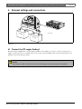
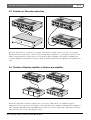
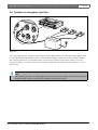
1
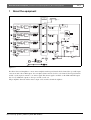
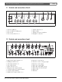
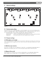
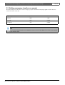
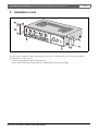
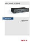
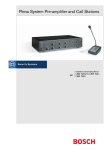
Plena Universal Pre-amplifier
Installation and Operating Manual
en
LBB 1920
Plena Universal Pre-amplifier | Installation and Operating Manual | Important safeguards
en | 3
Important safeguards
1 Read instructions - All the safety instructions for use
should be read before the system is operated.
2 Retain instructions - The safety instructions and
instructions for use should be retained for future
reference.
3 Heed warnings - All warnings on the unit and in the
operating instructions should be adhered to.
4 Follow instructions - All operating instructions and
instructions for use should be followed.
5 Cleaning - Unplug system units from the mains outlet
before cleaning. Do not use liquid cleaners or aerosol
cleaners. Use a damp cloth for cleaning.
6 Attachments - Do not use attachments not
recommended by the product manufacturer as they may
cause hazards.
7 Water and Moisture - Do not use this unit near water, for
example near a bathtub, washbowl, kitchen sink, or
laundry basket, in a wet basement, near a swimming
pool, in an unprotected outdoor installation or any area
which is classified as a wet location.
8 Accessories - Do not place this unit on an unstable stand,
tripod, bracket or mount. This unit may fall, causing
serious injury to a person and serious damage to the
unit. Use only a stand, tripod, bracket or mount
recommended by the manufacturer, or sold with the
product. Any mounting of the unit should follow the
manufacturer's instructions, and should use a mounting
accessory recommended by the manufacturer. An
appliance and cart combination should be moved with
care. Quick stops, excessive force, and uneven surfaces
may cause the appliance and cart combination to
overturn.
9 Ventilation - Openings in the enclosure, if any, are
provided for ventilation and to ensure reliable operation
of the unit and to protect it from overheating. These
openings must not be blocked or covered. The unit
should not be placed in a built-in installation unless
proper ventilation is provided or the manufacturer's
instructions have been adhered to.
10 Power sources - Units should be operated only from the
type of power source indicated on the marking label. If
you are not sure of the type of power supply you plan to
use, consult your appliance dealer or local power
company. For units intended to operate from battery
power, or other sources, refer to the "Installation and
User Instructions".
11 Grounding or polarisation - This unit may be equipped
with a polarised alternating current line plug (a plug
having one blade wider than the other). This plug will fit
into the power outlet only one way. This is a safety
feature. If you are unable to insert the plug fully into the
outlet, try reversing the plug. If the plug still fails to fit,
contact your electrician to replace your obsolete outlet.
Do not defeat the safety purpose of the polarised plug.
Alternatively, this unit may be equipped with a 3-wire
grounding type plug having a third (grounding) pin.
This plug will only fit into a grounding-type power
outlet. This is a safety feature. If you are unable to insert
the plug into the outlet, contact your electrician to
replace your obsolete outlet. Do not defeat the safety
purpose of the grounding-type lug.
Bosch Security Systems | 2003-09 | 3922 988 99482en
12 Power-Cord Protection - Power supply cords should be
routed so that they are not likely to be walked on or
pinched by items placed upon or against them, paying
particular attention to cords and plugs, convenience
receptacles, and the point where they exit from the
appliance.
13 Overloading - Do not overload outlets and extension
cords as this can result in a risk of fire or electrical shock.
14 Object and Liquid Entry - Never push objects of any
kind into this unit through openings as they may touch
dangerous voltage points or short-out parts that could
result in a fire or electric shock. Never spill liquid of any
kind on the unit.
15 Servicing - Do not attempt to service this unit yourself as
opening or removing covers may expose to dangerous
voltage or other hazards. Refer all servicing to qualified
service personnel.
16 Damage Requiring Service - Unplug the unit from the
outlet and refer servicing to qualified service personnel
under the following conditions:
• When the power-supply cord or plug is damaged.
• If liquid has been spilled, or objects have fallen into
the unit.
• If the unit has been exposed to rain or water.
• If the unit does not operate normally by following
the instructions for use. Adjust only those controls
that are covered by the instructions for use, as an
improper adjustment of other controls may result in
damage and will often require extensive work by a
qualified technician to restore the units to their
normal operation.
• If the unit has been dropped or the unit has been
damaged.
• When the unit exhibits a distinct change in
performance; this indicates a need for service.
17 Replacement Parts - When replacement parts are
required be sure the service technician has used
replacement parts specified by the manufacturer or parts
which have the same characteristics as the original part.
Unauthorised substitutions may result in fire, electric
shock or other hazards.
18 Safety Check - Upon completion of any service or
repairs to the units, ask the service technician to perform
safety checks to determine that the unit is in proper
operating condition.
19 Lightning - For added protection of the units during a
lightning storm, or when it is left unattended and unused
for long periods of time, unplug it from the wall outlet
and disconnect the cable system. This will prevent
damage to the unit due to lightning and power-line
surges.
Plena Universal Pre-amplifier | Installation and Operating Manual | About this manual
en | 4
About this manual
This manual provides all the information required to install and operate the unit.
Conventions
Warning
Follow these instructions to prevent personal injury.
Caution
Follow these instructions to prevent damage to the equipment.
Note
Read these instructions for tips and other useful information.
Safety precautions
Warning
Do not open the unit when it is connected to the mains. The unit contains non-insulated parts, which can
cause electric shock.
Caution
There are no user-serviceable parts inside the unit. Service must be done by qualified personnel.
Bosch Security Systems | 2003-09 | 3922 988 99482en
Plena Universal Pre-amplifier | Installation and Operating Manual | Table of contents
en | 5
Table of contents
Important safeguards..........................................................................................................................................................3
About this manual ..............................................................................................................................................................4
Safety precautions...............................................................................................................................................................4
Table of contents ................................................................................................................................................................5
1 About the equipment ........................................................................................................................................................7
1.1
Controls and connections (front) .............................................................................................................................8
1.2
Controls and connections (rear) ..............................................................................................................................8
2 Internal settings ..................................................................................................................................................................9
2.1
Priority mode setting ................................................................................................................................................9
2.2
Channel settings ........................................................................................................................................................9
2.2.1 Microphone or Line input ..................................................................................................................................9
2.2.2 Mic/Aux input selection .....................................................................................................................................9
2.2.3 Speech filter on/off ..............................................................................................................................................9
2.3
Setting emergency, insertion or cascade ..............................................................................................................10
3 Installation in rack ...........................................................................................................................................................11
4 External settings and connections .................................................................................................................................12
4.1
Connect the DC supply (battery) ..........................................................................................................................12
4.2
Connect a microphone or line-level source .........................................................................................................13
4.3
Insertion or Cascade connection ...........................................................................................................................14
4.4
Connect a Booster amplifier or System pre-amplifier ........................................................................................14
4.5
Connect an emergency input line .........................................................................................................................15
5 Operation .........................................................................................................................................................................16
5.1
Set Line input volume, treble and bass ................................................................................................................16
5.2
Line monitoring ......................................................................................................................................................16
6 Technical data ..................................................................................................................................................................17
6.1
Electrical ..................................................................................................................................................................17
6.2
Performance ............................................................................................................................................................17
6.3
Inputs ........................................................................................................................................................................17
6.4
Outputs .....................................................................................................................................................................18
6.5
Interconnection .......................................................................................................................................................18
6.6
Relays .......................................................................................................................................................................18
6.7
Environmental conditions ......................................................................................................................................18
6.8
General .....................................................................................................................................................................18
Bosch Security Systems | 2003-09 | 3922 988 99482en
Plena Universal Pre-amplifier | Installation and Operating Manual | Table of Contents
Bosch Security Systems | 2003-09 | 3922 988 99482en
en | 6
Plena Universal Pre-amplifier | Installation and Operating Manual | About the equipment
1
en | 7
About the equipment
Priority Mode
B/S JP109
Tel/EMG Override
Priority Control
S101
1mV
JP102
Bal.input
1/Line
200mV
P.S.
XLR
Speech filter
JP101
ON/OFF
A
Tone
Mic.
Pin 4
Aux
JP111
OFF
5-Pole Din
Over Ride
1V
JP110
Pin 5
Balanced Direct Output
200mV
monitoring
S102
1mV
Bal.input
2/Line
200mV
P.S.
XLR
Speech filter
JP103
ON/OFF
A,B,C,D Master
B
JP104
Mic.
Tone
Aux
JP112
OFF
2 1
3
4
3V
master
1V
Balanced Direct Output
200mV
(350mV)
O
In/Case Out
S103
1mV
Bal.input
3/Line
200mV
P.S.
XLR
Speech filter
JP105
ON/OFF
C
JP106
Mic.
Tone
Aux
JP113
OFF
1V
Master
Cascade
Blalanced Direct Output
Master Line Out
S301A
200mV
Insertion
S104
1mV
4/Line
XLR
200mV
P.S.
Speech filter
JP107
ON/OFF
Master
D
JP108
Bal.input
Master Mic. Out
Tone
Mic.
Aux
JP114
OFF
1V
Blalanced Direct Output
Insertion
Cascade
Emergency
Level
Preset
200mV
S301B
2 (ON)
F101
18V
1 (OFF)
VOX
JP301
VOX
DETECTOR
115/230V
1A
Ins/Casc/EMG In
F1
24V DC
F102
DC Out
Figure 1.1
The Plena Universal Amplifier is a mono mixer amplifier with 4 input channels. Each channel has 3 possible input
connections and a direct XLR output. You can adjust volume and tone level for each channel. The 4 input channels
and the cascade input are mixed to one master signal. This master signal is available on the XLR and DIN output
(mic. level). Additional outputs are the tape out and cascade out.
All pre-amplifier channels and the master output can be monitored with a headphone.
Bosch Security Systems | 2003-09 | 3922 988 99482en
Plena Universal Pre-amplifier | Installation and Operating Manual | About the equipment
en | 8
1.1 Controls and connections (front)
5
5
5
5
6
7
8
Plena Universal Pre-amplifier
1
1/Line
0 dB
2/Line
3/Line
4/Line
-6 dB
Master
Select
-20 dB
2
2
3
1
4
Master
Power
3
0
4
4
4
4
Figure 1.2
1
2
3
4
5
6
7
8
VU meter (LED bar)
Power on indication LED (green)
Power on/off
Tone control, channel 1 to 4
Volume, channel 1 to 4
Master volume
Channel selection for headphone
Headphone connection
1.2 Controls and connections (rear)
9
9
9
9
10
Dir.Out1
Dir.Out2
Dir.Out3
Dir.Out4
11
12
Ins/ Casc / Emgln
13
Ins/ Casc Out
14
Master Line Out
15
Master Mic. Out
115V
LBB 1920/00
8900 192 00005
115/230V~,50/60Hz
No.
Ins/Casc
+
14
3
3
5
1
5
14
4
2
3
5
2
-
GND
GND
1
1
3
14
+
-
2
14
3
14
3
5
3
5
3
5
230V
Apparatus delivired
connected for 230V-
16
Rated input
power: 25VA
T0,5AL250V
Warning
17
This apparatus must be earthed
L
EMG Out
DC In
DC Out
+24V-
+24V-
R
1/Line
1
2
2/Line
3
1
2
3/Line
3
1
2
4/Line
3
1
2
3
4
5
6
7
Figure 1.3
1
2
3
4
5
6
7
8
9
DIN (priority) input, channel 1 to 4
XLR input, channel 1 to 4
Cinch input, channel 1 to 4
Tape output (Cinch)
Earth connection screw
Emergency relay output (terminal
24 V DC backup power input (terminal
24 V DC output (terminal)
XLR for direct output, channel 1 to 4
Bosch Security Systems | 2003-09 | 3922 988 99482en
10
11
12
13
14
15
16
17
Insertion/ cascade switch
Insertion/ cascade / emergency input
Insertion/ cascade output
Master Line output (XLR)
Master Mic output (DIN, priority)
Mains voltage 115/ 230 V switch
Mains socket
Mains fuse
8
Plena Universal Pre-amplifier | Installation and Operating Manual | Internal settings
2
en | 9
Internal settings
LINE 3
LINE 4
CINCH
XLR
CINCH
DIN
LINE 2
XLR
DIN
CINCH
LINE 1
XLR
DIN
CINCH
XLR
DIN
CN106
S104
CN108
S103
S102
S101
MIC
MIC
MIC
MIC
LINE
LINE
LINE
LINE
CH4
CH3
CH2
CH1
SPEECH CH4
SPEECH CH3
JP105
SPEECH CH2
JP103
SPEECH CH1
JP101
OFF ON
JP108
OFF ON
JP106
OFF ON
JP104
OFF ON
JP102
AUX MIC
INPUT CH4
AUX MIC
INPUT CH3
AUX MIC
INPUT CH2
AUX MIC
INPUT CH1
JP110
OVERRIDE RELAY
OFF
PRIORITY
JP109
ACTIVE
SERIAL
BLOCK
OFF ON
JP114
CH-4
JP113
CH-4
JP112
CN107
20-1
CH-4
JP111
4 E 3 2 E 1
4 E 3 1 B 2
CH-4
B E 1 2 3 4 M
MIXING
Figure 2.1
2.1 Priority mode setting
The priority mode can be set with jumper JP109 to serial or blocking mode. You can activate the mixing mode for
channel 1 to 4 with jumpers JP111 to JP114. The jumper JP110 enables or disables the priority override contact for
the 4 input channels. This contact is available on the Master Mic output to pass through priorities.
- Serial mode(default) : Channel 1 has the highest priority and channel 4 the lowest.
- Blocking mode
: The first activated input channel has the highest priority and blocks all other channels.
- Mixing mode
: The channel is mixed to the master output irrespective of priority.
2.2 Channel settings
2.2.1 Microphone or Line input
If you connect a microphone to an input channel, the switch (S101 to S104) must be in the Mic position. This setting
activates the Phantom power supply. If you connect a line level source the switch (S101 to S104) must be set in the
line position.
2.2.2Mic/Aux input selection
If you use the 5-pole DIN or the 3-pole XLR input of a channel, the corresponding jumper (JP102, JP104, JP106 or
JP108) must be in the MIC position. If you use the Cinch input the jumper must be in the AUX position.
2.2.3Speech filter on/off
Each channel has a speech filter that can be enabled or disabled with the corresponding jumper (JP101, JP103,
JP105, and JP107). The speech filter improves speech intelligibility by cutting off the lower frequencies.
Bosch Security Systems | 2003-09 | 3922 988 99482en
Plena Universal Pre-amplifier | Installation and Operating Manual | Internal settings
en | 10
2.3 Setting emergency, insertion or cascade
The functionality of the insertion/cascade/emergency input is determined with jumper JP301 and the 'Ins/Casc'
switch at the back of the unit.
Input/output used for
Jumper JP301
Switch
Insertion
OFF
INS
Cascade
OFF
CASC
Emergency
ON
CASC
Note
If you use the emergency option, the emergency volume can be set with VR301. This volume is not affected
by the master volume.
Bosch Security Systems | 2003-09 | 3922 988 99482en
Plena Universal Pre-amplifier | Installation and Operating Manual | Installation in rack
3
en | 11
Installation in rack
Plena
0 dB
-6 dB
-20 dB
Powe
r
Unive
rsal P
re-am
1/Line
plifier
2/Line
3/Line
4/Line
Maste
r
Sele
ct
3 4
2
5
Maste
r
Figure 3.1
The universal pre-amplifier is delivered for table-top use, but you can mount it in a 19" rack. If you mount the
pre-amplifier in a rack, you must:
• use the mounting brackets delivered with the unit.
• remove the 4 feet from the bottom of the unit. (Without the feet the unit is 2U high).
Bosch Security Systems | 2003-09 | 3922 988 99482en
Plena Universal Pre-amplifier | Installation and Operating Manual | External settings and connections
4
en | 12
External settings and connections
ust be
earthe
d
Rated
Power input
T0.5 : 100VA
AL 25
0V
ppara
conn tus deliv
ected
ire
for 2 d
30V-
L
R
EMG
OUT
DC
IN D
C
OUT
Dir.O
ut1
Dir.O
ut2
Dir.O
ut3
Dir.O
14
3
5
ut4
Ins/Ca
sc/Em
gln
3
1
5
2
4
Ins/Ca
scOut
+24V
-
14
1/Lin
1
+24V
-
+
3
5
2
3
Ins/Ca
sc
GND
1
GND
1
e
-
Maste
r Line
Out
Maste
r Mic.
+
2
3
14
Line1
Out
3
5
2/Lin
e
115V-
14
2
3
5
14
3/Lin
e
Line2
3
5
Warnin
This
3
Line3
0
4/Lin
g
apparat
us must
be earthed
Rated
input
Power
:
T0.5AL 100VA
250V
230V-
Appar
conneatus delivir
cted
ed
for 230V-
L
e
4
EMG
+
12 V
D
Line
R
OUT
DC
4
IN DC
OUT
+24V+24V-
-
F
+
-
C
12 V
D
F = 1.5A
C
Figure 4.1
4.1 Connect the DC supply (battery)
The universal pre-amplifier has a 24 Vdc input (terminal screw), which you can use to connect a back up power
supply, e.g. batteries. You can earth the unit to increase the electrical stability of the system. The unit is protected
against reversal of the battery polarity.
Caution
The connection cable must have an in-line fuse. Use the type of fuse as mentioned in the illustration.
Bosch Security Systems | 2003-09 | 3922 988 99482en
Plena Universal Pre-amplifier | Installation and Operating Manual | External settings and connections
en | 13
4.2 Connect a microphone or line-level source
Dir.O
Dir.O
ut1
ut1
Dir.O
ut3
Dir.O
ut4
ut2
14
3
5
Ins/C
3
asc/E
mgln
1
5
2
4
Ins/C
ascO
Dir.O
ut3
14
3
5
+
2
3
Maste
asc
1
GND
-
r Line
Out
Maste
+
2
r Mic.
3
14
1/Lin
e
ut4
Out
3
5
14
2/Lin
e
3
5
ut
Ins/C
GND
1
Dir.O
14
ut2
Dir.O
Dir.O
LBB
1920/
8900
00
115/2192 00005
No. 30V~,50/60
Hz
3
5
14
3
5
Warni
ng
This
Ins/Ca
sc/E
mgl
3
1
5
2
4
3/Lin
0
tus must
be earthe
d
115V-
Rated
input
Power
: 25VA
T0.5AL
250V
EMG
R
Out
DC In
+24V
-
3
5
+
2
3
Ins/Ca
GND
1
GND
1
-
230V-
Appa
ratus
conne
delivi
red
cted
for 230V-
L
4/Lin
e
14
appara
e
DC Out
+24V
-
sc
+
2
3
14
1/Line
3
5
2/Line
GND
GND
GND
Cinch
180 5-pole DIN
180 3-pole XLR
Figure 4.2
All channels have 3 possible inputs, use one of these inputs to connect a microphone or a line-level source. The
XLR and DIN input are balanced, the stereo Cinch input is unbalanced and converted to mono. If you use an input
make sure that the internal switch settings are correct (refer to §2.2).
Note
If you want to use the priority feature, you must use a microphone or line-level source with a priority contact
on pin 4 and 5 of the 5-pole DIN plug.
Bosch Security Systems | 2003-09 | 3922 988 99482en
Plena Universal Pre-amplifier | Installation and Operating Manual | External settings and connections
en | 14
4.3 Insertion or Cascade connection
Dir.Out
Dir.Out
1
Dir.Out
1
2
Dir.Out
2
Dir.Out
Dir.Out
Dir.Out
4
Dir.Out
4
14
3
5
14
3
5
Ins/C
asc/Emg
3
1
5
2
4
ln
Ins/C
asc/Emg
3
1
5
2
3
3
Ins/C
ln
4
Ins/C
14
3
5
+
2
3
Ins/C
GND
14
ascO
ut
Master
asc
1
GND
1
-
Line
1/Line
ascO
ut
Ins/C
asc
GND
Master
Line
1
3
GND
-
Out
Master
Mic.
+
2
3
Master
2
Mic.
Out
LBB
1920
8900
/00
115/ 192 0000
230V
5
No.
~,50
/60H
z
3
5
14
3
5
Warn
ing
This
14
1/Line
3
5
2/Line
-
1
+
14
2
Out
3
14
+
3
5
appa
ratus
must
3/Line
be earth
ed
0
115V
- 230V
-
14
2/Line
Apparat
conn us deliv
ected
ired
for 230V
-
Rate
d
Powe input
T0.5Ar : 25VA
L 250V
LBB
1920
8900
/00
115/ 192 0000
230V
No.
~,50
14
3
5
Warn
This
ing
appa
ratus
must
3/Line
0
Out
DC In
be earth
ed
Apparatu
conn
s
ected delivired
for 230V
-
Rated
Powe input
T0.5Ar : 25VA
L 250V
L
EMG
4/Line
EMG
R
115V
- 230V
-
5
/60H
z
3
5
L
4/Line
Out
3
5
Out
R
DC Out
DC In
+24V
-
DC Out
+24V
-
+24V+24V-
Dir.Out
1
Dir.Out
2
Dir.Out
3
Dir.Out
14
3
5
4
Ins/C
3
1
5
2
4
asc/Emg
ln
Ins/C
ascO
14
+
3
5
2
-
ut
Ins/C
asc
GND
Master
Line
1
3
GND
1
-
Out
Master
Mic.
+
2
3
14
1/Line
EQU
ALIS
ER
Out
3
5
14
2/Line
LBB
1920
8900
/00
115/ 192 0000
230V
No.
~,50
115V
- 230V
-
5
/60H
z
3
5
14
3
5
Warn
This
3/Line
0
ing
appa
ratus
must
be earth
ed
Rated
Powe input
T0.5Ar : 25VA
L 250V
Apparatu
conn
s
ected delivired
for 230V
-
L
4/Line
EMG
R
Out
DC In
+24V
-
Figure 4.3
DC Out
+24V
-
Figure 4.4
If you use the insertion or cascade mode, you must set the 'Ins/Casc' switch, on the rear, in the correct position.
The insertion mode can be used to connect an external sound-processing device, e.g. an equaliser. To increase the
number of input channels, you must use the cascade mode to link pre-amplifiers. E.g. with 2 pre-amplifiers, the
second preamplifier has 8 channels on its master output (4 channels from the first pre-amplifier and 4 channels of its
own).
4.4 Connect a Booster amplifier or System pre-amplifier
Dir.O
Dir.O
ut1
ut1
Dir.O
Dir.O
ut2
ut2
Dir.O
Dir.O
ut3
ut3
Dir.O
Dir.O
ut4
ut4
14
3
5
1
5
2
14
Ins/C
asc/E
mgln
3
4
14
3
5
+
2
3
Ins/C
GND
ascO
1
Maste
-
r Line
+
2
14
14
3
5
Warni
This
3/Lin
e
0
ng
appara
tus must
be earthe
d
115V-
Rated
Power input
T0.5AL: 25VA
250V
3
Ins/C
asc
GND
Maste
r Line
1
GND
-
2
R
Out
3
5
LBB
1920/
8900
00
115/2192 00005
14
2/Lin
e
No. 30V~,50/60
3
5
14
3
5
Warni
This
3/Lin
ng
appara
tus must
Out
DC In
115V-
EMG
e
R
DC Out
Out
DC In
+24V
-
+24V
-
plifier
Appa
conneratus delivir
cted
ed
for 230V-
L
4/Lin
Powe
r
Plena
Sys
0 dB
-6 dB
-20 dB
Powe
230V-
Hz
Rated
Power input
T0.5AL: 25VA
250V
be earthe
d
e
0
EMG
e
Out
Maste
r Mic.
+
14
e
230V-
Appa
conneratus delivir
cted
ed
for 230V-
+24V
-
0 dB
-6 dB
-20 dB
2
L
4/Lin
Plena
Mixer
Am
+
3
1/Lin
LBB
1920/
8900
00
115/2192 00005
No. 30V~,50/60
Hz
3
5
Ins/C
ascO
ut
3
5
1
Out
3
5
2/Lin
e
Ins/C
asc/E
mgln
4
14
Maste
r Mic.
14
1
5
Out
3
1/Lin
e
3
ut
asc
1
GND
3
5
2
Ins/C
DC Out
+24V
-
tem Pre
-amplifi
er
r
Sele
/Line
ct
CD
AUX
Z1
Z2
+
Z3
Z4
Z5
+
Z6
Figure 4.5
The master output and/or the direct outputs can be connected to a Plena Booster to amplify the signal to
loudspeaker level. You can also use the outputs to connect the universal pre-amplifier to the System pre-amplifier or
other equipment. The Master Mic output (DIN) has a priority relay contact on pin 4 and 5. This relay is activated
when a priority contact of one of the inputs is closed.
Bosch Security Systems | 2003-09 | 3922 988 99482en
Plena Universal Pre-amplifier | Installation and Operating Manual | External settings and connections
en | 15
4.5 Connect an emergency input line
Dir.O
ut4
Dir.O
ut1
Dir.O
ut2
Dir.O
ut3
Dir.O
Ins/C
14
asc/E
3
5
Ins/C
asc/E
mgln
1
5
2
4
mgln
14
2
3
Ins/C
asc
GND
Maste
1
GND
-
r Line
Out
Maste
+
2
14
e
2/Lin
ut
r Mic.
Out
3
5
14
e
LBB
1920/
8900
00
115/2192 00005
No. 30V~,50/60
Hz
3
5
14
3
5
Warni
ng
This
Ins/C
M
asc
-
+
3
ascO
1
Ins/C
ascO
ut
3
5
1
1/Lin
Ins/C
GND
ut4
3
3/Lin
e
0
appara
tus must
be earthe
d
115V
- 230V
-
Rated
input
Power
:
T0.5AL 25VA
Appa
ratus
conne
delivi
red
cted
for 230V
-
250V
L
4/Lin
e
EMG
R
Out
DC In
+24V
-
+
DC Out
+24V
-
2
3
14
3
5
14
3
5
3/Lin
e
Figure 4.6
You can use this input for emergency announcements and/or signals. This line is activated when the signal is above
a certain threshold (VOX). When the line is activated it has the highest priority and overrules all input channels.
The emergency line has its own internal volume control and is not affected by the master volume. To set the
emergency volume, refer to §2.3. If you use the emergency input make sure that the internal settings are correct
(refer to §2.2).
Note
The emergency input has a 24 V relay output (screw terminal), which is activated on the VOX of the input. An
additional 24 Vdc output (screw terminal) is available to power external relays.
Bosch Security Systems | 2003-09 | 3922 988 99482en
Plena Universal Pre-amplifier | Installation and Operating Manual | Operation
5
en | 16
Operation
Plena
0 dB
-6 dB
-20 dB
Unive
rsal P
re-am
plifier
1/Li
ne
2/Line
Powe
r
3/Line
4/Line
Maste
r
Selec
t
2 3
1
4
Maste
r
Figure 5.1
5.1 Set Line input volume, treble and bass
You can adjust the volume, treble and bass for each channel by turning the corresponding knobs. To change the
overall volume you must turn the 'Master' volume knob.
5.2 Line monitoring
The line monitoring can be used to listen to a single channel or the master channel. To do so connect a headphone
at the front of the pre-amplifier. Use the 'Select' switch to select a channel.
Note
The VU-meter always shows the volume for the selected channel.
Bosch Security Systems | 2003-09 | 3922 988 99482en
Plena Universal Pre-amplifier | Installation and Operating Manual | Technical data
6
Technical data
6.1 Electrical
Mains voltage
Max mains power consumption
Battery voltage
Max battery current
230/115 Vac, ±15 %, 50/60 Hz
25 VA
24 Vdc, +20 %/-10 %
1A
6.2 Performance
Frequency response
Distortion
Bass control
Treble control
Line separation at 1 kHz
Priority mute
50 Hz - 20 kHz (+1/-3 dB)
<0.5 %
±10 dB at 100 Hz
±10 dB at 10 kHz
>70 dB
>40 dB
6.3 Inputs
Mic/Line inputs 1-4 (3-pin XLR/5-pin DIN, balanced)
Sensitivity
1 mV (microphone), 200 mV (line)
Impedance
>1 kOhm (microphone), >5 kOhm (line)
S/N (flat at max volume)
>63 dB (microphone), >70 dB (line)
S/N (flat at min volume/muted)
>75 dB
CMRR
>40 dB (50 Hz - 20 kHz)
Headroom
>25 dB
Speech filter
-3 dB at 315 Hz, high-pass, 6 dB/oct
Phantom power supply
16 V via 1.2 kOhm, in microphone mode only
Line inputs 1-4 (Cinch, unbalanced, stereo converted to mono)
Sensitivity
200 mV
Impedance
22 kOhm
S/N (flat at max volume)
>70 dB
S/N (flat at min volume/muted)
>75 dB
Headroom
>25 dB
Bosch Security Systems | 2003-09 | 3922 988 99482en
en | 17
Plena Universal Pre-amplifier | Installation and Operating Manual | Technical data
6.4 Outputs
Direct outputs 1-4 (3-pin XLR, balanced)
Nominal level
Impedance
1V
<100 Ohm
Master output (3-pin XLR, balanced)
Nominal level
Impedance
1V
<100 Ohm
Master output (5-pin DIN, balanced)
Nominal level
Impedance
4 mV (microphone level)
<100 Ohm
Tape output (Cinch, 2x mono)
Nominal level
Impedance
350 mV
<1 kOhm
Headphone output (6.3 mm jack stereo, signal mono)
Nominal level
3V
Impedance
<100 Ohm
6.5 Interconnection
Interconnection/emergency input (3-pin XLR, balanced)
Sensitivity
200 mV (interconnection)
100 mV - 1 V adjustable (emergency)
Impedance
>10 kOhm
VOX threshold
45 mV (emergency)
Interconnection output (3-pin XLR, balanced)
Nominal level
200 mV
Impedance
<100 Ohm
6.6 Relays
Priority relay contacts
Emergency relay contacts
DC supply output voltage
30 V, 1 A
30 V, 1 A
24 V, 250 mA max
6.7 Environmental conditions
Operating temperature range
Storage temperature range
Relative humidity
-10 to +55 °C
-40 to +70 °C
<95 %
6.8 General
EMC emission
EMC immunity
Dimensions
Weight
acc. to EN 55103-1
acc. to EN 55103-2
100 x 430 x 270 mm (19" wide, 2U high)
approx. 5 kg
Bosch Security Systems | 2003-09 | 3922 988 99482en
en | 18
For more information visit
www.boschsecuritysystems.com
© Bosch Security Systems B.V.
Data subject to change without notice
2003-09 | 3922 988 99482en