1
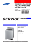
Safety • Assembly • Operation • Tips & Techniques • Maintenance • Troubleshooting • Parts Lists • Warranty
A
O
AL
Two-Stage Snow Thrower-
E, F Style
iMPORTANT
READ SAFETY
RULES AND iNSTRUCTiONS
CAREFULLY
BEFORE
OPERATION
Warning: This unit is equippedwith an internalcombustionengineand shouldnot be usedon or nearany uniiprovedforest-covered,brushcoveredor grass-coveredland unlesstheengine'sexhaustsystemis equippedwith a sparkarrestermeetingapplicablelocalor statelaws(if any).
If a sparkarresteris used,it shouldbe maintainedin effectiveworkingorder by the operator.In theState of Californiathe aboveis requiredbylaw
(Section4442 of the CaliforniaPublicResourcesCode). Otherstatesmay havesimilarlaws.Federallaws applyon federallands.A sparkarrester
for the muffleris availablethroughyour nearestengineauthorizedservicedealeror contactthe servicedepartment,RO. Box361131Cleveland,
Ohio 44136-0019.
MTD LLC, P.O. BOX 361131 CLEVELAND,
PRINTEDIN U.S.A
OHIO 44136-0019
FORMNO. 769-01275C
06/13/2005
This Operator's Manual is an important part of your new snow thrower, it will help you assemble,
prepare and maintain the unit for best performance.
Please read and understand what it says.
Table of Contents
Safety Labels ......................................................
Safe Operation Practices ...................................
Setting Up Your Snow Thrower ..........................
Operating Your Snow Thrower ...........................
MakingAdjustments
.........................................
3
4
6
8
12
Maintaining Your Snow Thrower ......................
Off-SeasonStorage
...........................................
Trouble- Shooting .............................................
illustrated Parts List .........................................
Warranty ............................................
14
18
19
20
Back Cover
Finding and Recording Model Number
BEFOREYOU START ASSEMBLING
YOUR NEW EQUIPMENT,
please locate the model plate on the equipment and copy the
information to the sample model plate provided to the right.
You can locate the model plate by standing at the operating
position and looking down at the rear of the deck. This
information will be necessary to use the manufacturer's web
site and/or obtain assistancefrom the Customer Support
Department or an authorized service dealer.
www.mtdproducts.com_
IViTD
LLC
P. O. BOX 361131
CLEVELAND,OH 44136
330-220-4683
8oo=8oo=731
o
J
Customer Support
Please do/VOTreturn
the unit to the retailer from which it was purchased,
without first contacting Customer Support.
If you have difficulty assembling this product or have any questions regardingthe controls, operation or maintenanceof this unit,
you can seek help from the experts. Choose from the options below:
1. Visit mtdproducts.com
for many usefulsuggestions.Clickon
CustomerSupportbutton and youwill get the optionsreproducedin
the screenshot below.Clickon the appropriatebutton and help is
immediatelyavailabb.
.
Theengine manufacturer is responsiblefor all engine-relatedissues
with regardto performance,power-rating,specifications,warrantyand
service. Pleasereferto theengine manufacturer'sOwner's/Operator's
Manual,packedseparatelywith yourunit, for moreinformation.
2. Phonea Customer Support Representative at 1(800)800-7310.
Ya_d_Man
Yard Machi_ea
Maltreats OHHne
Pa_50eHne
2
$e_ce
Locater
1. KEEPAWAYFROMROTATING
IMPELLER
ANDAUGER.CONTACT
WITHIMPELLER
OR
AUGERCANAMPUTATE
HANDSANDFEET.
TOOLTOUNCLOG
, USECLEAN-OUT
DISCHARGE
CHUTE.
iil _I ii_ _ i _iii_!i _ _ii_ ii
CLUTCH
LEVERS,
STOPENGINE,
3. DISENGAGE
ANDREMAINBEHINDHANDLES
UNTILALL
MOVINGPARTSHAVESTOPPEDBEFORE
UNCLOGGING
ORSERVICINGMACHINE.
,
TOAVOIDTHROWNOBJECTS
INJURIES,
NEVER
DIRECT
DISCHARGE
ATBYSTANDERS.
USEEXTRA
CAUTION
WHENOPERATING
ON
GRAVELSURFACES.
5. READOPERATOR'SMANUAL.
WARNING
This symbol points
out importantsafety
instructionswhich, if
not followed,could
endangerthe personal
safety and/or property
of yourselfand others.
Read and follow all
instructionsin this
manual beforeattemptingto operate
this machine. Failure
to comply with these
instructionsmay result
in personalinjury.When
you see this symbol.
HEED ITS WARNING!
A chute clean-outtool is fastenedto the top of the
augerhousingwith a mountingclip. Thetool is designed
to cleara chuteassemblyof ice and snow.
This item is fastenedwith a cabletie at the factory.Cut
the cabletie beforeoperatingthe snowthrower.
_
hands
to clear
a clogged
chute
ARNING:
Never
use your
assembly. Shut off engine and
remain behind handles until
all moving parts have stopped
before using the clean-out tool
to clear the chute assembly.
3
Your Responsibility
Restrict the use
of this power machine
to persons who read,
understand
and follow the warnings
and instructions
in this manual
and onthe machine.
WARNING: Engine Exhaust, some of its constituents, and certain vehicle components contain or emit chemicals known to State of Californiato cause cancer and
birth defects or other reproductiveharm.
DANGER: This machine was built to be operated according to the rules for safe operation in this
manual. As with any type of power equipment, carelessness or error on the part of the operator can
result in serious injury. This machine is capable of amputating hands and feet and throwing objects.
Failureto observe the following safety instructions could result in serious injury or death.
Training
Preparation
1. Read,understand,andfollowall instructionson the
machineandin the manual(s)beforeattemptingto
assembleand operate.Keepthis manualina safe placefor
futureandregularreferenceandfor orderingreplacement
2.
3.
WARNING
This symbol points
out importantsafety
instructionswhich, if
not followed,could
endangerthe personal
i safety and/or property
I ofyourselfand others.
Read and follow all
instructionsin this
manual beforeattemptingto operate
i this machine. Failure
I to comply with these
instructionsmay result
i in personalinjury.When
you see this symbol.
4.
5.
6.
7.
1. Thoroughlyinspectthe area wherethe equipmentis to be
used. Removeall doormats,newspapers,sleds, boards,
wiresand otherforeignobjects,whichcould be tripped over
or thrown bythe auger/impeller.
parts.
2. Alwayswearsafetyglasses or eye shieldsduringoperation
Be familiarwithall controlsandtheir properoperation.
andwhile performingan adjustmentor repairto protectyour
Knowhowto stopthe machineanddisengagethem quickly.
eyes. Thrownobjectswhich ricochetcan cause serious
Neverallowchildrenunder14 yearsoldto operatethis
injury to the eyes.
machine.Children14 yearsold andovershouldread and
understandthe operationinstructionsand safetyrulesin
3. Do not operatewithoutwearingadequatewinterouter
this manualand shouldbe trainedand supervisedbya
garments.Do not wearjewelry, long scarvesor other
parent.
loose clothing,whichcould becomeentangledin moving
Neverallowadultsto operatethis machinewithoutproper
parts. Wearfootwearwhich will improvefooting on slippery
instruction.
surfaces.
Thrownobjectscan causeserious personalinjury.Plan
4. Usea groundedthree-wireextensioncordand receptacle
yoursnow-throwingpatternto avoiddischargeof material
forall units withelectric startengines.
towardroads,bystandersandthe like.
Keepbystanders,helpers,pets andchildrenat least 75 feet 5. Adjustcollectorhousingheight to cleargravel or crushed
rock surfaces.
fromthe machinewhileit is in operation.Stopmachineif
anyoneentersthe area.
6. Disengageall control leversbeforestartingthe engine.
Exercisecautionto avoidslippingor falling,especially
7. Neverattemptto makeany adjustmentswhileengineis
running,exceptwherespecificallyrecommendedinthe
when operatingin reverse.
operator'smanual.
8,
Let engine andmachineadjustto outdoortemperature
beforestartingto clearsnow.
9. Toavoid personalinjury or propertydamage use extreme
care inhandlinggasoline.Gasolineis extremelyflammable
andthe vaporsare explosive.Serious personalinjury can
occurwhen gasolineis spilledon yourself or your clothes,
whichcan ignite.Washyour skinand changeclothes
immediately.
a. Useonly an approvedgasolinecontainer.
b. Extinguishall cigarettes,cigars, pipes andothersources
of ignition.
c. Neverfuel machineindoors.
d. Neverremovegas cap or add fuel whilethe engineis hot
or running.
e. Allow engineto coolat leasttwo minutesbeforerefueling.
f. Neveroverfill fuel tank. Filltank to no morethan Y2inch
i HEED ITS WARNING!
Your Responsibility
Restrictthe use
of this power machine
to personswho read,
_ understand
below bottomoffiller neckto providespacefor fuel
expansion.
g. Replacegasolinecap andtighten securely.
h. If gasolineis spilled,wipe it off the engine and equipment. Movemachineto another area.Wait 5 minutes
beforestartingthe engine.
i. Neverstorethe machineor fuel containerinside where
ano follow the warnings
and instructions
in this manual
and on the machine.
there is an openflame, sparkor pilot light (e.g.furnace,
waterheater,spaceheater,clothesdryeretc.).
j. Allow machineto cool at least5 minutesbeforestoring.
4
Operation
Maintenance
1. Donot put hands or feet near rotatingparts, inthe
auger/impellerhousingor chuteassembly.Contactwiththe
rotatingparts can amputatehands andfeet.
2. The auger/impellercontrolleveris a safetydevice.Never
bypassits operation.Doingso makesthe machineunsafe
and may causepersonalinjury.
3. The controlleversmustoperate easilyin bothdirections
and automaticallyreturnto the disengagedpositionwhen
released.
& Storage
1. Nevertamper withsafetydevices.Checktheir proper
operationregularly.Referto the maintenanceandadjustmentsectionsof this manual.
2. Beforecleaning,repairing,or inspectingmachinedisengageall control leversandstop the engine.Wait untilthe
auger/impellercometo a completestop. Disconnectthe
sparkplug wire and groundagainstthe engineto prevent
unintendedstarting.
3. Checkbolts and screwsfor propertightness at frequent
intervalsto keepthe machinein safe workingcondition.
Also,visuallyinspectmachinefor any damage.
4. Do not changethe engine governorsettingor over-speed
the engine.The governorcontrols the maximumsafe
operatingspeed of the engine.
5. Snowthrowershaveplatesand skidshoesare subjectto
wearanddamage. For yoursafetyprotection,frequently
check all componentsand replacewith originalequipment
manufacturer's(OEM) parts only."Use of partswhich do
not meetthe original equipmentspecificationsmaylead to
improperperformanceandcompromisesafety!"
6. Checkcontrols periodicallyto verify they engageand
disengageproperlyandadjust, if necessary.Referto the
adjustmentsection inthis operator'smanualfor instructions.
7. Maintainor replacesafetyandinstructionlabels,as necessary.
8. Observeproper disposallaws andregulationsfor gas, oil,
etc. to protectthe environment.
9. Priorto storing,run machinea few minutesto clearsnow
from machineand preventfreezeup of auger/impeller.
10. Neverstorethe machineor fuel containerinside where
thereis an openflame, sparkor pilot lightsuch as a water
heater,furnace, clothesdryeretc.
11. Alwaysreferto the operator'smanualfor proper instructions
on off-seasonstorage.
4. Neveroperate witha missingor damagedchuteassembly.
Keepall safetydevicesin place andworking.
5. Neverrunan engineindoorsor in a poorlyventilatedarea.
Engineexhaustcontainscarbonmonoxide,an odorlessand
deadly gas.
6. Donot operate machinewhile underthe influenceof alcohol
or drugs.
7. Mufflerandengine becomehot andcan causea burn.Do
not touch.
8. Exerciseextremecaution when operatingon or crossing
gravel surfaces.Stay alert for hidden hazardsor traffic.
9. Exercisecaution when changingdirectionandwhileoperating on slopes.
10. Plan yoursnow-throwingpatternto avoid dischargetowards
windows,walls, cars etc. Thus, avoidingpossibleproperty
damage or personalinjury causedby a ricochet.
11. Neverdirect dischargeat children,bystandersand pets or
allow anyonein front of the machine.
12. Donot overloadmachinecapacity byattemptingto clear
snow at too fast of a rate.
13. Neveroperatethis machinewithoutgoodvisibility or light.
Alwaysbe sure of yourfooting and keepa firm hold on the
handles.Walk, neverrun.
14. Disengagepowerto the auger/impellerwhentransportingor
not in use.
Do not modify
15. Neveroperate machineat hightransport speedson slippery
surfaces. Lookdownand behindand use care when
engine
Toavoid seriousinjury or death,do not modifyengine inany
way.Tamperingwiththe governorsettingcan leadto a runaway
engineandcauseit to operateat unsafespeeds.Nevertamper
withfactorysettingof enginegovernor.
Notice regarding
Emissions
backingup.
16. Ifthe machineshouldstartto vibrate abnormally,stop the
engine,disconnectthe sparkplug wire and groundit against
the engine.Inspectthoroughlyfor damage.Repairany
damage beforestartingandoperating.
17. Disengageall control leversandstop engine beforeyou
leavethe operatingposition (behindthe handles).Wait
untilthe auger/impellercomesto a completestop before
uncloggingthe chuteassembly,makingany adjustments,or
inspections.
18. Neverput yourhand in the dischargeor collectoropenings.
Alwaysuse the clean-outtool providedto unclogthe discharge opening.Donot unclogchuteassemblywhileengine
is running.Shut off engine and remainbehindhandlesuntil
all movingparts havestoppedbefore unclogging.
19. Useonly attachmentsandaccessoriesapprovedbythe
manufacturer(e.g. wheelweights,tire chains,cabs etc.).
20. If situationsoccurwhich are not coveredin this manual,
use careand goodjudgment. Contactyourdealeror call
(800) 800-7310for assistanceand the nameof your nearest
servicing dealer..
Engineswhichare certifiedto complywithCaliforniaandfederal
EPAemissionregulationsfor SORE(SmallOff RoadEquipment)
arecertified to operateon regularunleadedgasoline,and may
includethe followingemissioncontrolsystems:EngineModification (EM)andThreeWayCatalyst(TWO)if so equipped.
Your Responsibility
Restrictthe useof this powermachineto personswho read,understandand followthe warningsand instructionsin this manual
andon the machine.
5
Operation
WARNING
This symbol points
out important safety
instructions, which if
not followed, could
endangerthe personal
safety and/or property
of yourselfand others.
Read and follow all
instructions in this manual before attempting to
operate this machine.
Failureto comply with
these instructions may
result in personal injury.
When you see this
symbol.
HEED
IT'S WARNING!
Your Responsibility
Restrictthe use
of this power machine
to persons who read.
understand
and follow the warnings
and instructions
in this manua
and on the machine.
1. Observethe lowerrear area of the snowthrowerto
be sure bothcablesare alignedwith rollerguides
beforepivotingthe handleupward.
NOTE:Referenceto right
i and left side of the machine
are observedfrom the
operatingposition.
2. Securethe handleby tighteningthe plasticwing
knoblocatedon boththe left and rightsidesof the
handle.Removeand discardany rubberbands,if
present.Theyare for packagingpurposesonly.
3. Positionthe chute assemblyoverthe base.
NOTE:This Operator's
Manualcoversseveral
models.Snowthrower
featuresvary by model.Not
all featuresdiscussedin
this manualare applicable
to all snowthrowermodels.
4. Closethe flangekeepersto securethe chute
assemblyto the chute base.Theflangekeeperswill
click intoplacewhenproperlysecure.
NOTE:If the flangekeeperswill not easilyclick into
place,usethe palmof yourhand to applyswift,firm
pressureto the back of each.
NOTE:Two replacement
i augershearpinsand bow
i tie cotterpinsare provided
, foryour convenience.Store
in a safe placeuntil
i needed.Referto Augers"
I in the MaintenanceSection
I of this manualfor more
information.
6
u
5. Removethe fiat washerand hairpinclip from theend
of the chute directionalcontrol.
insertthe end of the chute directionalcontrolinto the
lowerbracketand securewith thefiat washerand hairpin clipjust removed.If necessary,the lowerbracket
can be adjusted.Referto ChuteBracketAdjustment.
on Page 13.
Setting
Adjustments
Up
Auger Control
iMPORTANT:Priorto operatingyoursnowthrower,refer
to Auger ControlTeston page 11.Readand followall
instructions
carefullyand performall adjustmentsto verify
your snowthrowerisoperatingsafelyand properly.
Skid Shoes
iMPORTANT:It is not recommendedthat you operate
this snowthroweron gravelas loosegravelcan be easily
picked up and thrownby the augercausingpersonal
injury or damageto the snow thrower.
IMPORTANT
Priorto operating your
snow thrower, refer
to Auger Control Test
on page 11. Read and
follow all instructions
The snowthrowerskid shoesare adjustedupwardat the
factory for shippingpurposes.Adjust themdownward,if
desired,prior to operatingthe snowthrower.Referto Skid
Shoeson page 13.
carefully and perform
all adjustmentsto verify
your snow thrower is
operating safely and
properly.
NOTE:If youchooseto operatethe snow throweron
a gravelsurface,keepthe skid shoes in positionfor
maximumclearancebetweenthe groundand the shave
plate.
Tire Pressure
Beforeoperating,checktire pressureand reducepressure in bothtires to between15psi and 20 psi.
NOTE:If thetire pressureis not equalin bothtires,the
unit may nottravel in a straightpathand the shaveplate
may wearunevenly.
7
Know Your Snow Thrower
f
Shift Lever
DriveControl
,,_
_ AugerControl
ElectricStart Button
Operating
Your S"ow
Th rower
GasCap
ChuteAssembly
Oil Fill
\
CleanOut \
Tool
EngineControls
RecoilStarter
Handle
ignition
Key
\
WARNi
/
Choke
Control
Augers
Read,understand,
and
fo,oa, nstruc
tions and warnings
i
on the machineand
in thismanual before
Control
Figure 1
operating,
Choke
Now that you have set up your snow thrower for
operation, get acquainted with its controls and features. These are described below and illustrated in
Useextremecare
whenhandling
Control
I,,'1
Figure 1.This knowledge will allow you to use your
gasoline,
Gasolineis
extremely flammable
new equipment to its fullest potential.
andthe vapors
explosive:Neverfuel
NOTE: Fordetailedstartinginstructionsand more
informationon all enginecontrols,referto the separate
enginemanualpackedwith your unit
the machine indoors
or while the engine
is hot or running,
Extinguish cigarettesl
cigars, pipes and
Shift
Thechokecontrol is foundon the rear of the engineand
isactivatedby rotatingthe knobclockwise.Activatingthe
chokecontrolclosesthe chokeplateon thecarburetor
and aids instartingthe engine.
Lever
Throttle
The shiftleverislocatedin the rightside of the handle
paneland is usedto determinegorundspeedand
directionof travel.
othersourcesof
Control
Thethrottlecontrolis locatedon the
engine.Itregulatesthe speedof the
engineand will shut off the enginewhen
pusheddowncompletely.
|
6
Primer
NOTE: Snowthrowersvary
by m0de!with regardto
featuresand components:
Your snowthrowermay
NOT resemb!elin detail,
snowthrowersillustrated
in figuresthroughout this
manual.
Depressingthe primerforcesfuel directly
intothe engine'scarburetorto aid in
cold-weatherstarting.
Forward
Thereare six forward(F) speeds.Positionone (1) is the
slowestand positionsix (6) is the fastest.
Oil Fill
Reverse
Thereare two reverse(R) speeds.One (1) is the slower
and two (2) is the faster.
Engineoil levelcan be checkedand oil
addedthroughthe oil fie
i
8
©
Auger Control
Ignition
Key
The ignitionkeyis a safety devise.It mustbe fully
insertedin orderfor the engineto start. Removethe
ignitionkey whenthe snowthrowerisnot inuse.
Donot turnthe ignitionkey in an attemptto startthe
engine.Doingso maycause it to break.
f
Clean-Out
to
clear a clogged
chute
assemWARNING•
Never use
your
hands
bly. Shut off engine and remain
behind handles until all moving
parts have stopped before
unclogging.
,_k
-Theauger controlislocatedon the left handle.Squeeze
thecontrol grip againstthe handleto engagethe augers
and start snowthrowingaction. Releaseto stop.
The chuteclean-outtool isfastenedto the topof the
auger housingwith a mountingclip. Thetool isdesigned
to clear a cloggedchuteassembly.
Drive Control
"x
DRIVE
CONTROL
Tool
NOTE: This item is fastenedwith a cabletie to the rear
of the auger housingat the factory.Cut the cabletie
beforeoperatingthe snowthrower.
WARNIN,3
Skid Shoes
Positionthe skid shoesbasedon surfaceconditions.
Adjust upwardfor hard-packedsnow.Adjustdownward
whenoperatingon gravelor crushed rock surfaces.
Recoil
Handle
This handleis usedto manuallystart the engine.
Thedrivecontrol is locatedon the right handle.Squeeze
thecontrol grip againstthe handleto engagethe wheel
drive. Releaseto stop.
Chute Directional
Starter
Electric
Starter
Control
Electric Starter
CHUTE
DIRECTIONAL
DISCHARGE _'_DISCHARGE
Button
Pressingtheelectricstarterbuttonengagesthe engine's
electricstarterwhenpluggedintoa 120Vpowersource.
CONTROL
Outlet
Requirestheuse of a three-prongoutdoorextensioncord
and a 120Vpowersource/wailoutlet.
ADJUSTABLE
CHUTE TiLT
Augers
Whenengaged,the augersrotateand draw snowinto the
auger housing.
Chute Assembly
#
J
Thechute directionalcontrolis locatedon left side of the
snowthrower.
Tochangethe directionin whichsnow is thrown,turn
chutedirectionalcontrol as follows:
* Crankclockwiseto dischargeto the left.
The operation of
any snow thrower
can result in foreign
objectsbeing thrown
into the eyes; which
Can damage your
eyes severely, Always
wear safety glasses
while operating the
snow thrower, or while
performing
anyadjust:
ments or repairs on it:
Be sure noone ott
than the operator is
standing
,,ear
thesno,,
Snowdrawnintothe auger housingisdischargedoutthe
chute assembly.
thrower while starting
engine or operating
snow thrower, Never
Gas Cap
run engine indoors or
Unthreadthe gas capto add gasolineto the fueltank.
in enclosed, poorly
ventilated areas, En,
gine exhaust contains
carbon monoxide; an
odo, and
ess
deaa y
* Crankcounterclockwiseto dischargeto the right.
gaS;Keep hands; feet,
hairandoose
c oth ng
away from any moving
parts on engine and
9
Gas & Oil Fill-Up
WARNING
Servicethe enginewith gasolineand oil as instructedin
theTecurnsehEnginesmanualpackedseparatelywith
yoursnowthrower.Readinstructionscarefully.
StartingThe Engine
1. Attachsparkplug wireto sparkplug. Makecertain the
metalloop on the end of the sparkplug wire (inside
the rubberboot)is fastenedsecurelyoverthe metal
tip on the spark plug.
Read, understand,
and follow all instruc-
2. Makecertain boththe augercontroland drivecontrol
are in thedisengaged(released)position.
tions and warnings
on the machine and
in this manual before
3. Movethrottlecontrolup to FASTposition.Insert
ignitionkeyinto slot. Makesureit snaps intoplace.
Do notattemptto turn the key.
operating.
NOTE:The enginecannotstart unlessthe key is
insertedintoignitionswitch.
Use extreme care
when handling
gasoline. Gasoline is
extremely flammable
and the vapors are
explosive. Neverfuel
the machine indoors
or while the engine
is hot or running.
Extinguish cigarettes,
cigars, pipes and
other sources of
ignition.
if your home's
wiring system is not a
three-wire grounded
system, do not use
this electric starter
under any conditions.
if your home
electrical system
is grounded, but a
three-hole receptacle
is not available, do
not use your snow
thrower's electric
starter.
7. Whendisconnectingtheextensioncord, always
unplugtheend at thethree-prongwalloutlet before
unpluggingthe oppositeend from the snowthrower.
Recoil Starter
1. Rotatechokecontrolto FULLchokeposition(cold
enginestart).
NOTE:If the engineis alreadywarm,placechokecontrol
in the OFF positioninsteadof FULL.
2. Pushthe primertwo or threetimesfor coldengine
start, makingsureto covervent hole in the centerof
theprimerwhenpushing.
Electric Starter
1. Determinethat yourhome'swiringis a three-wire
groundedsystem.Ask a licensedelectricianif you are
notcertain.
_
6. Asthe enginewarms,slowlyrotatethe chokecontrol
to the OFFposition.If the enginefalters,quicklyrotate
thechokecontrol backto FULLand then slowlyinto
theOFF positionagain.
NOTE:DO NOTuse primerto restarta warm engine
aftera short shutdown.
NOTE:Additionalprimingmay be necessaryif the
temperatureis below150Fahrenheit.
3. Graspthe recoilstarterhandleand slowlypull the
ropeout. At the pointwhereit becomesslightlyharder
to pull the rope,slowlyallowthe ropeto recoil.
starter is equipped with a
ARNING: The optional electric
grounded three-wire power cord
and plug, and is designed to operate on 120 volt AC household
current, it must be used with a
4. Pullthe starterhandlewith a firm, rapidstroke.Do not
releasethe handleand allowit to snapback.Keepa
firm holdon the starterhandleand allowit to slowly
recoil.
properly grounded three-prong
receptacle at all times to avoid
the possibility of electric shock.
Follow all instructions carefully
prior to operating the electric
starter.
.
Asthe enginewarms,slowlyrotatethe chokecontrol
to the OFFposition.If the enginefalters,quicklyrotate
thechokecontrol backto the FULLpositionand then
slowlyintothe OFF positionagain.
NOTE:Allowthe engineto warmup fora few minutes
after starting.The enginewill notdevelopfull poweruntil
it reachesoperatingtemperatures.
If youhavea groundedthree-prongreceptacle,proceed
as follows:
1. Plug theextensioncord intothe outletlocatedon the
engine'ssurface.Plugthe otherend of extensioncord
intoa three-prong120-volt,grounded,ACoutlet in a
well-ventilatedarea.
2. Rotatechokecontrol to FULLchokeposition(for a
coldengine start).
NOTE: If the engineis alreadywarm,placechokecontrol
in the OFFpositioninsteadof FULL.
3. Pushthe primertwo or threetimesfor coldengine
start, makingsureto covervent hole in thecenterof
the primerwhenpushing.
Stopping
The Engine
Runenginefor a few minutesbeforestoppingto help dry
off any moistureon the engine.
• Tohelp preventpossiblestarterfreeze-up,proceedas
follows:
Electric
Starter
1. Connectextensioncord to the electricstarteroutlet
on the engine,then to 120volt AC outlet.
2. Withthe engine running,pushthe starterbutton and
allowthe starterfor spin for severalseconds.The
noisemadebythe starteris normal.The engine's
starteris not beingharmed.
NOTE: DONOT useprimerto restarta warm engine
after a short shutdown.
3. Whendisconnectingtheextensioncord, always
unplugtheend at thethree-prongwalloutlet before
unpluggingthe oppositeend from the snowthrower.
4. Pushstarterbuttonto start engine.
5. Oncethe enginestarts,releasestarterbutton.
10
4. Movethrottlecontrolto STOPposition.
To Engage Augers
5. Removethe ignitionkey and store in a safe place.
1. Toengagetheaugersand start throwingsnow,
squeezethe augercontrolagainstthe left handle.
Releaseto stopthe augers.
6. Wipeall snowand moisturefrom thearea aroundthe
engineas wellas the area in and aroundthe drive
controland augercontrol.Also,engageand release
bothcontrolsseveraltimes.
Auger Control Test
Performthe followingtest beforeoperatingyour snow
throwerfor the firsttime and at the startof eachwinter.
Checkthe adjustmentof the augercontrolas follows:
1. Whenthe auger controlis releasedand in the
disengaged"up"position,the cableshouldhavevery
little slack. It shouldNOTbe tight.
Recoil Starter
Drive Speed; use the
slower speeds unt
you are comfortable
and familiar with the
operation of the snow
2. In a well-ventilatedarea,start the snowthrowerengine thrower,
1. With enginerunning,pull starter ropewith a rapid,
continuousfull arm strokethreeor fourtimes. Pulling
the starterropewill producea loud clatteringsound,
which is notharmfulto engine.
2. Movethrottlecontrolto STOPposition.
as instructedon the previouspage.Makesurethe
throttleis set in the FASTposition.
3. Removethe ignitionkey and store in a safe place.
4. Wipeall snowand moisturefrom thearea aroundthe
engineas wellas the area in and aroundthe drive
controland augercontrol.Also,engageand release
bothcontrolsseveraltimes.
Chute Clean-Out
When selecting a
3. Whilestandingin the operator'sposition(behindthe
snowthrower),engagethe auger.
4. Allowtheauger to remainengagedfor approximately
ten (10)secondsbeforereleasingtheauger control.
Repeatthis severaltimes.
Tool
Thechute clean-outtool is convenientlyfastenedto the
rear of the augerhousingwith a mountingclip. Should
snowand ice becomelodgedin the chuteassembly
duringoperation,proceedas followsto safelycleanthe
chuteassemblyand chuteopening:
1. Releaseboththe AugerControland the DriveControl.
2. Stopthe engineby removingthe ignitionkey.
3. Removethe clean-outtool fromthe clip which secures
it to the rearof the augerhousing.
4. Use the shovel-shapedend of the clean-outtool to
dislodgeand scoop anysnow and icewhich has
formedin and nearthe chute assembly.
5. Refastenthe clean-outtool to the mountingclip on the
rear of the augerhousing,reinsertthe ignitionkey and
startthe snow thrower'sengine.
6. Whilestandingin the operator'sposition(behindthe
snowthrower),engagethe augercontrolfor a few
secondsto clearany remainingsnowand ice from the
chuteassembly.
To Engage Drive
5. Withthe throttlecontrol in the FAST(rabbit)position
and theauger controlin thedisengaged"up"position,
walkto thefront of the machine.
NEVER reposition the
shift lever (cha nge
direction
I)without first
releasing the drive
control and bringing
snow
toa
complete
stop,
Doing
sowill
result
in
6. Confirmthat the augerhas completelystopped
rotatingand showsNOsignsof motion.If theauger
premature wear tothe
showsANY signsof rotating,immediatelyreturnto the
snow thrower's drive
operator'spositionand shutoff the engine.Wait for
system.
ALL movingpartsto stop beforere-adjustingtheauger
control.
7. Toreadjustthe controlcable, loosentheupper hex nut
on the augercable bracket.
8. Positionthe bracketupwardto providemoreslack(or
downwardto increasecabletension).See Figure2.
9. Retightenthe upper hexnut.
10.RepeatAuger Control Test to verify properadjustment hasbeen achieved.
:WARNING
Never
use
your
hands
to clean snow and
ice from the chute
assembly or auger
I
With thethrottlecontrol in the Fast(rabbit)position,
moveshift leverintoone of the six forward(F)
positionsor two reverse(R) positions.Selecta speed
appropriatefor the snowconditionsand a paceyou're
comfortablewith.
The
muffler'
engine
2. Squeezetheauger controlagainstthe handleand the
augerswill turn. Releaseit and the augerswill stop.
and surrounding
areas become hot
3. Squeezethedrivecontrol againstthehandlethe snow
throwerwill move.Releaseit and drivemotionwill
stop.
and can cause a
Figure 2
11
f
Auger Control
Referto AugerControlTeston Page11to adjustthe
augercontrol.
Shift Cable
Mak=ng
Adjustments
If thefull rangeof speeds(forwardand reverse)cannot
be achieved,referto the figuresto the rightand adjust
the shiftcableas follows:
1. Placethe shiftleverinthe fastest forward speed
position.
2. Loosenthe hex nuton the shiftcable indexbracket.
See Figure3.
3. Pivotthe bracketdownwardto take up slack in the
cable.
4. Retightenthe hex nut.
J
Figure 3
Drive Control
f
Whenthe drivecontrol isreleasedand inthe disen-
WARNING
Read, understand,
and follow all instructions and warnings
on the machine and
in this manual before
operating.
Never attempt to
make any adjustments while the
gaged"up" position,the cable shouldhavevery little
slack. It shouldNOT be tight.
Checkthe adjustmentof the drivecontrolas follows:
1. Withthe drive controlreleased,pushthe snow
throwergently forward.The unitshouldroll freely.
/
2. Engagethe drivecontroland gentlyattemptto push
the snowthrowerforward.Thewheels shouldnot
turn.The unit shouldnotroll freely.
3. Withthe drive controlreleased,movethe shift lever
backand forth betweenthe R2positionand the F6
positionseveraltimes.There shouldbe no resistance
in the shiftlever.
4. If anyof the abovetests failed,the drive cableis in
needof adjustment.Proceedasfollows:
5. Loosenthe lowerhexnut on the drivecable bracket.
See Figure4.
Figure 4
engine is running,
except where speci-
6. Positionthe bracketupwardto providemoreslack (or
downwardto increasecabletension).
fied in operator's
manual.
7. Retightenthe upper hexnut.
Chute
f
)
Assembly
Thedistancesnowisthrowncan be adjustedby changingthe angleof the chute assembly.Todo so:
1. Stopthe engineby removingthe ignitionkeyand
loosenthe plasticwing knobfound on the left sideof
thechute assembly.
2. Pivotthe chute upwardor downwardbeforeretighteningthe wingknob. See Figure5.
Figure 5
12
fi
Skid Shoes
The spacebetweenthe skid shoesand the groundcan
be adjusted.See Figure6.
• Forclose snow removalon a smoothsurface,raise
skid shoes higheron the augerhousing.
Use a middleor lowerpositionwhenthe areato be
clearedis uneven,such as a graveldriveway.
Toadjustthe skid shoes:
1. Loosenthe four hexnuts (two on each side)and
carriagebolts. Moveskid shoesto desiredposition.
2. Makecertainthe entirebottomsurfaceof skid shoeis
againsttheground to avoidunevenwearon the skid
shoes.
3. Retightennutsand boltssecurely.
Chute Bracket
Figure 6
Adjustment
If the spiralat the bottomof the chutedirectionalcontrol
isnot fully engagingwith the chuteassembly,thechute
bracketcan be adjusted.Todo so:
1. loosenthe two nutswhich securethe chute bracket
WARNING
and repositionit slightly.See Figure7.
2. Retighteningthe nuts.
Loosegravelcan be picked
up andthrown bythe auger,
causinginjuryto the operator
and bystandersand/or
damageto the snowthrower
Tire Pressure
Beforeoperating,checktire pressureand reducepressureto between15 psiand 20 psi.
If thetire pressureisnotequal in bothtires,the unit may
pull to one side or the other.
and surroundingproperty.
Figure 7
13
==,
Engine
Referto the separate TecumsehEnginesmanual
packedwith your unitfor all enginemaintenance.
Lubrication
Maintaining
Your Snow
Engine
Referto the separate TecumsehEnginesmanual
packedwith your unitfor all enginelubricationinstructions.
Gear Shaft
Thegear (hex) shaftshouldbe lubricatedat least once
a seasonor after every25 hoursof operation.
1. Removethelowerframe coverby removingthe two
screwswhichsecureit.
2. Applya lightcoatingof an all-weathermulti-purpose
greaseto the hex shaft.See Figure8.
Wheels
At leastonce a season,removeboth wheels.Cleanand
coat theaxles with a multipurposeautomotivegrease
beforereinstallingwheels.
Figure 8
f
I
I
I
Bearing
Chute Directional Control
Oncea season,thejoystickshouldbe lubricatedwith
petroleumjelly, linseedoil, mineraloil, paraffinwax or
3-in-1oil.
Auger Shaft
At leastonce a season,removethe shearpinson auger
shaft. Spraylubricantinsideshaft, aroundthe spacers.
Alsolubricatethe flangebearingsfoundat eitherend of
the shaft. See Figure9.
Gear Case
Theaugergear case has beenfilled with greaseat the
factory.If disassembledfor any reason,lubricatewith
two ouncesof grease(Part Number737-0168).
Figure 9
NOTE: Donot overfillthe gearcase. Damageto the
sealscould result.Be surethe vent plug is freeof
greasein orderto relievepressure.
Avo!do! sp!l age on
rubber friCtionWheel
and aiuminum drive
DOnot overfill the gear
easel Damage to the
seals could resUltl
l
Shave
Plate and Skid Shoes
Theshaveplateand skid shoeson the bottomof the
snowthrowerare subjectto wear.Theyshouldbe
checkedperiodicallyand replacedwhennecessary.
Toremoveskid shoes:
1. Removethefour carriagebolts and hexflangenuts
whichsecurethem to the snowthrower.
/
/
2. Reassemblenew skid shoeswith the fourcarriage
bolts (two on each side)and hexflange nuts.Refer
to Figure10.
/
/
@
NOTE:Augersnot shown for clarity,
Toremoveshaveplate:
J
1. Removethecarriageboltsand hexnuts which
attachit to the snowthrowerhousing.
Figure 10
2. Reassemblenew shaveplate,makingsureheadsof
carriagebolts are to the insideof housing.Tighten
securely.
14
m
Auger Belt Replacement
/
/
To removeand replaceyoursnow thrower'sauger belt,
proceedas follows:
1. Removethe plasticbelt coveron the front of the
engineby removingthe two self-tappingscrews.
NOTE:Drainthe gasolinefrom the snowthrower,or
placea pieceof plasticunderthe gas cap.
.
.
C
re,u,y
p,vo,soow up
so
that it restson the augerhousing.Removethe frame
ntaining
Your Snow
coverfrom the undersideof the snow throwerby
removingfour self-tappingscrewswhich secureit.
Rollthe auger beltoff the enginepulley.
4. a. Loosenand removethe shoulderscrewwhich
actsas a belt keeper.
b. Unhookthesupport bracketspringfromthe
frame.
.
Removethe beltfrom aroundtheauger pulley,and
slipthe beltbetweenthe supportbracketand the
augerpulley.Reassembleaugerbelt by following
instructionsin reverseorder.
NOTE:Do NOTforgetto reinstallthe shoulderscrew
and reconnectthe springto the frame after installinga
replacementaugerbelt.
NOTE: Although
multi;viscosity oils
(5W30, !0W30 etci)
improve starting in cold
Weather; these multi;
Viscosity oilSalso reSUlt
higher oil consump_
tion when used above
32°R C!eck your snow
thrower s engine oil
leVelmore frequently to
avoid possible engine
damage from running
loWon oil;
NOTE: Do not sand,
b ast
spark
p ugl
spark
f'
i
plug should be cleaned
ioysCrapingor wire
brushing and Washing
with a commercial
solVenL
"_
IMPORTANT
NEVERreplace the
auger shear pins With
standard pins. Any
damage to the auger
gearbox or other com,
resultof
I sol WillNOT be
CoVeredby your snow
throwerls Warrantyl
15
Augers
* Theaugersare securedto the spiralshaftwith two
shearpinsand cotterpins. If the augershouldstrikea
foreignobject or icejam, the snowthroweris designed
so that the pinsmay shear.Referto Figure9.
If theaugerswill notturn, checkto seeif the pinshave
sheared.One set of replacementshearpins hasbeen
providedwith the snowthrower.When replacingpins,
sprayan oil lubricantintoshaft beforeinsertingnew
pins.
Drive Belt Replacement
Toremoveand replaceyoursnow thrower'sauger belt,
proceedas follows:
1. Removetheplasticbelt coveron thefront of the
engineby removingthe two self-tappingscrews.
* Drainthe gasolinefromthe snowthrower,or placea
pieceof plasticunderthe gas cap.
NEVERreplace
theaugershear
pinswithanything
otherthanOEM
PartNo.738-04124
replacement
shear
pins.Anydamageto
theaugergearbox
orothercomponents
asa resultoffailing
todosowillNOTbe
coveredbyyoursnow
i thrower's
warranty.
* Carefullypivotthe snowthrowerup and forwardso
that it restson the augerhousing.
2. Removetheframe coverfrom the undersideof the
snowthrowerby removingfour self-tappingscrews
which secureit.
3. a. Graspthe idler pulleyand pivot it towardthe right.
b. Rollthe auger beltoff the enginepulley.
c. Lift the drivebelt off engine pulley.
4. Slip the drivebeltoff the pulleyand betweenfriction
wheeland frictionwheeldisc.
* Removeand replacebelt in the reverseorder.
f
J
16
Friction Wheel Removal
If the snowthrowerfails to drivewith the drivecontrol
engaged,and performingthedrivecontrol cableadjustmenton page 14fails to correctthe problem,the friction
wheelmay needto be replaced.Followthe instructions
below.Examinethe frictionwheelfor signsof wearor
crackingand replaceif necessary
• Placethe shiftleverin third Forward(F3) position.
• Drainthe gasolinefrom the snowthrower,or placea
pieceof plasticunderthe gas cap.
Carefullypivotthe snowthrowerup and forwardso
that it restson the augerhousing.
1. a. Removethe frame coverfrom the undersideof
the snowthrowerby removingfourself-tapping
screwswhichsecure it.
b. Removethe right-handwheelby removingthe
screwand bell washerwhichsecureit to the axle.
2. Carefullyremovethe hex nutand washerwhich
securesthe hexshaft to the snowthrowerframeand
lightlytap the shaft'send to dislodgethe ball bearing
fromthe rightsideof the frame.
When reassembling
the friction wheel as-
3. Carefullypositionthehex shaftdownwardand to
the left beforecarefullyslidingthefrictionwheel
assemblyoff the shaft.
sembly,tighten each
screwonly one rotation beforeturning the
wheel clockwise and
NOTE: If you'rereplacingthe frictionwheelassembly
as a whole,discardthe wornpartand slidethe newpart
ontothe hex shaft. Followthe stepsabovein reverse
orderto reassemblecomponents.If you'redisassemblingthe frictionwheeland replacingonly the rubber
ring,proceedas follows:
proceeding with the
next screw. Repeat
this process several
times to ensure the
4. Removethe four screwswhich securethe friction
plates are secured
with equal force.
wheel'ssideplatestogether.
Removethe rubberring from betweenthe plates.
Reassemblethe side plateswith a newrubber ring.
Slide thefrictionwheelassemblybackontothe hex
shaftand follow thestepsabovein reverseorder to
reassemblecomponents.
NEVER replace
the auger shear
pins with anything
other than OEM
Part No.738-04124
replacementshear
pins.Any damageto
the auger gearbox
or other components
as a result of failing
to do so will NOT be
covered by your snow
thrower'swarranty.
17
If the snowthrowerwill not be usedfor30 daysor longer,
or if it is the end of the snow seasonwhenthe last possibilityof snow is gone,the equipmentneedsto be stored
properly.Followstorageinstructionsbelowto ensuretop
performancefrom the snowthrowerfor many moreyears.
Preparing
Engine
1. Removeall gasolinefrom thecarburetorand the fuel
tank to preventgumdepositsfromformingon these
partsand harmingtheengine.
2. Runthe engineuntilthe fuel tank is emptyand it stops
due to lack of fuel.
3. Draincarburetorbypressingupwardon bowldrain,
locatedbelowthe carburetorcover(referto the
Tecumsehenginemanualfor moredetailedinstruction).
WARNING: Never store snow
thrower with fuel in tank indoors
or in poorly ventilated areas,
where fuel fumes may reach an
open flame, spark or pilot light
as on a furnace, water heater,
clothes dryer or gas appliance.
WARNING
Never store snow
thrower with fuel
in tank indoors or
in poorly ventilated
areas, where fuel
fumes may reach an
open flame, spark
or pilot light as on a
furnace, water heater,
clothes dryer or gas
appliance.
Drain fuel into an
approved container
outdoors, away from
any open flame. Be
certain engine is
cool. Do not smoke.
Fuel left in engine
during warmweather
deteriorates and will
cause serious
_
NOTE:It is importantto preventgum depositsfrom forming in essentialfuelsystempartsof the engine suchas
the carburetor,fuel filter,fuel hoseor tank duringstorage.
CAUTION:Alcoholblendedfuels (calledgasoholor using
ethanolor methanol)canattract moisturewhich leadsto
separationand formationof acids duringstorage.Acidic
gas can damagethe fuel systemof an enginewhile in
storage.
NOTE:Fuelstabilizer(suchas STA-BIL)is an acceptable alternativein minimizingtheformationof fuel gum
depositsduringstorage.Add stabilizerto gasolinein fuel
tank or storagecontainer.Alwaysfollow mix ratiofoundon
stabilizercontainer.Runengineat least 10minutesafter
adding stabilizerto allow it to reachthe carburetor.Do not
drain carburetorif usingfuel stabilizer.
.
To avoidengineproblems,the fuel systemshouldbe
emptied beforestoragefor 30 days or longer.Follow
these instructionsto prepareyour snowthrowerfor
storage:
_
tor if using fuel stabilizer. Never
ARNING: Do not drain carbureuse engine or carburetor cleaning
products in the fuel tank or
permanent damage may occur.
Removethe spark plugand pourone (1) ounceof
engine oil throughthe sparkplug hole intothe cylinder.
Coversparkplug hole with a rag and crank theengine
severaltimesto distributethe oil. Replacesparkplug.
NOTE:Referto the Tecumsehenginemanualfor more
informationon preparingthe snow throwerenginefor
storage.
proved
container
outdoors,
ARNING"
Drain fuel
into anaway
apfrom any open flame. Be certain
engine is cool. Do not smoke.
Fuel left in engine during warm
weather deteriorates and will
Preparing
Snow Thrower
Whenstoringthe snow throwerin an unventilatedor
metalstorageshed,care shouldbe takento rustproof
the equipment.Usinga lightoil or silicone,coatthe
equipment,especiallyanychains,springs,bearings
and cables.
cause serious starting problems.
2. Removeall dirt from exteriorof engine and equipment.
3. Followlubricationrecommendationson page 12.
4. Storeequipmentin a clean,dry area.
starting problems.
Do not drain
carburetor if
using fuel stabilizer.
Never use engine or
carburetor cleaning
products in the fuel
tank or permanent
damage may occur.
18
Problem
Cause
Egn nefa sto sta rt
1: Chokenot nONposton
Remedy
.
2, Sparkplugwiredisconnected•
21 Connectwireto Sparkplug,
3: Fueitank emptyor stale fue!,
&Fill
Enginenot pi medl
,
Engine
overheats
tank with €leanlfreShgasoiine:
,Primeengineas inStructedin
OpeiatingYoui snow ThiOwe[!
5 C ean adjust gap or repace
5, Fauty Sark
P P ug,
6 BoCke u
e
df e!n,
....
7. Safety key notin ignitionon engine!
Engineruns erratic
1: Move choketo ON post on
6 Ceanfue
:
I
ne
7: !nse[t keyfully int0the switch.
1. Unit runningon CHOKE.
1. Movechokeleverto OFF position.
2. Blockedfuel lineor stale fuel.
2. Cleanfuel line;fill tankwith clean,
fresh gasoline.
3. Wateror dirt in fuel system.
3. Drainfuel tank. Refillwith
fresh fuel.
4. Carburetoroutof adjustment.
4. Contact MTDServiceCenter.
1 carburetor notadjustedproperly,
Trouble:
li Contact MTD serViCeCenter:
NOTE:This section
addresses minor
serviCe issues:For
further details, Contact
aMTD authorized
service center or call
1(800) 800-7310for
Excessive
Vibration
Unit fails
to propel itself
Unit fails
to d schame snow
assistance
Stop engineimmediately
and
disconnectsparkplug wire.Tighten
all bolts and nuts.If vibration
continues,haveunit servicedby a
MTDServiceCenter.
1. Looseparts or damagedauger.
1. Drivecontrol cablein needof adjust-
1. Adjust drivecontrolcable. Referto
merit.
2. Drive beltlooseor damaged.
"MakingAdjustments".
2. Replacedrivebelt.
1. Chuteassemby clogged
I
2. Foreignobject lodgedin auger•
3 Augercontro cab e n need of adjustment
•
4 Augerbet ooseor damaged
•
"
I
5 Shearp n(s) sheared
19
1. Stop engineimmediatelyand
disconnectsparkplugwire•Clean
chute assemblyand insideof auge_
housingwith clean-outtool or a
stick
2. Stop engineimmediatelyand
disconnectspark plug wire•
Removeobjectfrom augerwith
clean-outtool or a stick•
3 R_^_
.....L_,_uu_^
.... L,_,,uu"
..... _le_L'r
..... u,
page 11.
4. Referto Maintenancesection
5. Replacewith newshearpin(s)•
Styles E & F
2O
1.
731-2635
SnowRemovalToolMount
29. 684-04107
SpiralAssembly,LH
2.
684-04057
ImpellerAssembly,12"Dia.
30. 684-04108
SpiralAssembly,RH
3.
710-0347
Hex Screw,3/8-16,1.75,Gr5
31. 731-04870" Spacer,1.25ODx.75 ID x 1.00
4.
710-0451
Bolt, Carriage,5/16-18,.750Grl
32. 736-0188
Washer,Fiat,.76x 1.49x .06
5.
710-0604A
Screw, 5/16-18,0.625
33. 741-0493A
Bushing,Flange,.80 ID x .91OD
6.
710-0703
Screw,Carriage,1/4-20,.750,Gr5
34. 790-00087A Housing,1"Hex Bearing
7.
712-04063
Nut,FlangeLock,5/16-18,Nylon
35. 790-00117
ShavePlate,2.25 x 21.66
8.
712-04064
Nut,FlangeLock,1/4-20,Nylon
790-00120
ShavePlate,2.25 x 23.66
9.
712-04065
Nut,FlangeLock,3/8-16,Nylon
790-00121
ShavePlate,2.25 x 25.66
10. 714-04040
CotterPin,Bow-tie
790-00118
ShavePlate,2.25 x 27.66
11. 725-0157
Cable,Tie, 3/16x .05x 7.4
36. 784-5580
12. 726-04012
Nut,Push-on,.25 Dia
37. 719-0319
Housing,Auger,RH Reduced
13. 731-04705
Chute,Adapter5" Dia
38. 719-0320
Housing,Auger,LH Reduced
14. 732-0611
Spring,Extension,.38OD x 3.6
39. 721-0179
Seal,Oil, .750ID
15. 736-0174
Washer,Wave,.625x .885x .015
40. 741-0662
Bearing,Flange,.75x 1.0x .59
16. 736-0242
Washer,Bell, .340x .872x .060
41. 710-0642
Screw,Self-tapping,1/4-20,0.750
17. 736-0463
Washer,Fiat, .25x .630x .0515
42.
711-04286
Axle, Auger, 22"
18. 731-2643
SnowRemovaITool
711-04285
Axle, Auger,24"
19. 738-0143
Screw,Shoulder,.498x .34, 3/8-16
711-04284
Axle, Auger,26"
20. 738-0281
Screw,Shoulder,.625x .17,3/8-16
711-04283
Axle, Auger,28"
. Slide Shoe
21. 738-04124A ShearPin, .25x 1.50
43. 714-0161
Key,Hi-pro3/16x 5/8
22. 741-0245
Bearing,Hex Flangex .75ID
44. 715-04021
Pin, Dowel,.25 ODx 1.2
23. 741-0309
Bearing,Ball, .75ID x 1.85OD
45. 717-04126
Shaft,Worm .75OD
24. 756-0981A
Fiat Pulley,Idler, 2.75OD
46. 717-0528A
Gear,Worm20T
25. 790-00075
Housing,Bearing,1.85ID
47. 718-04071
Collar,Thrust
26. 790-00080
Bracket,Auger Idlerw/ Brake
48. 721-0325
Plug, 1/4x.437
27. 618-04170
GearboxAssembly,Auger,22"
49. 721-0327
Seal,Oil, .75x 1 x .131
618-04171
GearboxAssembly,Auger,24"
50. 736-0351
Washer,Fiat,.760ID x 1.50D
618-04172
GearboxAssembly,Auger,26"
51. 736-3084
Washer,Fiat,.51x 1.12
618-04173
GearboxAssembly,Auger,28"
52. 741-0663
Bearing,Flange,.75x 1.0x .925
28. 684-04068
HousingAssembly,Auger22"
53. 741-0661A
Bearing,Flange,.75x 1.00x .975
684-04069
HousingAssembly,Auger24"
54. 746-04230
ClutchCable,Auger,47.23"
684-04070
HousingAssembly,Auger26"
55. 629-0071
ExtentionCord, 110V
684-04071
HousingAssembly,Auger28"
* Nonefoundbetweenspirals on modelswith 22-inchauger housing.
* One foundbetweenspiralson modelswith 24-inchauger housing.
* Twofoundbetweenspirals on modelswith 26-inchaugerhousing.
* Threefound betweenspiralson modelswith 28-inchauger housing.
NOTE: Snowthrowerfeaturesand componentsvary by model.NOTall parts listedaboveand pictured
on the previouspageare standardequipment.
21
illustrated
ii
ii
iiiii
_ i
i
i
To order replacement
parts, contact
1,800,800=73101
or visit
www,rntdproducts;com,
i
Styles E & F
/
/
22
1.
631-04133
2.
3.
HandleAssembly,ClutchLock, LH
28. 746-04228
Cable,Speed Selector
631-04134A HandleAssembly,ClutchLock, RH
29. 746-0605
Houlder,Cable Barrel,LH
684-04105A HandleAss'y,EngagementLH
30. 747-04263
Eye Bolt,Chute Crank
4.
684-04106A HandleAss'y,EngagementRH
31. 790-00202
Shift Lever
5.
710-0224
Screw,#10-16,0.500
32. 731-04912A Chute,Lower,5.0 Dia.
6.
710-04326
Screw,#8-16x.50
33. 710-0276
Bolt, Carriage,5/16-18,1.0
7.
710-04354
Screw,1/4-20,.375
34. 710-04071
Bolt, Carriage,5/16-18,1.0
8.
710-0606
Hex Screw,1/4-20,1.50,Gr5
35. 710-0451
Bolt, Carriage,5/16-18,.750
9.
790-00219
Panel,Handle,(nocutout) E-Style
36. 731-04426A Chute,Upper,w/Label
790-00209
Panel,Handle,(w/cutout) F-Style
37. 736-0159
Washer,.349x .879x .063
10. 710-1233
Screw,Machine,#10-24,1.375
38. 741-0475
Bushing,Plastic,.380
11. 711-04287
Pivot Rod
39. 784-5647
Bracket,ChuteCrank
12. 712-04063
Nut,FlangeLock,5/16-18,Nylon
40. 684-04104
CrankAssembly,Chute
13. 712-04064
Nut,FlangeLock,1/4-20,Nylon
41. 710-0449
Screw,Carriage,5/16-18,2.25
14. 712-04081A Nut,Hex, 1/4-20,Shoulder
42. 710-1260A
Screw,5/16-18,0.75,Gr5
15. 720-0274
Grip,1.0ID x 5.0
43. 714-0104
Pin, Cotter,.072x 1.13
16. 720-04039
Knob,Shift
44. 720-0201A
Crank Knob,1.0Dia.x 3.2, Black
17. 731-04894A Lock Plate
45. 720-0284
Knob Assembly,WingNut,5/16-18
18. 731-04896A Cam,ClutchLock
46. 726-0100
Cap, Push,3/8 Rod
19. 732-0193
Spring,.39 x .60x .88
47. 735-0234
Grommet,.44ID x .94 ODx .50
20. 732-04219
Spring,ClutchLock
48. 736-0185
Washer,Fiat,.375x .738x .063
21. 732-04238
Spring,Torsion,0.8156ID x .3038
49. 749-04141
Handle,Upper,RH
22. 736-0451
Washer,Saddle,320 x .93x .060
50. 749-04142
Handle,Upper,LH
23. 735-0199A
Bumper,Rubber,.62 ODx .22
51. 749-04138
Handle,Lower
24. 736-0262
Washer,Fiat, .385x .870x .092
52. 747-1136
Retainer,Lens
25. 738-04118
Bolt, Shoulder,5/16-18x 0.905
53. 725-1658
Lamp, Halogen,12V,27W
26. 738-04122
Screw,Shoulder,.43 x 1.3,1/4-20
54. 725-1672
LensAssembly,Lamp
27. 731-04869
Chute,FlangeKeeper
55. 725-04220
Wire Harness,Lamp
NOTE:A lampcannotbe addedto a unitthat did come come factory-equippedwith a lamp.
NOTE: Snowthrowerfeaturesand componentsvary by model.NOTall parts listedaboveand pictured
on the previouspageare standardequipment.
23
illustrated
Styles E & F
/
\\\
/
_
/
24
1.
756-04177
Disc, FrictionWheel
37. 731-04873
2.
684-04153
FrictionWheelAssembly,5.50D
Spacer,1.25x .75x 3.0
731-04877" Spacer,1.25x .75x 1.50
3.
684-04154
SupportBracket,FrictionWheel
38. 738-04168
4.
684-04156
Shift Assembly,Rod
39. 741-0919
Ball Bearing
5.
710-0627
Hex Screw,5/16-24,.750,Gr5
40. 710-0106
Hex Screw,1/4-20,1.25,Gr5
6.
710-0788
Screw,1/4-20,1.000
41. 710-0191
Hex Screw,3/8-24, 1.25,Gr8
7.
710-0896
Screw,1/4-14x .625
42. 710-04520
Hex Screw,5/16-24,1.25,Gr5
8.
712-04065
Nut,FlangeLock,3/8-16,Nylon
43. 710-0654A
Screw,Seres,3/8-16, 1.00
9.
712-0413
Nut,Jam Lock,5/8-18,Gr5, Nylon
44. 710-1245B
Hex Screw,5/16-24,.875,Gr8
10. 714-0126
Key,Hi Pro,3/16x 3/4 Dia.
45. 712-04064
Nut, FlangeLock,1/4-20,Nylon
11. 716-0104
E-ring,.500Dia.
46. 726-04012
Nut, Push-on,.25Dia.
12. 716-0136
E-ring,Retaining,.875Dia.
47. 731-04792A Cover,Belt
13. 716-0231
E-ring,.750Dia.
48. 732-04308
Spring,Torsion,.850 ID x .354
14. 717-04209
Hex Shaft,.8125,7-Tooth
49. 736-0247
Washer,Fiat,.406x 1.25x .157
15. 717-04230
Gear,80-Tooth
50. 736-0362
Washer,Fiat,.330x 1.25x .06
SpeedNut, .500
51. 736-0505
Washer,Fiat,.34 x 1.50x .150
17. 732-0264
ExtensionSpring
52. 748-04053
Pulley,Adap, .75UiaW/dd
18. 736-0242
Washer,Bell, .340x .872x .060
53. 748-04097
Spacer,Shoulder
19. 736-0287
Washer,Fiat, .793x 1.24x .060
54. 750-04303
Spacer,.875ID x 1.185OD
20. 736-04161
Washer,Fiat, .75x 1.00x .060
55. 750-04477
Spacer,.340x .750x .360
21. 738-04164
Pin,FrictionDisc
56. 754-04050
Belt, Auger Drive
To order replacement
parts, contact
1-800-800-7310,
or visit
22. 741-04098
Ball Bearing,30 x 55 x 13
57. 754-04088
Belt, WheelDrive
www.rntdproducts.corn.
23. 738-04184
Screw,Shoulder,.37 x .105,1/4-20
58. 756-04109
Pulley,Auger Drive,8.1x .5
24. 738-0924
Screw,1/4-28,.375
59. 756-04113
Pulley,Half,V x 2.600OD
25. 741-0245
Bearing,Hex Flangex .75ID
60. 756-04179
Pulley,Half,1/4-Vx 1.50D
26. 741-0563
Bearing,Ball, 17x 40 x 12
61. 790-00208
idler Bracket,WheelDrive
27. 746-04229
ClutchCable,Wheel,44.95"
62._790-00230 Sleeve, Bearingidler
28. 746-04230
ClutchCable,Auger,47.23"
63. 750-04571
Spacer,Shoulder,.26 x .79x .538
29. 748-0190
Spacer,.508 ID x .75ODx .68
64. 735-04054
Rubber,FrictionWheel,5.50D
30. 756-0625
Roller,Cable
65. 710-0751
Hex Screw,1/4-20,.620,Gr5
31. 790-00096
FrontGuide Bracket,AugerCable
66. 732-04311
Spring,Torsion,.750ID x .968
32. 790-00180
Frame
67. 738-04184
Screw,Shoulder,.37x .105,1/4-20
33. 790-00206
GuideBracket,Auger Cable
68. 790-00156
Bracket,Shift Spacer
34. 790-00207
GuideBracket,DriveCable
69. 790-00217
Pivot Bracket,SpeedSelector
35. 790-00226
Cover,Frame
70._ 790-00218 _ Shift Bracket,SpeedSelector
36. See Chart
WheelAssembly
71. 712-04063
16. 726-0221
l
Wheel Size
Wheel Assembly
Rim Only
Axle, .75x 22"
Nut, FlangeLock,5/16-18,Nylon
Tin Only
ValveOnly
634-04144
13x4
634-04151
734-1732
734-0255
634-04143
13x5
634-04151
734-1527
734-0255
634-04142
15x5
634-04151
734-1859
734-0255
634-04141**
16x 4.8
634-04140
734-1530
734-0255
** Thewheelaxle is mountedin the frame side'supperhex-holeon modelsequippedwith 16-inchwheels.
NOTE: Snowthrowerfeaturesand componentsvary by model.NOTall parts listedaboveand pictured
on the previouspageare standardequipment.
25
illustrated
* Foundon modelswith a
22-inchauge"housingonly
NOTES
26
NOTES
27
MANUFACTURER'S
LiMiTED WARRANTY
FOR
The limitedwarrantyset forth belowisgivenby MTDLLCwith respectto
newmerchandisepurchasedand usedin the UnitedStates,its possessionsand territories.
e. MTDdoes notextendany warrantyfor productssoldor exported
outsideof the UnitedStates,its possessionsand territories,except
those soldthroughMTD'sauthorizedchannelsof exportdistribution.
"MTD"warrantsthis productagainstdefectsin materialand workmanship
for a periodof two (2) yearscommencingon the dateof originalpurchase
and will, at its option,repairor replace,free of charge,anypart foundto
be defectivein materialsor workmanship.This limitedwarrantyshallonly
applyif this producthas beenoperatedand maintainedin accordance
with the Operator'sManualfurnishedwith the product,and has not been
subjectto misuse,abuse,commercialuse, neglect,accident,improper
maintenance,alteration,vandalism,theft, fire,water,or damagebecause
of otherperil or naturaldisaster.Damageresultingfrom the installationor
useof any part, accessoryor attachmentnotapprovedby MTDfor use
with the product(s)coveredbythis manualwill voidyourwarrantyas to
any resultingdamage.
Normalwearparts are warrantedto be free fromdefects in materialand
workmanshipfor a periodof thirty (30) days fromthe dateof purchase.
Normalwearparts include,butare notlimitedto itemssuch as: batteries,
belts,blades,bladeadapters,grass bags, riderdeck wheels,seats, snow
throwerskid shoes,shaveplates,augerspiralrubberand tires.
HOW TO OBTAIN SERVICE: Warranty service is available, WITH
PROOF OF PURCHASE, through your local authorized service
dealer. To locate the dealer in your area, check your Yellow Pages, or
contact MTD LLC at RO. Box 361131,Cleveland, Ohio 44136-0019,or
call 1-800-800-7310 or 1-330-220-4683 or log on to our Web site at
www.mtdproducts.com.
This limitedwarrantydoesnot providecoveragein the followingcases:
a. Theengineor componentparts thereof.These itemsmaycarry a
separatemanufacturer'swarranty.Referto applicablemanufacturer's
warrantyfor termsand conditions.
f. Replacementpartsthat are not genuineMTDparts.
b. Log splitterpumps,valves,and cylindershavea separateone year
warranty.
c. Routinemaintenanceitemssuch as lubricants,filters, blade
sharpening,tune-ups,brakeadjustments,clutchadjustments,deck
adjustments,and normaldeteriorationof the exteriorfinish due to use
or exposure.
g. Transportationchargesand servicecalls.
No impliedwarranty,includingany impliedwarranty of merchantability of fitness for a particularpurpose,applies after the applicable
periodof express written warranty above as to the partsas identified. No other express warranty, whether written or oral, except as
mentionedabove, givenby any personor entity,includinga dealer
or retailer,with respect to any product,shallbind MTD. Duringthe
periodof the warranty, the exclusive remedyis repairor replacement
of the productas set forth above.
The provisionsas set forth in this warranty providethe sole and
exclusive remedy arising from the sale. MTDshall not be liable
for incidentalor consequential loss or damage including,without
limitation, expenses incurredfor substitute or replacementlawn care
services or for rentalexpenses to temporarily replacea warranted
product.
Somestatesdo not allowtheexclusionor limitationof incidentalor
consequentialdamages,or limitationson howlong an impliedwarranty
lasts, so the aboveexclusionsor limitationsmay notapplyto you.
In no eventshall recoveryof any kind be greaterthan theamountof the
purchasepriceof the productsold. Alterationof safetyfeatures of the
productshall void this warranty. Youassumethe risk and liability for
loss, damage,or injuryto youand your propertyand/orto others and their
propertyarisingout of the misuseor inabilityto use theproduct.
This limitedwarrantyshall notextendto anyoneotherthanthe original
purchaseror to the personfor whom itwas purchasedas a gift.
HOW STATELAWRELATESTO THISWARRANTY: This limitedwarrantygives youspecificlegal rights,and you mayalso haveother rights
which vary from stateto state.
IMPORTANT: OwnermustpresentOriginalProofof Purchaseto obtain
warrantycoverage.
d. Servicecompletedby someoneotherthanan authorizedservice
dealer.
MTD LLC, P.O. BOX 361131 CLEVELAND,
OHIO 44136-0019;
Phone: 1-800-800-7310,
1-330-220-4683