1
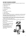
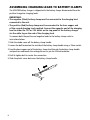
12/24V 70A MANUAL
WORKSHOP
BATTERY CHARGER
P/No. HDBC90
IMPORTANT SAFETY INFORMATION
Please read this manual thoroughly before use and store in a safe place for future reference.
WARNING
• Explosive gases. Prevent flames and sparks. Provide adequate ventilation during charging.
• Before charging, read the instructions.
• For indoor use. Do not expose to rain.
• For charging lead acid batteries ONLY (of the size & voltage specified in the
specifications table).
• Always charge the battery on the correct voltage setting. Never set the charger
to a higher voltage than the battery.
• Disconnect the 240V mains supply before making or breaking the connections
to the battery.
• The battery charger must be plugged into an earthed socket-outlet.
• Connection to supply mains is to be in accordance with National wiring rules.
• Do not attempt to charge non-rechargeable batteries.
• Never charge a frozen battery.
• If the AC cord is damaged do not attempt to use. It must be replaced or repaired
by a qualified person.
• Corrosive substances may escape from the battery during charging and damage
delicate surfaces. Store and charge in a suitable area.
• Ensure all vehicle accessories including lights, heaters, appliances etc are turned off
prior to charging.
• This charger is not intended for use by persons (including children) with reduced
physical, sensory or mental capabilities, or lack of experience and knowledge, unless
they have been given supervision or instruction concerning use of the appliance by
a person responsible for their safety.
• Young children should be supervised to ensure that they do not play with the appliance.
2
FEATURES
ENGINE START FUNCTION
Starts vehicle’s with a flat battery after a controlled 5 minute charge.
CHARGE METER
Clearly displays the rate of charge in Amps to ensure an accurate and thorough charge.
ADJUSTABLE OUTPUT
Adjust the rate of charge to best suit different battery sizes.
RAPID CHARGE
Increases charge rate for a short powerful charge.
MULTI VOLTAGE OPERATION
Suitable for charging 12V & 24V batteries.
0–60MIN TIMER
Automatically turns the battery charger off after a set time when charging your battery
in Rapid Charge mode.
POLARITY PROTECTION
Fuse protection prevents damage to the charger in the event of reverse polarity and
short circuit.
3
SPECIFICATIONS
P/No.
TYPE
INPUT
OUTPUT
ENGINE START
MINIMUM START
VOLTAGE
BACK DRAIN
APPROVALS
4
HDBC90
Manual
240V, 50Hz, 2000W
9.0A at 12V (setting 1)
23.0A at 12V (setting 2)
60.0A at 12V (setting 3)
70.0A at 12V (rapid charge)
3 sec on, 2 min off
12V24V
360A at 6V
360A at 12V
0.0V
12V24V
5.5mA
11.6mA
Electrical Safety, EMC
11.0A at 24V (setting 1)
27.0A at 24V (setting 2)
60.0A at 24V (setting 3)
70.0A at 24V (rapid charge)
BATTERY CHARGER ASSEMBLY
Your HDBC90 is shipped with the following parts which require assembly to the main
body of the battery charger unit:
• 1 x Battery Charger Handle
• 4 x 50mm Screws
• 1 x Bottom Stabiliser Stop
• 2 x 50mm Self Tapping Screws
• 2 x Trolley Wheels
• Wheel Axle
• 2 x Black Voltage Terminal Caps
• 2 x 35mm Washers
• 2 x Wheel Locking Rings.
1. Place the main body of the battery charger in an upright position, install the top handle
of the battery charger using the 4 x 50mm screws as per the below illustration. Use a
Phillips head screw driver to tighten all 4 screws.
2. Lay the main body of the battery charger down flat and fit the stabiliser stop to the
bottom of the battery charger using the 2 x 50mm self tapping screws provided. Use
a Phillips head screw driver to tighten screws.
3. Place the wheel axle provided through the bottom of the battery charger as per the
below illustration.
4. Place the 2 x 35mm washers on either
end of the axle.
5. Fit the 2 trolley wheels to either end of
the axle and secure with the 2 x wheel
locking ring’s provided.
6. Screw the 2 x black voltage terminal
caps provided to both the 12V &
24V outlets on the top panel of the
battery charger.
5
ASSEMBLING CHARGING LEADS TO BATTERY CLAMPS
The HDBC90 battery charger is shipped with the battery clamps disconnected from the
positive & negative charging leads.
IMPORTANT:
•The negative (Black) battery clamp must be connected to the charging lead
connected to the unit.
•The positive (Red) battery clamp must be connected to the bare copper end
of the second charging lead supplied. Connect the opposite end of the charging
lead to either the 12V or 24V outlet on the top panel of the battery charger
via the cable lug on the end of the charging lead.
To connect both the positive and negative leads to the battery clamps refer to
instructions below:
1.Slide the rubber cover off the battery clamp handle.
2.Loosen the bolt located on the outside of the battery clamp handle using a 10mm socket.
3.Feed the bear copper end of the battery clamp lead through the battery clamp handle
and position underneath the rectangular nut as per the illustration below.
4.Refit & tighten bolt to create firm connection.
5.Slide the plastic cover back over the battery clamp handle.
6
CHARGING INSTRUCTIONS
STEP 1 – CHECK THE ELECTROLYTE LEVEL
Prior to charging the battery, remove the vent caps and check the electrolyte level. (Not
required on sealed & maintenance free batteries). The electrolyte should be 6mm (1/4”)
above the battery’s plates.
If low, top up the electrolyte with distilled water to the correct level and refit the vent
caps.
STEP 2A – CONNECTION OUT OF VEHICLE
Connect the RED lead (battery clip) from the charger to the Positive (+) battery post.
Connect the BLACK lead (battery clip) from the charger to the Negative (-) battery post.
CONNECTION OUT OF VEHICLE
POWER ON
A
10
WORKSHOP 7000
60
3
FUSE 2 x 100A
50
12/24 VOLT 70 AMP BATTERY CHARGER WITH ENGINE START
20
24V
30
40
12V
WORKSHOP 7000
12/24 VOLT 70 AMP BATTERY CHARGER WITH ENGINE START
STEP 2B – CONNECTION IN VEHICLE
Determine if the vehicle is Positively (+) or Negatively (-) earthed. Negatively earthed
vehicles have a cable (usually black) from the Negative battery terminal to the vehicle’s
chassis.
POWER ON
POWER ON
60
10
WORKSHOP 7000
3
A
3
A
FUSE 2 x 100A
24V
ENGINE START
12/24 VOLT 70 AMP BATTERY CHARGER WITH
40
50
30
WORKSHOP 7000
20 10
12V
60 50
12/24 VOLT 70 AMP BATTERY CHARGER WITH ENGINE START
FUSE 2 x 100A
20
24V
30
40
12V
NEGATIVELY EARTHED (MOST VEHICLES)
WORKSHOP 7000
WORKSHOP 7000
Connect the RED lead (battery clip) from the charger to the Positive (+) battery terminal.
12/24 VOLT 70 AMP BATTERY CHARGER WITH ENGINE START
12/24 VOLT 70 AMP BATTERY CHARGER WITH ENGINE START
Connect the BLACK lead (battery clip) from the charger to the vehicle’s chassis away
from the fuel line or moving parts.
CONNECTION IN VEHICLE (NEGATIVELY EARTHED)
POWER ON
A
WORKSHOP 7000
60
3
FUSE 2 x 100A
10
POWER ON
50
12/24 VOLT 70 AMP BATTERY CHARGER WITH ENGINE START
20
40
60
30
24V
10
WORKSHOP 7000
3
A
12V
FUSE 2 x 100A
50
12/24 VOLT 70 AMP BATTERY CHARGER WITH ENGINE START
20
24V
30
40
12V
WORKSHOP 7000
12/24 VOLT 70 AMP BATTERY CHARGER WITH ENGINE START
WORKSHOP 7000
12/24 VOLT 70 AMP BATTERY CHARGER WITH ENGINE START
7
POWER ON
A
10
WORKSHOP 7000
60
3
FUSE 2 x 100A
50
12/24 VOLT 70 AMP BATTERY CHARGER WITH ENGINE START
20
40
24V
30
12V
POWER ON
A
10
WORKSHOP 7000
60
3
FUSE 2 x 100A
50
12/24 VOLT 70 AMP BATTERY CHARGER WITH ENGINE START
20
24V
30
40
12V
POSITIVELY EARTHED
Connect the BLACK lead (battery clip)WORKSHOP
from 7000
the charger to the Negative (-) battery terminal.
12/24 VOLT 70 AMP BATTERY CHARGER WITH ENGINE START
Connect the RED lead (battery clip) from the charger to the vehicle’s chassis away from the
fuel line or moving parts.
CONNECTION IN VEHICLE (POSITIVELY EARTHED)
POWER ON
A
10
WORKSHOP 7000
60
3
FUSE 2 x 100A
50
12/24 VOLT 70 AMP BATTERY CHARGER WITH ENGINE START
20
40
24V
30
12V
WORKSHOP 7000
12/24 VOLT 70 AMP BATTERY CHARGER WITH ENGINE START
STEP 3 – CONNECT TO 240V MAINS POWER
Ensure ‘CHARGE RATE’ dial is turned to OFF & connect the battery charger to 240V
mains power.
STEP 4 – SET BATTERY VOLTAGE
Set the voltage of the battery charger by removing the black terminal cap from either the
12V or 24V terminal on the top panel of the jumpstarter. Connect the positive battery
cable via the ring terminal to the appropriate 12V or 24V outlet. Ensure the battery charger
voltage is set to the same voltage as the battery being charged.
STEP 5 – SET THE CHARGE MODE
NORMAL CHARGE RATE ADJUSTMENT
The normal charge rate can be adjusted by turning the ‘CHARGE RATE’ dial on the top
panel of the unit to setting 1, 2 or 3. The charge rate should be set according to the size
of the battery.
See the recommended charge rates for various battery sizes in the table below:
CHARGE RATE
BATTERY SIZE
Deep Cycle (Ah)
Automotive (CCA) Marine (MCA)
Time (Hours)
Setting 1 (12V)
60–180
380–1080
520–1500
7–24
Setting 1 (24V)
75–220
460–1300
640–1830
7–24
Setting 2 (12V)
160–460
670–2800
1340–3800
7–24
Setting 2 (24V)
190–540
1130–3240
1600–4500
7–24
Setting 3 (12/24V)
420–1200
2500–7200
3500–1000
7–24
8
RAPID CHARGE
Turn the ‘CHARGE RATE’ dial on the top panel of the unit to ‘RAPID CHARGE’ & set the
timer between 0-60min. The Rapid Charge function will provide a 70A charge to your
battery ideal for when a short powerful charge is required.
STEP 6 – CHARGING
During charging, the Charge Meter’s needle will decrease
towards the left. A fully charged battery is indicated by a very
low reading according to the battery’s capacity and condition.
Once this point has been reached, proceed to disconnect the
battery (Refer STEP 7 “DISCONNECTION”).
Important:
Charging will continue until the On/Off switch is turned to OFF.
Charge Meter
The battery and charger must be monitored to ensure the battery is not overcharged.
Once charged, the liquid inside the battery may start to boil. It is recommended to stop
charging when this occurs to prevent damage to the battery.
STEP 7 – DISCONNECTION
Turn the ‘CHARGE RATE’ dial to the ‘OFF’ position and disconnect charger from
the 240V supply.
Battery out of vehicle
Remove the BLACK lead (battery clip) from the battery. Remove the RED lead (battery
clip) from the battery.
Battery in vehicle
Remove the chassis connection. Remove the battery terminal connection.
9
ENGINE START FUNCTION
STEP 1 TO 4 – Follow STEPS 1 to 4 of the charging instructions of this booklet.
STEP 5 – Turn the ‘CHARGE RATE’ dial to the ‘RAPID CHARGE’ function, and set the
‘TIMER’ dial to 5 minutes and allow charger to charge the vehicles battery.
STEP 6 – Once the 5 minute Rapid Charge is complete, turn the ‘CHARGE RATE’
dial to ‘ENGINE START’.
STEP 7 – Turn the vehicle’s ignition key to start the engine.
STEP 8 – If engine fails to start after 3 seconds repeat instruction STEP 5 & 6 before
attempting to start the engine again.
NOTE: Do not repeat this operation more than 5 times.
NOTE: When in engine start mode the HDBC90 uses increased power for a short period
of time. Ensure other appliances connected to that power circuit are turned off to avoid
fuse or circuit breaker overload in the buildings switchboard.
10
PRODUCT OVERVIEW
Positive Battery
Clamp
Negative Battery
Clamp
Trolley Wheels
Bottom Stabiliser Stop
240V Mains Power Cord
Charge Meter
Power On
Indicator
Charge/Engine
Start/Off Switch
Output Fuse
Charge Timer
12V/24V Terminals
11
HOW TO CHANGE OUTPUT FUSE
The battery charger is fitted with 2 x 100A fuses designed to protect the battery
charger against reverse connection & short circuit, the fuse is located on the top panel
of the battery charger.
To replace blown fuses:
1. Disconnect battery charger from 240V mains power.
2. Disconnect battery charger leads from the vehicles battery.
3. Remove fuse cover on the top panel of the unit.
4. Remove and refit fuses (Projecta P/No. HDBCF100A) using a 10mm socket.
5. Refit fuse cover.
12
FREQUENTLY ASKED QUESTIONS
Q.How do I know if the battery is fully charged?
A. The Charge Meter’s needle will decrease towards the left. A fully charged battery is
indicated by a very low reading. Refer to STEP 6 of the charging instructions for an
illustration of the Charge Meter.
Alternatively use a Battery Hydrometer (Projecta Part No. BH100). A reading of 1.250
or more in each cell indicates a fully charged battery.
Q. Why does the Charge Meter indicate a fully charged battery straight away?
A. There are four possible reasons why the Charge Meter may indicate a fully charged
battery straight away.
1. The battery is fully charged.
2. The battery has taken a surface charge.
3. The battery has a faulty cell.
4. The BATTERY VOLTAGE setting on the charger is set lower than the battery voltage.
Q.What is Surface Charge?
A.Batteries unused or left flat for some time build up a resistance to being recharged.
When the charger is first connected, these batteries will take a surface charge, and the
Charge Meter will indicate a fully charged battery within a short while. The battery
however is not fully charged, the charger is voltage sensitive and cannot differentiate
between a surface charge and a fully charged battery. After a few hours the battery
may start to accept some charge but most batteries with this condition will not recover.
Q.What is a Faulty Cell?
A.12 Volt batteries contain 6 cells and one faulty cell is enough to ruin your battery.
If after eight hours of charging your battery is still flat, you should test the cells using
a hydrometer. If one reading is lower than the rest it indicates a faulty cell. It is
pointless to continue charging, as the battery needs replacing.
Q.Can I use the charger as a power supply?
A.No. The HDBC90 cannot be used as a power supply. Do not attempt to connect the
clamps to anything other than a suitable battery.
13
Q.What are Volts and Amps?
VOLTS
The term voltage refers to the electrical force or electric potential to do work between
two terminals or a good analogy is water pressure in a pipe. For example a battery has
12 Volts between the positive and negative terminals, or a 6 Volt battery has 6 Volts
between the positive and negative terminals.
AMPS
The term AMPS is the unit of measure used for current. This can be described as the
flow of electric charge in a circuit. Again if you use the water analogy this would refer
to how much water is flowing through the pipe. For example if the current is reading
12 Amps then this is the amount of energy going into the battery.
14
NOTES:
15
WARRANTY STATEMENT
Brown & Watson International Pty Ltd (“BWI”) of 1500 Ferntree Gully Road, Knoxfield,
Vic., telephone (03) 9730 6000, fax (03) 9730 6050, warrants that all products described
in its current catalogue will under normal use and service be free of failures in material
and workmanship for a period of one (1) year from the date of the original purchase by the
customer as marked on the invoice. This warranty does not cover ordinary wear and tear,
abuse, alteration of products or damage caused by the purchaser.
To make a warranty claim the consumer must deliver the product at their cost to the
original place of purchase or to any other place which may be nominated by either BWI or
the retailer from where the product was bought in order that the warranty assessment may
be performed. The consumer must also deliver the original invoice evidencing the date and
place of purchase together with an explanation in writing as to the nature of the claim.
In the event that the claim is determined to be for a minor failure of the product then
BWI reserves the right to repair or replace it at its discretion. In the event that a major
failure is determined the consumer will be entitled to a replacement or a refund as well as
compensation for any other reasonably foreseeable loss or damage.
This warranty is in addition to any other rights or remedies that the consumer may have
under State or Federal legislation.
IMPORTANT NOTE
Our goods come with guarantees that cannot be excluded under the Australian Consumer
Law. You are entitled to a replacement or refund for a major failure and compensation for
any other reasonably foreseeable loss or damage. You are also entitled to have the goods
repaired or replaced if the goods fail to be of acceptable quality and the failure does not
amount to a major failure.
Distributed by
AUSTRALIA
Brown & Watson International Pty Ltd
Knoxfield, Victoria 3180
Telephone (03) 9730 6000
Facsimile (03) 9730 6050
National Toll Free 1800 113 443
NEW ZEALAND
Narva New Zealand Ltd
22–24 Olive Road
PO Box 12556 Penrose
Auckland, New Zealand
Telephone (09) 525 4575
Facsimile (09) 579 1192
IS166
Issue 2 1.6.12