1
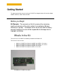
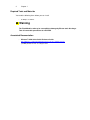
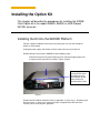
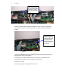
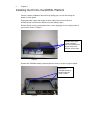
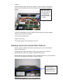
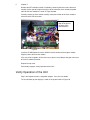
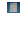
Winterm™ Model 9450XE, 9455XL and J400, Product
941GXL
512MB Flash Option Kit
Installation Guide
Winterm™ Model 9450XE, 9455XL and
J400, Product 941GXL
Flash Option Kit
Installation Guide
Issue: 072205
Wyse Technology Inc.
3471 North First Street
San Jose, CA 95134-1803
Copyright Notice
© 2005 Wyse Technology Inc. All rights reserved.
This manual is copyrighted. You may not reproduce, transmit, transcribe, store in a retrieval
system, or translate into any language or computer language, in any form or by any means,
electronic, mechanical, magnetic, optical, chemical, manual or otherwise, any part of this
publication without express written permission.
End User License Agreement (“License”)
A printed copy of the Wyse Technology End User License Agreement is included in the original
shipping box and provided for your reference only. The License at http://www.wyse.com/license
as of the purchase date is the controlling licensing agreement. By copying, using, or installing the
software or the product, you agree to be bound by those terms.
Trademarks
Wyse, WY, and WyseWorks are registered trademarks, and the Wyse logo, Winterm logo,
Wyse, and Winterm are trademarks of Wyse Technology Inc.
Rapport is a registered trademark of Rapport Technologies Inc., a division of Wyse Technology.
ICA is a registered trademark and MetaFrame is a trademark of Citrix Systems Inc.
Microsoft, Windows, Windows CE, Windows NT, Windows XP, and Windows Terminal Server are
registered trademarks of Microsoft Corporation.
All other products are trademarks and/or registered trademarks of their respective companies.
Specifications subject to change without notice.
Patents
The Wyse product(s) described herein is(are) covered by U.S. Patent No. 5,918,039 and
other patents pending.
Restricted Rights Legend
You acknowledge that the Software is of U.S. origin. You agree to comply with all applicable
international and national laws that apply to the Software, including the U.S. Export
Administration Regulations, as well as end-user, end-use and country destination restrictions
issued by U.S. and other governments. For additional information on exporting the Software, see
http://www.microsoft.com/exporting.
Ordering Information
For availability, pricing, and ordering information in the United States and Canada, call
1-800-GET-WYSE (1-800-438-9973) or visit us at http://www.wyse.com. In all other countries,
contact your sales representative.
FCC Statement
This equipment has been tested and found to comply with the limits for either Class A or
Class B digital devices (refer to "Thin Client Requirements Compliance"), pursuant to Part 15 of
the FCC Rules. These limits are designed to provide reasonable protection against harmful
interference in a residential installation. This equipment generates, uses, and can radiate radio
frequency energy and, if not installed and used in accordance with the instructions, may cause
harmful interference to radio communications. However, there is no guarantee that interference
will not occur in a particular installation. If this equipment does cause harmful interference to radio
or television reception, which can be determined by turning the equipment off and on, the user is
encouraged to try to correct the interference by one or more of the following measures:
• Reorient or relocate the receiving antenna.
• Increase the separation between the equipment and the receiver.
• Connect the equipment into an outlet on a circuit different from that to which the receiver is
connected.
• Consult the dealer or an experienced radio/TV technician for help.
Caution
Changes or modifications not covered in this manual must be approved in writing by the
manufacturer’s Regulatory Engineering department. Changes or modifications made without
written approval may void the user’s authority to operate the equipment.
Thin Client Requirements Compliance
FCC Compliance
The Models 9450XE, 9455XL, and Model J400, Product 941GXL, Thin Clients meet Class B
requirements.
IEC/EN Compliance
The Models 9450XE, 9455XL, and Model J400, Product 941GXL, Thin Clients meet Class B
requirements.
Canadian DOC Notices
Refer to the previous section, "Thin Client Requirements Compliance," to find out to which
thin client model each of the statements below refers.
Class A
This digital apparatus does not exceed the Class A limits for radio noise emissions from digital
apparatus set out in the Radio Interference Regulations of the Canadian Department of
Communications.
Le présent appareil numérique n’émet pas de bruits radioélectriques dépassant les limites
applicables aux appareils numériques de la classe A prescrites dans le Réglement sur le
brouillage radioélectrique édicté par le Ministère des Communications du Canada.
Class B
This digital apparatus does not exceed the Class B limits for radio noise emissions from digital
apparatus set out in the Radio Interference Regulations of the Canadian Department of
Communications.
Le présent appareil numérique n’émet pas de bruits radioélectriques dépassant les limites
applicables aux appareils numériques de la classe B prescrites dans le Réglement sur le
brouillage radioélectrique édicté par le Ministère des Communications du Canada.
IEC/EN Notice
These products conform to the requirements of IEC950 and EN60950.
These products conform to requirements of EN55022 for Class A equipment or EN55022
for Class B equipment (refer to "Thin Client Requirements Compliance").
Cable Notice
The use of shielded I/O cables is required when connecting this equipment to any and all
optional, peripheral or host devices. Failure to do so may cause interference and violate
FCC and international regulations for electromagnetic interference.
Noise Suppressor
A noise suppressor (ferrite bead) must be installed on the network cable of your thin client.
This installation is necessary to maintain compliance with U.S. FCC B limits and European
CISPR B EN55022 Class B limits. The noise suppressor is supplied by the manufacturer
and is packed in your thin client’s shipping carton.
Device Power Supply
Caution
Replace power supply with the same or equivalent type as recommended by
the manufacturer.
Model 9450XE and 9455XL Thin Clients
For use with External Power Supply Li Shin Model LSE9802A1255 or certified equivalent
model supplied by the manufacturer, rated 12V/4.58A.
Model 9650XE Thin Client
For use with External Power Supply Li Shin Model LSE0219B1280 or certified equivalent
model supplied by the manufacturer, rated +12V/6.67A.
Model J400, Product 941GXL Thin Client
For use with External Power Supply Li Shin Model LSE9802A1255 or certified equivalent
model supplied by the manufacturer, rated +12V/4.58A.
Battery Information
The 9450XE, 9455XL, and Model J400, Product 941GXL Thin Clients
contain a replaceable battery.
Warning
There is a risk of explosion if the battery is replaced by an incorrect type.
Always dispose of used batteries according to the instructions accompanying
the battery.
Contents
Getting Started 1
Before You Begin
1
What’s In the Kit
1
Required Tools and Materials
Associated Documentation
3
3
Installing the Option Kit 2
Install the kit in the 9450XE
Install the kit in the 9455XL
Install the kit in the 941GXL
Verify Operation of the Unit
1
3
4
5
Getting Started
This document describes how to install your 512 MB Flash Upgrade Option Kit into either Model
9450XE, 9455XL or J400, Product 941GXL
Before you Begin
Kit Warranty: The warranty on this kit assumes the remaining
months of warranty of the unit in which it is installed or 90 days
whichever is greater. Installation of this kit will not void the factory
warranty however the user will be responsible for damage due to
improper installation.
What’s In the Kit
The kit consists of a 512MB Flash Module preloaded with Windows XP
The kit comes in four versions
920223-21 512MB Flash Option for 9450XE and 9455XL, US versions
920223-22 512MB Flash Option for 9450XE and 9455XL, Int’l versions
920223-23 512MB Flash Option for 941GXL, US versions
920223-24 512MB Flash Option for 945XL, Int’l versions
P/N 920223-21 512MB Flash Option
2
Chapter 1
Required Tools and Materials
You need the following items before you can install.
o
#1 Phillips screwdriver
Warning
The Flash Module card may be susceptible to damage by Electro-static discharge.
Take all reasonable precautions to avoid ESD.
Associated Documentation
o
Winterm™ 9000 Series Quick Reference Guide
http://www.wyse.com/products/winterm/reference/9series/883808-01C.pdf
(3.62MB) 883808-01 Rev. C © August 2004
Installing the Option Kit
This chapter will describe the procedures for installing the 512MB
Flash Option kit in the model 9450XE, 9455XL or J400 Product
941GXL terminals.
Installing the Kit into the 9450XE Platform
Perform a proper shutdown of the terminal by ending your session and clicking the
buttons as they appear.
Unplug the power supply and remove all of the cables from the rear of the unit.
Remove the top cover from the 9450XE using the following steps:
Remove the top cover by pinching the top cover clamp and applying pressure
using the palm of your hand as shown in Figure 1 below.
Pinch the top cover
clamp with one hand
and apply pressure
with the palm of your
other hand in the
direction of the arrow.
Figure 1
Remove the IDE module retention bracket, if applicable, in Figure 2 or 3. Bracket may be
plastic or metal. In some cases a drop of hot glue is applied to the IDE connector.
Carefully cut this drop of glue if applicable.
2
Chapter 2
Remove the plastic
or metal IDE module
retention bracket by
removing the Philips
screw.
Figure 2
Figure 3
Remove the power cable from the flash module as shown in Figure 4 and carefully
remove the flash module from the socket. Note the connector where the module is
located.
Remove the power
cable connector and
carefully remove the
flash module from
the IDE connector
noting the location of
the module.
Figure 4
Install the 512MB Option kit into the 9450XE into the location of the original module.
Plug the power cable into the module.
Reinstall the IDE module retention bracket. This bracket is installed to prevent
movement during shipping. You may leave this out if desired.
Replace the top cover.
Proceed to paragraph “Verify Operation of the Unit”.
3
Chapter 2
Installing the Kit into the 9455XL Platform
Perform a proper shutdown of the terminal by ending your session and clicking the
buttons as they appear.
Unplug the power supply and remove all of the cables from the rear of the unit.
Remove the top cover from the 9455XL using the following steps:
Remove the top cover by removing the three screws applying pressure using the palm of
your hand as shown in Figure 5.
Remove these three
screws and apply
pressure with the palm
of your hand in the
direction of the arrow.
Figure 5
Remove the CDROM bracket by removing the two screws as shown in Figure 6 below.
Remove the
CDROM bracket by
removing the two
Philips screws.
Figure 6
4
Chapter 2
Remove the power cable from the flash module as shown in Figure 7 and carefully
remove the flash module from the socket. Note the connector where the module is
located.
Remove the power
cable connector and
carefully remove the
flash module from
the IDE connector
noting the location of
the module.
Figure 7
Install the 512MB Option kit into the 9455XL into the location of the original module.
Plug the power cable into the module.
Reinstall the CDROM bracket.
Replace the top cover
Proceed to paragraph “Verify Operation of the Unit”.
Installing the Kit into the 941GXL Platform
Perform a proper shutdown of the terminal by ending your session and clicking the
buttons as they appear.
Unplug the power supply and remove all of the cables from the rear of the unit.
Remove the top cover from the 941GXL using the following steps:
Remove the top cover by removing the single screw applying pressure, using the palm of
your hand, in the direction of the arrow as shown in Figure 8
Remove the single
screw and apply
pressure with the palm
of your hand in the
direction of the arrow.
Figure 8
5
Chapter 2
Remove the IDE retention bracket if installed by removing the two screws, otherwise
carefully cut the spot of hot glue at the base of the connector, then remove the power
cable for the flash module as shown in Figure 9 below.
Carefully remove the flash module carefully noting the location of the flash module in
reference to the IDE connectors.
Carefully cut the
drop of hot glue at
the base of the
connector then
Figure 9
Install the 512MB Option kit into the 941GXL into the location of the original module.
Plug the power cable into the module.
If the unit will be shipped it will be necessary to place a small drop of hot glue at the base
of the flash module connector.
Replace the top cover
Proceed to paragraph “Verify Operation of the Unit”.
Verify Operation of the Unit
Plug in the keyboard, mouse, and power adaptor. Press the start button.
The unit will boot up and display as shown in the picture below in Figure 10.
6
Chapter 2
Figure 10
Click on the “Start” and “About” links and the display will be as shown as below in Figure
11.
Figure 11
The display will be as shown in Figure 12 below. Verify that the MAC address and Serial
Number as displayed match the serial number and MAC address on the unit.
Figure 12
The unit is ready for operation and setup by the Administrator.