1
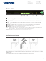
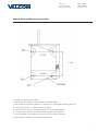
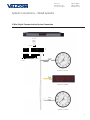
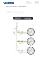
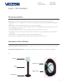
Installation Manual V4.3
V-WMCA Master Clock
V-GPSA
V-GPS-TX
Valcom, Inc.
5614 Hollins Road
Roanoke, VA 24019
540-563-2000 P.
540-362-9800 F.
www.valcom.com
Valcom, Inc.
5614 Hollins Road
Roanoke, VA 24019
540-563-2000 P.
540-362-9800 F.
www.valcom.com
V-WMCA Master Clock
V-GPSA
V-GPS-TX
Table of Contents
Table of Contents—2
Table of Contents—3
Wall Mount Installation —4
Installing the Master Clock with the Line Cord Receptacle—5
AC Power Wiring using 14 AWG Romex Cable—5
Rear View of Unit—6
Installing the Remote Antenna—6
Remote Antenna Mounting Instructions—7
2 Wire Digital Communication System Connection—8
Sync-Wire Communication System Connection—9
59 Minute Correction—10
58 Minute Corrections 1–4—10
National Time/Rauland—11
Rauland Digital—11
Dukane Digital—12
Once a Day Pulse—12
Fire Alarm Interface Installation—13
Patch Cable Installation—13
GPS Antenna Installation—14
Setting Master Clock to GPS Mode—14
Setting the Time from the LED Display—15
Programming the Master Clock—15
Sync-Wire Communication – Protocol Definitions—21
Error Codes on LED Display—22
Accessing the Web Interface (when connected via DHCP)—23
Accessing the Web Interface (when using a static IP)—23
Accessing the Web Interface (when using a crossover cable)—23
Log In—24
Date/Time—25
System Settings—26
DST—27
Synchronization—28
IP—29
*manuals may change without prior notice
2
Valcom, Inc.
5614 Hollins Road
Roanoke, VA 24019
540-563-2000 P.
540-362-9800 F.
www.valcom.com
V-WMCA Master Clock
V-GPSA
V-GPS-TX
Table of Contents
NTP Servers—30
IP Status—31
Clock Features—32
Database Maintenance—33
Frequently Asked Questions—34
Troubleshooting—35
Compliances—36
3
Valcom, Inc.
5614 Hollins Road
Roanoke, VA 24019
540-563-2000 P.
540-362-9800 F.
www.valcom.com
Wall Mount Installation
Fig 1
1. Place the supplied template on the wall where the master clock is being mounted.
2. Mark the center point of the top right hole. Drill the hole and install the supplied anchor from the mounting kit.
3. Install the screw into the anchor and hang the template from the top right hole.
4. Using a level and the LINE on the supplied template, mark the center of the three remaining holes.
5. Remove the template and drill out the three remaining holes and insert the anchors.
6. Insert the two top screws into the anchors, leaving 1/8” of thread exposed. Unscrew the bottom wiring cover on the master clock.
7. Line up the top keyholes on the back of the master clock with the two top screws. Slide the master clock into the keyholes and then lock it into
place.
8. Insert the two remaining bottom screws.
9. Screw the wiring cover back into its original position.
4
Valcom, Inc.
5614 Hollins Road
Roanoke, VA 24019
540-563-2000 P.
540-362-9800 F.
www.valcom.com
Before You Get Started
Installing the Master Clock with the Line Cord Receptacle
Remainder of cord not shown
Caution! Do not plug in the power cord until the following steps are completed.
*220-240 VAC
Disconnect
1. The square knockout on the wiring chassis must be removed.
2. The Heyco Bushing must be attached to the power cord as shown. Use pliers to push both halves of the bushing together while they lock.
3. Put the wires through the knockout and push the bushing into the metal until it locks tightly into place. The word Heyco on the bushing faces
up.
4. Put each wire into the supplied connector and tighten the screws. The wiring label located on the chassis will show where to connect the
wires.
AC Power Wiring using 14 AWG Romex Cable
*Note: For CE Compliant installation, use minimum 0.75mm² cable or approved grounded cordset
Caution! The AC Power Source must be turned OFF.
1. Remove a round knockout on the wiring chassis, preferably one near the AC Input Connector.
2. Install a standard ½” Romex Bushing and tighten in place.
3. Pass the Romex Cable through the Bushing and clamp in place. Do Not over tighten the screws.
4. Strip back the outside cable sheathing to expose the White, Black and Ground wires.
5. Strip back the insulation on the White and Black wire ¼”.
6. Put each wire into the supplied connector and tighten the screws. The wiring label located on the wiring chassis indicates where to connect
the wires.
5
Valcom, Inc.
5614 Hollins Road
Roanoke, VA 24019
540-563-2000 P.
540-362-9800 F.
www.valcom.com
Rear View of Unit
|
|
q
q Clock 1 & 2 Sync-Wire Outputs |
|
w
|
|
e
|
|
r
|
|
t
|
|
y
This terminal block is where connections would be landed for Clock 1 and Clock 2 sync-wire
communication relay outputs.
w RS485 Input/Output This terminal block is where connections would be landed for RS485 communication to and from other Valcom
systems.
e Inputs This terminal block is where connections would be landed to use the master clock as a slave clock when being controlled by
another system.
r Ethernet This RJ45 jack is used for connecting the master clock to a network for programming and/or timekeeping capabilities.
t GPS Connector This GPS connector is where the antenna for the GPS gets mounted to (GPS option only).
y Power Input This power outlet is used to power up the master clock.
NOTE: This device contains a lithium battery. Replace Battery With Varta, Part No. CR2032 Only. Use Of Another Battery May Present A Risk Of Fire Or Explosion. Batteries can be obtained and should be installed by the manufacturer.
WARNING: Battery May Explode If Mistreated. Do Not Recharge, Disassemble Or Dispose Of In Fire.
Installing the Remote Antenna
Blue
Green
Yellow
White
Red
Connect the Remote Antenna to the Master Clock using the supplied 25 foot, 5 conductor 18 AWG cable. Use the wiring diagram and colors as shown above.
Strip the insulation back 1/4 inch on each wire. Use a bushing in the wiring chassis to pass the cable through and secure it, then insert wires into the conductor
and tighten the screws.
For all input and output wiring use copper conductors only tightening torque for terminal block screws is 31 to 35 in/oz.
6
Valcom, Inc.
5614 Hollins Road
Roanoke, VA 24019
540-563-2000 P.
540-362-9800 F.
www.valcom.com
Remote Antenna Mounting Instructions
1.
2.
3.
4.
5.
6.
7.
8.
Remove the cover of the wiring panel.
Mark the four drilling points on the wall based on the drawing above.
Drill the holes for the anchors supplied in the mounting kit at the designated markings from step 1.
Install the four anchors in the holes that were just drilled.
Install the first two screws in the top holes leaving 1/8” of the thread exposed.
Line up the top key slots over the screws and lock the master clock into place.
Install the bottom screws through the wiring access panel and tighten into place.
After all wiring is complete, re-install the wiring panel cover.
7
Valcom, Inc.
5614 Hollins Road
Roanoke, VA 24019
540-563-2000 P.
540-362-9800 F.
www.valcom.com
System Connections – Wired Systems
2 Wire Digital Communication System Connection
18 19
19 18
DATA IN
V-C6124P
24 volt outputs
+
-
+ -
+
V-C6124P and the V-CCU
are ordered as a V-VCU
V-CCU
-
24 VDC IN
+
-
+ -
+
-
2 W ire Digital
Output to Clocks
*V-C6124P and the V-CCU are ordered as
a V-VCU
White
Black
V-A2412 or V-A2416
V-D2425 or V-D2440
110V
(EU 240V)
White
Black
V-A2412 or V-A2416
8
Valcom, Inc.
5614 Hollins Road
Roanoke, VA 24019
540-563-2000 P.
540-362-9800 F.
www.valcom.com
System Connections – Wired Systems
Sync-Wire Communication System Connection
8 Amp Contact Rating
9
Valcom, Inc.
5614 Hollins Road
Roanoke, VA 24019
540-563-2000 P.
540-362-9800 F.
www.valcom.com
Inputs – Sync-Wire Inputs Installation
59 Minute Correction
12
N.O.
15
17
24VAC Hot
8
24VAC Interface
24VAC Neutral
17
110VAC Neutral
7
110VAC Interface
(EU 240VAC)
16
17
110VAC Hot
Dry Contact Closure
COM
58 Minute Corrections 1–4
N.O.
12
16
17
15
17
24VAC Hot
8
24VAC Neutral
17
24VAC Interface
110VAC Hot
7
110VAC Interface
(EU 240VAC)
110VAC Neutral
Dry Contact Closure
COM
10
Valcom, Inc.
5614 Hollins Road
Roanoke, VA 24019
540-563-2000 P.
540-362-9800 F.
www.valcom.com
Inputs – Sync-Wire Inputs Installation
National Time/Rauland
Dry Contact Closure
110VAC Interface
(EU 240VAC)
24VAC Interface
Rauland Digital
Output
17
8
24
7
23
22
Dig Out
11
+5V Out
Input
11
Valcom, Inc.
5614 Hollins Road
Roanoke, VA 24019
540-563-2000 P.
540-362-9800 F.
www.valcom.com
Inputs – Sync-Wire Inputs Installation
Dukane Digital
Once a Day Pulse
Dry Contact Closure
12
Valcom, Inc.
5614 Hollins Road
Roanoke, VA 24019
540-563-2000 P.
540-362-9800 F.
www.valcom.com
Fire Alarm Interface Installation / Patch Cable Installation
Fire Alarm Interface Installation
The Fire Alarm Interface allows a relay closure to be connected to the master clock that allows the user to interface the existing fire alarm with the
Valcom digital clocks.
7
10
8
9
N.O.
COM
When a relay closure occurs on pins 8 and 9, “FirE” will display on the digital slave clocks connected using RS485 or two wire digital
communication.
Patch Cable Installation
Wall Jack to
Network
Fig 1.1
1) Connect a patch cable to the RJ45 port on the master clock as shown in Fig 1.1.
2) Connect the other end of the patch cable to an Ethernet jack connected to the network.
13
Valcom, Inc.
5614 Hollins Road
Roanoke, VA 24019
540-563-2000 P.
540-362-9800 F.
www.valcom.com
Inputs – GPS Installation
GPS Antenna Installation
Supplied by Valcom: GPS Dome, 75’ length of RG58 cabling (optional 150’ length of RG59 cabling upon request) (refer to Figure 1.1)
Not supplied by Valcom: Steel or PVC piping with 1”-14” thread or 3/4” pipe thread, teflon tape, mounting plate and hardware for piping (refer to
Figure 1.1)
*NOTE: Placement of antenna and height of piping needs to be on the rooftop of the building
1) Route cabling from the room in which the master clock will be located to the roof of the building, allowing the GPS dome (refer to Figure 1.1) to
have a full 180 degrees view of the sky
2) Run cabling through piping and attach the end of the cabling to the bottom of the GPS dome via TNC connection.
3) Screw GPS dome onto the top of the piping. Be careful not to twist the cable. Use teflon tape on the pipe threads to tighten seal and prevent
water damage.
4) Mount piping to the roof of the building with mounting plate and hardwear supplied by the user.
5) Connect the RG58 or 59 cabling to the GPS input located on the back of the master clock via SMA connection.
Setting Master Clock to GPS Mode
Programming through the V-WMCA push buttons - Refer to page 19 for setting your master clock’s time source to GPS from the LCD display.
Programming through the Web Interface - Refer to page 28 for setting your master clock’s time source to GPS from the web interface.
Fig 1.1
GPS Dome
TNC Connection
Piping
SMA Connection
Mounting Plate
14
Valcom, Inc.
5614 Hollins Road
Roanoke, VA 24019
540-563-2000 P.
540-362-9800 F.
www.valcom.com
User Level Programming
Setting the Time from the LED Display
To set the time, press the top button to change the hour and/or the bottom button the set the minute.
See Fig 2.1.
Fig 2.1
Programming the Master Clock
To enter programming mode, press both the top and bottom button together simultaneously. The top button advances through the options while the
bottom button changes the option.
Option 1 - Set Year:
Use the bottom button to scroll from “10-99” on the display and set
the year.
Option 2 - Set Month:
Use the bottom button to scroll between “01-12”.
15
Valcom, Inc.
5614 Hollins Road
Roanoke, VA 24019
540-563-2000 P.
540-362-9800 F.
www.valcom.com
Option 3 - Set Day:
Use the bottom button to scroll between “01-31”.
Option 10 - Technical Mode:
If technical mode is desired, press the bottom button until “08” is
reached. Setting option 10 to “08” will allow the user access to options
11-13 when the top button is pressed. Any other value will go directly
to option “20” when the top button is pressed.
Option 11 - RS485 Data Rate:
Press the bottom button to scroll between “01-12”.
01 - Data is transmitted every second
07 - Data is transmitted every 2 minutes
02 - Data is transmitted every 5 seconds
08 - Data is transmitted every 5 minutes
03 - Data is transmitted every 10 seconds
09 - Data is transmitted every 10 minutes
04 - Data is transmitted every 15 seconds
10 - Data is transmitted every 15 minutes
05 - Data is transmitted every 30 seconds
11 - Data is transmitted every 30 minutes
06 - Data is transmitted every minute
12 - Data is transmitted every hour
Option 12 - Daylight Savings Time:
Press the bottom button to scroll between “d” or “E”.
“d” will disable this option.
“E” will enable this option.
Option 13 - 12/24 Hour Mode:
Press the bottom button to scroll between “12” and “24”.
16
Valcom, Inc.
5614 Hollins Road
Roanoke, VA 24019
540-563-2000 P.
540-362-9800 F.
www.valcom.com
Option 20 - Programming the Clock #1 Circuit:
Press the bottom button to scroll through “1”, “2”, “3”, “4”, “5”,
“6”, “7”, “8” & “9”. Please refer to relay selection mode on page 21.
Option 21 - Once a Day Pulse - Set Hour:
This option is only available if “8” is selected in option 20 for once a
day pulse. Press the bottom button to scroll through “00-23”.
Option 22 - Once a Day Pulse - Set Minutes:
This option is only available if “8” is selected in option 20 for once a
day pulse. Press the bottom button to scroll through “00-59”.
Option 23 - Once a Day Pulse - Set Seconds:
This option is only available if “8” is selected in option 20 for once a
day pulse. Press the bottom button to scroll through “00-59”.
Option 24 - Once a Day Pulse - Set Duration (in seconds):
This option is only available if “8” is selected in option 25 for once a
day pulse. Press the bottom button to scroll through “00-99”.
17
Valcom, Inc.
5614 Hollins Road
Roanoke, VA 24019
540-563-2000 P.
540-362-9800 F.
www.valcom.com
Option 25 - Programming the Clock #2 Circuit:
Press the bottom button to scroll through “1”, “2”, “3”, “4”, “5”,
“6”, “7”, “8” & “9”. Please refer to relay selection mode on page 21.
Option 26 - Once a Day Pulse - Set Hour:
This option is only available if “8” is selected in option 25 for once a
day pulse. Press the bottom button to scroll through “00-23”.
Option 27 - Once a Day Pulse - Set Minutes:
This option is only available if “8” is selected in option 25 for once a
day pulse. Press the bottom button to scroll through “00-59”.
Option 28 - Once a Day Pulse - Set Seconds:
This option is only available if “8” is selected in option 25 for once a
day pulse. Press the bottom button to scroll through “00-59”.
Option 29 - Once a Day Pulse - Set Duration (in seconds):
This option is only available if “8” is selected in option 25 for once a
day pulse. Press the bottom button to scroll through “00-99”.
18
Valcom, Inc.
5614 Hollins Road
Roanoke, VA 24019
540-563-2000 P.
540-362-9800 F.
www.valcom.com
Option 30 - Set the Primary Input:
Press the bottom button to scroll between “1-13” to select the input.
00 - Real Time Clock
01 - SNTP 02 - 59 Minute Correction
03 - 58 Minute Correction (1)
04 - 58 Minute Correction (2)
05 - 58 Minute Correction (3)
06 - 58 Minute Correction (4)
07 - National Time/Rauland
08 - Dukane
09 - Rauland Digital
10 - Wireless Repeater
11 - Once a Day Pulse*
12 - GPS
13 - RS485
* - Selecting this allows access to options 34-36
Option 31 - Set the Secondary Input:
This option is only available if “8” is selected in option 25 for once a
day pulse. Press the bottom button to scroll through “00-23”.
00 - Real Time Clock
01 - SNTP 02 - 59 Minute Correction
03 - 58 Minute Correction (1)
04 - 58 Minute Correction (2)
05 - 58 Minute Correction (3)
06 - 58 Minute Correction (4)
07 - National Time/Rauland
08 - Dukane
09 - Rauland Digital
10 - Wireless Repeater
11 - Once a Day Pulse*
12 - GPS
13 - RS485
* - Selecting this allows access to options 34-36
Option 32 - Setting the Time Zone Offset:
Press the bottom button to scroll through “-12 to 12”. See Fig 4.1 on
page 26 for examples of common offsets.
Option 33 - Set the Bias Seconds + 7500 seconds to - 999 seconds:
This option allows the user to set the bias seconds which allows the
user to adjust the input’s time plus 7500 seconds or minus 999 seconds.
Press the bottom button to scroll through “0000 - 7500”.
Option 34 - Once a Day Pulse Input- Set Hour
This option is only available when option 30 or 31 is set to 11. Press the
bottom button to scroll through “00-23”.
19
Valcom, Inc.
5614 Hollins Road
Roanoke, VA 24019
540-563-2000 P.
540-362-9800 F.
www.valcom.com
Option 35 - Once a Day Pulse Input - Set Minutes
This option is only available when option 30 or 31 is set to 11. Press the
bottom button to scroll through “00-59”.
Option 36 - Once a Day Pulse - Set Seconds
This option is only avaiable when option 30 or 31 is set to 11. Press the
bottom button to scroll through “00-59”.
Option 40 - Last Time the Clock Received an Input Signal (in hours)
The display will be between 00 - 99. This option is read only. It cannot
be modified.
Option 44 - Displays Status of Internet Connection:
A “01” will appear on the right side if the master is receiving an Internet Connection. A “00” will appear on the right side if it is not receiving an Internet Connection. This option is a read-only option.
Option 45 - Crossover/Static IP option
If the right side says “off”, DHCP is being used, if the user presses the
bottom button, the display will change to “cr” which means crossover
mode. In cross over mode, DHCP is turned off and the IP address is
fixed at 192.168.0.123. Depressing the top button advances to the next
menu item. Warning, after making a change, you must wait 20 seconds
and power cycle for this change to take effect. Note that the PC directly
connecting with this needs to be set for a fixed IP address which is not
192.168.0.123. For changing the IP address to a static IP, it must be
done from the web interface. Please see page 23 for details.
20
Valcom, Inc.
5614 Hollins Road
Roanoke, VA 24019
540-563-2000 P.
540-362-9800 F.
www.valcom.com
Option 50 - Entering Diagnostic Mode
Press the bottom button to scroll between “E - d”. Setting the option
to “E” will enable the option and will enter diagnostic mode. Setting
the option to “d” will disable the option and upon depressing the top
button, the clock will return to the time.
Option 51 - Sends Diagnostic to Slave Clock
Pressing the bottom button will scroll from “1-5 and 9”.
01 - Protocol Verification
02 - Comprehensive Test
03 - Manufacturer’s Default
04 - Combination of 02 & 03 (button must be pressed)
05 - Combination of 02 & 03 (no need to press button)
09 - Overrides the Previous Diagnostic and Goes Back to the Time
Option 52 - Set Duration (in minutes) that the Results of the Diagnostic
will be Viewable on the Clock
Pressing the bottom button will scroll from “00-60”. Pressing the top
button will go back to the displayed time.
Sync-Wire Communication – Protocol Definitions
1 - 58th minute (1) The hourly correction for 55 seconds every hour from XX:58:05 to XX:59:00. The daily correction (5 a.m. & 5 p.m.) is ten correction cycles sent to the relay (each for 95 seconds) beginning at 5:05:00, 5:07:00, 5:09:00, 5:11:00, 5:13:00, 5:15:00, 5:17:00, 5:19:00, 5:21:00, and 5:23:00.
2 - 58th minute (2) The hourly correction for 60 seconds every hour from XX:58:00 to XX:59:00. The daily correction (5 a.m. & 5 p.m.) is twelve correction cycles sent to the relay (each for 65 seconds on and 25 seconds off) beginning at 5:05:00 to 5:22:35.
3 - 58th minute (3) The hourly correction for 60 seconds every hour from XX:58:00 to XX:59:00. The daily correction (5 a.m. & 5 p.m.) is twelve correction cycles sent to the relay (each for one minute on and two minutes off) beginning at 5:06:00.
4 - 58th minute (4) The hourly correction for 55 seconds every hour from xx:58:05 to XX:59:00. The daily correction (5 a.m. & 5 p.m.) is 12 correction cycles for 55 seconds. The timings will be 05:03:05, 05:07:05, 05:11:05, 05:15:05, 05:19:05, 05:23:05, 05:27:05, 05:31:05, 05:35:05, 05:39:05, 05:43:05 and 05:47:05.
5 - 59th minute The hourly correction for 8 seconds every hour from XX:57:54 to XX:58:02. The daily correction (5 a.m. & 5 p.m.) is a 14 second pulse from 5:57:54 to 5:58:08.
6 - National Time & Rauland (1) The hourly correction is for 25 seconds every hour from XX:00:00 to XX:00:25. The daily correction (6 a.m. & 6 p.m.) is 25 seconds on, 35 seconds off every minute for 24 minutes.
7 - National Time & Rauland (2) The hourly correction is for 25 seconds every hour from XX:00:00 to XX:00:25. The daily correction is a 24 minute pulse from 6:00:25 to 6:24:25 AM and PM.
8 - Once a Day Pulse The Once a Day Pulse allows the user to manually configure when the relay will close and for how long it needs to close.
9 - Rauland Digital
The Rauland Digital will reset the clock to 12:00:00AM and advance the clock one minute for every 0.5 seconds that the Dig line is shorted to ground.
21
Valcom, Inc.
5614 Hollins Road
Roanoke, VA 24019
540-563-2000 P.
540-362-9800 F.
www.valcom.com
Error Codes
Error Codes on LED Display
When one of the following errors occurs, one of the LED lights located above one of the six characters on the LED display will being to flash. See figure below
indicating the error each flashing light is associated with.
__________ PM active
|
| _________ Ethernet disconnected
| |
| |
______ GPS error
| | |
| | | _____ DHCP error
| | | |
| | | |
___ SNTP error
| | | | |
| | | | |
_unused
| | | | | |
.. ..
..
22
Valcom, Inc.
5614 Hollins Road
Roanoke, VA 24019
540-563-2000 P.
540-362-9800 F.
www.valcom.com
Web Interface Programming
*The web interface is an optional feature and is not available on all units.
*Please make sure that ports 123 and 80 in both directions are open on the firewall.
Accessing the Web Interface (when connected via DHCP)
1) Plug in a patch cable to the unit, and then into a switch on your network.
2) Press the both buttons on the front of the display simultaneously, and then press them simultaneously once more. This puts the clock is the IP address view mode. The display will show the first 3 numbers of the IP address. Press both buttons simultaneously to see the second 3 digit portion
of the IP address. Continue the same procedure for the third and fourth portions of the IP address. When finished, pressing both buttons together
simultaneously will bring the time back onto the clock.
3) Open a web browser such as Internet Explorer or Firefox on a PC that’s connected to the network.
4) In the address bar, type in the IP address and press Enter. This will access the log-in screen.
Accessing the Web Interface (when using a static IP)
1) Plug in a patch cable to the unit, and then into a switch on your network.
2) Set option 45 to “cr”, as described on page 20.
3) Open a web browser such as Internet Explorer or FireFox on a PC that’s connected to the network.
4) In the address bar, type in 192.168.0.123 and press Enter. This will access the log-in screen.
5) Once you are logged in, follow the instructions on page 29 for entering a new IP address.
Accessing the Web Interface (when using a crossover cable)
1) Set option 45 to “cr”, as described on page 20.
2) If you are accessing this on a laptop, turn off any wireless connections.
3) Click the “Start” button on the taskbar, then click on “Control Panel”.
4) Double Click on “Network Connections”.
5) Click the right mouse button on “Local Area Connection” and click “Properties”.
6) Scroll to the bottom of the connections list and single click on “Internet Protocol (TCP/IP)”.
7) Click on “Properties”.
8) Under the General tab, click the radio button that says “Use the following IP address”.
9) Enter the IP address of “192.168.0.122”.
10) Set the subnet mask to “255.255.255.0”.
11) Click OK to accept the new changes, and then click OK again to exit the Network Connections screen.
12) Power cycle the master clock.
13) Open a web browser such as Internet Explorer or FireFox on a PC that’s connected to the network.
14) In the address bar, type in the IP address (192.168.0.123) and press Enter. This will access the log-in screen.
23
Valcom, Inc.
5614 Hollins Road
Roanoke, VA 24019
540-563-2000 P.
540-362-9800 F.
www.valcom.com
Web Interface Programming
Log In
q
w
e
q Password There are two levels of passwords that will enable the user to access features. The first level is the user level programming that
includes features like setting the time, date, adding and editing events and schedule changes. The default password for the user level is 1111.
It can be changed in the technician level. The technician level password is 6063 and gives you full access to all of the enabled features of the
master clock.
w Log In This button, when pressed, will attempt to log in to the master clock with the password that was entered in the field above.
e Forgot Password This button, when pressed, will direct you to the tech support phone number.
After five minutes of inactivity once logged in, the master clock will automatically log the user out.
24
Valcom, Inc.
5614 Hollins Road
Roanoke, VA 24019
540-563-2000 P.
540-362-9800 F.
www.valcom.com
Web Interface Programming
Date/Time
q
w
e
q Time This field is where the current time is displayed. The time can be edited by clicking within the field, and typing in the desired time. The
time must be entered in 24 hour format (HH:MM:SS). After typing in the desired time, click the Submit button to set the time on the unit (if
there is no input connected).
w Date This field is where the current date is displayed. The date can be edited by clicking within the field, and typing in the desired date. The
date must be entered in mm/dd/yyyy format. After typing in the desired time, click the Submit button to set the date on the unit (if there is no
input connected).
e Log Out This button, when pressed, will log the user out of the browser interface.
25
Valcom, Inc.
5614 Hollins Road
Roanoke, VA 24019
540-563-2000 P.
540-362-9800 F.
www.valcom.com
Web Interface Programming
System Settings
w
q
e
r
t
y
q User Password
This field allows the user to enter a new password for the user level programming. The password must be entered twice
before being changed. The default is 1111.
w RS485 Data Rate These fields allow the user to set how often RS485 will be transmitted from the master clock.
e Bias Seconds This field allows the user to offset how many seconds off, plus or minus, the time will be when receiving an input. This field
can range between 0 - 9999 seconds.
r GMT Offset
This field sets the positive or negative offset for GMT time. For instance, eastern time zone is a negative five hour offset. See
Fig 4.1 for typical offsets.
Philadelphia
(Eastern Standard Time)
Chicago
(Central Time)
Denver
(Mountain Time)
Los Angeles
(Pacific Time)
Time in Greenwich Local Time Positive Offset
Negative Offset
12:00 p.m.
(Noon)
12:00 p.m.
(Noon)
12:00 p.m.
(Noon)
12:00 p.m.
(Noon)
7:00 a.m.
0
5
6:00 a.m.
0
6
5:00 a.m.
0
7
4:00 a.m.
0
8
Fig 4.1
t Submit
y Cancel
This button, when pressed, will save any changes made on the page.
This button, when pressed, will clear out any fields and not save any data.
26
Valcom, Inc.
5614 Hollins Road
Roanoke, VA 24019
540-563-2000 P.
540-362-9800 F.
www.valcom.com
Web Interface Programming
DST
q
w
e
q Daylight Saving Time Selection This drop down list gives four options for Daylight Saving Time:
•
N one - When this option is selected, Daylight Saving Time is not applied at all.
•
By Country - When this option is selected, the Daylight Saving Time can be chosen based on country. i.e. Daylight Saving Time can be
selected to follow the DST rules established in the United States
•
Day of Month - When this option is selected, Daylight Saving Time can be chosen based on what date and time it begins and ends. i.e.
Daylight Saving Time can begin on March 28 at 2AM and end on November 1st at 2AM.
•
Day of Week in Month - When this option is selected, Daylight Saving Time can be chosen based on what week in what month and what
time it begins and ends. i.e. Daylight Saving Time can begin on the second Sunday in March at 2AM and ends on the first Sunday in
November at 2AM.
w Configuration Area This area is where the configuration for Daylight Saving Time takes place. This area changes based on the selections
from option 1.
e Submit This button, when pushed, will save the Daylight Saving Time settings.
27
Valcom, Inc.
5614 Hollins Road
Roanoke, VA 24019
540-563-2000 P.
540-362-9800 F.
www.valcom.com
Web Interface Programming
Synchronization
q
w
e
r
t
q Input Selection y
This drop-down list allows the user to select which input will control the master clock. The choices are:
•
Real Time Clock
•
58 Minute Sync_1
•
National Time_Rauland
•
Wireless Repeater
•
GPS
•
58 Minute Sync_2
•
Dukane Digital
•
RS485
•
NTP
•
58 Minute Sync_3
•
Rauland Digital
•
59 Minute Sync
•
58 Minute Sync_4
•
Once a Day Pulse
If Once a Day Pulse is selected, then fields for hours, minutes and seconds will appear. Enter the time (in 24 hour mode) that the clock is to
go to when a once a day pulse is present. It must be a minimum of a one second pulse.
w Backup Selection This drop-down list allows the user to select a backup input in case of the loss of the primary input. In order to use
the Backup Selection, the following protocols cannot be used as both a primary and secondary input: 59 minute sync, 58 minute 1-4 sync,
National Time/Rauland, Dukane Digital, Rauland Digital and once a day Pulse. An example of a configuration would be NTP being the
primary input and 58 minute correction being a secondary input. Setting the primary source to 59 minute sync and the secondary source to
Dukane digital would be an incorrect configuration.
e Clock #1 Circuit This drop-down list allows the user to select the sync-wire output for the Clock #1 circuit. The choices are:
•
59 Minute Sync*
•
58 Minute Sync_3*
•
National Time_Rauland 2*
•
58 Minute Sync_1*
•
58 Minute Sync_4*
•
Once a Day Pulse
•
58 Minute Sync_2*
•
National Time_Rauland_1*
•
Rauland Digital
r Clock #2 Circuit This drop-down list allows the user to select the sync-wire output for the Clock #2 circuit. See #3 above for the list of
choices.
t Submit y Cancel This button, when pressed, will save all of the information to the master clock.
This button, when pressed, will clear out any changes made and will not save any data.
NOTE: GPS is only valid if the option is purchased.
* See page 21 for protocol definitions
28
Valcom, Inc.
5614 Hollins Road
Roanoke, VA 24019
540-563-2000 P.
540-362-9800 F.
www.valcom.com
Web Interface Programming
IP
q
w
e
r
t
y
u
i
0.0
o
a
q Gateway IP Address* This field allows the user to set the Gateway IP address for the master clock.
w Subnet Mask* This field allows the user set the Subnet Mask for the master clock.
e IP Address* This field allows the user to set the IP address for the device.
r DNS Router* This field allows the user to set the DNS Router address. The default address will typically work for most applications,
however some modification may be needed for certain networks.
t DHCP This drop down list allows the user to turn DHCP on or off. DHCP allows the master clock to look for an IP address on its own if the
network has a DHCP server.
y Send Status to Monitor on Specified IP This setting allows the clock to send out its data in broadcast mode.
u Monitor IP Address - This setting allows for the Monitor IP Address to be set so the monitor program can see the device across a large
network.
i Device Name This field allows the master clock to be named.
o Submit This button, when pressed, will save all of the settings.
a Cancel This button, when pressed, will not save any settings.
* These settings are overridden by the gateway if DHCP is turned on.
29
Valcom, Inc.
5614 Hollins Road
Roanoke, VA 24019
540-563-2000 P.
540-362-9800 F.
www.valcom.com
Web Interface Programming
NTP Servers
q
w
e
r
q Retry Failed-Server After t
This field allows the user to specify how many times it will attempt to access the time from a server before it
moves on to the next one.
w Server Addresses This field allows the user to specify which NTP servers that the master clock will try to acquire time from. Any server
that is highlighted in red is not functioning after several tries.
e Rotate Servers This checkbox, when checked, allows the master clock to rotate through all the server addresses for constant time accuracy
on a continual basis. There must be two server addresses for this option to work.
r Submit t Cancel This button, when pressed, will save all of the information to the master clock.
This button, when pressed, will clear out any changes made and will not save any data.
30
Valcom, Inc.
5614 Hollins Road
Roanoke, VA 24019
540-563-2000 P.
540-362-9800 F.
www.valcom.com
Web Interface Programming
IP Status
q
w
e
r
t
y
Valcom
q MAC Address This displays the MAC address for the master clock.
w IP Address This display the IP address for the master clock.
e Processor Serial Number The displays the serial number of the master clock.
r Software Build Date This displays the date the unit was built.
t Device Name This displays the device name for the master clock.
y Paid Provisioned Features This displays the options that are enabled on your device.
31
Valcom, Inc.
5614 Hollins Road
Roanoke, VA 24019
540-563-2000 P.
540-362-9800 F.
www.valcom.com
Web Interface Programming
Clock Features
q
w
q Display Format e
This drop-down list allows the user to select whether they want 12 hour or 24 hour mode to be displayed on the LCD and
LED.
w Submit e Cancel This button, when pressed, will save all of the information to the master clock.
This button, when pressed, will clear out any changes made and will not save any data.
32
Valcom, Inc.
5614 Hollins Road
Roanoke, VA 24019
540-563-2000 P.
540-362-9800 F.
www.valcom.com
Web Interface Programming
Database Maintenance
q
w
e
q Upload Database This button, when pressed, will upload the configuration of the master clock, and place it in a file for backup purposes.
w Browse File This button, when pressed, will allow the user to browse for the saved .db file that contains the saved events and schedules.
e Download This button, when pressed, will download the selected file and reset the master clock with those events and schedules already
configured.
33
Valcom, Inc.
5614 Hollins Road
Roanoke, VA 24019
540-563-2000 P.
540-362-9800 F.
www.valcom.com
Support
Frequently Asked Questions
Can I use any SNTP server for downloading the time?
Yes, any site that sends out the SNTP protocol may be used as an input to the master clock.
What browsers are compatible with the master clock’s web interface?
The web interface is compatible with Microsoft Internet Explorer, Mozilla Firefox, Safari, Opera and Chrome.
Can I connect to the web interface through a cross-over cable?
Yes, the master clock can be accessed through a cross-over cable or via a LAN connection.
What are the length options I have with the GPS cable?
When the GPS option is purchased, a 75 foot cable comes standard with the unit. An optional 150 foot cable may be purchased.
What inputs can the master clock accept?
The master clock can accept an input from a SNTP server, 59 minute correction, four different versions of the 58 minute correction, National Time/
Rauland, Dukane digital, Rauland digital, Valcom Wireless Repeater, Once a Day pulse, GPS and Valcom’s RS485 protocol.
34
Valcom, Inc.
5614 Hollins Road
Roanoke, VA 24019
540-563-2000 P.
540-362-9800 F.
www.valcom.com
Support
Troubleshooting
The master clock will not power up. What do I do?
Make sure the power cord is securely connected to the power outlet and to the back of the master clock. Upon being connected to power, the
master clock should boot up instantly. There is not an on/off switch.
What do I do if I cannot connect to the web interface?
Verify that the IP address your attempting to access is correct. If the IP address is correct, verify that there aren’t any provisions in the firewall
preventing you from accessing it. If all else fails, try connecting via a cross-over cable.
What do I do if the GPS isn’t receiving a signal?
Check the antenna to make sure it is in an unobstructed area that is in complete view of the sky. Also, check to make sure the connections on each
end of the cable are securely tightened. Lastly, verify that there are no kinks or breaks in the supplied GPS cable.
My sync-wire system doesn’t seem to be getting the correct time. What should I do?
The clock 1 and clock 2 outputs control the sync-wire systems. Verify that the correct system is set for the designated clock circuit. Protocol
details are listed on page 21.
Why didn’t my master clock change for Daylight Saving Time?
A few things could cause the master clock not to change for Daylight Saving Time. The first item to check is the date to verify if it’s correct. If the
date is not correct, the clock will not change. If the date is correct, verify that the clock is set for the correct version of Daylight Saving Time. See
page 28 for more information.
35
Valcom, Inc.
5614 Hollins Road
Roanoke, VA 24019
540-563-2000 P.
540-362-9800 F.
www.valcom.com
Compliances
FCC Part 15b
Industry Canada
FCC Statement: Information to the user (for U.S. only)
This equipment has been tested and found to comply with the limits for a Class B digital device, pursuant to part 15 of the FCC Rules. These
limits are designed to provide reasonable protection against harmful interference in a residential installation. This equipment generates, uses and
can radiate radio frequency energy and, if not installed and used in accordance with the instructions, may cause harmful interference to radio
communications. However, there is no guarantee that interference will not occur in a particular installation. If this equipment does cause harmful
interference to radio or television reception, which can be determined by turning the equipment off and on, the user is encouraged to try to correct
the interference by one or more of the following measures:
1. Reorient or relocate the receiving antenna.
2. Increase the separation between the equipment and receiver.
3. Connect the equipment into an outlet on a circuit different from that to which the receiver is connected.
4. Consult the dealer or an experienced radio/TV technician for help.
The user is cautioned that any changes or modifications not expressly approved by the party responsible for compliance could void the user’s
authority to operate the equipment.
This unit was tested with shielded cables on the peripheral devices. Shielded cables must be used with the unit to ensure compliance.
IC Statement (for Canada only)
This Class B digital apparatus complies with Canadian ICES-003.
CET appareil numérique de la classe B est conforme á la norme NMB-003 du Canada.
CE Declaration of Conformity
We, The Sapling Company certify and declare under our sole responsibility that the SMA 2000 and V-WMCA conform with the essential
requirements of the EMC Directive 2004/108.EC and LVD 2006/95/EC, based on the following standards applied:
EN
EN
EN
EN
EN
55022: 2006
61000-3-2: 2006
61000-3-3: 1995 /A1: 2001 /A2:2005
55024 : 1998 /A1:2001, A2:2003
60950-1:2006 - Safety Part 1
36