1
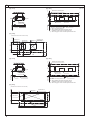
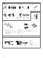
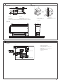
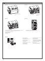
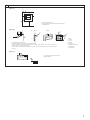
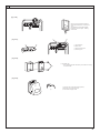
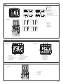
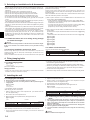
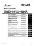
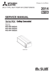
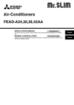
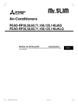
<ORIGINAL>
Air-Conditioners
PEA-RP100, 125, 140GAA
INSTALLATION MANUAL
FOR INSTALLER
For safe and correct use, please read this installation manual thoroughly before installing the air-conditioner unit.
English
3
3.2
[Fig. 3-2-2]
(Unit: mm)
Maintenance access space
75
[Fig. 3-2-1]
①
Intake air
400
25
②
③
Supply air
Ceiling
Electric box
Min.500mm
Min.500mm
Electric box
Ceiling beam
Access door 2
Drain pan
Access door 1
Access door 2
A
When connecting inlet duct.
When installing the suspension fixtures prior to
installation of the indoor unit without inlet duct.
When hanging the indoor unit directly without inlet duct.
Ceiling
①
②
③
[Fig. 3-2-3]
0 ~ 150
(Viewed from the direction of the arrow A)
Access door 1
(450 x 450)
Electric box
Supply air
Access door 2
(450 x 450)
200
585
Bottom of indoor unit
Intake air
425
0 ~ 150
400
1304
200
[Fig. 3-2-5]
75
[Fig. 3-2-4]
Maintenance access space
①
Intake air
400
25
②
③
Supply air
Electric box
Electric box
Ceiling
Access door 3
Min.300mm
Min.300mm
Ceiling beam
[Fig. 3-2-6]
50
(Viewed from the direction of the arrow B)
Supply air
Access door 3
685
Electric box
200
585
Bottom of indoor unit
Intake air
Maintenance access space
1754
400
2
1304
200
Drain pan
Access door 3
B
When
connecting
inlet
duct.
①
② When installing the suspension fixtures prior to
installation of the indoor unit without inlet duct.
③ When hanging the indoor unit directly without inlet duct.
Ceiling
4
4.1
[Fig. 4-1]
1300
235
200
Ⓐ
98
5
680
ⒶCenter of gravity
5.1
[Fig. 5-1-3]
[Fig. 5-1-2]
A
Ⓐ
10
B
*1 Ⓐ
30
A
Ⓑ
30
Ⓐ
B
[Fig. 5-1-1]
Ⓐ
Ⓑ
ⒶUnit body
ⒷLifting machine
6
ⒶBe sure to attach a U-shaped washer
(4 washers in total).
ⒶNut
ⒷWasher
6.1
[Fig. 6-1]
ⓐ
øB
øA
ⓑ
Model
PEA-RP100, 125, 140
A
ø15.88
B
ø9.52
ⓐIndoor unit
ⓑOutdoor unit
3
6
6.2
[Fig. 6-2-1]
[Fig. 6-2-2]
ⓑ
ⓐ
ⓒ
90
ⓓ
ⓑ
ⓐ
ⓕ
ⓔ
[Fig. 6-2-3]
ⓐ
ⓒ
ⓑ
ⓓ
ⓐCopper tubes
ⓑGood
ⓒNo good
ⓓTilted
ⓒSpare reamer
ⓓPipe cutter
ⓐBurr
ⓑCopper tube/pipe
ⓔUneven
ⓕBurred
[Fig. 6-2-4]
ⓐFlare nut
ⓑCopper tube
6.3
[Fig. 6-2-5]
ⓐ
ⓔ
ⓐFlaring tool
ⓑDie
ⓒCopper tube
ⓓ
ⓔ
ⓕ
ⓖ
ⓗ
ⓑ
ⓓ
ⓑ
ⓒ
[Fig. 6-3-1]
ⓑ
ⓐ
A
ⓒ
ⓒ
ⓓFlare nut
ⓔYoke
ⓘ
ⓐSmooth all around
ⓑInside is shining without
any scratches
ⓒEven length all around
ⓓToo much
ⓔTilted
ⓕScratch on
flared plane
ⓖCracked
ⓗUneven
ⓘBad examples
[Fig. 6-3-2]
Ⓗ
Ⓑ
Ⓐ
Ⓒ
Ⓙ
Ⓘ
Ⓝ
Ⓞ
Ⓓ
20
Ⓕ
20
Ⓙ
Ⓗ
Ⓞ
Ⓔ
20
20
Ⓖ
Ⓛ
Ⓚ
ⒶPipe cover (small) (accessory)
ⒷCaution:
Pull out the thermal insulation on the refrigerant piping at
the site, insert the flare nut to flare the end, and replace the
insulation in its original position.
Take care to ensure that condensation does not form on
exposed copper piping.
ⒸLiquid end of refrigerant piping
Ⓝ
ⒹGas end of refrigerant piping
ⒺSite refrigerant piping
ⒻMain body
ⒼPipe cover (large) (accessory)
ⒽThermal insulation (field supply)
ⓁEnsure that there is no gap here
ⓂPlate on main body
ⓃBand (accessory)
ⓄEnsure that there is no gap here. Place join upwards.
ⒾPull
ⒿFlare nut
ⓀReturn to original position
6.5
[Fig. 6-5]
Ⓒ
ⒶInsulator
ⒷDrain pipe R1
ⒸDrain pan
Ⓔ
Ⓕ
Ⓖ
Ⓓ
Ⓑ
4
Ⓐ
Ⓗ
Ⓘ
Ⓙ
Ⓓ 70 mm
Ⓔ 2 × Ⓕ 70 mm
Ⓕ 35 mm
ⒼDownward slope 20 mm/m or more
ⒽDrain trap
ⒾThe drain pipe should extend below this level.
ⒿOpen drain
7
7.1
[Fig. 7-1-2]
[Fig. 7-1-1]
Ⓖ
Ⓖ
Ⓓ
Ⓐ
10 mm
Ⓔ
Ⓔ
Ⓕ Ⓓ
Ⓑ
Ⓒ
Ⓐ
Ⓑ
Ⓒ
2-
12.5
20
Ⓐ Air inlet
Ⓑ Air outlet
Ⓒ Access door
Ⓓ Ceiling surface
Ⓔ Canvas duct
Ⓕ Keep duct-work length 850 or more
ⒼConnect common reference potential wire between duct-work to air conditioner
ⒶInlet duct flange
ⒸSensor protection plate
ⒺInlet duct
25~100 mm
Ⓑ Return air temperature sensor
Ⓓ Sensor fixture
[Fig. 7-1-3]
Ⓐ
34
A
B
J
E
H
I
2 × 130(=260)
25
2 × 100(=200)
K
250
Ⓒ
D
Ⓑ
G
F
C
Model
PEA-RP100, 125, 140
A
B
C
D
1102 8 × 130 (=1040) 1000 7 × 130 (=910)
8
E
330
F
105
G
45
H
31
I
35
J
22
K
95
8.1
[Fig. 8-1]
Ⓖ
Ⓕ
1
2
TB15
Indoor Power Board A
CND
L
Ⓐ
Ⓑ
Ⓒ
S1 S2
N
2
CN3C
S2 S3
1
CN22
Indoor Control Board A
S1
S1
S2
S2
S3
S3
Ⓓ
ⒶOutdoor unit power supply
ⒷEarth leakage breaker
ⒸWiring circuit breaker or isolating switch
ⒹOutdoor unit
ⒺIndoor unit/Outdoor unit connecting wire
ⒻRemote controller (option)
ⒼIndoor unit
Ⓔ
TB
S2
TB4
S1 S2
CND
Indoor Power Board B
S2 S3
CN3C
Indoor Control Board B
5
8
8.2
[Fig. 8-2-1]
[Fig. 8-2-2]
Ⓒ
Ⓐ
Ⓑ
Ⓔ
ⒶScrew holding cover (2pc)
ⒷCover
ⒸTerminal block box
ⒹKnockout hole
ⒺRemove
Ⓓ
[Fig. 8-2-3]
[Fig. 8-2-4]
1
Ⓛ
2
M1
Ⓚ
M2 S
Ⓗ
Ⓕ
Ⓙ
Ⓘ Ⓖ
ⒻUse PG bushing to keep the weight of the cable and external force from being applied to
the power supply terminal connector. Use a cable tie to secure the cable.
ⒼIndoor unit/outdoor unit connecting wire
ⒽUse ordinary bushing
ⒾRemote controller cable
Ⓙ Tensile force
[Fig. 8-2-5]
1 2
⑤
②
Ⓐ
Ⓑ
④
①
Ⓒ
⑥
③
L N
Ⓓ
⑦
6
Ⓔ
ⓀTerminal block for indoor/outdoor unit connecting wire
ⓁTerminal block for remote controller cable
ⒶIndoor terminal block
ⒷEarth wire (green/yellow)
ⒸIndoor/outdoor unit connecting wire
3-core 1.5 mm2 or more
ⒹOutdoor terminal block
ⒺPower supply cord : 2.0 mm2 or more
①Connecting cable
Cable 3-core 1.5 mm2, in conformity
with Design 245 IEC 57.
②Indoor terminal block
③Outdoor terminal block
④Always install an earth wire (1-core 1.5 mm2)
longer than other cables
⑤Remote controller cable
Wire No × size (mm2) : Cable 2C × 0.3
This wire accessory of remote controller
(wire length : 10m, non-polar. Max. 500m)
⑥Wired remote controller (option)
⑦Power supply cord
Cable 3-core 2.0 mm2 or more, in
conformity with Design 245 IEC 57.
8
8.3
[Fig. 8-3-1]
Ⓑ
30
Ⓐ
30
83.5
30
[Fig. 8-3-2]
Ⓐ
Ⓒ
Ⓕ
Ⓑ
Ⓓ
B-1.
B-2.
Ⓔ
Ⓘ
Ⓗ
ⒶRemote controller profile
ⒷRequired clearances surrounding the remote controller
ⒸInstallation pitch
120
Ⓒ
46
Ⓗ
Ⓖ
Ⓗ
Ⓘ
Ⓙ
Ⓘ
ⒸWall
ⒹConduit
ⒺLock nut
ⒶFor installation in the switch box:
ⒷFor direct installation on the wall select one of the following:
• Prepare a hole through the wall to pass the remote controller cord (in order to run the remote controller cord
from the back), then seal the hole with putty.
• Run the remote controller cord through the cut-out upper case, then seal the cut-out notch with putty similarly
as above.
ⒻBushing
ⒼSwitch box
ⒽRemote controller cord
ⒾSeal with putty
ⒿWood screw
[Fig. 8-3-3]
Ⓐ
ⒶTo the terminal block on the indoor unit
ⒷTB6 (No polarity)
AB
TB6
Ⓑ
7
8
8.4
[Fig. 8-4-1]
Ⓐ
Ⓐ
Ⓐ
OC(00)
Ⓑ
TB1
Indoor/outdoor wiring
Ⓑ
Ⓑ
Signal receiving unit wiring
ⒶOutdoor unit
ⒷRefrigerant address
ⒸIndoor unit
ⒹSignal receiving unit
TB4
IC
control board A
CN90
①
Ⓒ
Ⓓ
[Fig. 8-4-2]
Ⓐ
Ⓕ
Ⓑ
ⒶSignal receiving unit external
ⒷCenter of Switch box
ⒸSwitch box
ⒹInstallation pitch
Ⓔ6.5 mm (1/4 inch)
Ⓕ70 mm (2 - 3/4 inch)
Ⓖ83.5 ± 0.4 mm (3 - 9/32 inch)
ⒽProtrusion (pillar, etc)
Ⓔ
Ⓖ
Ⓒ
Ⓓ
Ⓗ
[Fig. 8-4-3]
Ceiling cassette type, Ceiling concealed type
Ⓐ
Indoor unit
Ⓑ
ⒶRemote controller wire
ⒷHole (drill a hole on the ceiling to pass the remote controller wire.)
ⒸSignal Receiving Unit
Ⓒ
[Fig. 8-4-4]
Ⓑ
Ⓐ
ⒶFix tightly with tape.
ⒷRemote controller wire
ⒸOrder wire
Ⓒ
[Fig. 8-4-5]
When installing directly on the wall
When using the switch box
Ⓑ
Ⓐ
Ⓒ
Wall
Ⓗ
Ⓓ
Ⓔ
Ⓖ
Ⓐ150 mm (5 - 15/16 inch)
ⒷRemote controller wire
ⒸWiring pipe
ⒹLocknut
8
Ⓘ
Ⓙ
Ⓕ
ⒺBushing
ⒻSwitch box
ⒼSeal around here with putty
ⒽSeal around here with putty
ⒾRemote controller wire
ⒿSeal around here with putty
8
8.4
[Fig. 8-4-6]
Insert the minus screwdriver toward the
arrow pointed and wrench it to remove the
cover.
A flat screwdriver whose width of blade
is between 4 and 7mm (5/32 - 9/32inch)
must be used.
[Fig. 8-4-7]
Ⓒ
Ⓐ
Ⓑ
Ⓓ
ⒶThin-wall portion
ⒷBottom case
ⒸRemote controller wire
ⒹConducting wire
[Fig. 8-4-8]
Ⓐ
ⒶScrew (M4 x 30)
* When installing the lower case directly on the wall or the ceiling,
use wood screws.
[Fig. 8-4-9]
①
①
Ⓐ
①Hang the cover to the upper hooks (2 places).
②Mount the cover to the lower case
ⒶCross-section of upper hooks
②
9
8
8.4
[Fig. 8-4-10]
JP1
JP2
JP3
JP41
JP42
CN32
SW1
CN3C
CN105
CN41
SW2
OFF
CN51
ON
CN2A
SWE
CN22
CN90
CNXB2
CN4F
CN44
CN20
CN2L
CNXA2
CNXC2
Ⓐ
<Indoor controller board>
[Fig. 8-4-11]
[Fig. 8-4-12]
IC
IC
IC
IC
IC
IC
IC
IC
Pair number: 0
Pair number: 1
Pair number: 2
Pair number: 3
Pair number: 0
Pair number: 0
Pair number: 0
Pair number: 0
CN90
CN90
Pair number: 0
CN90
Pair number: 1
Pair number: 2
CN90
CN90
CN90
Pair number: 3
Pair number: 0
[Fig. 8-4-13]
IC
IC
CN90
CN90
Pair number: 0
Pair number: 0
Pair number: 0
Pair number: 0
[Fig. 8-4-14]
Ⓐ
CHECK
ON/OFF
MODE
TEMP
FAN
AUTO STOP
VANE
AUTO START
CHECK LOUVER
TEST RUN
②,④
10
SET
h
min
RESET
CLOCK
③
CN90
CN90
8
8.5
Ⅰ Mode
[Fig. 8-5-1]
number
number
Ⅲ Refrigerant address
Ⅳ Unit number
ⒶFilter button (<Enter> button)
ⒷTEST button
ⒸSet Time button
ⒹTimer On/Off button (Set Day button)
ⒺMode selection button
ⒻSet temperature button
ⒼTimer Menu button (Monitor/Set button)
Ⅱ Setting
Ⅱ ○
Ⅲ ○
Ⅳ
○
Ⅳ
○
Ⅰ
○
TEMP.
Ⓕ
MENU
Ⓔ
BACK
Ⓖ
CHECK TEST
OPERATION
CLOCK
Ⓒ
Ⅱ
Ⅰ ○
○
Ⓐ
FILTER
DAY
MONITOR/SET
PAR-21MAA
ON/OFF
ON/OFF
Ⓑ
CLEAR
Ⅰ
○
Ⓓ
[Fig.8-5-2]
①
②
CHECK
CHECK
CHECK
ON/OFF
Ⓓ
TEMP
Ⓔ
MODE
Ⓕ
FAN
AUTO STOP
VANE
AUTO START
CHECK LOUVER
SET
④
CHECK
CHECK
Ⓐ
Ⓑ
min
RESET
③
Ⓒ
h
TEST RUN
ⒶHour button
ⒷMinute button
ⒸTEMP button
ⒹTEMP button
ⒺON/OFF button
ⒻCHECK button
CLOCK
9
9.2
Ⓕ Ⓔ
Ⓓ Ⓑ
Ⓑ
[Fig. 9-2-1]
ⒺⒹ
[Fig. 9-2-2]
Ⓒ
TEST RUN
COOL, HEAT
˚C
˚C
SIMPLE
TEMP.
MENU
BACK
MONITOR/SET
PAR-21MAA
ON/OFF
ON/OFF
FILTER
DAY
CLOCK
Ⓐ
MENU
BACK
CLEAR
PAR-21MAA
ⒽⒼ
ⒶON/OFF button
ⒷTest run display
ⒸIndoor temperature liquid line
temperature display
ⒹON/OFF lamp
ⒺPower display
SIMPLE
TEMP.
Ⓒ
CHECK TEST
OPERATION
˚C
˚C
MONITOR/SET
ON/OFF
ON/OFF
FILTER
DAY
CLOCK
CHECK TEST
OPERATION
Ⓘ Ⓜ
ⒻError code display
Test run remaining time display
ⒼSet temperature button
ⒽMode selection button
ⒾFan speed button
ⓂTEST button
ⒶCHECK button
ⒷRefrigerant address
ⒸTEMP. button
ⒹIC: Indoor unit
OC: Outdoor unit
ⒺCheck code
CLEAR
Ⓐ
9.3
TEST RUN
[Fig. 9-3]
ON/OFF
Ⓑ
Ⓐ
MODE
TEMP
FAN
AUTO STOP
VANE
AUTO START
CHECK LOUVER
TEST RUN
SET
h
Ⓒ
Ⓓ
ⒶTEST RUN button
ⒷMODE button
ⒸFAN button
ⒹVANE button
min
RESET
CLOCK
11
10
10.1
Ⓑ
[Fig. 10-1]
Ⓔ
Ⓐ
Ⓒ
Ⓓ
Ⓕ
Ⓜ
Ⓖ
Ⓛ
Ⓚ
Ⓗ
Ⓘ
Ⓙ
ⒶIndoor unit
ⒷUnion
ⒸLiquid pipe
ⒹGas pipe
ⒺStop valve
ⒻOutdoor unit
ⒼRefrigerant gas cylinder operating valve
12
ⒽRefrigerant gas cylinder for R410A with
siphon
ⒾRefrigerant (liquid)
ⒿElectronic scale for refrigerant charging
ⓀCharge hose (for R410A)
ⓁGauge manifold valve (for R410A)
ⓂService port
Contents
1.
2.
3.
4.
5.
6.
Safety precautions....................................................................................13
Selecting the installation location............................................................. 13
Selecting an installation site & Accessories............................................. 14
Fixing hanging bolts.................................................................................14
Installing the unit......................................................................................14
Refrigerant piping work............................................................................15
7. Duct work.................................................................................................16
8. Electrical work..........................................................................................17
9. Test run.....................................................................................................20
10.Maintenance.............................................................................................22
11. Specifications...........................................................................................22
Note:The phrase “Wired remote controller” in this installation manual refers only to the PAR-21MAA. If you need any information for THE PAR-31MAA, please refer to
either the installation manual or initial setting manual which are included in PAR-31MAA box.
1. Safety precautions
• Please report to or take consent by the supply authority before connection
to the system.
• Be sure to read “The following should always be observed for safety”
before installing the air conditioner.
• Be sure to observe the cautions specified here as they include important
items related to safety.
• The indications and meanings are as follows.
Warning:
Could lead to death, serious injury, etc.
Caution:
Could lead to serious injury in particular environments when operated
incorrectly.
• After reading this manual, be sure to keep it together with the instruction
manual in a handy place on the customer’s site.
Symbols put on the unit
:Indicates an action that must be avoided.
:Indicates that important instructions must be followed.
:Indicates a part which must be grounded.
:Indicates that caution should be taken with rotating parts.
:Indicates that the main switch must be turned off before servicing.
:Beware of electric shock.
:Beware of hot surface.
Warning:
Carefully read the labels affixed to the main unit.
Warning:
• Do not use refrigerant other than the type indicated in the manuals provided
with the unit and on the nameplate.
- Doing so may cause the unit or pipes to burst, or result in explosion or fire during
use, during repair, or at the time of disposal of the unit.
- It may also be in violation of applicable laws.
- MITSUBISHI ELECTRIC CORPORATION cannot be held responsible for
malfunctions or accidents resulting from the use of the wrong type of refrigerant.
• Do not install it by yourself (customer).
Incomplete installation could cause injury due to fire, electric shock,
the unit falling or leakage of water. Consult the dealer from whom you
purchased the unit or special installer.
• This appliance is not intended for use by persons (including children) with
reduced physical, sensory or mental capabilities, or lack of experience
and knowledge, unless they have been given supervision or instruction
concerning use of the appliance by a person responsible for their safety.
• This appliance is intended to be used by expert or trained users in shops,
in light industry and on farms, or for commercial use by lay persons.
• Install the unit securely in a place which can bear the weight of the unit.
When installed in an insufficient strong place, the unit could fall causing injured.
• Use the specified wires to connect the indoor and outdoor units securely
and attach the wires firmly to the terminal board connecting sections so the
stress of the wires is not applied to the sections.
Incomplete connecting and fixing could cause fire.
• Do not use intermediate connection of the power cord or the extension
cord and do not connect many devices to one AC outlet.
It could cause a fire or an electric shock due to defective contact, defective
insulation, exceeding the permissible current, etc.
• Check that the refrigerant gas does not leak after installation has completed.
• Perform the installation securely referring to the installation manual.
Incomplete installation could cause a personal injury due to fire, electric
shock, the unit falling or leakage of water.
• Perform electrical work according to the installation manual and be sure to
use an exclusive circuit.
If the capacity of the power circuit is insufficient or there is incomplete
electrical work, it could result in a fire or an electric shock.
• If the supply cord is damaged, it must be replaced by the manufacturer, its
service agent or similarly qualified persons in order to avoid a hazard.
• Attach the electrical part cover to the indoor unit and the service panel to
the outdoor unit securely.
If the electrical part cover in the indoor unit and/or the service panel in the
outdoor unit are not attached securely, it could result in a fire or an electric
shock due to dust, water, etc.
• Be sure to use the part provided or specified parts for the installation work.
The use of defective parts could cause an injury or leakage of water due to
a fire, an electric shock, the unit falling, etc.
• Ventilate the room if refrigerant leaks during operation.
If the refrigerant comes in contact with a flame, poisonous gases will be released.
• Children should be supervised to ensure that they do not play with the appliance.
• The installer and system specialist shall secure safety against leakage
according to local regulation or standards.
- Following standards may be applicable if local regulation are not available.
• Pay a special attention to the place, such as a basement, etc. where
refrigeration gas can stay, since refrigeration is heavier than the air.
Caution:
• Perform grounding.
Do not connect the ground wire to a gas pipe, water pipe arrester or
telephone ground wire. Defective grounding could cause an electric shock.
• Do not install the unit in a place where an inflammable gas leaks.
If gas leaks and accumulates in the area surrounding the unit, it could
cause an explosion.
• Install a ground leakage breaker depending on the installation place (where
it is humid).
If a ground leakage breaker is not installed, it could cause an electric shock.
• Perform the drainage/piping work securely according to the installation
manual.
If there is a defect in the drainage/piping work, water could drop from the
unit and household goods could be wet and damaged.
• Fasten a flare nut with a torque wrench as specified in this manual.
When fastened too tight, a flare nut may broken after a long period and
cause a leakage of refrigerant.
2. Selecting the installation location
2.1. Indoor unit
• Where airflow is not blocked.
• Where cool air spreads over the entire room.
• Where it is not exposed to direct sunshine.
• At a distance 1 m or more away from your TV and radio (to prevent picture from
being distorted or noise from being generated).
2.2. Outdoor unit
• Where it is not exposed to strong wind.
• Where airflow is good and dustless.
• Where it is not exposed to rain and direct sunshine.
• Where neighbours are not annoyed by operation sound or hot air.
• Where rigid wall or support is available to prevent the increase of operation
sound or vibration.
• Where there is no risk of combustible gas leakage.
• When installing the unit at a high level, be sure to fix the unit legs.
• Where it is at least 3 m away from the antenna of TV set or radio. (Otherwise,
images would be disturbed or noise would be generated.)
• In a place as far away as possible from fluorescent and incandescent lights (so
the infrared remote control can operate the air conditioner normally).
• Where the air filter can be removed and replaced easily.
• Indoor units must be installed in a ceiling with a minimum height of 2.5 meters.
Warning:
Mount the indoor unit into a ceiling strong enough to withstand the weight of
the unit.
• Install the unit horizontally.
Caution:
Avoid the following places for installation where air conditioner trouble is
liable to occur.
• Where there is too much machine oil.
• Salty environment as seaside areas.
• Hot-spring areas.
• Where sulfide gas exists.
• Other special atmospheric areas.
13
3. Selecting an installation site & Accessories
• Select a site with sturdy fixed surface sufficiently durable against the weight of unit.
• Before installing unit, the routing to carry in unit to the installation site should be
determined.
• Select a site where the unit is not affected by entering air.
• Select a site where the flow of supply and return air is not blocked.
• Select a site where refrigerant piping can easily be led to the outside.
• Select a site which allows the supply air to be distributed fully in room.
• Do not install unit at a site with oil splashing or steam in much quantity.
• Do not install unit at a site where combustible gas may generate, flow in, stagnate
or leak.
• Do not install unit at a site where equipment generating high frequency waves (a
high frequency wave welder for example) is provided.
• Do not install unit at a site where fire detector is located at the supply air side. (Fire
detector may operate erroneously due to the heated air supplied during heating
operation.)
• When special chemical product may scatter around such as site chemical plants
and hospitals, full investigation is required before installing unit. (The plastic
components may be damaged depending on the chemical product applied.)
• If the unit is run for long hours when the air above the ceiling is at high
temperature/high humidity (due point above 26 °C), due condensation may
be produced in the indoor unit. When operating the units in this condition, add
insulation material (10-20 mm) to the entire surface of the indoor unit to avoid
due condensation.
not be obstructed by beams or other objects.
[Maintenance access space]
Secure enough access space to allow for the maintenance, inspection, and
replacement of the motor, fan, drain pan, heat exchanger, and electric box in one of
the following ways.
Select an installation site for the indoor unit so that its maintenance access space
will not be obstructed by beams or other objects.
(1)When a space of 500mm or more is available below the unit between the unit
and the ceiling. [Fig. 3-2-1][Fig. 3-2-2]
• Create access door 1 and 2 (450x450 mm each) as shown in [Fig. 3-2-3].
(Access door 2 is not required if enough space is available below the unit for
a maintenance worker to work in.)
• An access hole of the same size as the access door 3 as shown in [Fig. 3-2-6]
is required to access drain pan or heat exchanger for replacement.
(Required only when the ceiling material cannot be removed.)
(2)When a space of less than 500mm is available below the unit between the unit
and the ceiling.
(At least 300 mm of space should be left below the unit as shown in [Fig. 3-2-4]
[Fig. 3-2-5].)
• Create access door 3 below the electric box and the unit as shown in [Fig. 3-2-6].
[Fig. 3-2-1] (P.2)
3.1. Install the indoor unit on a ceiling strong enough
to sustain its weight
[Fig. 3-2-2] (P.2)
Warning:
The unit must be securely installed on a structure that can sustain its weight.
If the unit is mounted on an unstable structure, it may fall down causing
injuries.
[Fig. 3-2-5] (P.2)
3.2. Securing installation and service space
[Fig. 3-2-3] (P.2)
[Fig. 3-2-4] (P.2)
[Fig. 3-2-6] (P.2)
3.3. Indoor unit accessories
The unit is provided with the following accessories:
Secure enough access space to allow for the maintenance, inspection, and
replacement of the motor, fan, drain pump, heat exchanger, and electric box in one
of the following ways.
Select an installation site for the indoor unit so that its maintenance access space will
No.
①
②
Name
Pipe cover (for refrigerant piping joint) Small diameter
Pipe cover (for refrigerant piping joint) Large diameter
Quantity
1
1
4. Fixing hanging bolts
4.1. Fixing hanging bolts
• If necessary, reinforce the hanging bolts with anti-quake supporting members as
countermeasures against earthquakes.
*Use M10 for hanging bolts and anti-quake supporting members (field supply).
[Fig. 4-1] (P.3)
ⒶCenter of gravity
(Give site of suspension strong structure.)
① Reinforcing the ceiling with additional members (edge beam, etc.) must be
required to keep the ceiling at level and to prevent the ceiling from vibrations.
Hanging structure
② Cut and remove the ceiling members.
• Ceiling: The ceiling structure varies from building to one another. For detailed
information, consult your construction company.
③ Reinforce the ceiling members, and add other members for fixing the ceiling boards.
5. Installing the unit
5.1. Hanging the unit body
2. Adjust each suspension fixture bolt.
Bring the indoor unit to an installation site as it is packed.
To hang the indoor unit, use a lifting machine to lift and pass through the
hanging bolts.
[Fig. 5-1-1] (P.3)
[Fig. 5-1-3] (P.3)
ⒶBe sure to attach a U-shaped washer (4 washers in total).
* Two installation methods are available
<When hanging the indoor unit directly>
1. Attach a washer and nut(s) to each suspension bolt. (The washers and nuts
are to be supplied locally.)
2. Fit the indoor unit to each suspension bolt.
[Fig. 5-1-2] (P.3)
ⒷWasher
(Unit: mm)
A
B
100 or more
130 or more
0 or more
30 or more
Nut (*1) is not required if distance A is 0 mm.
<When installing the suspension fixture prior to installation of the indoor unit>
1. Loosen each suspension fixture bolt slightly, and remove the fixture and
U-shaped washers.
14
When using inlet duct
When not using inlet duct
A
100 or more
25 or more
(Unit: mm)
B
130 or more
55 or more
5.2. Confirming the unit’s position and fixing hanging
bolts
3. Make sure that the unit is positioned level, then tighten each nut.
When using inlet duct
When not using inlet duct
4. Hook the indoor unit to the suspension fixtures.
5. Make sure that the unit is positioned level, then tighten each nut.
ⒶUnit body
ⒷLifting machine
ⒶNut
3. Attach a washer, nut and suspension fixture to each suspension bolt. (The
washers and nuts are to be supplied locally.)
Use the gage supplied with the panel to confirm that the unit body
and hanging bolts are positioned in place. If they are not positioned in
place, it may result in dew drops due to wind leak. Be sure to check the
positional relationship.
Install the unit horizontally, using a level. Ensure that the hanging bolt
nuts are tightened to fix the hanging bolts.
To ensure that drain is discharged, be sure to hang the unit at level using
a level.
Caution:
Be sure to install the unit body at level.
6. Refrigerant piping work
6.2.4. Flaring work
6.1. Refrigerant pipe
[Fig. 6-2-4] (P.4)
[Fig. 6-1] (P.3)
ⓐIndoor unit
ⓑOutdoor unit
Refer to the Instruction Manual that came with the outdoor unit for the restrictions on
the height difference between units and for the amount of additional refrigerant
charge.
Avoid the following places for installation where air conditioner trouble is liable to
occur.
• Where there is too much oil such as for machine or cooking.
• Salty environment as seaside areas.
• Hot-spring areas.
• Where sulfide gas exists.
• Other special atmospheric areas.
• This unit has flared connections on both indoor and outdoor sides. [Fig. 6-1]
• Insulate both refrigerant and drainage piping completely to prevent condensation.
• Refrigerant pipes of 3, 5, 7, 10 and 15 m are available as optional items.
(1)Table below shows the specifications of pipes commercially available.
Pipe
For liquid
PEARP100,
125, 140 For gas
ⓔYoke
• Carry out flaring work using flaring tool.
Pipe diameter
(mm)
9.52
15.88
Dimension
A (mm)
When the tool for R410A is used
Clutch type
0 - 0.5
0 - 0.5
+0
B ‑0.4 (mm)
13.2
19.7
Firmly hold copper tube in a die in the dimension shown in the table at above.
6.2.5. Check
[Fig. 6-2-5] (P.4)
Piping preparation
Model
ⓐFlaring tool
ⓑDie
ⓒCopper tube
ⓓFlare nut
Outside diameter
mm
inch
Min wall
thickness
Insulation
thickness
9.52
3/8
0.8 mm
8 mm
15.88
5/8
1.0 mm
8 mm
Insulation
material
Heat resisting
foam plastic
0.045 specific
gravity
(2)Ensure that the 2 refrigerant pipes are well insulated to prevent condensation.
(3)Refrigerant pipe bending radius must be 10 cm or more.
Caution:
Using careful insulation of specified thickness. Excessive thickness prevents
storage behind the indoor unit and smaller thickness causes dew drippage.
6.2. Flaring work
• Main cause of gas leakage is defect in flaring work.
Carry out correct flaring work in the following procedure.
6.2.1. Pipe cutting
[Fig. 6-2-1] (P.4)
ⓐCopper tubes
ⓑGood
ⓒNo good
ⓓTilted
ⓔUneven
ⓕBurred
• Using a pipe cutter cut the copper tube correctly.
6.2.2. Burrs removal
[Fig. 6-2-2] (P.4)
ⓐBurr
ⓑCopper tube/pipe
ⓒSpare reamer
ⓓPipe cutter
• Completely remove all burrs from the cut cross section of pipe/tube.
• Put the end of the copper tube/pipe to downward direction as you remove burrs
in order to avoid burrs drop in the tubing.
6.2.3. Putting nut on
[Fig. 6-2-3] (P.4)
ⓐFlare nut
ⓑCopper tube
• Remove flare nuts attached to indoor and outdoor unit, then put them on pipe/
tube having completed burr removal.
(not possible to put them on after flaring work)
ⓐSmooth all around
ⓑInside is shining without any scratches
ⓒEven length all around
ⓓToo much
ⓕScratch on flared plane
ⓖCracked
ⓗUneven
ⓘBad examples
ⓔTilted
• Compare the flared work with a figure in right side hand.
• If flare is noted to be defective, cut off the flared section and do flaring work again.
6.3. Pipe connection
[Fig. 6-3-1] (P.4)
• Apply a thin coat of refrigeration oil on the seat surface of pipe.
• For connection first align the center, then tighten the first 3 to 4 turns of flare nut.
• Use tightening torque table below as a guideline for indoor unit side union joint
section, and tighten using two wrenches. Excessive tightening damages the flare
section.
Copper pipe O.D.
(mm)
ø9.52
ø15.88
Flare nut O.D.
(mm)
22
29
Tightening torque
(N·m)
34 - 42
68 - 82
Warning:
Be careful of flying flare nut! (Internally pressurized)
Remove the flare nut as follows:
1. Loosen the nut until you hear a hissing noise.
2. Do not remove the nut until the gas has been completely released (i.e.,
hissing noise stops).
3. Check that the gas has been completely released, and then remove the nut.
Outdoor unit connection
Connect pipes to stop valve pipe joint of the outdoor unit in the same manner
applied for indoor unit.
• For tightening use a torque wrench or spanner, and use the same tightening
torque applied for indoor unit.
Refrigerant pipe insulation
• After connecting refrigerant piping, insulate the joints (flared joints) with thermal
insulation tubing.
[Fig. 6-3-2] (P.4)
ⒶPipe cover (small) (accessory)
ⒷCaution:
Pull out the thermal insulation on the refrigerant piping at the site, insert the flare nut to
flare the end, and replace the insulation in its original position.
Take care to ensure that condensation does not form on exposed copper piping.
ⒸLiquid end of refrigerant piping Ⓓ Gas end of refrigerant piping
ⒺSite refrigerant piping
Ⓕ Main body
ⒼPipe cover (large) (accessory)
Ⓗ Thermal insulation (field supply)
ⒾPull
Ⓙ Flare nut
ⓀReturn to original position
Ⓛ Ensure that there is no gap here
ⓂPlate on main body
Ⓝ Band (accessory)
ⓄEnsure that there is no gap here. Place join upwards.
15
6. Refrigerant piping work
1.Remove and discard the rubber bung which is inserted in the end of the unit piping.
2.Flare the end of the site refrigerant piping.
3.Pull out the thermal insulation on the site refrigerant piping and replace the
insulation in its original position.
Cautions On Refrigerant Piping
Be sure to use non-oxidative brazing for brazing to ensure that no foreign
matter or moisture enter into the pipe.
Be sure to apply refrigerating machine oil over the flare connection
seating surface and tighten the connection using a double spanner.
Provide a metal brace to support the refrigerant pipe so that no load is
imparted to the indoor unit end pipe. This metal brace should be provided
50 cm away from the indoor unit’s flare connection.
6.4. Purging procedures leak test
PURGING PROCEDURES
Connect the refrigerant pipes (both the liquid and gas pipes) between the indoor
and the outdoor units.
Remove the service port cap of the stop valve on the side of the outdoor unit gas pipe.
(The stop valve will not work in its initial state fresh out of the factory (totally
closed with cap on).)
-0.101MPa Compound pressure
Stop valve (-760 mmHg) gauge (for R410A)
Pressure gauge
(for R410A)
*Close
Stop valve
*Open
Hexagonal wrench
*4 to 5 turns
Gauge manifold
valve (for R410A)
Handle High
Handle
Low
Charge hose
Stop
(for R410A)
valve
Vacuum
(or the vacuum
Service port
pump
pump with the
Window
function to
Adapter for
prevent the back
Charge hose preventing
flow)
(for R410A)
the back flow
Remove the gage manifold valve quickly from the service port of the stop valve.
After refrigerant pipes are connected and evacuated, fully open all stop valves on
gas and liquid pipe sides.
Operating without fully opening lowers the performance and causes trouble.
Pipe length :
7 m maximum
No gas charge is needed.
Pipe length exceeding 7 m
Charge the prescribed
amount of gas.
Connect the gage manifold valve and the vacuum pump to the service port of the
stop valve on the gas pipe side of the outdoor unit.
Run the vacuum pump. (Vacuumize for more than 15 minutes.)
Tighten the cap to the service port to obtain the initial status.
Retighten the cap
Check the vacuum with the gage manifold valve, then close the gage manifold
valve, and stop the vacuum pump.
Leave it as is for one or two minutes. Make sure the pointer of the gage manifold
valve remains in the same position. Confirm that the pressure gage show -0.101MPa
(-760 mmHg).
Leak test
6.5. Drain piping work
[Fig. 6-5] (P.4)
ⒶInsulator
ⒷDrain pipe R1
ⒸDrain pan
Ⓓ 70 mm
Ⓕ 35 mm
Ⓔ 2 × Ⓕ 70 mm
ⒼDownward slope 20 mm/m or more
ⒽDrain trap
ⒾThe drain pipe should extend below this level.
ⒿOpen drain
7. Duct work
• In connecting duct, insert canvas duct between unit and duct.
• Use incombustible material for duct parts.
• Provide full insulation to inlet duct flange, outlet duct flange and outlet duct to
prevent condensation.
• Be sure to apply the air filter near the air inlet grille.
• Before connecting an inlet duct, install the air filter in the inlet grille.
[Fig. 7-1-1] (P.5)
ⒶAir inlet
ⒷAir outlet
ⒸAccess door
ⒹCeiling surface
ⒺCanvas duct
ⒻKeep duct-work length 850 or more
ⒼConnect common reference potential wire between duct-work to air conditioner
•
•
•
•
Caution:
Inlet duct of 850 mm or more should be construted.
To connect the air conditioner main body and the duct for potential
equalization.
To reduce the risk of injury from metal sheet edges, wear protective gloves.
Install sufficient thermal insulation to prevent condensation forming on
outlet duct flanges and outlet ducts.
To avoid electrical noise interference, do not run transmission lines at
the bottom of the unit.
• Return air temperature sensor when an inlet duct is installed.
A return air temperature sensor is installed on the inlet duct flange. Before
connecting an inlet duct, this sensor must be removed and installed in the
specified position.
16
[Fig. 7-1-2] (P.5)
ⒶInlet duct flange
ⒸSensor protection plate
ⒺInlet duct
ⒷReturn air temperature sensor
ⒹSensor fixture
① Pull out the sensor, and remove the sensor fixture and protection plate. (The
protection plate must be discarded.)
② Connect the inlet duct.
③ Drill a sensor hole (ø12.5 dia.) on the side on the duct.
④ Assemble the sensor and fixture.
• When pulling out the sensor, do not pull it by the lead wire. Doing so may result
in wire breakage.
• Before connecting the inlet duct, make sure that the sensor, its fixture and
protection plate are removed.
• The sensor removed in step ① must be re-installed in the position specified
in the drawing. Installation of the sensor in an incorrect position may result in
malfunction.
Mount holes for outlet duct flange and inlet duct.
[Fig. 7-1-3] (P.5)
ⒶInlet duct flange
ⒷOutlet duct flange
ⒸTop of the unit
8. Electrical work
8.1. Power supply
8.1.1. Indoor unit power supplied from outdoor unit
[Fig. 8-1] (P.5)
ⒶOutdoor unit power supply
ⒷEarth leakage breaker
ⒸWiring circuit breaker or isolating switch
ⒹOutdoor unit
ⒺIndoor unit/outdoor unit connecting cords
ⒻRemote controller (option)
ⒼIndoor unit
[Fig. 8-2-5] (P.6)
ⒶIndoor terminal block
ⒷEarth wire (green/yellow)
ⒸIndoor/outdoor unit connecting wire 3-core 1.5 mm2 or more
Circuit
rating
Wiring Wire No.
× size (mm2)
Field electrical wiring
Indoor unit model
PEA
Indoor unit power supply (Heater)
–
Indoor unit power supply (Heater) earth
–
3 × 1.5 (polar)
Indoor unit-Outdoor unit
1 × Min. 1.5
Indoor unit-Outdoor unit earth
2 × 0.3 (Non-polar)
Remote controller-Indoor unit *1
Indoor unit (Heater) L-N *2
–
Indoor unit-Outdoor unit S1-S2 *2
230 V AC
Indoor unit-Outdoor unit S2-S3
*2
24 V DC
Remote controller-Indoor unit *2
14 V DC
*1.The 10 m wire is attached in the remote controller accessory. Max. 500 m
*2.The figures are NOT always against the ground.
S3 terminal has 24 V DC against S2 terminal. However between S3 and S1, these terminals
are not electrically insulataed by the transformer or other device.
Notes: 1. Wiring size must comply with the applicable local and national
code.
2. Power supply cords and indoor unit/outdoor unit connecting
cords shall not be lighter than polychloroprene sheathed flexible
cord. (Design 245 IEC57)
3. Install an earth longer than other cables.
• PEA-RP∙GAA has two power boards and two control boards respectively.
(AB in Fig. 8-1)
Check the wiring details on the plate affixed to the unit and be sure not to wire
incorrectly.
• PEA-RP∙GAA has two control boards. Therefore, “No.1” unit or “No.2” unit is
displayed on the remote controller when an initial setup is performed or an error
occurs.
Control Board A is not always No.1 unit and Control Board B is not always No.2
unit. Check the both control boards in case of a malfunction of the fan motor or
the sensor.
• Connect the connectors of external input/output devices to the circuit board to
which the remote controller is connected.
8.2. Indoor wire connection
Please identify the model name of the operation manual attached on the terminal
block box with that shown on the rating name plate.
1. Remove the screw (2pcs) holding the cover to dismount the cover.
[Fig. 8-2-1] (P.6)
ⒶScrew holding cover (2pcs)
Ⓑ Cover
2. Open knockout holes
(Recommend to use a screwdriver or the like for this work.)
[Fig. 8-2-2] (P.6)
ⒸTerminal block box
ⒺRemove
• Use the specified indoor/outdoor unit connecting wire to connect the
indoor and outdoor units and fix the wire to the terminal block securely so
that no stress is applied to the connecting section of the terminal block. Incomplete connection or fixing of the wire could result in a fire.
• Do not pinch the cables or wires when attaching the terminal block box
cover. Doing so may cause a risk of disconnection.
• When accommodating the terminal block box, make sure that the connectors
on the box side are not removed. If removed, it cannot operate normally.
Ⓓ Knockout hole
3. Fix indoor unit/outdoor unit connecting wire to terminal block box by using buffer
bushing for tensile force. (PG connection or the like.) Connect remote controller
cable to terminal block through the knockout hole of terminal block box using
ordinary bushing.
[Fig. 8-2-3] (P.6)
ⒻUse PG bushing to keep the weight of the cable and external force from being applied to
the power supply terminal connector. Use a cable tie to secure the cable.
ⒼIndoor unit/outdoor unit connecting wire Ⓗ Use ordinary bushing
Ⓙ Tensile force
Ⓘ Remote controller cable
[Fig. 8-2-4] (P.6)
ⓀTerminal block for indoor/outdoor unit connecting wire
ⓁTerminal block for remote controller cable
4. After wiring is complete, make sure again that there is no slack on the
connections, and attach the cover onto the terminal block box in the reverse
order of removal.
Warning:
• Attach the electrical part cover securely. If it is attached incorrectly, it could
result in a fire, electric shock due to dust, water, etc.
ⒹOutdoor terminal block
ⒺPower supply cord : 2.0 mm2 or more
①Connecting cable
Cable 3-core 1.5 mm2, in conformity with Design 245 IEC 57.
②Indoor terminal block
③Outdoor terminal block
④Always install an earth wire (1-core 1.5 mm2) longer than other cables
⑤Remote controller cable
Wire No × size (mm2) : Cable 2C × 0.3
This wire accessory of remote controller
(wire length : 10 m, non-polar. Max. 500 m)
⑥Wired remote controller (option)
⑦Power supply cord
  Cable 3-core 2.0 mm2 or more, in conformity with Design 245 IEC 57.
• Perform wiring as shown in [Fig. 8-2-5] (P.6). (Procure the cable locally.)
Make sure to use cables of the correct polarity only.
• Connect the terminal blocks as shown in [Fig. 8-2-5] (P.6).
Caution:
• Use care not to make mis-wiring.
• Firmly tighten the terminal screws to prevent them from loosening.
• After tightening, pull the wires lightly to confirm that they do not move.
8.3. Remote controller (wired remote controller (option))
8.3.1. For wired remote controller
1) Installing procedures
(1)Select an installing position for the remote controller.
The temperature sensors are located on both remote controller and indoor unit.
Procure the following parts locally:
Two piece switch box
Thin copper conduit tube
Lock nuts and bushings
[Fig. 8-3-1] (P.7)
ⒶRemote controller profile
ⒷRequired clearances surrounding the remote controller
ⒸInstallation pitch
(2)Seal the service entrance for the remote controller cord with putty to prevent
possible invasion of dew drops, water, cockroaches or worms.
[Fig. 8-3-2] (P.7)
ⒶFor installation in the switch box:
ⒷFor direct installation on the wall select one of the following:
• Prepare a hole through the wall to pass the remote controller cord (in order to run the
remote controller cord from the back), then seal the hole with putty.
• Run the remote controller cord through the cut-out upper case, then seal the cut-out notch
with putty similarly as above.
ⒸWall
ⒼSwitch box
ⒹConduit
ⒽRemote controller cord
ⒺLock nut
ⒾSeal with putty
ⒻBushing
ⒿWood screw
B-1. To lead the remote controller cord from the back of the controller:
B-2. To run the remote controller cord through the upper portion:
(3)For direct installation on the wall
2) Connecting procedures
① Connect the remote controller cord to the terminal block.
[Fig. 8-3-3] (P.7)
ⒶTo the terminal block on the indoor unit
ⒷTB6 (No polarity)
② Set the dip switch No.1 shown below when using two remote controller’s for the
same group.
3) Function selection of remote controller
If two remote controllers are connected, set one to “Main” and the other to “Sub”.
For setting procedures, refer to “Function selection of remote controller” in the
operation manual for the indoor unit.
17
8. Electrical work
8.4. Remote controller (wireless remote controller
(option))
8.4.1. For wireless remote controller (option)
(3)Seal the Signal Receiving Unit cord lead-in hole with putty in order to prevent
the possible entry of dew, water droplets, cockroaches, other insects, etc.
[Fig. 8-4-5] (P.8)
Ⓐ150 mm (5 - 15/16 inch)
ⒷRemote controller wire
ⒸWiring pipe
ⒹLocknut
1) Installation area
• Area in which the remote controller is not exposed to direct sunshine.
• Area in which there is no near by heating source.
• Area in which the remote controller is not exposed to cold (or hot) winds.
• Area in which the remote controller can be operated easily.
• Area in which the remote controller is beyond the reach of children.
* The signal can travel up to approximately 7 meters (in a streight line) within 45 degrees to
both right and left of the center line of the receiver.
* Connect the infrared remote controller signal receiver sensor to the circuit board on the A-side.
8.4.2. Signal Receiving Unit
1) Sample system connection
[Fig. 8-4-1] (P.8)
Only the wiring from the signal receiving unit and between the remote controllers is
shown in [Fig. 8-4-1]. The wiring differs depending on the unit to be connected or
the system to be used.
For details on restrictions, refer to the installation manual or the service handbook
that came with the unit.
1. Connecting to Mr. SLIM air conditioner
(1)Standard 1:1
① Connecting the signal receiving unit
Connect the signal receiving unit to the CN90 (Connect to the wireless
remote controller board) on the indoor unit using the supplied remote
controller wire. Connect the signal receiving units to all the indoor units.
2) How To Install
[Fig. 8-4-2] (P.8) to [Fig. 8-4-9] (P.9)
1. Common items for “Installation on the ceiling” and “Installation on the
switch box or on the wall”
[Fig. 8-4-2] (P.8)
ⒶSignal receiving unit external
ⒷCenter of Switch box
ⒸSwitch box
ⒹInstallation pitch
Ⓔ6.5 mm (1/4 inch)
Ⓕ70 mm (2 - 3/4 inch)
Ⓖ83.5 ± 0.4 mm (3 - 9/32 inch)
ⒽProtrusion (pillar, etc)
[Fig. 8-4-3] (P.8)
ⒶRemote controller wire
ⒷHole (drill a hole on the ceiling to pass the remote controller wire.)
ⒸSignal Receiving Unit
(1)Select the installation site.
The following must be observed.
① Connect the signal receiving unit to the indoor unit with the supplied remote
controller wire. Note that the length of the remote controller wire is 5 m (16
ft). Install the remote controller within the reach of the remote controller wire.
② When installing on either the switch box or the wall, allow space around the
Signal Receiving Unit as shown in the figure in [Fig. 8-4-2].
③ When installing the Signal Receiving Unit to the switch box, the Signal
Receiving Unit slipped downward for 6.5 mm (1/4 inch) as right illustrated.
④ Parts which must be supplied on site.
Switch box for one unit
Thin-copper wiring pipe
Lock nut and bushing
⑤ The thickness of the ceiling to which the remote controller is installed must
be between 9 mm (3/8 inch) and 25 mm (1 inch).
⑥ Install the unit on the ceiling or on the wall where the signal can be received
from the wireless remote controller.
The area where the signal from the wireless remote controller can be
received is 45 ° and 7 m (22 ft) away from the front of the signal receiving
unit.
⑦ Install the signal receiving unit to the position depending on the indoor unit
model.
⑧ Connect the remote controller wire securely to the order wire. To pass the
remote controller wire through the conduit.
[Fig. 8-4-4] (P.8)
ⒶFix tightly with tape.
ⒷRemote controller wire
ⒸOrder wire
Note:
• The point where the remote controller wire is connected differs depending
on the indoor unit model.
Take into account that the remote controller wire cannot be extended
when selecting the installation site.
• lf the Signal Receiving Unit is installed near a fluorescent lamp specially
inverter type, signal interception may occur.
Be careful for installing the Signal Receiving Unit or replacing the lamp.
(2)Use the remote controller wire to connect it to the connector (CN90) on
the controller circuit board on the indoor unit.
18
ⒺBushing
ⒻSwitch box
ⒼSeal around here with putty
• When installing on the switch box, seal the connections between the switch
box and wiring pipe with putty.
[Fig. 8-4-5] (P.8)
ⒽSeal around here with putty
ⒾRemote controller wire
ⒿSeal around here with putty
• When opening a hole using a drill for Signal Receiving Unit wire (or taking the
wire out of the back of the Signal Receiving Unit), seal that hole with putty.
• When routing the wire via the portion cut off from the upper case, equally
seal that portion with putty.
(4)Install the remote control wire to the terminal block. [Fig. 8-4-6] (P.9)
(5)Installing hole when the Signal Receiving Unit is installed on the wall direct.
[Fig. 8-4-7] (P.9)
• Cut the thin-wall portion inside the bottom case (oblique section) by a knife or a
nipper.
• Take out the connected remote controller wire to the terminal block through
this space.
(6)Install the lower case on the switch box or directly on the wall. [Fig. 8-4-8] (P.9)
Mounting the cover [Fig. 8-4-9] (P.9)
Caution:
• Insert the cover securely until the clicking sound is made. If not doing so,
the cover may fall.
8.4.3. Setting
1) Setting the pair number switch
[Fig. 8-4-10] (P.10)
1. Setting method
Assign the same pair number to the wireless remote controller as that of the
indoor unit. If not doing so, the remote controller cannot be operated. Refer to
the installation manual that came with the wireless remote controller for how to
set pair numbers of wireless remote controllers.
Position of daisy wire on the controller circuit board on the indoor unit.
Controller circuit board on the indoor unit (reference) [Fig. 8-4-10] (P.10)
Ⓐ CN90: Connector for remote controller wire connection
For pair number settings, the following 4 patters (A-D) are available.
Pair number
setting pattern
Pair number on
Indoor controller circuit board side Point
remote controller side
where the daisy wire is disconnected
A
B
C
D
0
1
2
3~9
Not disconnected
J41 disconnected
J42 disconnected
J41 and J42 disconnected
2. Setting example
(1)To use the units in the same room
[Fig. 8-4-11] (P.10)
① Separate setting
Assign a different pair number to each indoor unit to operate each indoor
unit by its own wireless remote controller.
[Fig. 8-4-12] (P.10)
② Single setting
Assign the same pair number to all the indoor units to operate all the indoor
units by a single wireless remote controller.
[Fig. 8-4-13] (P.10)
(2)To use the units in different rooms
Assign the same pair number to the wireless remote controller as that of the
indoor unit. (Leave the setting as it is at purchase.)
2) Setting the Model No.
[Fig. 8-4-14] (P.10)
① Insert batteries.
② Press the SET button with something sharp at the end.
MODEL SELECT blinke and Model No. lighted.
button to set the Model No.
③ Press the temp
④ Press the SET button with something sharp at the end.
MODEL SELECT and Model No. are lighted for three seconds, then turned off.
Indoor Unit Model
Ⓐ Model No.
PEA
251
8. Electrical work
8.5. Function settings (Function selection via the
remote controller)
8.5.1 Function setting on the unit (Selecting the unit functions)
1) For wired remote controller [Fig. 8-5-1] (P.11)
1. Changing the external static pressure setting.
• Be sure to change the external static pressure setting depending on the duct and
the grill used.
① Go to the function setting mode.
Switch OFF the remote controller.
Press the Ⓐ and Ⓑ buttons simultaneously and hold them for at least 2
seconds. FUNCTION will start to flash.
② Use the Ⓒ button to set the refrigerant address ( Ⅲ ) to 00.
③Press Ⓓ and [--] will start to flash in the unit number ( Ⅳ ) display.
④ Use the Ⓒ button to set the unit number ( Ⅳ ) to AL.
⑤Press the Ⓔ MODE button to designate the refrigerant address/unit number.
[--] will flash in the mode number (Ⅰ) display momentarily.
⑥ Press the Ⓕ buttons to set the mode number (Ⅰ) to 08.
⑦ Press the Ⓖ button and the current set setting number ( Ⅱ ) will flash.
Use the Ⓕ button to switch the setting number in response to the external static
pressure to be used.
External static
pressure
50 Pa (before shipment)
100 Pa
150 Pa
Setting no. of mode
no. 08
1
2
3
Setting no. of mode
no. 10
1
1
1
⑧ Press the MODE button Ⓔ and mode and the setting number (Ⅰ) and ( Ⅱ ) will
change to being on constantly and the contents of the setting can be confirmed.
⑨ Press the FILTER Ⓐ and TEST RUN Ⓑ buttons simultaneously for at least two
seconds. The function selection screen will disappear momentarily and the air
conditioner OFF display will appear.
⑩To set the static pressure at 100, 150Pa, repeat steps ③ to ⑨. (Set the mode
number to 10 for step ⑥.)
2. Other functions
① Select unit number 00 for the settings. (Settings for all indoor units)
Refer to Function table 1.
② Select unit number AL for the settings.
Refer to Function table 2.
2) For wireless remote controller [Fig. 8-5-2] (P.11)
1. Changing the external static pressure setting.
• Be sure to change the external static pressure setting depending on the duct and
the grill used.
① Go to the function select mode
Press the CHECK button Ⓕ twice continuously.
(Start this operation from the status of remote controller display turned off.)
CHECK is lighted and “00” blinks.
Press the TEMP button Ⓒ once to set “50”. Direct the wireless remote controller
toward the receiver of the indoor unit and press the Hour button Ⓐ.
② Setting the unit number
Press the TEMP button Ⓒ and Ⓓ to set the unit number to 07. Direct the
wireless remote controller toward the receiver of the indoor unit and press the
Minute button Ⓑ.
③ Selecting a mode
Enter 08 to change the external static pressure setting using the Ⓒ and Ⓓ
buttons.
Direct the wireless remote controller toward the receiver of the indoor unit and
press the Hour button Ⓐ.
Current setting number:
1 = 1 beep (one second)
2 = 2 beeps (one second each)
3 = 3 beeps (one second each)
④ Selecting the setting number
Use the Ⓒ and Ⓓ buttons to change the external static pressure setting to be
used.
Direct the wireless remote controller toward the sensor of the indoor unit and press the Hour button Ⓐ.
⑤ To set the external static pressure
Repeat steps ③ and ④ to set the mode number to 10.
⑥ Complete function selection
Direct the wireless remote controller toward the sensor of the indoor unit and
press the ON/OFF button Ⓔ.
Note:
• Whenever changes are made to the function settings after installation or
maintenance, be sure to record the changes with a mark in the “Setting”
column of the Function table.
3) Changing the power voltage setting (Function table 1)
• Be sure to change the power voltage setting depending on the voltage used.
Function table 1
Select unit number 00
Mode
Power failure automatic recovery*1
(AUTO RESTART FUNCTION)
Indoor temperature detecting
LOSSNAY connectivity
Power voltage
Auto mode
Settings
Not available
Available
Indoor unit operating average
Set by indoor unit’s remote controller
Remote controller’s internal sensor
Not Supported
Supported (indoor unit is not equipped with outdoor-air intake)
Supported (indoor unit is equipped with outdoor-air intake)
240V
220V, 230V
Energy saving cycle automatically enabled
Energy saving cycle automatically disabled
Mode no.
01
02
03
04
05
Setting no. Initial setting
(*1)
1
2
1
2
3
1
2
3
1
2
1
2
Check
Setting no. Initial setting
1
2
3
1
2
3
1
2
3
Check
Function table 2
Select unit number AL [wired remote controller]/07 [wireless remote controller]
Mode
Filter sign
External static pressure
Settings
100 Hr
2500 Hr
No filter sign indicator
External static
pressure
50 Pa
100 Pa
150 Pa
Mode no.
07
Setting no. of
mode no. 08
1
2
3
Setting no. of
mode no. 10
1
1
1
08
10
*1 When the power supply returns, the air conditioner will start 3 minutes later.
Note:When the function of an indoor unit were changed by function selection after the end of installation, always indicate the contents by entering a
appropriate check filed of the tables.
or other mark in the
19
9. Test run
9.1. Before test run
After completing installation and the wiring and piping of the indoor and
outdoor units, check for refrigerant leakage, looseness in the power supply or
control wiring, wrong polarity, and no disconnection of one phase in the supply.
Use a 500-volt megohmmeter to check that the resistance between the
power supply terminals and ground is at least 1.0 MΩ.
Do not carry out this test on the control wiring (low voltage circuit)
terminals.
Warning:
Do not use the air conditioner if the insulation resistance is less than 1.0 MΩ.
Insulation resistance
After installation or after the power source to the unit has been cut for an
extended period, the insulation resistance will drop below 1 MΩ due to refrigerant
accumulating in the compressor. This is not a malfunction. Perform the following
procedures.
1. Remove the wires from the compressor and measure the insulation resistance
of the compressor.
2. If the insulation resistance is below 1 MΩ, the compressor is faulty or the
resistance dropped due the accumulation of refrigerant in the compressor.
3. After connecting the wires to the compressor, the compressor will start to warm
up after power is supplied. After supplying power for the times indicated below,
measure the insulation resistance again.
• The insulation resistance drops due to accumulation of refrigerant in the
compressor. The resistance will rise above 1 MΩ after the compressor is
warmed up for two to three hours.
(The time necessary to warm up the compressor varies according to
atmospheric conditions and refrigerant accumulation.)
• To operate the compressor with refrigerant accumulated in the compressor,
the compressor must be warmed up at least 12 hours to prevent breakdown.
4. If the insulation resistance rises above 1 MΩ, the compressor is not faulty.
Caution:
• The compressor will not operate unless the power supply phase connection
is correct.
• Turn on the power at least 12 hours before starting operation.
- Starting operation immediately after turning on the main power switch can result
in severe damage to internal parts. Keep the power switch turned on during the
operational season.
9.2. Test run
9.2.1. Using wired remote controller (option)
① Turn on the power at least 12 hours before the test run.
② Press the [TEST] button twice. ➡ “TEST RUN” liquid crystal display
③ Press the [Mode selection] button. ➡ Make sure that wind is blown out.
④ Press the [Mode selection] button and switch to the cooling (or heating) mode.
➡ Make sure that cold (or warm) wind is blown out.
⑤ Press the [Fan speed] button. ➡ Make sure that the wind speed is switched.
⑥ Check operation of the outdoor unit fan.
⑦ Release test run by pressing the [ON/OFF] button. ➡ Stop
⑧ Register a telephone number.
The telephone number of the repair shop, sales office, etc., to contact if an
error occurs can be registered in the remote controller. The telephone number
will be displayed when an error occurs. For registration procedures, refer to the
operation manual for the indoor unit.
[Fig. 9-2-1] (P.11)
ⒶON/OFF button
ⒷTest run display
ⒸIndoor temperature liquid line temperature display
ⒹON/OFF lamp
ⒺPower display
ⒻError code display
Test run remaining time display
ⒼSet temperature button
ⒽMode selection button
ⒾFan speed button
ⓂTEST button
9.2.2. Wired remote controller
① Turn on the power.
② Press the [CHECK] button twice.
③ Set refrigerant address with [TEMP] button if system control is used.
④ Press the [ON/OFF] button to stop the self-check.
[Fig. 9-2-2] (P.11)
ⒶCHECK button
ⒷRefrigerant address
ⒸTEMP. button
ⒹIC: Indoor unit
OC: Outdoor unit
ⒺCheck code
• For description of each check code, refer to the following table.
① Check code
P1
P2, P9
E6, E7
P4
P5
PA
PB
P6
EE
P8
E4
Fb
E0, E3
E1, E2
E9
UP
U3, U4
UF
U2
U1, Ud
U5
U8
U6
U7
U9, UH
Others
Symptom
Intake sensor error
Pipe (Liquid or 2-phase pipe) sensor error
Indoor/outdoor unit communication error
Drain sensor error
Drain pump error
Forced compressor error
Fan motor error
Freezing/Overheating safeguard operation
Communication error between indoor and outdoor units
Pipe temperature error
Remote controller signal receiving error
Indoor unit control system error (memory error, etc.)
Remote controller transmission error
Remote controller control board error
Indoor/outdoor unit communication error (Transmitting error) (Outdoor unit)
Compressor overcurrent interruption
Open/short of outdoor unit thermistors
Compressor overcurrent interruption (When compressor locked)
Abnormal high discharging temperature/49C worked/insufficient refrigerant
Abnormal high pressure (63H worked)/Overheating safeguard operation
Abnormal temperature of heat sink
Outdoor unit fan safeguard stop
Compressor overcurrent interruption/Abnormal of power module
Abnormality of super heat due to low discharge temperature
Abnormality such as overvoltage or voltage shortage and abnormal synchronous signal to main circuit/
Current sensor error
Other errors (Refer to the technical manual for the outdoor unit.)
• On wired remote controller
① Check code displayed in the LCD.
20
Remark
Each unit has two each of the
following: intake sensors, liquid
pipe sensors, 2-phase pipe
sensors, and fan motors. When
a problem occurs with one of
any of the items above, an error
code (P1, P2, P8, P9, or PB)
will appear. When an error code
appears, check both of the items.
For details, check the LED display
of the outdoor controller board.
9. Test run
9.3. Test run
9.3.1. Using wireless remote controller (option)
[Fig. 9-3] (P.11)
① Turn on the power to the unit at least 12 hours before the test run.
② Press the TEST RUN button Ⓐ twice continuously.
(Start this operation from the status of remote controller display turned off.)
TEST RUN and current operation mode are displayed.
③ Press the MODE button Ⓑ to activate COOL mode, then check whether cool
air is blown out from the unit.
④ Press the MODE button Ⓑ to activate HEAT mode, then check whether warm
air is blown out from the unit.
⑤ Press the FAN button Ⓒ and check whether fan speed changes.
⑥ Press the VANE button Ⓓ and check whether the auto vane operates properly.
⑦ Press the ON/OFF button to stop the test run.
Note:
• Point the remote controller towards the indoor unit receiver while
following steps ② to ⑦.
• It is not possible to run the in FAN, DRY or AUTO mode.
[Output pattern A] Errors detected by indoor unit
Wireless remote controller
Wired remote
controller
Beeper sounds/OPERATION
INDICATOR lamp flashes
(Number of times)
Check code
1
2
3
4
5
6
7
8
9
10
11
12
No sound
P1
P2, P9
E6, E7
P4
P5
P6
EE
P8
E4
–
PB
Fb
––
Symptom
Remark
Intake sensor error
Pipe (Liquid or 2-phase pipe) sensor error
Indoor/outdoor unit communication error
Drain sensor error
Drain pump error
Freezing/Overheating safeguard operation
Communication error between indoor and outdoor units
Pipe temperature error
Remote controller signal receiving error
–
Fan motor error
Indoor unit control system error (memory error, etc.)
No corresponding
[Output pattern B] Errors detected by unit other than indoor unit (outdoor unit, etc.)
Wireless remote controller
Beeper sounds/OPERATION INDICATOR
lamp flashes (Number of times)
1
2
3
4
5
6
7
8
9
10
11
12
13
14
Symptom
Indoor/outdoor unit communication error (Transmitting error) (Outdoor unit)
Compressor overcurrent interruption
Open/short of outdoor unit thermistors
Compressor overcurrent interruption (When compressor locked)
Abnormal high discharging temperature/49C worked/ insufficient refrigerant
Abnormal high pressure (63H worked)/ Overheating safeguard operation
Abnormal temperature of heat sink
Outdoor unit fan protection stop
Compressor overcurrent interruption/Abnormal of power module
Abnormality of super heat due to low discharge temperature
Abnormality such as overvoltage or voltage shortage and abnormal
synchronous signal to main circuit/Current sensor error
–
–
Other errors (Refer to the technical manual for the outdoor unit.)
Remark
For details, check the LED
display of the outdoor controller
board.
*1 If the beeper does not sound again after the initial two beeps to confirm the self-check start signal was received and the OPERATION INDICATOR lamp does
not come on, there are no error records.
*2 If the beeper sounds three times continuously “beep, beep, beep (0.4 + 0.4 + 0.4 sec.)” after the initial two beeps to confirm the self-check start signal was
received, the specified refrigerant address is incorrect.
• On wireless remote controller
The continuous buzzer sounds from receiving section of indoor unit.
Blink of operation lamp
• On wired remote controller
Check code displayed on the LCD.
• Check that all LEDs on the two control boards on the indoor unit are lit or blinking (3 each, 6 total).
• If the unit cannot be operated properly after the above test run has been performed, refer to the following table to remove the cause.
Symptom
Cause
Wired remote controller
LED 1, 2 (PCB in outdoor unit)
•For about 2 minutes after power-on, operation of the
After LED 1, 2 are lighted, LED 2 is turned
For about 2 minutes
PLEASE WAIT
remote controller is not possible due to system start-up.
off, then only LED 1 is lighted. (Correct
following power-on
(Correct operation)
operation)
•Connector for the outdoor unit’s protection device is not
connected.
Only LED 1 is lighted. → LED 1, 2 blink.
PLEASE WAIT → Error code
•Reverse or open phase wiring for the outdoor unit’s power
After about 2
terminal block (L1, L2, L3)
minutes has expired
Display messages do not appear
•Incorrect
wiring between indoor and outdoor units (incorrect
following power-on
even when operation switch is
Only LED 1 is lighted. → LED 1, 2 blinks
polarity of S1, S2, S3)
turned ON (operation lamp does
twice, LED 2 blinks once.
•Remote controller wire short
not light up).
21
9. Test run
On the wireless remote controller with conditions above, following phenomena takes place.
• No signals from the remote controller are accepted.
• OPE lamp is blinking.
• The buzzer makes a short ping sound.
Note:
Operation is not possible for about 30 seconds after cancellation of function selection. (Correct operation)
For description of each LED (LED1, 2, 3) provided on the indoor controller, refer to the following table.
LED 1 (power for microcomputer)
Indicates whether control power is supplied. Make sure that this LED is always lit.
LED 2 (power for remote controller)
Indicates whether power is supplied to the remote controller. This LED lights only in the case of
LED 3 (communication between indoor and outdoor units)
the indoor unit which is connected to the outdoor unit refrigerant address “0”.
Indicates state of communication between the indoor and outdoor units. Make sure that this LED is
always blinking.
9.4. AUTO RESTART FUNCTION
Indoor controller board
This model is equipped with the AUTO RESTART FUNCTION.
When the indoor unit is controlled with the remote controller, the operation mode, set temperature, and the fan speed are memorized by the indoor controller board.
The auto restart function sets to work the moment the power has restored after power failure, then, the unit will restart automatically.
Set the AUTO RESTART FUNCTION using the remote controller. (Mode no.01)
10.Maintenance
10.1. Gas charge
Note:
In case of adding refrigerant, comply with the quantity specified for the refrigerating
cycle.
[Fig. 10-1] (P.12)
Ⓐ Indoor unit
Ⓑ Union
Ⓒ Liquid pipe
Ⓓ Gas pipe
Ⓔ Stop valve
Ⓕ Outdoor unit
Ⓖ Refrigerant gas cylinder operating valve
Ⓗ Refrigerant gas cylinder for R410A with siphon
Ⓘ Refrigerant (liquid)
Ⓙ Electronic scale for refrigerant charging
Ⓚ Charge hose (for R410A)
Ⓛ Gauge manifold valve (for R410A)
Ⓜ Service port
Caution:
• Do not discharge the refrigerant into the atmosphere.
Take care not to discharge refrigerant into the atmosphere during
installation, reinstallation, or repairs to the refrigerant circuit.
• For additional charging, charge the refrigerant from liquid phase of the gas
cylinder.
If the refrigerant is charged from the gas phase, composition change may
occur in the refrigerant inside the cylinder and the outdoor unit. In this
case, ability of the refrigerating cycle decreases or normal operation can be
impossible. However, charging the liquid refrigerant all at once may cause
the compressor to be locked. Thus, charge the refrigerant slowly.
1. Connect gas cylinder to the service port of stop valve (3-way).
2. Execute air purge of the pipe (or hose) coming from refrigerant gas
cylinder.
3. Replenish specified amount of refrigerant, while running the air
conditioner for cooling.
11.Specifications
Model
Power input
Current
PEA-RP100GAA
PEA-RP125, 140GAA
kW
0.21
0.49
A
1.83
3.84
42-34
60-48
54-43
52-41
42-39
45-42
63
63
50Pa
Air flow rate
100Pa m3/min
(Hi-Lo)
150Pa
Sound level at 50Pa
dB(A)
(Hi-Lo)
Weight
22
kg
To maintain the high pressure of the gas cylinder, warm the gas cylinder with warm
water (under 40°C) during cold season. But never use naked fire or steam.
Please be sure to put the contact address/telephone number on
this manual before handing it to the customer.
HEAD OFFICE: TOKYO BLDG., 2-7-3, MARUNOUCHI, CHIYODA-KU, TOKYO 100-8310, JAPAN
KD79M111H02