1
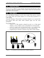
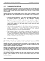
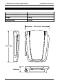
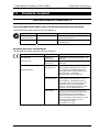
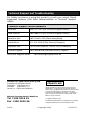
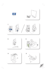
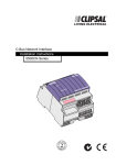
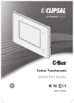
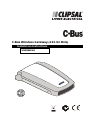
C-Bus Wireless Gateway (433.92 MHz)
Installation Instructions
5800WCGA
© Copyright Clipsal Integrated Systems Pty Ltd 2004–2008. All rights reserved.
This material is copyright under Australian and international laws. Except as
permitted under the relevant law, no part of this work may be reproduced by any
process without prior written permission of and acknowledgement to Clipsal
Australia Pty Ltd.
Clipsal and C-Bus are registered trademarks of Clipsal Australia Pty Ltd.
Schedule Plus and HomeGate are trademarks of Clipsal Australia Pty Ltd.
Encryption by QUALCOMM
The information in this manual is provided in good faith. Whilst Clipsal Australia Pty
Ltd, CAPL) has endeavoured to ensure the relevance and accuracy of the
information, it assumes no responsibility for any loss incurred as a result of its use.
CAPL does not warrant that the information is fit for any particular purpose, nor
does it endorse its use in applications that are critical to the health or life of any
human being. CAPL reserves the right to update the information at any time
without notice.
V2.0 Dec 2005 / Aug 2008.
C-Bus Wireless Gateway (433.92 MHz)
Installation Instructions
Contents
1.0
2.0
3.0
4.0
5.0
6.0
7.0
8.0
Important Note
Description
Installation Procedure
3.1
Mounting Instructions
3.2
Wiring Instructions
Configuration and Programming
4.1
Connecting to a Wireless Network
4.2
Connecting to a Wired Network
4.3
Gateway Identification
4.4
Communication Options
4.5
Status Reporting
Electrical Specifications
Mechanical Specifications
Standards Complied
Warranty
5
5
6
6
6
7
7
8
9
10
10
11
12
13
14
3
C-Bus Wireless Gateway (433.92 MHz)
4
Installation Instructions
C-Bus Wireless Gateway (433.92 MHz)
1.0
Installation Instructions
Important Note
The use of any software not provided by Clipsal Integrated Systems (CIS) in
conjunction with the installation of this product may void any warranties
applicable to the hardware.
2.0
Description
The C-Bus Wireless Gateway is used to link a single C-Bus wireless network
to a single C-Bus Cat-5 wired network. It is functionally equivalent to a
C-Bus bridge.
Using the Gateway, C-Bus wireless and wired networks can communicate
and interact with each other. Both network types use the same
commands.
The Gateway allows:
• control of a C-Bus wireless network by units on a C-Bus wired
network, or from software such as Schedule Plus and HomeGate
• control of output units and electrical loads in one network type,
from input units (such as switches) in the other network type
• programming of a wireless network using C-Bus Toolkit software.
N
A/L
CLIPSAL
1 2 3
2
4 5
6 7 8 A/L N
N1
C-Bus
UNIT
N2
C-Bus
Dimmer
C-Bus CONNECTIONS
Gateway
Figure 1 — A Gateway links wired and wireless networks together
5
C-Bus Wireless Gateway (433.92 MHz)
3.0
Installation Instructions
Installation Procedure
It is important to select the right location to install a C-Bus Wireless
Gateway. Some considerations are listed below:
• There is a LEARN button on the base of the Gateway. This needs
to be accessible during setup, so that the unit can be connected to
the wireless network.
• The unit should be located centrally to other C-Bus Wireless units
so that all units are within range of each other.
• Choose a location free of water, humidity, direct sunlight and
heavy dust.
• Allow adequate ventilation.
• Do not cover the unit.
• The C-Bus Wireless Gateway is designed for indoor use only.
no wet
hands
3.1
no cleaner
spray
no
coverage
no direct
sunshine
no
dust
Mounting Instructions
The C-Bus Wireless Gateway can be placed horizontally on a convenient
surface. Adhesive feet are provided for attachment to the base of the unit.
Alternatively, the Gateway can be mounted on a wall using the keyhole
cut-outs located on the base of the unit. These have 40 mm fixing centres.
If wall mounting, ensure the unit can be removed easily, to allow access to
the LEARN button on its base.
3.2
Wiring Instructions
Plug a C-Bus Cat-5 cable connected to the wired C-Bus network into either
of the RJ45 sockets at the rear/top of the Gateway. The RJ45 sockets are
connected in parallel. Power is provided to the unit by the wired C-Bus
network.
6
C-Bus Wireless Gateway (433.92 MHz)
4.0
Installation Instructions
Configuration and Programming
Before the Gateway can be used, it needs to be connected to a wireless
and wired C-Bus network. The connection to a wireless network is
accomplished by a learn operation. The connection to a wired network
requires the use of the C-Bus Toolkit software.
4.1
Connecting to a Wireless Network
These steps are illustrated in Figure 2. To link the Gateway to a C-Bus
Wireless network:
1) Select a C-Bus Wireless wall switch or plug adapter on the network
you want to link to.
2) Press and hold the top two buttons for 10 seconds (until the unit’s
indicator lights start flashing alternately). This activates learn
mode on the wireless network.
3) Press the LEARN button on the base of the Gateway (shown in
Figure 3). An indicator light at the front of the Gateway starts
flashing slowly. You must complete step 4 within 3 minutes of
pressing the LEARN button.
4) Go back to the unit to be linked to. Hold down the left topmost
button and, while continuing to hold, quickly double-press the
right topmost button.
5) The slow flashing indicator light on the Gateway will flash quickly
for about one second, and then turn off. This confirms that the
Gateway has been linked to the C-Bus Wireless network. Press and
hold the top two buttons on the wall switch or plug adapter for
1 second, to exit learn mode.
Unit on network
to be linked to
10 second press
Quick press
Hold left button
Double-press right
LEARN
Step 1
Step 2
Step 3
Step 4
Figure 2 — Connecting the Gateway to a wireless network
7
C-Bus Wireless Gateway (433.92 MHz)
Installation Instructions
5800WCGA
C-Bus Wireless Gateway
C-Bus Supply: 15-36Vdc, 32mA
RF Frequency: 433.92MHz
Patent Pending
WARNING: This unit must be
used with CLIPSAL C-Bus system
only.
C-Bus
Network
Address
C-Bus
Network
Address
LEARN
button
LEARN
Made in Australia
Figure 3 — The LEARN button is on the base of the Gateway
4.2
Connecting to a Wired Network
To connect the Gateway to a C-Bus wired Cat-5 network:
1) Plug the Gateway into the wired C-Bus network as described in
section 3.2.
2) Use the C-Bus Toolkit software to configure the wired side of the
Gateway. Note the following points,
• The Unit Address of the wired near side of the Gateway
(GATEWLSN) must match the Network Address of the C-Bus
Wireless network being linked to.
• The Unit Address of the wireless far side of the Gateway
(WGATE5F) must match the Network Address of the C-Bus
wired network being linked to.
• After using the “Scan Network” function in the Project Manager
“Units” view, the Gateway appears as a unit on the wired C-Bus
network. You can select the Gateway in this view and use the
“Make Network” function, to create and open the connected
C-Bus Wireless network.
8
C-Bus Wireless Gateway (433.92 MHz)
Installation Instructions
A current version of C-Bus Toolkit software may be downloaded from
www.clipsal.com (the Clipsal Integrated Systems web site). It is
recommended that programming by software be performed by trained
C-Bus installers.
4.3
Gateway Identification
A Gateway is a form of C-Bus bridge which links wired and wireless C-Bus
networks. Bridges and Gateways consist of two separate internal subunits, one for each network connection. Several Gateways may be used
within a C-Bus installation. When scanning an installation, Gateways
identify themselves with different names, depending on their connection
type, and their position in the network.
Figure 4 shows a diagram of an installation with multiple networks. The
installation includes two wired networks linked through a wireless
network. Two Gateways are used. When scanning the networks using
C-Bus Toolkit software connected via the PC Interface (PCI), four Gateway
sub-units can be seen.
Wireless network
GATEWLSN
WGATE5N
PCI
Gateway
N
Gateway
A/L
N
WGATE5F
Cat-5 wired network
A/L
GATEWLSF
Cat-5 wired network
Figure 4 — Identification of Gateways when scanning from a PCI
9
C-Bus Wireless Gateway (433.92 MHz)
4.4
Installation Instructions
Communication Options
The Gateway supports explicit routing of messages into and through both
wired and wireless networks. Such messages are used by control software
such as C-Bus Toolkit and control devices such as the C-Touch Colour
Touch Screen.
Several options are available when using C-Bus Toolkit software to edit
the Gateway unit. The following options are included on the “Connection”
tab:
•
•
•
4.5
Send to adjacent network — this causes standard messages (such
as button presses) on either of the specified “Connect
Applications” to be sent to the adjacent wired or wireless network.
When this option is enabled, a unit with a specific Group Address
on one side of the Gateway will be associated with units with the
same Group Address on the other side (if units have the same
Application Address).
Send to other remote network — this allows standard messages on
either of the specified “Connect Applications” to be sent from the
wireless network to a remote (non-adjacent) C-Bus network
(possibly through one or more network bridges).
Synchronise to wired — this option is present on the wireless far
side of the Gateway, and applies when the Gateway is powered up.
It causes the Gateway to retrieve the levels of groups in the wired
C-Bus network, and set the levels of corresponding groups in the
wireless network to the same values.
Status Reporting
Wired C-Bus networks use a status reporting system (known as an MMI).
This provides automatic detection and correction of discrepancies
between the states of grouped inputs and outputs. It also allows the C-Bus
Toolkit software, and special C-Bus control units, to take a snapshot of the
states of units or groups in the network.
Wireless C-Bus networks use a different method of status reporting, which
is slower but better suited to a radio transmission/reception environment.
The Wireless C-Bus status reporting system serves the same purpose as
the wired C-Bus MMI.
The Gateway translates between the two status reporting types, allowing
wireless C-Bus networks to be scanned and browsed using the C-Bus
Toolkit software.
10
C-Bus Wireless Gateway (433.92 MHz)
Installation Instructions
After powering up, the Gateway may take up to 1 minute to obtain a
complete view of the wireless network. Under some circumstances, the
Gateway can take 30 to 60 seconds to recognise that a unit has been
added to or removed from a wireless network.
When using C-Bus Toolkit software to view units on a wireless network, an
‘Update’ button is provided to cause the Gateway to rediscover all wireless
units.
5.0
Electrical Specifications
Parameter
Description
C-Bus supply voltage
15 to 36 V DC, 32 mA
RF frequency
433.92 MHz
Transmitting power
1 mW
Typical range
(Range depends on building
construction and the proximity
to dense or metallic objects)
15 to 20 m (in buildings with timber
frame/brick veneer construction)
10 to 15 m (in buildings with brick,
stone or steel frame construction)
5 to 10 m (in buildings with steel
reinforced concrete construction)
Maximum range
50 m (open air)
Operating temperature range
0 to 40 °C
Operating humidity range
10 to 95% RH
11
C-Bus Wireless Gateway (433.92 MHz)
6.0
Installation Instructions
Mechanical Specifications
Parameter
Description
Dimensions (W×H×D)
105 × 149 × 26 mm
Weight
105 g
Fixing centres
40 mm
105.0 mm
149.0 mm
26.0 mm
12
C-Bus Wireless Gateway (433.92 MHz)
7.0
Installation Instructions
Standards Complied
DECLARATIONS OF CONFORMITY
Australian/New Zealand EMC & Electrical Safety Frameworks and Standards
The 5800WCGA model complies with the following:
Regulation
Standard
Title
Radio
Communications
AS/NZS 4268
Radio Equipment and Systems
– Short Range Devices
EMC
AS/NZS CISPR22
Information Technology Equipment
– RF Emissions
European Directives and Standards
The 5800WCGA model complies with the following:
European Council Directive
Standard
Title
89/336/EEC
CISPR 22,
EN 50022
Information Technology Equipment - RF
emissions
EMC Directive
CISPR 24,
EN 55024
Information Technology Equipment Immunity
1999/5/EC
ETSI
EN 300 220-1
EMC and ERM; Short Range Devices
(SRD); Radio equipment to be used in
the 25 MHz to 1000 MHz frequency
range with power levels ranging up to
500 mW; Part 1: Technical
characteristics and test methods
ETSI
EN 300 220-3
EMC and ERM; Short Range Devices
(SRD); Radio equipment to be used in
the 25 MHz to 1000 MHz frequency
range with power levels ranging up to
500 mW; Part 3: Harmonized EN
covering essential requirements under
article 3.2 of the R&TTE Directive
EN 50385
Product standard to demonstrate the
compliances of radio base stations and
fixed terminal stations for wireless
telecommunication systems with the
basic restrictions or the reference levels
related to human exposure to RF
electromagnetic fields
(110 MHz to 40 GHz)
R&TTE Directive
13
C-Bus Wireless Gateway (433.92 MHz)
8.0
Installation Instructions
Warranty
The C-Bus Wireless Gateway product carries a two-year warranty against
manufacturing.
Warranty Statement
1) The benefits conferred herein are in addition to, and in no way shall be
deemed to derogate; either expressly or by implication, any or all
other rights and remedies in respect to Clipsal Australia Pty Ltd
product, which the consumer has under the Commonwealth Trade
Practices Act or any other similar State or Territory Laws.
2) The warrantor is Clipsal Australia Pty Ltd with registered offices in all
Australian States.
3) This Clipsal product is guaranteed against faulty workmanship and
materials for a period of two (2) years from the date of installation.
4) Clipsal Australia Pty Ltd reserves the right, at its discretion, to either
repair free of parts and labour charges, replace or offer refund in
respect to any article found to be faulty due to materials, parts or
workmanship.
5) This warranty is expressly subject to the Clipsal product being
installed, wired, tested, operated and used in accordance with the
manufacturer's instructions.
6) All costs of a claim shall be met by Clipsal Australia Pty Ltd, however
should the product that is the subject of the claim be found to be in
good working order, all such costs shall be met by the claimant.
7) When making a claim, the consumer shall forward the Clipsal
Integrated Systems Product to the nearest office of Clipsal Australia
Pty Ltd with adequate particulars of the defect within 28 days of the
fault occurring. The product should be returned securely packed,
complete with details of the date and place of purchase, description of
load, and circumstances of malfunction.
For all warranty enquiries, contact your local Clipsal sales representative.
The address and contact number of your nearest Clipsal Australia office
can be found at http://www.clipsal.com or by telephoning Technical
Support (refer to the back page).
14
C-Bus Wireless Gateway (433.92 MHz)
Installation Instructions
This page is intentionally left blank.
15
Technical Support and Troubleshooting
For further assistance in using this product, consult your nearest Clipsal
Integrated Systems (CIS) Sales Representative or Technical Support
Officer.
Technical Support Contact Numbers
Australia
1300 722 247 (CIS Technical Support Hotline)
New Zealand
0800 888 219 (CIS Technical Support Hotline)
Northern Asia
+852 2484 4157 (Clipsal Hong Kong)
South Africa
011 314 5200 (C-Bus Technical Support)
Southern Asia
+603 7665 3555 Ext. 236 or 242 (CIS Malaysia)
United Kingdom
0870 608 8 608 (Schneider Electric Support)
Technical Support email:
[email protected]
Product of Clipsal Australia Pty Ltd
A member of Schneider Electric
Telephone (08) 8269 0511
Facsimile
(08) 8340 1724
Contact us: clipsal.com/feedback
National Customer Service Enquiries
Tel 1300 2025 25
Fax 1300 2025 56
F1903
clipsal.com
Clipsal Australia Pty Ltd reserves the right to change
specifications, modify designs and discontinue items
without incurring obligation and whilst every effort is made
to ensure that descriptions, specifications and other
information in this catalogue are correct, no warranty is
given in respect thereof and the company shall not be
liable for any error therein.
© Clipsal Australia Pty Ltd.
The identified trademarks and copyrights are the property
of Clipsal Australia Pty Ltd unless otherwise noted.
© Copyright 2008
10312671