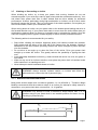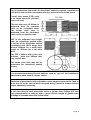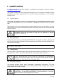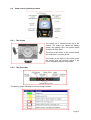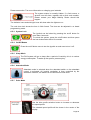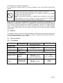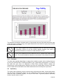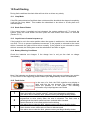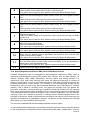
1
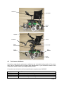
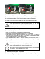
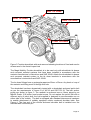
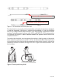
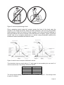
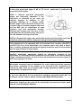
Owners Manual – V6 all models
Page 1
1 Power Wheelchair Owner’s Manual
Thank you for choosing a Magic Mobility Product. We are proud of the quality construction of
every chair we build. This owner’s manual explains the operation of your new chair. Please
read it carefully as it contains important safety, care and maintenance information.
Magic Mobility’s Power Wheelchair series may be custom made to measure and may vary in
detail from chair to chair however they should all comply to the enclosed basic specifications.
As a manufacturer of wheelchairs, Magic Mobility endeavours to supply a wide variety of
features and options to meet the needs of the user. However, final selection and
specifications of the type of wheelchair to be used by any individual rests solely with the user
and his/her healthcare professional capable of making such a selection.
All of the information and specifications in this document are current at the time of printing.
However due to our policy of continual product improvements we reserve the right to make
changes at any time without notice. This may lead to slight variations between the
illustrations and explanations in this manual and the model you have purchased.
1.1
Intended Use
The intended use of Magic Mobility Power Wheelchair’s is to provide mobility to persons with
a maximum weight of 401 lbs. limited to a sitting position, that have the capability of
operating a powered wheelchair.
If you experience any problems with your power chair that you are unable to solve, or if you
do not feel capable of safely following any of the instructions and/or recommendations as
contained in this manual, please contact your Magic Mobility dealer. You will find the model
designation and serial number of the wheelchair on the base of the frame.
Magic Mobility is not liable for damage to property or personal injury arising out of unsafe use
of a power chair. Magic Mobility is also not liable for any property damage or personal injury
arising out of the failure of any person and/or user to following the instructions and
recommendations set forth in this manual.
SEATING ARRANGEMENT
MAXIMUM USER WEIGHT
No seat elevator fitted
401 lbs
Seat elevator fitted
341 lbs
2 Safety and Damage Warnings
Throughout this manual, you will find the following safety and damage warnings.
WARNING! This is a warning which, if ignored, may cause injury to yourself
and other people
STOP! This is an instruction that, if not followed, may result in damage to
your Power chair. It means ‘do not do this’ or ‘do not let this happen’.
Page 2
Contents
1
2
3
4
5
6
7
Power Wheelchair Owner’s Manual ................................................................................ 2
1.1 Intended Use ............................................................................................................ 2
Safety and Damage Warnings ........................................................................................ 2
Safety ............................................................................................................................. 5
3.1 Transfers .................................................................................................................. 5
3.2 Motor Vehicle Transport ........................................................................................... 5
3.3 Weight Limitations .................................................................................................... 6
3.4 Stairs and Escalators................................................................................................ 6
3.5 Transportation Products .............................................................................................
3.6 Public Streets and Roadways ................................................................................... 6
3.7 Stationary Obstacles: (Steps, Curbs, Etc.)................................................................ 6
3.8 Climbing or Descending an Incline ........................................................................... 7
3.8.1 Maximum Recommended Incline ....................................................................... 7
3.9 Removable Parts ...................................................................................................... 8
3.10
Cornering Information............................................................................................ 8
3.11
Electromagnetic Fields (for more information see section 10) ............................... 8
3.12
Positioning Belts.................................................................................................... 8
3.13
Weather Precautions............................................................................................. 9
3.14
Reaching and Bending .......................................................................................... 9
3.15
Prescription Drugs/Physical Limitations................................................................. 9
3.16
Alcohol .................................................................................................................. 9
Specifications.................................................................................................................. 9
4.1 The Frontier.............................................................................................................. 9
4.2 Features and Options ............................................................................................... 9
4.3 Performance Attributes............................................................................................10
Operating Instructions....................................................................................................11
5.1 Performance adjustments........................................................................................11
5.2 Comfort adjustments ...............................................................................................11
5.3 Freewheel Mode – pushing the power chair ............................................................11
5.4 Tilt in space seat option – if applicable ....................................................................12
5.5 Power elevating seat option – if applicable ..............................................................12
Joystick controls.............................................................................................................20
6.1 Joystick power .........................................................................................................20
6.2 Rain and Water .......................................................................................................20
6.3 Joystick lead............................................................................................................20
6.4 Controller program...................................................................................................20
6.5 Hand control joystick operation................................................................................21
6.5.1 The Screen .......................................................................................................21
6.5.2 The Status Bar ..................................................................................................21
6.5.3 System Lock .....................................................................................................22
6.5.4 On/Off Button ....................................................................................................22
6.5.5 Sleep Mode.......................................................................................................22
6.5.6 Attendant Mode.................................................................................................22
6.5.7 Drive Mode........................................................................................................22
6.5.8 Accessory Mode ...............................................................................................23
6.5.9 On Board Programming ....................................................................................23
6.5.10
Lighting Mode (if applicable) ..........................................................................25
6.5.11
Charging ........................................................................................................25
Batteries & Charging......................................................................................................26
7.1 Batteries ..................................................................................................................26
7.2 Battery Charging......................................................................................................26
7.3 Charging Procedure ................................................................................................26
To get the maximum range from your batteries: ................................................................27
7.4 Public Transportation...............................................................................................27
Page 3
7.5 Battery Disposal and Recycling ...............................................................................27
Care & Maintenance ......................................................................................................27
8.1 General Guidelines..................................................................................................27
8.2 Batteries ..................................................................................................................28
8.3 Tires and Castors ....................................................................................................28
8.3.1 Tire Inflation ......................................................................................................28
8.3.2 Tire Wear ..........................................................................................................29
8.4 Upholstery ...............................................................................................................29
8.5 Cleaning ..................................................................................................................30
8.6 Storage....................................................................................................................30
8.7 Transportation .........................................................................................................30
8.8 Daily Checks ...........................................................................................................30
8.9 Weekly Checks........................................................................................................30
8.10
Annual Checks .....................................................................................................31
9 Servicing ........................................................................................................................31
10
Fault finding ................................................................................................................32
10.1
Limp Mode ...........................................................................................................32
10.2
Stuck Power Button..............................................................................................32
10.3
Joystick out of neutral at power up .......................................................................32
10.4
Battery Warning Conditions..................................................................................32
10.5
Fault Codes..........................................................................................................32
10.6
Electromagnetic Interference (EMI) From Radio Wave Sources...........................33
10.7
Powered Wheelchair Electromagnetic Interference (EMI).....................................34
11
Warranty.....................................................................................................................35
12
Head Office and Operations .......................................................................................35
8
Page 4
3 Safety
Please read and follow all instructions in this owner’s manual before attempting to operate
your power chair for the first time. If there is anything in this manual you do not understand,
or if you require additional assistance for setup, contact your Magic Mobility Dealer before
operating the wheelchair.
There are certain situations, including some medical conditions, where the power chair user
will need to practice operating the power chair in the presence of a trained attendant. A
trained attendant can be defined as a family member or care professional specially trained in
assisting a power chair user in various daily living activities.
The contents of this manual are based on the expectation that a qualified healthcare
professional has properly fitted the power chair to the user and the prescribing healthcare
professional has trained the user in the operation of the wheelchair, the dangers that can be
encountered and assured themselves that the user is capable of this.
Using your Magic Mobility product safely also depends upon your own good judgement
and/or common sense, as well as that of your provider, caregiver, and/or health professional.
Magic Mobility is not responsible for injuries and/or damage resulting from any person’s
failure to follow the warnings, cautions and instructions in this owner’s manual.
WARNING! If you are going to be stationary in your power chair for an
extended period of time, turn off the power. This will conserve battery power
and remove the chance of unexpected chair movement through inadvertent
joystick contact or from electromagnetic sources
3.1
Transfers
It is recommended that you have a trained attendant present while you learn to transfer
yourself. To reduce the chance of injury, we recommend:
•
•
•
•
Be sure the power is turned off (See section 6.5.4)
Be sure the Power chair is not in freewheel mode (See section 5.3)
Ensure armrests and footrests are swung away or removed
Position yourself as far back as possible in the power chair seat to prevent the power
chair from tipping forward.
WARNING! Avoid putting all your weight on either armrests or footrests. This
may cause the power chair to tip and cause injury
STOP! Avoid putting all your weight on either armrests or footrests. This may
damage their supports.
3.2
Motor Vehicle Transport
Wheelchair positioning belts are not designed with the intent of providing proper restraint
during motor vehicle transportation. A WC19 and ISO7176-19 compliant system is available
from Magic Mobility. More information is contained in section 5.6.
Page 5
If it is necessary to use a transportation product such as a hoist or lift, Magic Mobility
recommends that the manufacturer’s instructions and specifications are closely reviewed
before using that product
3.3
Weight Limitations
Your power chair is rated for a maximum weight capacity of 401 lbs. Do not carry passengers
or heavy weights on any part of the wheelchair.
SEATING ARRANGEMENT
MAXIMUM USER WEIGHT
No seat elevator fitted
401 lbs.
Seat elevator fitted
341 lbs.
WARNING! Exceeding the weight capacity voids your warranty and may
result in personal injury.
STOP! Exceeding the weight capacity voids your warranty and may result in
damage to your power chair.
3.4
Stairs and Escalators
WARNING! Never use your power chair to negotiate stairs or escalators.
Always use an elevator or lift. You may cause injury to yourself and to others.
STOP! Trying to negotiate stairs or escalators may result in damage to your
power chair.
3.5
Public Streets and Roadways
WARNING! You should not operate your power chair on public streets and
roadways. Be aware that it may be difficult for traffic to see you when you are
seated on your power chair. Obey all local pedestrian traffic rules. Wait until
your path is clear of traffic, and then proceed with extreme caution
3.6
Stationary Obstacles: (Steps, Curbs, Etc.)
Proceed with extreme caution when driving near raised surfaces, unprotected ledges, and/or
drop-offs (curbs, porches, stairs, escalators, elevators, etc). Always approach an obstacle so
both front wheels touch that obstacle together. Never attempt to climb a curb or obstacle at
an angle.
WARNING! Do not attempt to have your power chair climb or descend an
obstacle that is higher than 2 in. unless you have the assistance of an
attendant. Never try to travel backwards down any step, curb, or other
obstacle. This may cause the power chair to tip and cause personal injury.
Page 6
3.7
Climbing or Descending an Incline
When climbing an incline, try to keep your power chair moving; however do not use
excessive speed. If you must stop, start up again slowly and then accelerate cautiously. Your
mid wheel drive power chair has 4 castor wheels and two drive wheels for enhanced
performance. At times, particularly during high acceleration on inclines, not all of the 4 castor
wheels will contact the ground. This is a normal part of the chairs operation; if at anytime you
feel uncomfortable, reduce your acceleration rate.
When driving down an incline, set your power chair to the slowest speed setting and drive in
the forward direction only. If your power chair starts to move down the incline faster than you
anticipated or desired, allow it to come to a complete stop by releasing the joystick. Once the
chair has stopped push the joystick forward slightly to ensure a safely controlled descent.
The following advice is recommended for your safety:
•
•
•
•
•
Stop before climbing an obstacle. Approach slowly until castors contact the obstacle.
Apply power and the action of the chair will lift the castors over the obstacle. Weight is
transferred to the drive wheels providing traction and motor strength to power the chair
over the obstacle.
Do not drive at an angle up or down the face of the incline. Drive your power chair
straight up or down the incline. This greatly reduces the possibility of tipping the chair
over
Avoid potentially hazardous inclines e.g. areas covered with snow, ice, mud, cut grass, or
wet leaves.
When on any sort of an incline or decline, never place the power chair in freewheel mode
while seated on it or standing next to it.
Never attempt to travel backwards down an incline.
WARNING! Always exercise extreme caution on inclines and follow the
advice above to reduce the risk of personal injury
3.7.1
Maximum Recommended Incline
Most public access ramps have a maximum gradient 1 in 14 (AS1428.1). Therefore, Magic
Mobility recommends that the maximum slope of an incline you attempt to safely ascend or
descend on your power chair does not exceed a 1 in 14 gradient.
4.1°
1
WARNING! Any attempt to climb or descend a slope steeper than 1 in 14
gradient may put your power chair in an unstable position and cause it to tip,
resulting in personal injury.
14
Page 7
3.8
Removable Parts
WARNING! Do not attempt to lift or move a power chair by any of its
removable parts. This may result in personal injury.
STOP! Do not attempt to lift or move a power chair by any of its removable
parts. This may cause damage to the chair.
3.9
Cornering Information
Despite front and rear castor wheels, excessively high cornering speeds can still create the
possibility of tipping. If you feel that you may tip over in a corner, immediately reduce your
speed and steering angle (i.e. lessen the sharpness of the turn)
The following advice is recommended for your safety:
•
•
•
•
•
•
Reduce cornering speed
Reduce steering angle
Beware of uneven, rough and slippery terrain
Avoid turning on inclined surfaces
Be aware of changing surfaces - such as passing from a paved area to a gravel area at
high speed while turning
Avoid abrupt directional changes.
WARNING! When cornering, lower your speed and follow the advice above to
reduce the risk of personal injury
3.10 Electromagnetic Fields (for more information see section 10)
Your power chair’s performance may be influenced by electromagnetic fields caused by
mobile telephones or other radiating devices, such as hand-held radios, radio and television
stations, wireless computer links, microwave sources, and pagers.
Your power chair may also be a source of electromagnetic and radio frequency interference.
Be aware that your power chair may affect the performance of alarm systems and other
radiating devices.
WARNING! Turn off your power chair when using products, which emit
electromagnetic fields. This will eliminate the possibility of unintended
movement caused by electromagnetic sources. Failure to take this precaution
may result in personal injury
3.11 Positioning Belts
Do not use the positioning belt on your power chair as a restraint for transportation in a motor
vehicle.
Page 8
It is the obligation of the purchasers, therapists and other healthcare professionals to
determine if a positioning belt is required to ensure the safe operation of this equipment by
the user.
WARNING! Ensure your positioning belt is fastened securely. Serious
personal injury may result if you fall from the power chair.
3.12 Weather Precautions
WARNING! Do not operate your power chair in icy or slippery conditions or
on salted surfaces (i.e.; footpaths and roads). Such use may adversely affect
the performance and safety of your power chair, resulting in an accident and
personal injury.
3.13 Reaching and Bending
WARNING! Do not bend, lean, or reach for objects, if you have to pick them
up from the floor we suggest you use a specially designed “Pick Up Stick”.
Movements such as these may cause your power chair to tip, possibly
resulting in personal injury.
3.14 Prescription Drugs/Physical Limitations
Consult your physician if you are taking prescribed or over-the-counter medication or if you
have certain physical limitations.
WARNING! Some medications and limitations may impair your ability to
operate your power chair in a safe manner, possibly resulting in personal
injury to yourself and others.
3.15 Alcohol
WARNING! Do not operate your power chair while you are under the
influence of alcohol, as this may impair your ability to operate your power
chair in a safe manner, resulting in personal injury to yourself and others.
4 Specifications
4.1
The Frontier
A Frontier power chair is depicted below. This figure will help you identify some of the
features referred to throughout this manual.
4.2
Features and Options
Every individual has different requirements and at Magic Mobility we pride ourselves on
being able to meet the needs of most people. Many aspects of the power chair are
customizable including, but not limited to controllers, seats, seat back recline mechanisms,
armrests, headrests and leg rests. Please contact your Magic Mobility Dealer to discuss any
additional requirements, including advice on how to operate these features.
Page 9
Armrest
Backrest
Power
Base
Joystick
Footrest
Seat
Seat
Elevator
Seat Tilt
Front
Castors
Rear
Castors
Drive
Wheels
4.3
Performance Attributes
Information regarding the performance attributes and controlled testing results of the power
chair may be obtained from the power chair manufacturer. If you would like access to this
information, please contact your Magic Mobility Dealer.
All results meet at least the minimum performance requirements of AS3695
Test Method
AS 3691.1
ISO7176-1:1999
AS 3696.2
ISO7176-2:2001
Test Title
Determination of static stability
Determination of static stability
Determination of dynamic stability
Determination of dynamic stability
Page 10
AS 3696.3
ISO7176-3:2003
AS 3696.4
AS 3696.6
ISO7176-6:2001
ISO7176-7
AS 3696.8 (Int.)
AS 3696.9:1990
ISO7176-9:2001
AS 3696.10
AS 3696.14 (Int)
Determination of the efficiency of the brakes
Determination of the efficiency of the brakes
Determination of energy consumption
Determination of maximum speed, acceleration and deceleration
Determination of maximum speed, acceleration and deceleration
Seating and Wheel Dimensions
Static, impact and fatigue tests
Climatic Tests
Climatic Tests
Determination or obstacle climbing ability
Power and control system
5 Operating Instructions
The speed and direction of the power chair is controlled with by the joystick
•
•
Turn on your power chair (see figure 3 in section 6.5.4)
Use the joystick to control the speed and direction of travel
At times, particularly during high acceleration on inclines, not all of the 4 castor wheels will
contact the ground. This is a normal part of the chairs operation; if at anytime you feel
uncomfortable, reduce your acceleration rate or speed.
5.1
Performance adjustments
Performance adjustments to your power chair should only be made by professionals of the
healthcare field, or by persons fully conversant with both this process and the driver’s
capabilities.
WARNING! Changing the performance settings could adversely affect your
power chair. You may cause injury to yourself and to others.
STOP! Incorrect settings could cause damage to the chair and to surrounding
property.
5.2
Comfort adjustments
If your power chair was configured at your Magic Mobility Dealer, please consult your health
care professional before changing the seat position or making any other adjustment. Some
adjustments may degrade your power chair’s performance and safety by changing its center
of gravity.
5.3
Freewheel Mode – pushing the power chair
Located on each side of the chair, in front of each drive wheel is a motor release lever (see
figure 2). To disengage the built-in or “running” brakes simply push the down levers on each
side.
Page 11
Figure 2 Motors engaged
Motors disengaged
The wheelchair controls will not function and the “status” light on the joystick will flash when
the chair is in free-wheel mode. This feature has been intentionally incorporated to protect
the user from unsafe situations. These levers are intended for use by the attendant.
Don’t forget to push the levers back in again firmly after manually positioning the chair
WARNING! Do not use your chair in freewheel mode or attempt to place your
chair into freewheel mode without an attendant present. You may cause
injury to yourself and to others. Do not place your power chair in freewheel
mode while on an incline. The chair could roll uncontrollably on its own,
leading to injury to yourself and others.
WARNING! When the power wheelchair is in freewheel mode, the braking
system is disengaged.
5.4
Tilt in space seat option – if applicable
To operate the Tilt In Space Seat:
•
•
•
•
•
Bring your power chair to a complete stop on a flat level surface.
Always fasten the positioning belt when operating the Tilt In Space seat.
Push the ‘Accessory Mode Selection’ button on the DX2 joystick. Select Tilt In Space by
moving the joystick left or right. Once the Tilt In Space option is highlighted, moving the
joystick forward or backwards will operate the function.
Once the seat reaches its highest tilt angle, the tilt action stops; release the joystick at
this point.
Before driving, return the seat to its upright position. When returning to the upright
position, always be sure that the mechanism has reached its lowest limit or normal
seated position.
WARNING! Never tilt the seat from its upright position on an inclined surface
or on bumpy or uneven surfaces. Never raise the Tilt In Space seat while
your power chair is in freewheel mode. Failure to heed this warning can result
in the power chair tipping over and causing personal injury.
STOP! Do not put your fingers, toes or anything into the tilt mechanism while
it is operating. Serious personal injury will occur.
5.5
Power elevating seat option – if applicable
The power elevating seat will allow more freedom and independence, by extending your level
of reach. The seat height can be adjusted to match a surface to which you are transferring.
Page 12
When the seat is fully elevated, the user is closer to eye level of standing persons enabling
more enjoyable interactions.
Seat elevators are sometimes referred to as scissor lifts; this for good reason. Under no
circumstances should you put your hands, fingers, toes or any part of your body in the seat
elevator mechanism while it is operating. Be careful that nobody else has any part of their
body in the seat elevator mechanism while it is working.
To operate the power elevating seat:
•
•
•
•
•
Bring your power chair to a complete stop on a flat level surface.
Always fasten the positioning belt when operating the power elevating seat.
Push the ‘Accessory Mode Selection’ button on the DX2. Select power elevating seat by
moving the joystick left or right. Once the power elevating seat option is highlighted,
moving the joystick forward or backwards will operate the function.
Once the seat reaches its highest elevation, the action stops; release the joystick at this
point.
Before driving, always be sure that the mechanism has returned the seat to its lowest
position.
The power seat elevator is fitted with a system that reduces the speed of the power
wheelchair when the seat has been elevated a small amount.
WARNING! Fasten the positioning belt when using the seat elevator
WARNING! Never elevate the seat from its lowest position on an inclined
surface
WARNING! Never raise the seat when crossing bumpy or uneven surfaces
WARNING! Do not put the power wheelchair into freewheel mode with the
seat elevated
WARNING! Maintain recommended tire pressures for good stability
STOP! Do not put your fingers, toes or anything into the scissor mechanism
while it is operating. Serious personal injury will occur.
5.6 ANSI/RESNA WC/Vol 1 – Section 19 and ISO7176-19
restraint system; if applicable.
This wheelchair conforms with the requirements of ANRI/RESNA WC/19 and
ISO7176-19. Magic Mobility recommends that wheelchair users are NOT transported
in vehicles of any kind while in wheelchairs. The Department of Transportation has
not approved any tie-down system for transportation of a user while in a wheelchair
in a moving vehicle of any type. It is Magic Mobility’s position that users of
wheelchairs should be transferred into appropriate seating in vehicles for
transportation and use be made of the restraints made available by the auto industry.
NOTE:
ANSI = American National Standards Institute
RESNA = Rehabilitation Engineering and Assistive Technology Society of North America
ISO = International Organization for Standardization
Only wheelchairs which fit in the following seat size ranges should be occupied in a
motor vehicle: 330 to 560 wide and 380 to 560 deep.
Page 13
Rear Tie Down
Rear Tie Down
Front Tie Down
Front Tie Down
Figure 3 Frontier wheelchair with seat removed showing locations of front and rear tie
downs used in the frontal impact test
The Magic Mobility Frontier wheelchair is to be used only with wheelchair tie downs
and occupant restraint systems that have been installed in accordance with the
restraint manufacturer’s instructions and SAE J2249. Attach the wheelchair tie downs
and occupant restraint system to the tie down brackets in accordance with the
manufacturer’s instructions and SAE J2249.
The tie down fittings have a rectangular aperture 25mm x 50mm. Any hook or loop of
the restraint end fitting must fit through this hole.
The wheelchair has been dynamically tested with a wheelchair anchored pelvic belt
as per the requirements in Annex A of WC19 and ISO7176-19. The belt anchor
points are shown in figure 3. The seatbelt is anchored over a 14mm spigot by an
M8x20 Grade 12.9 button head socket screw. Do not replace the pelvic belt with a
different style of pelvic belt; the belt supplied is designed to accommodate use on
either side of the vehicle. The belt is equipped with standard interconnect hardware
to enable attachment of suitably equipped vehicle anchored shoulder belts. See
Figure 4. The free end of the vehicle anchored shoulder belt is installed over the
shoulder belt connection pin.
Page 14
Shoulder belt connection pin
Shoulder belt connection pin
Figure 4 The wheelchair anchored pelvic belt
The wheelchair is not provided with a wheelchair anchored belt restraint as standard.
It must be requested at the time of ordering the wheelchair or it can be retrofitted
later on by a Magic Mobility Representative. The Magic Mobility supplied wheelchair
anchored restraint system conforms with WC19 and ISO7176-19 including section
4.9.2 through 4.9.5 and 5.2, and it has been used in the dynamic test of Annex A for
compliance with 5.3.
The pelvic belt should be worn low across the pelvis so that the angle of the pelvic
belt is within the preferred zone of 45° to 75° to the horizontal. Belt restraints should
not be held away from the body by the wheelchair components or parts, such as the
wheelchair armrests or wheels, see figures 5 and 6. Upper torso belts should fit over
the shoulders.
Figure 5 Correct positioning of belt
Page 15
Figure 5 Incorrect positioning of belt
Pelvic restraints should make full contact across the front of the body near the
junction of the thigh and pelvis. Adjust the belt restraints to be as snug as possible
while bearing in mind the comfort of the occupant. Don’t allow the belt webbing to
twist and reduce the area of contact of the belt with the occupant. Figure 6 gives an
overall view of an occupant restrained in a vehicle using wheelchair anchored tie
downs and vehicle anchored tie downs if used.
Figure 6 overall view of occupant restrained in vehicle
This wheelchair has an overall rating of 17 with regard to accomodating the use and fit of
vehicle ancored belts. This rating is scored as follows:
Rating
A
B
C
D
Description
Excellent
Good
Fair
Poor
The test for lateral stability displacement for point P is shown in figure 7. The average result
for point P is 380mm
Page 16
Figure 7 Rear view of wheelchair and test dummy secured on test platform and tilted to 45°
WARNINGS
The wheelchair must only be used for forward-facing seating during travel in a
motor vehicle
The wheelchair should be used as indicated in the manufacturer’s instructions
The wheelchair has been dynamically tested in a forward facing mode with the
ATD (test dummy) restrained by both pelvic and shoulder belts. Both of these
belts should be used in order to reduce the possibility of head and chest
impacts with other vehicle components
The wheelchair must only be used for forward-facing seating during travel in a
motor vehicle
Magic Mobility wheelchairs do not provide a location for anchoring of a pelvic
belt unless requested. The anchorage forms part of the tie down rings which
are available separately. Postural supports and belts may be used in addition
to the vehicle belt restraints; postural belts are NOT a substitute for vehicle
restraints that have been designed and tested for this purpose
Page 17
A side view pelvic-belt angle of 45° to 75° to the horizontal is preferred to
lower pelvic belt angles.
NOTE 1: Steeper side-view pelvic-belts
angles are especially important if the
pelvic-belt is intended to be used for
postural support in addition to the
occupant restraint in a frontal crash.
Steeper angles will reduce the tendency for
a vertical gap to develop between the user
and the belt due to compliance of seat
cushions and belt movement, thereby
reducing the tendency for the user to slip
under the belt and for the belt to ride up on
the soft abdomen during normal use.
NOTE 2: Steeper belt angles also reduce the tendency for the upper torso belt
to pull the pelvic belt onto the abdomen during frontal impact loading
If the wheelchair is not equipped with a belt restraint that complies with WC19
and ISO7176-19 or if the wheelchair user chooses not to use such a device
then a vehicle anchored belt restraint system should be used in accordance
with the manufacturer’s instructions
Auxiliary wheelchair equipment should be effectively secured to the
wheelchair, or removed from the wheelchair and secured in the vehicle during
transit, whenever possible, so that it does not break free and cause injury to
vehicle occupants in a crash
Wheelchair mounted trays not designed for crash safety should be removed
and stored separately in the vehicle or be secured to the wheelchair but
positioned away from the occupant with energy absorbing padding placed
between the occupant and the tray
In the case that there are any questions regarding using the wheelchair for
seating in a motor vehicle, please contact your Magic Mobility Dealer.
Alterations should not be made to the wheelchair structural and frame parts
without consulting Magic Mobility
Page 18
The recommended clear zones for wheelchair seated occupants restrained by
both pelvic and shoulder restraints and only a pelvic belt are shown below
Frontal clear zones (FCZ) need
to be larger when the shoulder
belt is not used
The rear clear zone of 400mm is
measured from the rearmost
point on an occupants head.
The frontal clear zone is
measured from the front-most
point on the occupant’s head.
HHT is the estimated seat height
from the wheelchair ground plane
to the top of the wheelchair seated
occupants head. HHTs range from
around 1040mm for a small adult
female to 1550mm for a tall adult
male
The FCZ = 660mm with pelvic and
shoulder belts and 940mm with
only a pelvic belt
The frontal clear zone may not be
achievable for wheelchair seated
drivers.
It is recommended that spill proof batteries such as “gel-cell” are installed on
wheelchairs when used in a motor vehicle.
Backrests of wheelchairs with adjustable recline angles should not be tilted to
more than 30° to the vertical when occupied during transit in a motor vehicle
unless absolutely necessary
In the case that the total wheelchair mass is greater than 125Kgs (275 lbs)
then transportation in vehicles with a gross vehicle weight of greater than
4000Kgs is desirable when the option exists
Page 19
6 Joystick controls
A detailed manual for the DX2 joystick is available from Dynamic Control’s website:
www.dynamiccontrols.com.
The joystick controls may be customized and may be one of a number of different models
depending upon users requirements. This manual contains information on the standard
joystick control.
6.1
Joystick power
If the power chair begins to move in an unexpected manner, immediately release the joystick
and turn the wheelchair off. Unless the joystick is damaged, this should stop your power
chair.
If the joystick is not in the neutral (center) position when you turn on the power, you may
cause a fault in the system. Releasing the joystick and turning the power off and on again will
reset the system.
WARNING! Always turn the power off when you are stationary to prevent
unexpected movement.
6.2
Rain and Water
The joystick hand control unit IS NOT WATERPROOF. The joystick module is splash proof
but may be permanently damaged if water transgresses the rubber seals (this damage is not
covered under warranty).
We recommend carrying a plastic bag large enough to cover the joystick module and the
user’s hand, in case of rain.
6.3
Joystick lead
If for any reason, the joystick lead is disconnected take care when reconnecting, do not force
the plug into the socket. The lead is polarized and should only be fitted one way.
STOP! Forcing the plug into the socket the wrong way can permanently
damage the electronics system. Also, do not place the lead so that it can be
pinched in the seat frame or the power base frame.
6.4
Controller program
The controller program affects speed, acceleration, deceleration, and braking. The drive
mode settings are preset at the factory. If your Magic Mobility Dealer changes these settings,
please make note of these changes.
WARNING! Do not attempt to reprogram your chair. Only the power chair
manufacturer, an authorized representative of the manufacturer, or a trained
service technician should program the controller.
Page 20
6.5
6.5.1
Hand control joystick operation
The Screen
The status bar is located at the top of the
screen. The status bar shows the battery
gauge, the lighting icons, the system status
and the real time clock.
The area at the center of the screen shows
the mode that is currently active.
The areas at the sides of the screen show
the modes that will become active if the
menu navigation buttons are pressed.
6.5.2
The Status Bar
The battery gauge indicates how much charge remains.
Page 21
Please see section 7 for more information on charging your batteries
The system status is normally hidden. If a fault occurs, a
wrench icon will show, together with a fault code number.
Please contact your Magic Mobility Dealer should this
happen.
The indicator icons and side light icons will show when the lights are on.
The real time clock shows the time in 24hr format. The time can be adjusted in on board
programming mode
6.5.3
System Lock
The joystick can be locked by pressing the on/off button for
more than 4 seconds.
To unlock the system, press the on/off button and then press
the horn button twice within 10 seconds
6.5.4
On/Off Button
Press the on/off button once to turn the joystick on and once to turn it off.
6.5.5
Sleep Mode
The DX2 system will go to sleep after a period of inactivity; this is to reduce
energy consumption. To wake up the system, press any key.
6.5.6
Attendant Mode
Attendant mode is selected when the attendant switch on the attendant
control is activated. All joystick navigation is then controlled by the
attendant. However, the buttons on the controller will still work.
6.5.7
Drive Mode
Use the drive profile selection button to increase or decrease
the speed profile.
The selected speed profile will be shown in the center of the
display
Page 22
6.5.8
Accessory Mode
If you are in Drive Mode, a press of the accessory mode
selection button will take you to the last used accessory
function, e.g. actuator control. If you are already in Accessory
Mode, a press of the accessory mode selection will take you to
the next available accessory mode, e.g. lighting. To return to
Driving, simply press the drive profile selection button.
Only actuators that have been enabled are
detected and shown.
The next actuator can be selected by moving the
joystick to the left or to the right or by using the
function button
6.5.9
On Board Programming
The On Board Programming (OBP) can be used to
make the following adjustments using the joystick
controller.
Page 23
Screen Brightness:
Using either the function buttons or the joystick left/right to change the screen brightness
Joystick forward/reverse or the accessory buttons accepts the new setting and returns to the
main OBP menu.
Screen Environment Setting (Inside/Outside):
There are 3 options:
• Inside – The screen has a black background
• Outside – The screen has a white background
• Automatic – The background is set automatically depending on the ambient light
Use either the function buttons or joystick left/right to select the environment
Joystick forward accepts the new settings and returns to the main OBP menu
Joystick reverse or the accessory buttons cancel the new settings and returns to the main
OBP menu
Adjust the time of the clock:
Use either the function buttons or joystick left/right to select a different digit
Joystick forward increases the value of a digit
Joystick reverse accepts the new settings and returns to the main OBP menu
Page 24
The accessory buttons cancel the new settings and returns to the main OBP menu
Clock visibility:
Use either the function buttons or the joystick left/right to toggle the on/off status
Joystick forward accepts the new settings and returns to the main OBP menu
Joystick reverse or the accessory buttons cancel the new settings and returns to the main
OBP menu
6.5.10 Lighting Mode (if lights fitted)
The indicators can be activated with the
indicator buttons on the controller.
Alternatively, press the accessory mode
selection button until the screen shows
that you are in lighting mode. Moving the joystick forward turns on the head lights and tail
lights. Moving the joystick rearward turns on the hazard lights. A left or right movement of the
joystick turns on the corresponding indicator.
6.5.11 Charging
Plug the battery charger into the charging socket
located at the front of the G90 Remote.
Driving is inhibited while the system is being charged
Once the Battery Charger displays a ‘full’ battery
charge, the battery charger plug may be removed.
Page 25
7 Batteries & Charging
7.1
Batteries
Your Power Chair uses high quality long lasting AGM batteries that are sealed and
maintenance free. There is no need to check the electrolyte fluid level they contain. Despite
their similarity to automotive batteries, they are not the same. Automotive batteries are not
designed to handle a long, deep discharge, and are also unsafe for use in power chairs.
WARNING! Battery posts, terminals, and related accessories contain lead
and lead compounds, wash your hands after touching.
WARNING! Corrosive chemicals are contained in the batteries. Use only
AGM or gel-cell batteries to reduce the risk of leakage or explosive
conditions.
WARNING! When fitting alternate batteries, ensure their terminal posts
cannot touch any part of the wheelchair frame
STOP! Automotive batteries and chargers are unsafe for use in power
wheelchairs
7.2
Battery Charging
We recommend using only a high quality dual rate intelligent battery charger with your Power
Chair. Only use the supplied off-board charger unless otherwise approved by Magic Mobility.
Do not use an automotive-type battery charge.
Fully recharge any new batteries prior to use. Operate the power wheelchair around the
house and grounds; do not travel too far until you are accustomed to the controls. After this
first use; fully charge the batteries. After 4 or 5 cycles, the batteries will perform to their fullest
potential.
The charger will not operate after the batteries have been discharged to an extremely low
voltage. If this happens, call your Magic Mobility Dealer for assistance.
7.3
Charging Procedure
Battery Charging is via a socket within the joystick module. When a charger is plugged in, the
joystick unit recognizes the unit is plugged in and chair driving is inhibited.
The following procedure is valid for the recommended charger brand - consult your separate
charger instructions if supplied with an alternative charger.
1.
2.
3.
4.
Ensure the wheelchair is turned off.
Always make sure that the charger is turned off before plugging it into the wheelchair.
Plug the charger into the charging socket on the joystick module.
Please consult the instruction manual supplied with your charger for detailed instructions
The following advice is recommended to help care for your batteries:
•
•
•
Keep your batteries fully charged and avoid deeply discharging your batteries.
The wheelchair will require charging for 8 to 10 hours for a full charge. Charging the
batteries for short periods will shorten the life of the batteries.
Do not charge the batteries for more than 24 hours at a charging cycle if possible.
Page 26
•
If the power wheelchair is used every day then the batteries should be charged overnight
every night.
WARNING! Always protect the batteries from freezing and never charge a
frozen battery. Doing so can result in personal injury and damage to the
battery
STOP! Do not put the charger on the seat of the wheelchair when charging as
the charger can become quite warm. Always put the charger on the floor near
the chair when in use.
To get the maximum range from your batteries:
•
•
•
•
7.4
Fully charge the batteries prior to the trip
Avoid stop-go driving; try to maintain a constant speed
Try to avoid inclines
Limit baggage weight carried
Public Transportation
The AGM batteries are Federal Aviation Administration (FAA) approved, allowing safe
transportation on aircraft, buses and trains. However, Magic Mobility recommends that any
specific requirements of the carrier are checked in advance.
7.5
Battery Disposal and Recycling
If you encounter a damaged or cracked battery, contact your Magic Mobility Dealer for
instructions on disposal. Your Magic Mobility Dealer will also have all the necessary
information on battery recycling, which is our recommended course of action.
8 Care & Maintenance
Like any motorized vehicle, your power chair requires routine maintenance checks. You can
perform some of these checks, but it is recommended that every 12 months the chair is
inspected by a factory authorized service facility. Repairs or replacements should only be
carried out with manufacturer-approved components to assure proper performance (see
section 9, Servicing).
STOP! Do not use parts, accessories, or adapters other than those
authorized by Magic Mobility. This may void your warranty and cause
damage to your power chair.
8.1
General Guidelines
Do not expose your power chair to any type of moisture at any time (rain, snow, mist, salt
water, or wash). Such exposure can damage your power chair. Should your power
wheelchair come into contact with water, dry as thoroughly as possible with a towel and then
allow it to sit in a warm room for 10-12 hours to dry. Check the joystick operation and brakes
before using your power wheelchair. If there are any doubts or inconsistencies with your
wheelchair, please contact your Magic Mobility dealer
Avoid knocking or bumping the controller, especially the joystick.
Keep the controller clean
Page 27
Avoid exposure to extreme temperatures
Do not place the controller cable so it may be pinched in any of the seat or power base
frames
STOP!
DO NOT leave the power wheelchair in rain or a storm of any kind.
DO NOT use the power wheelchair in a shower or leave it in a damp
bathroom while taking a shower.
DO NOT leave power wheelchair in a damp area or outdoors for any length of
time.
Direct exposure to rain or damp will cause electrical and mechanical
malfunctions and may cause the chair to prematurely rust.
Some parts of the power wheelchair are susceptible to extremes of temperature. It is
possible for the batteries to freeze. The temperature at which the batteries freeze depends
on a number of factors including their chemical composition, the level of charge and their
usage. At elevated temperatures; the power wheelchair may operate at a reduced speed.
This a safety feature built into the controller to protect the motors and other electrical
components.
8.2
Batteries
The batteries used in your power chair are sealed, no maintenance gel cells and require only
correct charging procedures - see 7.2 Battery Charger. Typically these batteries would last 1
to 2 years; depending upon type of usage.
8.3
8.3.1
Tires and Castors
Tire Inflation
Tire Description
Recommended Optimum
Operating Pressure
Tire Pressure
35 psi (241kPa)
30 – 40 psi
(207 – 275 kPa)
NA
NA
3.6 psi (25 kPa)
Also, see chart below
3.6 - 24 psi
(25 – 165 kPa)
36 psi (248kPa)
36 psi
248 kPa
FRONTIER
Mid Drive Tires
Castors
12 ½ x 2 ¼
pneumatic
200mm MCP
solid
FRONTIER ALL TERRAIN
Mid Drive Tires
Castors
Black, Low
Pressure,
Knobby
250mm
Pneumatic (All
Terrain Model)
Page 28
Tire pressures should be checked weekly. All pneumatic tires are fitted with automotive type
valves and can be inflated using most typical automotive hand and foot type pumps as well
as service station air outlets.
STOP! Under inflated tires may be dangerous and can leave the tires prone
to punctures. Failure to use the correct inflation pressure can result in
reduced performance or cause an unsafe situation to occur
STOP! Over inflated tires may cause the tire to explode and cause bodily
harm. The recommended tire pressure is also listed on the sidewall of the tire
8.3.2
Tire Wear
Tire wear varies greatly depending on usage (from months to years), but no matter what sort
of time your tires last this is mostly governed by your typical daily requirements. To achieve
the most from your tires it is important to have them correctly inflated. Always use
manufacturer recommended parts. Replace tires when the tread pattern wears to less than
2mm in depth as tires will start to lose safe traction and can be more prone to puncture.
8.4
Upholstery
The power chair upholstery may be cleaned using mild soap and water. Avoid getting water
into any electric components. Never use any chemicals to clean a vinyl seat, as they may
cause the seat to become slippery, or dry out and crack. A general purpose upholstery
cleaner may be used on velour.
Page 29
Upholstery life may be affected by skin oils and human perspiration particularly that are
caused by particular medications. It is recommended that should cracking or significant
wearing of the upholstery occur, it should be replaced.
8.5
Cleaning
Your power chair has a powder coated metal frame that allows it to be easily wiped clean
with a damp cloth. Never hose off or pressure clean your power chair or place it in direct
contact with water.
8.6
Storage
Store your Magic Mobility power chair in a warm dry environment. If you do not use your
power chair regularly, it is recommended that the batteries be charged at least once per
week.
If you are storing your power chair for an extended period of time, please contact your Magic
Mobility Dealer who can give you advice on disconnecting the batteries and blocking up the
power chair to avoid flat-spotting the tires.
WARNING! Battery posts, terminals, and related accessories contain lead
and lead compounds, wash your hands after touching.
WARNING! Corrosive chemicals are contained in the batteries. Use only
AGM or gel-cell batteries to reduce the risk of leakage or explosive
conditions.
8.7
Transportation
Always be sure your power chair and its components are properly secured when it is being
transported. Please contact your Magic Mobility Dealer for advice regarding packing and
shipping your particular chair.
8.8
Daily Checks
Turn off the controller and check the joystick. The joystick should return to center and not be
bent or damaged in any way. Ensure the joystick boot is not torn or cracked where water can
enter and that all electrical connections are secure.
STOP! Do not use the joystick if the boot is torn or cracked. If the joystick
boot becomes torn or cracked, ensure it is replaced IMMEDIATELY.
8.9
Weekly Checks
Visually inspect the controller harnesses. Ensure they are not frayed and have any wires
exposed.
Check the tire and castor pressure is to the specification as detailed in section 8.3
Check the tires and castors for wear
Check the brakes by pushing the joystick slowly forward until you hear the electric brakes
click. Immediately release the joystick. The brakes should operate with a few seconds of
moving the joystick. Repeat this test by pushing the joystick rearward, left and then right.
Page 30
Visually check the castor forks for any damage and ensure the castors swivel freely without
squeaking.
Keep your power chair clean and free from foreign material.
STOP! If any of the above checks reveal a problem, please see your Magic
Mobility Dealer for repair.
8.10 Annual Checks
Take your power chair to your Magic Mobility Dealer to ensure it is functioning correctly (see
section 9)
9 Servicing
If you notice symptoms such as motor noise, frayed harnesses, damaged connectors,
uneven tire wear, unusual motion or broken parts or anything else that may be a cause for
concern between services, please also contact your Magic Mobility Dealer immediately. If
required, Head Office can help you find your nearest Dealer (see section 12).
Set-Up of the Electronic Control Unit is to be performed ONLY by individuals authorized by
Magic Mobility. The final tuning adjustments of the controller may affect other activities of the
wheelchair.
STOP! If non-certified individuals perform any work on these units, the
warranty is void and damage to the equipment could occur.
Do not modify, or have your power chair modified in any way not authorized by Magic
Mobility. Unauthorized changes constitute remanufacturing of the wheelchair. The person or
group who make the changes will have full liability of the wheelchair under the Therapeutic
Goods Act (TGA).
WARNING! Unauthorized modifications void your warranty and may result in
personal injury.
STOP! Unauthorized modifications void your
remanufacturing and may render your chair unsafe.
warranty,
constitute
Page 31
10 Fault finding
During fault conditions the chair either will not drive or drives very slowly.
10.1 Limp Mode
If the DX system detects a fault that does not demand the wheelchair be stopped completely;
it will go into ‘Limp Mode’. This enables the wheelchair to be driven to a safe place at a
reduced speed.
10.2 Stuck Power Button
If the power button is pushed and not released; the system switches off. To unlock the
system, press the on/off button and then press the horn button twice within 10 seconds
(Section 6.5.3)
10.3 Joystick out of neutral at power up
If the joystick is not in the center position when the system is switched on; the wheelchair will
not drive. This is to prevent inadvertent movement. If the joystick is returned to the center
within 4 seconds the chair will then drive normally. If the joystick is not returned to center
within 4 seconds, the DX2 system must be switched off and then on again.
10.4 Battery Warning Conditions
Check the batteries are charges. If the charge icon is red, put the chair on charge
immediately
Note if the batteries are allowed to discharge completely, they may not recharge (see section
7) in the event of this happening please contact your Magic Mobility Dealer for assistance.
10.5 Fault Codes
In the case of a fault; the DX2 controller may display a
flash code like the one pictured. The number indicates
where the problem is in the system. The following
information may help diagnose some faults
1
2
3
Turn the DX system off the back on again
Check the lead to the joystick module – has it been damaged or dislodged
If the above do not clear the fault, please contact your Magic Mobility dealer
This may not be a fault. If you have a seat elevator, the wheelchair is
programmed to drive slowly when the seat is elevated. The flash code is
indicating that the chair’s speed has been reduced while elevated.
Ensure the seat is in its lowest position before driving
If the above do not clear the fault, please contact your Magic Mobility dealer
Left Motor Fault – usually indicates a poor connection.
Check that the motor cables are not loose or disconnected.
If the above do not clear the fault, please contact your Magic Mobility dealer
Page 32
4
5
6
7
8
9
10
11
12
Right Motor Fault – usually indicates a poor connection.
Check that the motor cables are not loose or disconnected.
If the above do not clear the fault, please contact your Magic Mobility dealer
Left Electromagnetic Brake
Check that the electromagnetic brake release levers are fully engaged (section
5.3)
Check that the motor cables are not loose or disconnected.
If the above do not clear the fault, please contact your Magic Mobility dealer
Right Electromagnetic Brake
Check that the electromagnetic brake release levers are fully engaged (section
5.3)
Check that the motor cables are not loose or disconnected.
If the above do not clear the fault, please contact your Magic Mobility dealer
Low Batteries
Charge the batteries
Check the battery leads and connections. Also check the fuse has not blown
(section 5.4).
If the above do not clear the fault, please contact your Magic Mobility dealer
Battery Over Voltage
Slow your driving speed down
Check the leads and connectors.
If the above do not clear the fault, please contact your Magic Mobility dealer
Check the all electronic leads for damage
If the above do not clear the fault, please contact your Magic Mobility dealer
Check the all electronic leads for damage
Make sure the hazard lights (if applicable) are turned off then turn the DX2
power off then back on again.
If the above do not clear the fault, please contact your Magic Mobility dealer
The motors have been at their current limit for too long.
Turn the DX2 system off and let the motors cool down. If you are attempting a
steep incline; seek an alternate route.
If the above do not clear the fault, please contact your Magic Mobility dealer
Please contact your Magic Mobility dealer
10.6 Electromagnetic Interference (EMI) From Radio Wave Sources
Powered Wheelchairs may be susceptible to electromagnetic interference (EMI), which is
interfering electromagnetic energy (EM) emitted from sources such as radio stations, TV
stations, amateur radio (HAM) transmitters, two-way radios and cellular phones. The
interference (from radio wave sources) can cause the powered wheelchair to release its
brakes, move by itself, or move in unintended directions. It can also permanently damage the
powered wheelchair’s control system. The intensity of the interfering EM energy can be
measured in volts per meter (v/m). Each powered wheelchair can resist EMI up to a certain
intensity. This is called its “immunity level” The higher the immunity level, the greater the
protection. At this time, current technology is capable of achieving at least a 20 v/m immunity
level, which would provide useful protection from the more common sources of radiated EMI.
This powered wheelchair model as shipped, with no further modification, has an unknown
immunity. There are a number of sources of relatively intense electromagnetic fields in the
everyday environment. Some of these sources are obvious and easy to avoid. Others are not
apparent and exposure is unavoidable. However, we believe that by following the warnings
listed below, your risk to EMI will be minimized.
The sources of radiated EMI can be broadly classified into three types:
1) Hand held portable transceivers (transmitters-receivers) with the antenna mounted directly
on the transmitting unit. Examples include: citizens band (CB) radios, “walkie talkie,” security,
Page 33
fire and police transceivers, cellular telephones, and other personal communication devices.
**NOTE: Some cellular telephones and similar devices transmit signals while they are ON,
even when not being used;
2) Medium-range mobile transceivers, such as those used in police cars, fire trucks,
ambulance, and taxis. These usually have the antenna mounted on the outside of the
vehicle; and
3) Long range transmitters and transceivers, such as commercial broadcast transmitters
(radio and TV broadcast antenna towers) and amateur (HAM) radios.
NOTE: Other types of hand-held devices, such as cordless phones, laptop computers,
AM/FM radios, TV sets, CD players, and cassette players and small appliances such as
electric shavers and hair dryers, so far as we know are not likely to cause EMI problems to
your powered wheelchair.
10.7 Powered Wheelchair Electromagnetic Interference (EMI)
Because EM energy rapidly becomes more intense as one moves closer to the transmitting
antenna (source), the EM fields from hand-held radio wave sources (transceivers) are of
special concern. It is possible to unintentionally bring high levels of EM energy very close to
the powered wheelchair’s control system while using these devices. This can affect powered
wheelchair movement and braking. Therefore, the warnings listed below are recommended
to prevent possible interference with the control system of the powered wheelchair.
WARNINGS
Electromagnetic interference (EMI) from sources such as radio and TV stations, amateur
radio (HAM) transmitters, two way radios and cellular phones can affect powered
wheelchairs.
Following the warnings listed below should reduce the chance of unintended brake release
or powered wheelchair movement which could result in serious injury.
1) Do not operate hand held transceivers (transmitter-receivers), such as citizens band (CB)
radios, or turn ON personal communication devices, such as cellular phones, while the
powered wheelchair is turned ON.
2) Be aware of nearby transmitters, such as radio or TV stations, and try to avoid coming
close to them;
3) If unintended movement or brake release occurs, turn the powered wheelchair OFF as
soon as it is safe.
4) Be aware that adding accessories or components, or modifying the powered wheelchair,
may make it more susceptible to EMI (note: There is no easy way to evaluate their effect on
the overall immunity of the powered wheelchair); and
5) Report all incidents of unintended movement or brake release to the powered wheelchair
manufacturer, and note whether there is a source of EMI nearby.
Important Information
1) 20 volts per meter (v/m) is a generally achievable and useful immunity level against EMI
(as of May 1994) (the higher the level the greater the protection)
2) This product has an unknown immunity.
Page 34
United States of America (ONLY)
Caution: Federal law restricts this device to sale by or on the order of a practitioner licensed by the law of the
State in which he/she practices.
11 Warranty
This wheelchair is provided with a 12 month Limited Warranty on the parts and workmanship
contained within.
This warranty does not cover wearing items such as tires, batteries, upholstery etc.
The warranty does not cover freight to or from the manufacturer, that is, the chair must be
returned to the factory or Dealer, freight pre-paid, for all warranty repairs.
The warranty on this power chair does not cover breakages / damage to either the motors,
gearboxes, or axle shafts caused by misuse of the wheelchair.
Warranty does not cover faults, failures or excessive wear caused by lack of appropriate
maintenance and regular servicing by authorized repairers as outlined within this owners
manual.
We will, at our discretion, repair / replace items that we consider were faulty at time of
manufacture.
The availability of replacement units is subject to the discretion of the provider, not the
manufacturer. For more information regarding replacement units, contact your Magic Mobility
Dealer.
All warranties are detailed in “Terms & Conditions of Sale - Magic Mobility” (available upon
request)
Upon acceptance of goods at delivery the purchaser accepts the “Terms & Conditions of
Sale”
12 Head Office and Operations
This wheelchair has been proudly manufactured in Australia.
2/112 Browns Road
Noble Park, Vic. 3174
Australia
Phone: +61 3 9751 5200
Fax: +61 3 9755 8111
Email Address: [email protected]
Web Site http://www.magicmobility.com.au
© Copyright Magic Mobility 2009
Page 35