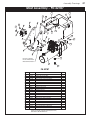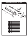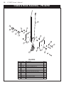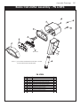
1
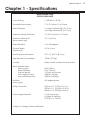
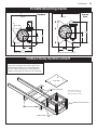
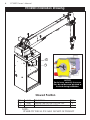
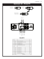
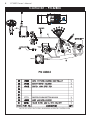
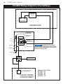
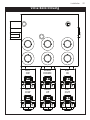
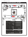
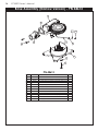
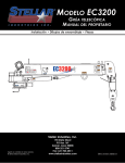
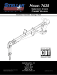
MODEL EC3200
TELESCOPIC CRANE
OWNERS’ MANUAL
Installation • Assembly Drawings • Parts
Reach in Feet/Meters
Capacity in Pounds/Kilograms
3025 lbs
1450 kg
1372 kg
16’2”
4.92 M
1550 lbs
15’
703 KG
3200 lbs
1450 kg
4.57 M
495 kg
2145 lbs
12’
3.66 M
45º
550 kg
1095 kg
780 lbs
353 kg
1900 lbs
862 kg
1710 lbs
6’
1.83 M
1085 lbs
492 kg
775 kg
3’
.914 M
1565 lbs
640 lbs
905 lbs
290 kg
410 kg
11’
3.35 M
15’
0’
4.57 M
Maximum 1 - part line capacity is
1600lbs (725kg). For greater loads,
use 2 - part line.
EC3200
EC
3200
DANGER
Electrocution Hazard
Death or serious injury will result from
inadequate clearance if crane, load,
or vehicle becomes electrically
charged.
• Maintain safe clearance from high
voltage power sources.
• Never approach vehicle or load if
equipment is near a high voltage
power source.
50
710 kg
7’
2.13 M
Weight of load handling devices are
part of the load lifted and must be
deducted from the capacity.
60
15º
6’
1.83 M
35234
1215 lbs
2415 lbs
30º
3’
.914 M
Proudly Designed
and Manufactured
in the USA by
0
80 7
1450 kg
9’
2.74 M
3200 lbs
60º
404 kg
675 kg
1450 kg
75º
890 lbs
1490 lbs
3200 lbs
83.69
0’
Angle Indicator
1090 lbs
1450 kg
973 kg
1450 kg
80º
40
30
20
C1179
PN 42817
10
0
13820
3200 lbs
3200 lbs
3200 lbs
EC3200
EC
3200
WARNING
Free Falling Boom Hazard
Free falling manual boom
extensions can result in death or
serious injury.
• Properly install retention pins
prior to operation.
• Do not stand in front of
extension when removing
retention pin.
• Do not allow extensions to
free fall.
12452
WARNING
Winch
WARNING
Boom
Exten
Pull
Boom
Down
ding
Fall Hazard
Hoisting personnel on boom,
hook, load, or loadline can result
in death or serious injury.
42818
NOTICE
• Never use crane to hoist
personnel.
WARNING
• Never ride the boom, hook,
load, or any device attached
to crane boom or load line.
Misuse Hazard
Two blocking the crane can result in death
or serious injury.
Never allow the hook block to contact the
boom tip by hoisting up, extending or
lowering the boom.
12300
12451
Misuse Hazard
Do not use stow hook for any lifting applications.
Using the stow hook for anything other than hook
stowage can result in death or serious injury.
This crane has been designed and
manufactured to ASME/ANSI B30.22
and/or B30.5 specifications.
12924
24712
WARNING
Overload Hazard
overload condition
Bypassing the
the overload
by tampering with death or
in
device can result
serious injury.
with overload
Never tamper
28256
device.
NOTICE
Damage may occur if worm gear runs
dry. Keep worm gear lubricated with
Stellar® grease (PN 4460).
9188
GREASE every 3 months.
Apply 3 ‘pumps’ of EP2
(extreme pressure grease)
then rotate crane fully.
15171
LOAD BLOCK RATING
3 Tons
(2,721 KG)
SNATCH BLOCK WEIGHT: 15 LBS (6.80 KG)
42819
Stellar Industries, Inc.
Subject to Change without Notification.
© 2014 Stellar Industries, Inc.
190 State Street
PO Box 169
Garner, IA 50438
800-321-3741
Fax: 641-923-2811
www.stellarindustries.com
Last Revision: 07/30/14
EC3200 Manual Revisions
Date of Revision
March 25th, 2013
Sections Revised
Chapter 2: Installation
Chapter 4:
Replacement Parts
Description of Revision
Updated Control Kit, Wiring Diagrams, Decal Kits, and
Replacement Parts to reflect engineering changes.
Table of Contents
Table of Contents
Chapter 1 - Specifications . . . . . . . . . . . . . . . . . . . . . . . . . . 1
Capacity Chart - Decal PN 42817 . . . . . . . . . . . . . . . . . . 2
Chapter 2 - Installation . . . . . . . . . . . . . . . . . . . . . . . . . . . . . 3
Installation Overview . . . . . . . . . . . . . . . . . . . . . . . . . . . . . 4
Flatbed Body Reinforcement . . . . . . . . . . . . . . . . . . . . . . 5
EC3200 Mounting Detail . . . . . . . . . . . . . . . . . . . . . . . . . . 5
EC3200 Installation Drawing . . . . . . . . . . . . . . . . . . . . . . . 6
Hydraulic Kit - PN 42799. . . . . . . . . . . . . . . . . . . . . . . . . . . 7
Control Kit - PN 42804 . . . . . . . . . . . . . . . . . . . . . . . . . . . . 8
EC3200 Wiring Diagram (Two Battery) . . . . . . . . . . . . . . 9
EC3200 Wiring Diagram (One Battery) . . . . . . . . . . . . . 10
Valve Bank Drawing . . . . . . . . . . . . . . . . . . . . . . . . . . . . 11
Stability Procedure. . . . . . . . . . . . . . . . . . . . . . . . . . . . . . 12
Stability Capacity Chart . . . . . . . . . . . . . . . . . . . . . . . . . 13
Decal Kit Placement - PN 42816 . . . . . . . . . . . . . . . . . . 14
Chapter 3 - Assembly Drawings . . . . . . . . . . . . . . . . . . . . . 15
Base Assembly - PN 42525 . . . . . . . . . . . . . . . . . . . . . . . 15
Base Assembly (Narrow Version) - PN 44613. . . . . . . . . 16
Mast Assembly - PN 42787 . . . . . . . . . . . . . . . . . . . . . . . 17
Main Boom Assembly - PN 42512. . . . . . . . . . . . . . . . . . 18
Extension Boom Assembly - PN 42520 . . . . . . . . . . . . . . 19
Cable & Hook Assembly - PN 42781 . . . . . . . . . . . . . . . 20
Radio Transmitter Assembly - PN 67894. . . . . . . . . . . . . 21
Chapter 4 - Replacement Parts . . . . . . . . . . . . . . . . . . . . . 23
Find a Dealer Near You:
http://www.stellarindustries.com/pages/dist/distsearch.htm
For Technical Questions, Information, Parts, or Warranty, Call Toll-Free at
800-321-3741
Hours: Monday - Friday, 8:00 a.m. - 5:00 p.m. CST
Or email at the following addresses:
Technical Questions, and Information
Order Parts
Warranty Information
[email protected]
[email protected]
[email protected]
i
ii
EC3200 Owner’s Manual
About this manual
A copy of this manual is provided with every crane and can be found in the hard plastic
manual case that is installed on the chassis. A copy of this manual shall remain with the
crane at all times.
Throughout the manual, three signal words will be used to bring attention to important
items:
A NOTICE signal word indicates a practice not related to physical injury.
A WARNING signal word indicates a hazardous situation which, if not
avoided, could result in death or serious injury.
A DANGER signal word indicates a hazardous situation which, if not
avoided, will result in death or serious injury.
Information contained within this manual does not cover operation, maintenance, or
troubleshooting. Please refer to the General EC Series Crane Manual for details on these
items.
This manual is not binding. Stellar Industries, Inc. reserves the right to change, at any time,
any or all of the items, components, and parts deemed necessary for product
improvement or commercial/production purposes. This right is kept with no requirement or
obligation for immediate mandatory updating of this manual.
If more information is required or technical assistance is needed, or if you feel that any
part of this manual is unclear or incorrect, please contact the Stellar Customer Service
Department by phone at 800-321-3741 or email at [email protected].
Chapter 1 - Specifications
Crane Rating:
Specifications
Model EC3200 Crane
SPECIFICATION SHEET
Standard Boom Length:
Boom Extension:
Maximum Horizontal Reach:
Maximum Vertical Lift:
(from crane base)
11,500 ft-lb (1.59 TM)
7’ (2.13 m) from CL of Crane
1st stage: Hydraulic 48" (121.9 cm)
2nd stage: Manual 48" (121.9 cm)
15’ (4.57 m) from CL of Crane
16’ 2” (4.93 m)
Boom Elevation:
-5 to +80 degrees
Mounting Space Required:
18” x 15” (45.7 x 38.1 cm)
Controls:
Radio control standard for all functions.
Stowed Height:
(crane only)
Approximate Crane Weight:
Winch Specifications
Rope Length:
Rope Diameter:
Line pull speed:
Max. single part line:
Max. double part line:
Rotation:
(worm gear)
Lifting Capacities:
Power Supply Required:
*Subject to change without notification
24” (61.0 cm)
730 lbs (331 kg)
65 ft (19.8 m)
7/32" (.56 cm)
15 ft/min (4.6 m/min)
1600 lbs (725 kg)
3200 lbs (1450 kg)
410 degree power
1625 lbs @ 7’ (737 kg @ 2.1 m)
905 lbs @ 11’ (410 kg @ 3.35 m)
640 lbs @ 15’ (290 kg @ 4.6 m)
12 volt power unit
(2.0 gpm @ 2600 psi)
(7.57 lpm @ 179 bar)
1
2
EC3200 Owner’s Manual
Capacity Chart - Decal PN 42817
3200 lbs
Reach in Feet/Meters
Capacity in Pounds/Kilograms
3025 lbs
1450 kg
1372 kg
16’2”
4.92 M
1550 lbs
15’
703 KG
3200 lbs
3200 lbs
1450 kg
4.57 M
1090 lbs
1450 kg
495 kg
2145 lbs
12’
3.66 M
973 kg
3200 lbs
1450 kg
80º
3200 lbs
1450 kg
45º
9’
2.74 M
3200 lbs
60º
404 kg
675 kg
1450 kg
75º
890 lbs
1490 lbs
1215 lbs
2415 lbs
550 kg
1095 kg
353 kg
1900 lbs
862 kg
30º
1710 lbs
15º
0’
3’
.914 M
492 kg
775 kg
3’
.914 M
6’
7’
2.13 M
Weight of load handling devices are
part of the load lifted and must be
deducted from the capacity.
640 lbs
905 lbs
710 kg
1.83 M
6’
1.83 M
1085 lbs
1565 lbs
83.69
780 lbs
290 kg
410 kg
11’
3.35 M
15’
0’
4.57 M
Maximum 1 - part line capacity is
1600lbs (725kg). For greater loads,
use 2 - part line.
EC3200
EC
3200
PN 42817
Chapter 2 - Installation
Installation
3
General Installation
This chapter is designed to serve as a general guide for the installation of a Stellar EC3200
Crane on a Stellar Service Body. Each installation is considered unique so certain portions
of this chapter may or may not apply to your direct application. If a question should arise
during the installation process, please contact Stellar Customer Service at (800) 321 3741.
This crane is designed for use with a Stellar Service Body installed on a vehicle that meets
the minimum chassis requirements of the crane. It is the installer’s responsibility to assure
that the crane is mounted on a platform that will support the maximum crane rating of this
crane.
Do not install this crane on a body not capable of handling the loads
imposed on it. Failure to do so may result in serious injury or death.
When installing welder units to the service bodies, it is highly
recommended that a surge protector is installed on the chassis batteries to protect the
crane radio receiver, wiring and other electronic devices from an unexpected electrical
spike or surge. Failure to do so could result in extensive damage to the service body and
crane electrical circuit.
Installation Notice
According to Federal Law (49 cfr part 571), each final-stage manufacturer shall complete
the vehicle in such a manner that it conforms to the standards in effect on the date of
manufacture of the incomplete vehicle, the date of final completion, or a date between
those two dates. This requirement shall, however, be superseded by any conflicting
provisions of a standard that applies by its terms to vehicles manufactured in two or more
stages.
Therefore, the installer of Stellar cranes and bodies is considered one of the manufacturers
of the vehicle. As such a manufacturer, the installer is responsible for compliance with all
applicable federal and state regulations. They are required to certify that the vehicle is in
compliance with the Federal Motor Vehicle Safety Standards and other regulations issued
under the National Traffic and Motor Vehicle Safety Act.
Please reference the Code of Federal Regulations, title 49 - Transportation, Volume 5 (400999), for further information, or visit http://www.gpoaccess.gov/nara/index.html for the full
text of Code of Federal Regulations.
4
EC3200 Owner’s Manual
Installation Overview
1. Determine that the mounting location for the EC3200 crane is at least 18” x 15” (45.7 x 38.1 cm).
2. Use the detail on the following page to drill .938” diameter holes into the mounting plate. Run tap on the
threads of the base to be sure they are clean.
3. Use a crane or lifting device capable of lifting the weight of the Stellar crane. The Stellar EC3200 weighs
approximately 800 lbs (360 kg). Note: cranes are shipped with rotation positioned at 180 degrees from
normal stowed travel position. This will allow for easy installation of the crane and permanent connection
of all hydraulic and electrical components prior to repositioning into the crane saddle.
4. Connect straps or chain from the lifting device to the main boom of the Stellar EC3200.
5. Use four (4) 7⁄8” x 2” Grade 9 bolts and four (4) 7⁄8” Grade 9 flat washers.
6. Install a washer on each bolt.
7. Apply Loctite Thread locker #277 to the bolts.
8. Using the lifting device, lower the Stellar EC3200 just above the crane compartment and start the bolts.
Have someone assist in leveling the crane.
9. Secure the crane using the mounting hardware provided. Note: longer or shorter bolts may be required –
recommended thread engagement into crane base is 0.75” – use grade 9, zinc plated bolts only.
10. Torque the bolts to 454 ft-lbs.
11. Remove supporting crane.
12. Hook-up hydraulics and electrical using the schematics provided at the end of this chapter.
Note: If questions should arise during any portion of this installation,
please contact Stellar Customer Service at (800) 321-3741.
k
ruc
T
f
to
n
o
Fr
Installation
EC3200 Mounting Detail
Standard
Narrow
Base
FRONT
FRONT
3.00
14.75
10.00
7.38
5.00
7.38
5.00
10.00
14.75
HOLE MOUNTING DETAIL
HOLE MOUNTING DETAIL
Flatbed Body Reinforcement
If it has been determined that the destination
body won’t support the crane with a fully
rated load, the body must be reinforced.
Use 1/4” fillet welds and an AWS qualified
welder to proceed as shown in this drawing:
3/8 PLATE
TUBE 4X2X0.38
Note: Tubing must be
at least 4” x 2” x 0.38”
(Except where noted)
TUBE 2X2X0.38(TYP 4)
TRUCK FRAME
TUBE 4X2X0.38
5
6
EC3200 Owner’s Manual
EC3200 Installation Drawing
2
3
NOTICE!
Route hoses correctly to ensure
they do not become pinched or
crushed during installation.
Stowed Position
ITEM
2
3
P ART
18041
51377
D E SC R I P T I O N
WASHER 0.88 SAE FLAT YELLOW GR9
CAP SCR 0.88-9X2.00 HHGR9
Q T Y.
4
4
NOTE:
STABILITY DECAL P/N 16881 IS PART OF THIS KIT
Installation
Hydraulic Kit - PN 42799
12 10
11
ROTATION CCW
BOOM DOWN
ROTATION
BOOM UP
ROTATION CW
MAIN
11
12 10
13
14
11
EXTENSION RETRACT
EXTENSION EXTEND
EXT
11
EXT OUT
EXT IN
04
05
12
12
12
12
12
12
02
06
07
03
MAIN UP
ROTATION CCW
ROTATION CW
MAIN DOWN
PN 42799
16
15
14
3861
13
49315
12
C4922
FTG ML FM O'RING 90 DEG
SWITCH PRES OVERLD CD-11C-2900R/WD
1
1
FTG ADAPT 4-6 F5OLO-S
8
11
D1291
FTG ADAPT 4-F5OLO-S
4
10
C1111
FTG ADAPT MSTR/FSTR 10-6 F5OG5
2
07
42984
HOSE-HYD .25X 43
1ref
06
42982
HOSE-HYD .25 X 42
1ref
05
43847
HOSE-HYD .25 X 20
1ref
04
42981
HOSE-HYD .25 X 19
1ref
03
42983
HOSE-HYD .25 X 23
1ref
02
42980
HOSE-HYD .25 X 22
1ref
01
42800
HOSE KIT 3315 CRANE (incl:2-11)
ITEM
PART No.
09
08
DESCRIPTION
1
QTY
7
EC3200 Owner’s Manual
Control Kit - PN 42804
Power
Unit
POWER
GROUND
OPT1
OPT2
8
Winch
PN 42804
17771
SWITCH PUSH BUTTON 9216-03
NOTE: P/N 47092 INCLUDES HARNESS & WINCH CONTROLLER
EC3200 Wiring Diagram (Two Battery)
FUSE 250 AMP
PN 36436
Installation
MASTER
SWITCH
250 AMP
Holder: PN 32523
(STELLAR SUPPLIED)
-
+
(NOT SUPPLIED)
TRUCK BATTERY
UNDERHOOD
CRANE HARNESS
CRANE
START MOTOR
SOLENOID
FUSE 250 AMP
PN 36436
OPT1
Holder: PN 32523
Torque Spec
Large Nuts: 35 in-lbs
Small Nuts: 15 in-lbs
OPT2
(STELLAR SUPPLIED)
GROUND
GROUND
GROUND POST
POWER
-
+
AUX BATTERY
GROUND
LOCATE AUX BATTERY AS
CLOSE TO CRANE AS POSSIBLE
87
SAFETY BRAKE
87A
86
30
SWITCH
POWER
10 AMP
85
POWER SOURCE FOR
RADIO REMOTE
CAB OR CRANE
COMPARTMENT
NOTICE
Operating the crane without
the truck engine running could allow the truck
battery to be discharged below levels required
for starter cranking power.
Minimum Wire Sizes:
EC3200 - #2
EC4000 - #2
EC5000 - #2
EC6000 - 1/0
9
10
EC3200 Owner’s Manual
EC3200 Wiring Diagram (One Battery)
FUSE 250 AMP
PN 36436
Holder: PN 32523
(STELLAR SUPPLIED)
-
+
TRUCK BATTERY
UNDERHOOD
CRANE HARNESS
CRANE
START MOTOR
SOLENOID
OPT1
Torque Spec
Large Nuts: 35 in-lbs
Small Nuts: 15 in-lbs
OPT2
GROUND
GROUND
GROUND POST
POWER
NOTICE
Operating the crane without
the truck engine running could allow the truck
battery to be discharged below levels required
for starter cranking power.
GROUND
87
SAFETY BRAKE
87A
86
30
SWITCH
POWER
10 AMP
85
POWER SOURCE FOR
RADIO REMOTE
CAB OR CRANE
COMPARTMENT
Minimum Wire Sizes:
EC3200 - #2
EC4000 - #2
EC5000 - #2
EC6000 - 1/0
Installation
Valve Bank Drawing
ROT
CW
INNER
DOWN
EXT
IN
ROT
CCW
INNER
UP
EXT
OUT
11
12
EC3200 Owner’s Manual
Stability Procedure
Definition of Stability for the Stellar Telescopic Crane Products:
A truck is stable until the load cannot be lifted off the ground with the winch, without
tipping over the truck. Every Stellar crane installed must be tested for stability to
determine the actual load capacity of the final truck package. The actual test data
must be recorded and supplied with the truck at the time of in-service and should be kept
with the truck at all times. The following procedure will test the truck package for stability
and will provide a stability capacity chart. The load limit information shown on the
stability capacity chart is formulated on 85% tipping.
Set Up:
1. Locate the truck on a test course in position for loading and engage travel brakes.
2. Set stabilizers so that they make contact with firm, level footings.
3. Operate the crane under partial load to assure operator proficiency and proper
machine function.
EC3200 Stability Data
Max Horizontal Reach: 180” (From the center of rotation to boom tip)
Stability Test Weight: 755 lbs.
Test Procedure
1. Rotate the crane into Zone 1 position.
2. With the crane fully retracted and the boom horizontal, winch the test weight off the
ground. Note: Keep weight within six inches of the ground at all times.
3. Extend the boom outward until full extension has been reached or until the truck
becomes unstable (Again, use the winch to keep the weight within six inches of the
ground.)
4. If the boom goes full extension without becoming unstable, the crane is termed stable
for this zone and 100% can be written in the Zone 1 data box.
5. If the truck becomes unstable prior to going full extension, retract the boom until the
truck becomes stable and measure the horizontal reach in this position (center of
rotation to boom tip). This is the stable horizontal reach for this zone. Stable horizontal
reach divided by Maximum horizontal reach multiplied by 100 equals the percentage
of rated capacity for this zone. Use the following formula to determine the percentage
of rated capacity:
6. Record this number in the data box for Zone 1. This is the revised capacity due to
stability for this zone.
7. Repeat this procedure for each zone until the worksheet is completed.
8. This is the revised capacity based on stability of this package.
Stability Capacity Chart
STABILITY CAPACITY CHART
Installation
13
EC3200 Owner’s Manual
Decal Kit Placement - PN 42816
14
3200 lbs
13
Reach in Feet
Feet/Meters
t/Meters
Capacity
Pounds/Kilograms
Capacit
ty in Pounds/
Kilograms
3025 lbs
1450
1450 kg
g
4
4.92
.92 M
1550 lbs
495
495 kg
g
3.66 M
3.66
973
973 kg
890 lbs
1490 lbs
404
404 kg
675 kg
g
675
9’
1450
1450 kg
g
45º
550
5
50 kg
1
095 kg
g
1095
780 lbs
353
353 kg
1900 lbs
862
8
62 kg
30º
775
775 kg
g
290
290 kg
0’
15’’
15
4
4.57
.57 M
Maximum
Maximum 1 - part li
line
ne ca
capacity
pacity is
eater loads,
loa
16
60
00lbs (7
25kg).
k . For gr
ads,,
1600lbs
(725kg).
greater
part li
ne.
use 2 - part
line.
EC3200
200
00
0
D
Death
eath o
or seri
serious
ous inj
injury
ury wi
w
will
ill resul
result
ult from
ina
d
dequate
clearance ifif crane,
crane, load,
load,
inadequate
clearance
or vehic
le becomes
becomes electrica
ally
ly
vehicle
electrically
charged.
• Maintain sa
fe cl
earance from high
safe
clearance
voltage pow
er
e sources.
power
•N
ever
e
approac
h vehicl
ehicle or lload
oad if
Never
approach
vehicle
s near a hi
gh voltage
equipmen
nt iis
equipment
high
pow
er source
e.
power
source.
18
50
410
410 kg
11
11’’
.35 M
3
3.35
El
Electrocution
ectrocution Ha
Hazard
zard
640 lbs
905 lbs
710
710 kg
7’
2.13
2.13 M
evices a
re
W
Weight
eight of load hand
handling
ling d
devices
are
of the
the loa
d lifted and mu
ust
st b
part of
load
must
be
e
deducted
capacity.
deducted ffrom
rom the capa
city
ity.
60
3’
.91
.914
4M
1565 lbs
6’
1.83
1
.8
83 M
DANGER
492
4
92 kg
1710 lbs
3’
.914
.914 M
6’
1
1.83
.83 M
1085 lbs
15º
8 .
83.69
0’
35234
35234
1215 lbs
2415 lbs
60º
Proudly Designed
a d Manufactured
and
in the USA by
70
80 70
.74 M
2
2.74
3200 lbs
75º
Angle Indicator
12
12’’
2145 lbs
1450 kg
1450
EEC3200
C3200
32
200
00
0
4.5 M
4.57
1090 lbs
1450
1450 kg
3200 lbs
15
15
15’’
703
703 KG
KG
3200 lbs
1450
1450 kg
1450
1450 kg
g
80º
06
16’2”
16’2
2”
1
372 kg
1372
3200 lbs
3200 lbs
40
30
20
10
0
1382
13820
0
Free
Fr
ee Falling
Falling Boom Hazard
falling manual
manual boom
boom
Free falling
death or
or
result in death
extensions can
extensions
serious injury.
injury.
serious
Properly install
install retention
retention pins
pins
• Properly
operation.
prior to operation.
stand in front
front of
of
• Do
Do not
not stand
exte
nsion when
when removing
removing
extension
rete
ntion pin.
pin.
retention
• Do
Do not
not allow extensions
extensi
sio
ons to
free fall.
12452
12452
W
WARNING
ARNING
Pull
Pull
nchh
inc
Winch
W
WARNING
WARNING
10
03
42818
WARNING
WARNING
C1179
C1179
PN 42817
42817
02
W
WARNING
ARNING
04
oom
Boom
B
Boom
Boom
Down
Down
n
ng
ding
ndi
teend
Exten
Ex
Fall Hazard
Hoi
Hoisting
sting personnel
personnel on boom,
boom,
hook
loadline can
can result
result
hook,, load
load,, or loadline
iin
n death or serious
serious injury.
injury
y.
Misuse
Mis
u Haz
use
Hazard
ard
Two bl
ocking the crane can
can result
result in death
Two
blocking
injury.
or serious injury.
• Neve
st
Neverr use crane to hoi
hoist
pers
onnel.
personnel.
N
ever allow
allow the hook block
block to
to ccontact
ontact the
Never
hoisting up, extending
extending or
boom tip by hoisting
low
we
ering the boom.
lowering
Never ride the b
oom, hook
• Never
boom,
hook,,
lload,
oad, o
ce a
ttached
orr any devi
device
attached
to ccrane
rane boom or lload
oad lline.
ine.
12
12300
300
12451
Misuse
Misuse Ha
Hazard
zard
12
NOTICE
any
Do not use
use stow hook
hook for an
y lifting applications.
This crane has been designed and
manufactured to ASM
ASME/ANSI
E/ANSI B30.22
and/or B30.5 specifications.
specifications.
12924
Using
anything
hook
Us
ing the stow hook for an
ything other than ho
ok
stowage
injury.
stowage ccan
an result
result in death or serious injury
y.
24712
24712
08
G
ARNING
WARNIN
W
Overload
Overload Hazard
on
dittio
d
nd
on
verrload ccondition
overload
eo
the
ypassing th
B
Bypassing
a
verload
overload
eo
the
ith th
with
pering w
ampe
by ttampering
by
orr
th o
ath
ea
death
esult in de
e
n rresult
can
evvice ca
e
d
device
njury.
ous iinjury.
erio
sserious
erload
ve
overload
iti h o
with
er w
pe
tamper
evver ta
Ne
Never
8256
2
28256
evice.
de
device.
07
GREASE
GREASE every 3 months.
Apply 3 ‘pumps’ of EP2
Apply
(extreme pressure grease)
fully.
then rotate crane fully.
Crane Compartment Inner Door
Suggested Placement
15
15171
171
21
14
FOR SERVICE
SERVICE O
ON
N THIS EQUIP
EQUIPMENT
MENT
CONT
TA
ACT:
CONTACT:
STELLAR
R INDUSTRIES,
INDUSTRIES,
IE INC
INC..
STATE STR
REET
EET, G
ARNER
N , IA 50438
190 STATE
STREET,
GARNER,
641-923-3741
800-321-3741
3200 lbs
R
Reach
each in Feet/Meters
Fee
et//Metterrs
Capacity
Ca
pacity in Pounds/Kilograms
Pounds/Kilogra
ogram
ms
3025 lbs
1450
1450 kg
kg
1
16’2”
6’2”
1372 k
g
1372
kg
4
4.92
.92 M
1550 lb
lbs
s
15’
1
5’
703
703 KG
KG
3200 lbs
3200 lbs
1450
1450 kg
kg
4214
4.5
4.57
57 M
1090 lbs
1450
1450 kg
kg
495
495 kg
kg
12’
1
2’
2
2145 lbs
3.66 M
3.66
973
973 kg
kg
3200
00 lbs
1450
1
450 kg
kg
W
WARNING
ARNING
22
80
80º
890 lb
s
lbs
1490 lb
lbs
s
3200 lb
lbs
bs
9
9’’
2
2.74
.74 M
3200 lb
lbs
bs
1450
1450 kg
kg
7
5º
75º
1215 lbs
2415
1 lbs
60
60ºº
45
5º
45º
550
550 k
kg
g
1095 kg
kg
1095
3’’
3
.9
.914
14 M
1565 lbs
6’’
6
1.83
1
.8
83 M
7
7’’
.13 M
2
2.13
640 lb
lbs
s
905 lb
lbs
s
710
710 k
kg
g
83.69
83.
3.69
3
3’’
.9
.914
14 M
6
6’’
492
492 kg
kg
775
775 kg
kg
Weight
Weight of lload
oad ha
handling
nd
dling de
devices
vices ar
are
re
part
art of
of the load
loa
ad lifted
llifted
d and
d must
must be
be
d
e ucted from
ed
from the capacity.
capacity.
deducted
68024
1.8
1.83
83 M
1085 lbs
1710 lbs
15º
15
5º
0
0’’
Failure to follow operating,
maintenance, or safety
instructions can result in
injury..
death or serious injury
862
862 kg
kg
30
30ºº
Read and understand all
manuals and safety signs
before operating or servicing
this equipment.
equipment.
780 lb
lbs
bs
353
kg
353 k
g
1900 lb
lbs
s
Untrained Operator Hazard
16
404
404 k
kg
g
6
75 k
g
675
kg
1450
1450 kg
kg
2
290
90 kg
kg
410
410 k
kg
g
11’
11’
3.35
3.35 M
15’
15’
LOAD BLOCK RA
RATING
ATING
TING
0
0’’
3T
Tons
o
ons
4.57 M
4.57
Maximum
Maximum 1 - p
part
art lli
line
e capacity
capa
acity is
is
1600lbs
For
greater
1600l
lb
bs
s ((725kg).
725kg).. F
or g
reater
eater loads,
llo
oad
ds,
use 2 - p
part
art line.
line.
EEC3200
C3200
200
00
0
(2,721 KG)
SNATCH
SNAT
TCH BLOCK WEIGHT:
WEIGHT: 15
15 LBS (6.80 KG)
42
42819
819
PN 42817
DANGER
El
Electrocution
ectrocution Ha
Hazard
zard
Death or serious injury will
result from ttouching
ouching ttethered
ethered
remote if ccrane,
rane, load, or
or vehicle
vehicle
electrically
becomes elect
rically charged.
Maintain safe cclearance
learance from
from
high voltage power sources.
4186
4186
19
WARNING
WARNING
Overload
Overload Hazard
Hazard
Do not exceed
exceed equipment
equipment load
load charts
charts and ratings.
ratings.
Failure to follow equipment
equipment load ccharts
harts and ratings
ratiin
ngs
can result in death
death or
or serious
serious injury.
injury.
4189
4189
20
17
15
PULL
PUSH PULL
EXTENSION
EXTENSION
IN
42818
0 10 20
30
ROT
ROTATION
ATION
CW
11
40
Movement
Movement Hazard
Hazard
Af
After
ter stow
stowing
ing the crane, alw
always
ays return the va
valve
alve
lve
bank manu
al overrides to the neutral position.
posiition.
tion.
manual
Failure
Failure to return the
the manual
manual overrides to the neutral
position
position can result
result in
in death or
or serious
serious injury.
injury
y.
25
25159
159
BUTTON
HOLD BUTT
ON TO
TO
OPERATE
OPERA
TE CRANE
MANUALLY.
MANUALLY.
09
Kit PN 42816
(Rev D - 11/22/13)
For use with Crane Package
PN
9188
12300
12451
12452
13819
13820
15171
15172
18472
24712
25159
28256
35234
42817
42818
42819
42820
C1179
DESCRIPTION
ROTATE/GREASE
DECAL RO
TA
ATE/GREASE
WARNING
DECAL W
ARNING TWO BLOCKING
WARNING
DECAL W
ARNING HOISTING PERSONNEL
WARNING
DECAL W
ARNING MANUAL EXT
INDICATOR
DECAL ANGLE INDIC
ATO
TOR SS
INDICATOR
DECAL ANGLE INDIC
ATO
TOR CS
DECAL GREASE WORM
DECAL ASME/ANSI B30.22/B30.5
OPERATION
DECAL MANUAL OPER
ATTTION
WARNING
ARNING STOW HOOK
DECAL W
WARNING
ARNING MANUAL OVERRIDES
DECAL W
WARNING
DECAL W
ARNING OVERLOAD DEVICE
DECAL STELLAR MADE IN THE USA
CAPACITY
DECAL CA
PACITY EC3200
IDENTIFICATION
DECAL IDENTIFIC
ATION EC3200
E
SNATCH
DECAL SN
ATCH BLOCK 3 TON
DECAL VB CONTROL ECSERIES
DECAL DANGER ELECTROCUTION SMALL
LOCATION
Crane Base
Crane Horse Head
Main Boom
Main Boom
Main Boom
Main Boom
Crane Base
Main Boom
On top of valve bank
Crane Boom above stow hook
Valve
Valve Bank
Main Cylinder
Main Boom
Main Boom and Crane Compartment
Main Boom (Both Sides)
Snatch Block
On top of valve bank
Main Boom
QTY
1
1
1
1
1
1
1
1
1
1
1
1
1
2
2
1
1
1
LOCATION
Crane Compartment
Crane Compartment
Crane Compartment
Crane Compartment
Four corners
corners of the body/chassis
Suggested: Rear body/tailgate
Suggested: Side corners of body
QTY
1
1
1
1
4
1
3
For use with Body/Chassis Package
ITEM
19
20
21
22
23*
24*
25*
PN
4186
4189
4214
68024
C4545
C5910
C5911
*Not Shown
DESCRIPTION
DECAL DANGER ELECTROCUTION REMOTE
WARNING
ARNING OVERLOAD
DECAL W
SERVICE
DECAL SE
RVICE
WARNING
OPERATOR
ARNING UNTRAINED OPER
ATOR
DECAL W
DECAL DANGER ELECTROCUTION LARGE
DECAL STELLAR 4x9.5
DECAL STELLAR 2x4.5
CCW
42
42820
820
WARNING
WARNING
ITEM
01
02
03
04
05
06
07
08
09
10
11
12
13
14
15
16
17
18
OUT
MAIN
DOWN UP
13819
EEC3200
C32
C3200
200
00
0
05
Angle Indi
Indicator
cator
70
70
80
NOTICE
NOTI
CE
60
01
occur
Damage may oc
cur if worm gear runs
dry.. Keep worm gear lubr
lubricated
dry
icated with
Stellar® grease (PN 4460).
9188
50
14
18472
18
472
Assembly Drawings
Chapter 3 - Assembly Drawings
Base Assembly - PN 42525
4
5
2
3
9
7
10
12
9
11
1
8
6
PN 42525
ITEM
1
2
3
4
5
6
7
8
9
10
11
12
PART
42784
41640
62487
21151
D1307
30750
42 7 95
D0 7 9 0
D1345
D1810
C22 5 6
56589
DESC RIPT ION
BA SE E C 3 2 0 0
BEARING SWING DRIVE 170-00058-1
MOTOR 80CC EC3200 YMPH-80-H2(R)-K-S-B
GASKET MOTOR 008-10056-1
C A P S C R 0 .5 0-13 X 1 .2 5 S H
CAP SCR 0.50-13X3.50 HHGR8
S TOP S L I DIN G E C 3 200
WASHER 0.50 FLAT GR8
FTG CPRSN 0.12NPT/0.25 TUBE
TBE AIR SAEJ844 TYPE A .25 (RM)
F TG C O U P L E R P I P E 0 . 13
ZERK 1/8 NPT STRAIGHT LONG THREAD
QTY.
1
1
1
1 ref
2
13
1
13
2
1
1
1
15
16
EC3200 Owner’s Manual
Base Assembly (Narrow Version) - PN 44613
2
4
11 12
7
10
3
5
8
6
PN 44613
I TE M
1
2
3
4
5
6
7
8
9
10
11
12
PART
44614
41640
62487
21151
D1307
30750
4 2 795
D0 7 9 0
D1345
D1810
C225 6
56589
D E SCRI P T I ON
Q T Y.
BASE EC3200 NARROW
1
BEARING SWING DRIVE 170-00058-1
1
MOTOR 80CC EC3200 YMPH-80-H2(R)-K-S-B 1
GASKET MOTOR 008-10056-1
1 ref
CAP SCR 0.50-13X1.25 SH
2
CAP SCR 0.50-13X3.50 HHGR8
13
S T OP S L ID I N G E C 3 2 00
1
WASHER 0.50 FLAT GR8
13
FTG CPRSN 0.12NPT/0.25 TUBE
2
TBE AIR SAEJ844 TYPE A .25 (RM)
1
F TG C OU P LE R P I P E 0 .13
1
ZERK 1/8 NPT STRAIGHT LONG THREAD
1
9
1
Assembly Drawings
Mast Assembly - PN 42787
14
16
5
10
9
23
15
1
9
10
9
22
20
9
21
9
6
4
15
8
7
16
11
13
12
3
3
18
P/N 43579 MUST
GO IN THIS MAST
MOUNTING HOLE
2
19
PN 42787
ITEM
1
2
3
4
5
6
7
8
9
10
11
12
13
14
15
16
18
19
20
21
22
23
PA RT
42318
42513
42788
42789
2 0 3 62
0345
0346
047 9
D0 9 1 7
0478
0340
43579
47411
44475
0343
0420
58 70
0492
51896
30659
C6021
C6022
D E SCR IPTION
MAST EC3200
POWER UNIT 12V EC3200
WASHER 0.44 SAE FLAT YELLOW GR8
CAP SCR 0.44-14X2.25 HHGR8 ZY
BUSHING IGU S GFI -161 8-0 8
CAP SCR 0.38-16X1.50 HHGR5
WASHER 0 .38 FLAT
C A P S C R 0 . 25 - 20 X0 . 7 5 H HG R 5
WAS H ER 0.25 FL AT SS
CA P S CR 0 . 25 - 2 0 X0 .5 0 H H GR5
WASHER 0.25 FLAT
CAP SCR 0.44-14X2.75 MOD EC3200
BRKT OVERRIDE BUTTON EC3200
C O V E R E C 3 2 0 0 H D PE
W A S HE R 0.31 U S S F L AT Z IN C
CAP SCR 0.31-18X0.7 5 HHGR5
W ASH ER 0 . 38 STAR E XTERN A L
CAP S CR 0.38-16 X0. 75 HHGR5
B R K T C O V E R EC C R A N ES
N U T 0 . 2 5 - 2 0 H H N Y L OC S S
CAP SCR 0.25-20X0.75 BTNHD SS
CAP SCR 0.25-20X1.00 BTNHD SS
NOTE: WINCH CONTROLLER(P/N 42821)
SHOWN FOR REFERENCE
Q TY.
1
1
8
7
4
2
2
2
5
2
2
1
1
1
3
3
1
1
1
1
1
1
17
18
EC3200 Owner’s Manual
Main Boom Assembly - PN 42512
MOUNTING HARDWARE WILL
BE PART OF THE WINCH PACKAGE.
USE ALL HARDWARE, EXCEPT BOLTS.
2
23
25
24
21
4
6
7
16
12
15
6
27
28
4
26
28
17
24
16
3
11
4
1
9 10
27
5
16
28
13
15
28
27
16
14
8
18
20
19
PN 42512
ITEM
1
2
3
4
5
6
7
8
9
10
11
12
13
14
15
16
17
18
19
20
21
22
23
24
25
26
27
28
PART
42303
41641
72602
0340
C5606
43845
c1592
42508
D0 7 9 0
13815PC
C6106
00 69
20362
42503
42515ZP
9320
42516ZP
42517ZP
5591
21170
0345
34103
D0917
0479
0521
C0081
C6353
9843
D E SCRI PTION
I N NE R B OO M E C 3 2 00
WINCH DC2000 WARN 63899
CORD REEL ASM 15/21 FT CRANE
WASHER 0.25 FLAT
CLAMP 0.25 BLK VINYL
CAP SCR 0.25-20X0.38 HHGR5
ZERK 1/8 NPT STRAIGHT
WEAR PAD 0.50X1.50X2.00
WASHER 0.50 FLAT GR8
PLATE ANGLE INDICATOR
NUT 0.50-13 HHGR5 NYLOC
BUSHING QSI-1618-16
BUSHING BPC16DXR08 1.00X.50
CYLINDER 3.00X13.00 EC3200
PIN 1.00X6.38 D&T
PIN CAP 0.44X1.75X0.19 SS
PIN 1.00X5.13 D&T
PIN TEAR DROP 1.00X2.19
WASHER 0.31 SAE FLAT YELLOW GR8
CAP SCR 0.31-18X1.00 HHGR8
CAP SCR 0.38-16X1.50 HHGR5
RECEIVER RADIO CONTROL 6 FCTN H2
W AS HE R 0 .2 5 F LA T S S
CAP SCR 0.25-20X0.75 HHGR5
WASHER 0.25 LOCK
CLAMP 0.50 BLK VINYL
WASHER 0.38 SAE FLAT YELLOW GR8
CAP SCR 0.38-16X0.75 HHGR8
QTY.
1
1
1
3
1
2
1
1
4
2
2
2
1
1
2
6
1
1
1
1
4
1
2
3
2
1
6
6
Assembly Drawings
Extension Boom Assembly - PN 42520
19
5
6
12
10
11
1
12
11
9
20
18
2
15
22
8
17
7
5
3
3
14
8
15
16
3
16
19
4
21
3
13
PN 42520
ITEM
1
2
3
4
5
6
7
8
9
10
11
12
13
14
15
16
17
18
19
20
21
22
PA R T
42311
42 507
D0790
10172
42509
42312
42978PC
42977
42317
42524ZP
0423
37824
0507
27710
C6106
0352
35105
D0178
0505
D0561
42505PC
43846
D E S C RI P T I O N
EXT BOOM 1ST EC3200
CY LINDER 1 . 50X48. 00
WASHER 0.50 FLAT GR8
CAP SCR 0.50-13X1.00 HHGR8 ZY
WEAR PAD 0.38X1.38X1.50
EXT BOOM 2ND EC3200
FLAT BOOM STOP EC3200
P IN HIT CH 0 .6 3 X4 .0 0
SHEAVE EC3200 5.00 DIA .22R/1.00THK
P IN 0.75X2.50 COTTER
MACHY WASHER 0.75ID 10GA
C O T T E R P I N . 1 25X1 .00
CAP SCR 0.50-13X4.50 HHGR5
SPRING ANTI 2 BLOCK SUMMIT
NUT 0.50-13 HHGR5 NYLOC
WASHER 0.50 USS FLAT ZINC
SWITCH LIMIT E1117-B9111-6C
WASHER #10 SAE FLAT ZINC
CAP SCR 0.50-13X3.50 HHGR5
CAP SCR 0.25-20X0.50 BTNHD SS
PLATE CRADDLE EC3200
SCREW #10-24X0.38 SH SS
QTY.
1
1
9
1
2
1
1
2
2
2
4
4
2
2
3
2
1
2
1
2
1
2
20
EC3200 Owner’s Manual
Cable & Hook Assembly - PN 42781
8
13
3
4
11
12
11
13
2
5
1
3
1
7
6
10
9
PN 42781
ITEM
1
2
3
4
5
6
7
8
9
10
11
12
13
PART
42523PC
42317
0352
5468
27810
16607PC
47868
42316
9263
C6018
0375
42524ZP
37824
DE SC RI PTION
PLATE SNATCH BLOCK EC3200
SHEAVE EC3200 5.00 DIA .22R/1.00THK
WASHER 0.50 USS FLAT ZINC
NUT 0.50-13 HHGR8 NYLOC
SPACER 3315 SNATCH BLOCK UHMW
SPACER 3315 SNATCH BLOCK
CAP SCR 0.50-13X2.75 HHGR8
WIRE ROPE 7/32 7X19 GAC 65FT
PIN .38X3.00 QUICK RELEASE
HOOK CRANE-3 TON
MACHY WASHER 0.75ID 14GA
P IN 0.75X2.50 CO TTER
COTTER PIN .125X1.00
QTY.
2
1
6
3
2
1
3
1
1
1
2
1
2
Assembly Drawings
Radio Transmitter Assembly - PN 67894
9
1
10
2
6
7
3
4
SEE NOTE
8
11
NOTE: 1) P/N'S 25999 & 24958 ARE OPTIONAL COVERS
FOR THE SWITCHES AND TRIGGER
5
PN 67894
I TEM
1
2
3
4
5
6
7
8
9
10
11
PART
20088
51830
24385
22600
35441
16975
51831
38475
36156
29460
50932
21
DESCRIPTI ON
Q TY.
CONTROL HANDLE HOUSING 4 FCTN HET
1
CONTROL HANDLE FACE PLT 5 FCTN
1
GUARD RADIO SWITCH 4 FCTN
1
SWITCH TOGGLE HET RADIO 63019300
5
BATTERY TUBE AA HETRONIC RADIO
1
SWITCH E STOP ASM HETRONIC RADIO
1
DECAL CONTROL HANDLE 5 FCTN
1
SCREW 4MMX12MM PHMS PH
4
SCREW 4MMX14MM PHMS PH
2
SCREW 3MMX35MM PHMS PH
2
CONTROL HANDLE GRIP LESS TRIGGER HET H2
1
22
EC3200 Owner’s Manual
This page intentionally left blank.
Replacement Parts
Chapter 4 - Replacement Parts
HYDRAULIC COMPONENTS
PART#
DESCRIPTION
42840 HYDRAULIC SWING MOTOR
21151
GASKET - HYDRAULIC SWING MOTOR
42513 POWER UNIT 12V EC3200
44028 VALVE CARTRIDGE - POWER UNIT 12V #19012-D
44027 VALVE COIL - POWER UNIT 12V #11494-D
44029 MOTOR 12V - POWER UNIT #08111-1
44030 12V SOLENOID (12volt hydraulic system) #17757
44026 HYDRAULIC RESERVOIR - POWER UNIT 12V #14071
44025 FILL CAP - HYDRAULIC RESERVOIR
9803
C-BALANCE VALVE
43892 SEAL KIT - MAIN LIFT CYLINDER
43893 SEAL KIT - EXTENSION CYLINDER
49315 PRESSURE SWITCH
42821 CONTROLLER SOLENOID
C2027 O'RING - # 4 FACE SEAL
C2028 O'RING - # 6 FACE SEAL
D1245 O'RING - # 4 SAE
D1246 O'RING - # 6 SAE
ASSEMBLY COMPONENTS
44375 WORM GEAR - ROTATION BEARING
44383 BEARING & SEAL KIT - ROTATION BEARING
44376 BEARING RETAINER - ROTATION BEARING
44377 ADAPTER HOUSING - HYDRAULIC MOTOR
20362 BUSHING 1.00" X 0.50"
0069
BUSHING 1.00" X 1.00"
42508 WEAR PAD 0.38" X 1.50" X 2.00"
42509 WEAR PAD 0.38" X 1.38" X 1.50"
42978 BOOM STOP FLAT
9320
PIN CAP 0.44" X 1.75" X 0.25" SS
C6353 WASHER 0.38 FLAT GR8
13573 CAP SCR. 0.38-16 X 1.00" GR8
0375
MACHINE WASHER -0.75" ID 14GA.
0423
MACHINE WASHER -0.75" ID 10GA.
42317 SHEAVE
42316 WIRE ROPE
42977 HITCH PIN 0.63" X 4.00"
9263
QUICK RELEASE PIN .38 X 3.00"
42505PC CRADLE PLATE
27710 SPRING ANTI-2-BLOCK
C6018 HOOK 3-TON
10709 SAFETY LATCH FOR 3 TON HOOK - Campbell
51330 SAFETY LATCH FOR 3 TON HOOK - Crosby
C1592 GREASE ZERK
ELECTRICAL COMPONENTS
35105 LIMIT SWITCH
11544
CORD REEL
17771 PUSH BUTTON (12volt hydraulic system)
47410 MOMENTARY SWITCH
41641 WINCH
28978 BOSCH RELAY
36436 FUSE 250 AMP
RADIO REMOTE COMPONENTS
39784 RADIO REMOTE SYSTEM
50932 HANDLE ASM
16975 E-STOP SWITCH
22600 TOGGLE SWITCH
20088 LOWER TRANSMITTER HOUSING
35441 BATTERY TUBE HOLDER
35916 BACK UP CORD
23
Limited Warranty Statement
Stellar Industries, Inc. (Stellar) warrants products designed and manufactured by Stellar to be free from defects in material and workmanship under
proper use and maintenance. Products must be installed and operated in accordance with Stellar’s written instructions and capacities. This warranty
shall cover the following:
Stellar Cranes, Stellar Hooklift Hoists, Stellar Cable Hoists, Stellar Container Carriers, Stellar Service Trucks, and Stellar X-Tra-Lift Systems:
Twelve (12) month warranty on parts from the date recorded by Stellar as the in-service date, not to extend beyond twenty-four (24) months from date
of manufacture,
Twelve (12) month repair labor from the date recorded by Stellar as the in-service date, not to extend beyond twenty-four (24) month from date of
manufacture, and
Thirty-six (36) month warranty on all Stellar Manufactured structural parts from the date recorded by Stellar as the in-service date, not to extend beyond
forty-eight (48) months from date of manufacture.
Stellar Tarper Systems:
Twelve (12) month warranty on parts from the date recorded by Stellar as the in-service date, not to extend beyond twenty-four (24) months from date
of manufacture and
Three (3) month repair labor from the date recorded by Stellar as the in-service date, not to extend beyond fifteen (15) month from date of
manufacture.
The in-service date will be derived from the completed warranty registration card. In the event a warranty registration card is not received by Stellar, the
factory ship date will be used.
Stellar’s obligation under this warranty is limited to, and the sole remedy for any such defect shall be, the repair and/or replacement (at Stellar’s option)
of the unaltered part and/or component in question. Stellar after-sales service personnel must be notified by telephone, fax, or letter of any warrantyapplicable damage within fourteen (14) days of its occurrence. If at all possible, Stellar will ship the replacement part within 24-hours of notification by
the most economical, yet expedient, means possible. Expedited freight delivery will be at the expense of the owner.
Warranty claims must be submitted and shall be processed in accordance with Stellar’s established warranty claim procedure. Stellar after-sales service
personnel must be contacted prior to any warranty claim. A return materials authorization (RMA) account number must be issued to the claiming party
prior to the return of any warranty parts. Parts returned without prior authorization will not be recognized for warranty consideration. All damaged parts
must be returned to Stellar freight prepaid; freight collect returns will be refused. Freight reimbursement of returned parts will be considered as part of
the warranty claim.
Warranty service will be performed by any Stellar new equipment distributor, or by any Stellar-recognized service center authorized to service the type
of product involved, or by the Stellar factory in the event of a direct sale. At the time of requesting warranty service, the owner must present evidence
of date of delivery of the product. The owner shall be obligated to pay for any overtime labor requested of the servicing company by the owner, any
field service call charges, and any towing and/or transportation charges associated with moving the equipment to the designated repair/service
provider.
All obligations of Stellar and its authorized dealers and service providers shall be voided if someone other than an authorized Stellar dealer provides
other than routine maintenance service without prior written approval from Stellar. In the case repair work is performed on a Stellar-manufactured
product, original Stellar parts must be used to keep the warranty in force. The warranty may also be voided if the product is modified or altered in any
way not approved, in writing, by Stellar.
The owner/operator is responsible for furnishing proof of the date of original purchase of the Stellar product in question. Warranty registration is the
ultimate responsibility of the owner and may be accomplished by the completion and return of the Stellar product registration card provided with the
product. If the owner is not sure of registration, he is encouraged to contact Stellar at the address below to confirm registration of the product in
question. This warranty covers only defective material and workmanship. It does not cover depreciation or damage caused by normal wear and tear,
accident, mishap, untrained operators, or improper or unintended use. The owner has the obligation of performing routine care and maintenance
duties as stated in Stellar’s written instructions, recommendations, and specifications. Any damage resulting from owner/operator failure to perform such
duties shall void the coverage of this warranty. The owner will pay the cost of labor and supplies associated with routine maintenance.
The only remedies the owner has in connection with the breach or performance of any warranty on the Stellar product specified are those set above.
In no event will Stellar, the Stellar distributor/dealer, or any company affiliated with Stellar be liable for business interruptions, costs of delay, or for any
special, indirect, incidental, or consequential costs or damages. Such costs may include, but are not limited to, loss of time, loss of revenue, loss of use,
wages, salaries, commissions, lodging, meals, towing, hydraulic fluid, or any other incidental cost.
All products purchased by Stellar from outside vendors shall be covered by the warranty offered by that respective manufacturer only. Stellar does not
participate in, or obligate itself to, any such warranty.
Stellar reserves the right to make changes in design or improvement upon its products without imposing upon itself the same upon its products
theretofore manufactured.
This warranty will apply to all Stellar Cranes, Stellar Hooklift Hoists, Stellar Cable Hoists, Stellar Container Carriers, Stellar Service Trucks, Stellar X-Tra-Lift
Systems, and Stellar Tarper Systems shipped from Stellar’s factory after January 1st, 2010. The warranty is for the use of the original owner only and is not
transferable without prior written permission from Stellar.
THIS WARRANTY IS EXPRESSLY IN LIEU OF ANY OTHER WARRANTIES, EXPRESS OR IMPLIED, INCLUDING ANY WARRANTY OF MERCHANTABILITY OR FITNESS FOR
A PARTICULAR PURPOSE. REMEDIES UNDER THIS WARRANTY ARE LIMITED TO THE PROVISION OF MATERIAL AND SERVICES, AS SPECIFIED HEREIN. STELLAR
INDUSTRIES, INC. IS NOT RESPONSIBLE FOR INCIDENTAL OR CONSEQUENTIAL DAMAGES.
Revision Date: February 2010
Document Number: 37040