1
_R_'r=_rti_N°perat°r's
Manual
®
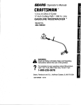
24cc/1.46
cu.in. 2-Cycle
17 Inch Cutting Path
GASOLINE WEEDWACKER
Model No.
358.796190
WARNING:
•Read and follow all Safety Rules and Operating
Instructions before first use of this product.
For answers to your questions about this product:
Call 7 am-7 pm, Mon-Sat; Sun, t0 am-7 pm
II
1-800-235-5878
Sears, Roebuck and Co., Hoffman Estates, IL 60179 USA
530087757
04/07'/99
Warranty Statement
Safety Rules
Assembly
Operation
Maintenance
Service & Adjustments
2
2
4
5
8
9
Storage
Troubleshooting Chart
Emissions Statement
Repair Parts Ust
Spanish
Parts and Ordedng
10
1
12
14
17
Back Cover
FULL ONE YEAR WARRANTY ON CRAFTSMAN GAS POWERED
WEEDWAGKER ® LINE TRIMMER
For one year from the date of purchase, when this Craftsman Gas Powered
Weedwacker® Line Trimmer is maintained, lubricated, and tuned up according to
the operating and maintenance instructions in the Operator's Manual, Sears will
repair, free of charge, any defect in materials or workmanship.
This warranty excludes nylon line, spark plug, and air filter, which are expendable
parts and become worn during normal use.
If this Weedwacker® Line Trimmer is used for commercial purposes, this warranty applies for only 90 days from the date of purchase. If this Weedwacker® Une
Trimmer is used for rental purposes, this warranty applies for only 30 days from
the date of purchase. This warranty applies only white this product is in use in the
United States,
WARRANTYSERVICE IS AVAILABLE BY RETURNINGTHE WFJEDWACKER®LINE
TRIMMERTO THE NEARESTSEARS SERVICE CENTER IN THE UNITEDSTATES.
This warranty gives you specific legal rights, and you may also have other dghts
which vary from state to state.
Sears, Roebuck and Co., 01817 WA Hoffman Estates, IL 60179
WARNING:
When using gardening
appliances, basic safety precautions
must always be followed to reduce the
risk of fire and serious injury. Read and
follow all instructions.
DANGER: Never use blades or flailing devices. This unit is designed for
line trimmer use only. Use of any other
accessories or attachroents will increase the risk of injury.
@@@
Thispower unit can be dangerous!
Operator is responsible for following
instructionsand warnings on unit and
in manual. Read entire Operator's
Manual before using unit! Be thorough.
ly familiar with the controls and the
proper use of the unit. Restrict the use
of this unit to persons who have read,
understand, and will follow the instructions and warnings on the unit and in
the manual. Never allow children to
operate this unit.
WARNING: Triromer llne throws objects violently. You and others can be
blinded/injured. Wear eye and leg
protection. Keep body pads clear of
rotating line. Keep children, bystanders, and animals 50 feet (15 ran)away.
If approached, stop unit imroediatety.
EyeProtection
Safety _nformation on the unit
2
• If situations occur which are not covered in this manual, use care and
good judgement. If you need assistance, contact Sears Service or call
the 1-800 number listed on the front of
this manual.
OPERATOR SAFETY
• Always wear safety eye protection;
• Always wear _ong pants, long
sleeves, boots, and gloves. Wearing
safety leg guards is recommended.
Do not go barefoot or wear sandals.
Stay clear of spinning line.
• Secure hair above shoulder length
Secure or remove loose clothing or
clothing with loosely hanging ties,
straps, tassels, etc. They can be
caught in moving parts.
• Do not operate when you are tired,
il!, or under the influence of alcohol,
drugs, or medication.
• Wear hearing protection if you use
unit for more than 1-1/2 hours per
day.
• Never start or run inside a closed
room or building. Breathing exhaust
fumes can kill.
• Keep handles free of oil and fuel.
UNIT / MAINTENANCE
SAFETY
• Disconnect the spark plug before
performing maintenance except carburetor adjustments.
• Look for and replace damaged or
loose parts before each use. Look
for and repair fuel leaks before use.
Keep in good working condition.
• Replace trimmer head parts that are
chipped, cracked, broken, or damaged in any other way before using
the unit.
• Make sure unit is assembled correct_
ly as shown in this manual.
• Make carburetor adjustments with
lower end supported to prevent line
from contactingany object.
• Keep othem away when making carburetor adjustments.
• Use only recommended Craftsman
accessories and replacement parts.
FUEL SAFETY
• Mix and pour fuel outdoors°
• Keep away from sparks or flames.
• Use a container approved for fuel.
• Do not smoke or allow smoking near
fuel or the unit.
• Wipe up all fuel spills.
• Move at least 10 feet (3 meters)
away from fueling site before starting
engine.
• Stop engine and allow to cool before
removing fuet cap.
CUTTING SAFETY
• Use only for trimming, mowing, edging, and sweeping, Do not use for
pruning or hedge trimming.
• Inspect the area before each use.
Remove objects (rocks, broken
glass, nails, wire, etc.) which can be
thrown by or become entangled in
line. Hard objects can damage the
trimmer head and be thrown causing
serious injury.
• Keep firm footing and balance. Do
not overreach.
• Keep all parts of your body away
from muffler and spinning line. Keep
engine below waist level. A hot muffler can cause serious bums.
- Cutting on left side of the shield will
throw debris away from the operator.
TRANSPORTING
AND
STORAGE
• Allow engine to cool; secure unit before storing or transpc_ng in vehicle.
• Empty the fuel tank before storing or
transporting the unit. Use up fuel left
in the carburetor by starting the engine and letting it run until it stops.
• Store unit and fuel in area where fue!
vapors cannot reach sparks or open
flames from water heaters, electric
motors or switches, furnaces, etc.
• Store unit so line limiter cannot accidentally cause injury. The unit can be
hung by the tube.
• Store unit out of reach of children.
• If situations occur which are not covered in this manual, use care and
good judgment. If you need assis*
tance, call 1-800-235-5878.
SPECIAL NOTICE: This unit is not
equipped with a temperature limiting
muffler and spark arresting screen
which meets the requirements of California Codes 4442 and 4443. All U.S.
forest land andthe states of California,
Idaho, Maine, Minnesota, New Jersey,
Oregon, and Washington require by
law that many internal combustion engines be equipped with a spark arrestor screen. If you operate in a locale
where such reguJationsexist, you are
3
legally responsible for instelling and
tion of the law. Contact your Sears
maintaining the operating condition of
Service Center for the correct parts,
these parts, Failure to do so is a v_o!a- •
CARTON CONTENTS
Check carton contents against the following list.
Model 358.796190
• Trimmer
• Shield with wing nut
• Assist Handle with bolt and knob
• Container of Oil
• Spool with 20 ft, of line
Examine parts for damage. Do not use
damaged parts,
NOTE: If you need assistance or find
parts missing or damaged, call
1-800-235-5878,
It is normal for the fuel filter to rattle in
the empty fuel tank.
Finding fuel or oi! residue on muffler is
normal due to carburetor adjustments
and testing done by the manufacturer.
ASSEMBLY
WARNING: If received assembled,
repeat all steps to ensure your unit is
properly assembled and all fasteners
are secure.
Be sure to assemble the handle to the
unit before you assemble the shield.
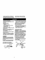
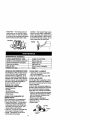
ATTACHING THE HANDLE
(some units are already assembled)
• Assemble handle to the unit as shown;
make sure bottom of handle is seated
in the groove in the trigger housing.
NOTE: Knob must be assembled on
the right hand side of the unit as
shown in the illustration,
• Make sure the bolt is seated into the
hex-shaped hole in the handle.
• Pivot handle to a comfortabTeposition.
• Tighten handle securely,
ATTACHING
SHIELD
WARNING: The shield must be properly installed.The shield providespartial
protectionfrom the riskof thrown objects
to the operatorand othersand is
equippedwith a line limiterwhich cuts
excess line to the proper length. The line
limiter (on undersideof shield) is sharp
and can cut you. For properorientation,
see illustration in Operation section.
o Remove wing nut from shield.
* Insert bracket into slot as shown.
• Pivot shield until bolt passes through
hole in bracket.
. Securely tighten wing nut onto bolt,
Blot
Shield
Bracket
\
Wing
nut
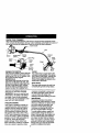
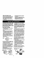
KNOWYOURTRIMMER
READ
THIS
OPERATOR'S
MANUAL
AND SAFETYRULES BEFOREOPERATINGYOUR
UNIT.Compare the illustrationswith your unff to familiarize yourself with the location of
•
controlsand adjustments.Save this manual for futurereference.
Assist Handle
Tube
/
Muffler
Engine Stop
Switch
Starter
Rope
Trimmer
Head
Trigger
3park Plug
_
Choke
Lever
Edge
Guide
Shield
Primer
B_Ib
Fuel M_
Fill Cap
ENGINE STOP SWITCH
The engine stop switch is used to stop the
engin_ Push and hold the engine stop
switch in the STOP OrOFF position until
the engine has fully stopped.
PRIMER BULB
The primer bulb removes air from the
fuel lines and fills them with fuel. This
allows you to start the engine with fewer pulls on the starter rope, Activate
the primer bulb by pressing it and allowing it to return to its original form.
BEFORE
STARTING
ENGINE
\'_
Line
1Jmiter
Blade
CHOKE
The choke helps to supply fuel to the
carburetor during starting. This allows
you to start a cold engine. Activate the
choke by moving choke lever to Full
Choke. After engine has started, move
choke lever to Off Choke,
EDGE GUIDE
The edge guide protectsthe unit from
contacting the ground during edging.
container momentarily to assure that
the fuel is thoroughly mixed. Always
read andfollow the safety rules
relating to fue! before fueling your unit.
IMPORTANT
Experience indicates that alcohol
blended fuels (called gasohol or using
ethanol or methanol) can attract moisture which leads to separation and
formation of acids during storage.
Acidic gas can damage the fuel system of an engine while in storage.
To avoid engine problems,empty fuel
system before storagefor 30 days or
longer. Drain gas tank, start engine and
let it run u_l fuel linesand carburetor
are empty.Use fresh fuel nextseason.
Never use engine or carburetor cleaner
products in the fuel tank or permanent
damage may occur.See the STORAGE
section for additionalinformation.
WARNING: Be sure to read the fuel
information in the safety rules before
you begin. If you do not understand
the safety rules, do not attempt to fuel
your unit. Call 1-800-235-5878.
FUELING ENGINE
This engine ts certified to operate on
unleaded gasoJine.Before operation,
gasoline must be mixed with a good
quality 2-cycle air-cooled engine oil.
We recommend Craftsman brand oil.
Mix gasoline and oil at a ratio of 40:1
(A 40:1 ratio is obtained by mixing 3.2
ounces of oil with 1 gallon of unleaded
gasoline)• DO NOT USE automotive oil
or boat oil. These oils will cause
engine damage. When mixing fuel,
follow instructionsprinted on container.
Once oil is added to gasoline, shake
5
HOW TO STOP YOUR UNIT
Push and hold the engine stop switch
in the STOP or OFF position until the
unit has fully stopped.
STARTING YOUR ENGINE
Engine
_op
could require puIllngthe starter handle
many times depending on how badly
the unit is flooded.
If the unit still doesn't start, refer to
TROUBLESHOOTINGchart or call
t -800-235-5878.
ChokeLever
__
OPERATING INSTRUCTIONS
OPERATING POSITION
__
ALWAYSWEA_.,_-HOW TO START YOUR UNIT
WARNING: The trimmer head wil!turn
while starting the engine. A hot muffler
can cause serious bums.
COLD ENGINE STARTING OR
STARTING AFTER REFUELING
• Set unit on a fiat surface.
Staffing Pos_on
• Slowly press primer bulb 6 times.
Move choke lever to FULL choke.
Trigger
Bulb
• Squeeze and hold trigger through all
remaining steps.
• Pull starter handleuntil engine attempts
to start, but no mere than 5 pulls.
• Move choke lever to HALF choke.
• Pull starter handle until engine runs.
° Allow engine to run 10 seconds, then
move choke lever to OFF choke.
RESTARTING A WARM ENGINE
° Move choke lever to OFF choke.
• Pull starter handle until engine starts.
• If engine does not start in 5 pulls,follow
instructions in STARTINGA COLD ENGfNE.
DIFFICULT STARTING OR
STARTING A FLOODED ENGINE
Flooded engines can be started by
placing the choke lever in the Off
Choke pos_on; then, pull the rope to
clear the engine of excess fuel. This
6
Eye Protection
Long Pants _.
Hea_ulh::m:ou_r _g_
your left.
Do not run the engine at a higher speed
than necessa,,y.The cutting linewill cut
efficientlywhen the engine is run at less
than full throttle.At lower speeds, there
is lessengine noise end vibration.The
cuttingtine will last longer and will be
less likelyto "weld" onto the spool.
Always release the throttle tdgger and
allow the engine to return to Idle speed
when not cuWng.
To stop engine:
• Release the throttle trigger.
• Push and hold the engine stop
switch in the STOP or OFF position
untilthe unit has fully stopped.
TWiST-N-EDGE
• Pull the tab toward the engine,
• Twist the tube to the edging position;
release tab.
TRIMMER LINE ADVANCE
Trimmer line will advance approximately 2 in, (5 cm) each time bottom of
trimmer head is tapped on the ground
with engine running at full throttle.
The most ef_cientline length is the
maximum lengthallowed by line limiter.
Always keep the shield in place when
the tool is being operated.
To Advance Line:
• Operate the engine at full throttle,
- Hold the
trimmer head parallel to and
above the grassy area.
• Tap the bottom of the tdmmer head
lightly on the ground one time. Approximately 2 in. (5 cm) of line will be
advanced with each tap.
Toadvance line, tap bottom of trimmer
headon groundone time.
AJways tap the trimmer head on a
grassy area. Tapping on surfaces such
as concrete or asphalt can cause excessive wear to the trimmer head.
If line is worn down to 2 in. (5 cm) or
less, more than one tap will be required
to obtain the most efficientline length.
WARNING: Use only .080" (2 ram)
diameter line. Other sizes of line will
not advance properly and can cause
serious injury. Do not use other materials such as wire, string, rope, etc, Wire
can break off during cutting and become a dangerous missile that can
cause serious injury.
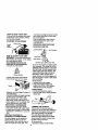
CUTTING METHODS
WARNING: Use minimum speed and
do notcrowdthe line when cutting
around hard objects (rock, gravel, fence
posts, etc.), which can damage the trimmer head, become entangled in the line,
or be thrown causing a sedous hazard,
• The tip ofthe line does the cutting.
You witl achieve the best performance
and minimum line wear by not crowding the line into cutting area, The right
and wrongways are shown below.
Tip ofthe Line
r Une CrowdedInto
DoesThe Cutting1 Work
Are_,_
Wrong"
., The line will easily remove grass and
weeds from around walls, fences,
trees and flower beds, but it also can
cut the tender bark of trees or shrubs
and scar fences. To help avoid damage especially to delicate vegetation
or trees with tender bark, shorten line
to 4-5 in. (10-13 cm} and use at less
than fulf throttle.
• For trimming er scalping, use less
than full throttle to increase line life
and decrease head wear, especially:
• During light duty cutting.
• Near objects around which the line
can wrap such as small posts,
trees or fence wire.
• For mowing or sweeping, use full
throttle for a good clean job.
WARNING: Always wear eye protection, Never lean over the trimmer head.
Rocks or debds can ricochet or be
thrown into eyes and face and cause
blindness or other serious injury.
TRIMMING - Hold the bottom of the
trimmer head about 3 in. (8 cm) above
the ground and at an angle. Allow only
the tip of the line to make contact. Do
not force trimmer line into work area.
Trimming
J,
3 in. (8 cm)
Above Ground
SCALPING - The scalping technique
removes unwanted vegetation. Held
the bottom of the trimmer head about 3
in. (8 cm) above the ground and at an
angle. Allow the tip of the line to strike
the ground around trees, posts, monuments, etc. This technique increases
line wear.
Scalpi_,
.......
MOWING - Your trimmer is ideal for
mowing in places conventional lawn
mowers cannot reach, in the mowing
position, keep the line parallel to the
ground. Avoid pressing the head into
the ground as this can scalp the
ground and damage the tool.
Mowing
SWEEPING - The fanning action of
rotating line can be used for a quick
and easy clean up. Keep line parallel
to and above the surfaces being swept
and move the tool from side to side.
EDGING - The Twist-N-Edge feature
allows for easy edging of sidewalks,
patios, driveways, etc. Adjust trimmer
to the edging position.Allow only the
tip of the llne to make contact. Do not
force trimmer line into work area.
Edging
_,_
MAINTENANCE SCHEDULE
CARE & MAINTENANCE TASK
WHEN TO PERFORM
Check for Loose fasteners and parts
Check for damaged or worn parts
Clean unit and labels
Before each use
Before each use
After each use
Clean air tilter
......
Replace spark plug
GENERAL RECOMMENDATIONS
The warranty on this unit does not cover items that have been subjected to
operator abuse or negligence. To receive full value from the warranty, the
operator must maintain unit as instructed in this manual. Various adjustments
w_ll need to be made periodically to
properly maintain your unit.
CHECK FOR LOOSE
FASTENERS AND PARTS
• Spark Plug Boot
. Air Rter
• Housing Screws
• Assist Handle Screws
• Shield Screw
CHECK FOR DAMAGED OR
WORN PARTS
Refer replacement of damaged/worn
parts to your Sears Service Center.
• Engine Stop Switch - Ensure switch
functions propedy by pressing and
holding the switch in the "Stop" position. Make sure engine stops; then
restart engine and continue.
• Fuel Tank - Do not use un_ if fuel tank
showssigns of damage or leaks.
• Shield - Discontinue use of unit if
debris shield is damaged.
Every 5 hours of operation'
Yearly
CLEAN UNIT & LABELS
• Clean the unit using a damp cloth
with a mild detergent.
* Wipe off unit with a c{ean dry Moth.
CLEAN AIR FILTER
Do not clean filter in gasoline or other
flammable solvent to avoid creating a
fire hazard or producing harmful evaporative emissions.
A dirty air filter decreases engine performance and increases fuel consumption and harmful emissions. Always
clean after every 5 hours of operation.
• Clean the cover and the area around
it to keep dirt and debris from falling
into the carburetor chamber when
the cover is removed.
• Remove parts as illustrated.
• Wash the filter in soap and water.
• Allow filter to dry.
• Replace parts.
Filter
S
Cover
REPLACE
SPARKPLUG
Replace the spark plug each year to
ensure the engine starts easier and
runs better. Set spark plug gap at
.025 in. Ignition timing is fixed and
nonadjustable.
, Twist, then pull off spark plug boot.
ADVANCING THE CUTTING UNE
Advance line by tapping bottom of cutting head lightly on the ground while
engine is running at full speed, A metal
blade attached to the shield will cut the
line to the proper length.
REPLACING THE LINE
• Remove the spool by firmly pulling
on the tap button.
° Clean entire surface of hub and
spool.
• Replace with a pre-wound spool, or
cut a length of 20 feet of .080" (2
mm) diameter Craftsman ® Pro Trimmer line. Never use wire, rope,
string, etc,, which can break off and
become a dangerous missile.
• Insert about 1/2 inch (1 cm) of one
end of the line into the small hole inside the spool.
Small
Spool
Hole __\\.,__....
• Wind the line evenly and tightly onto
the spool. Wind in the direction of the
arrow found on the spool.
• Push the line into the notch, leaving
3 to 5 inches (7 - 12 cm) unwound.
° Insert the line into the exit hole in the
hub as shown in the illustration.
• Align the notch with the line exit hole.
• Push the spool into the hub until it
snaps into place.
° Pull the line extending outside the
hub to release it from the notch.
Linein
• Remove spark plug from cylinder
and discard.
• Replace with Champion RCJ-SY
spark plug and tighten with a 3/4 in.
socket wrench (!0-12 ff.-lbs).
• Reinstall the spark plug boot.
CARBURETOR ADJUSTMENT
WARNING: The trimmer head will be
spinning during most of this procedure.
Wear your protective equipment and
observe all safety precautions. After
making mixture adjustments, recheck
idle speed.
Carburetor adjustment is critical and if
done improperlycan permanently
damage the engine as well as the carburetor. If you require further assistance or are unsure about performing
this procedure, call t-800-235-5878.
Old fuel, a dirty air filter, a dirty fuel filter, or flooding may give the impression of an improperly adjusted carburetor. Check these conditions before
adjusting the carburetor.
The carburetor has been carefully set
at the factory. Adjustments may be
necessary if you notice any of the following conditions:
° Engine witl not idle. See "Idle Speed"
under adjusting procedure.
• Engine dies or hesitates instead of
accelerating. See "Acceleration
Check" under adjusting procedure.
• Loss of cuffing power, See "Mixture
Adjustment" under adjusting
procedure.
There are two adjustment screws on
the carburetor.They are located in the
area just above the pdmer bulb.
Mixture Screw (with
Umiter Cap)
Idle
Speed
Screw
Air Filter
Cover
Line exit hole
CARBURETOR
PRESETS
When making carburetor preset adjustmerits, do not force plastic limiter caps
beyond stops or damage will occur.
If carburetor presets are not needed,
proceed to "Adjusting Procedure, Idle
Speed."
To adjust presets:
• Turn mixture screw counterclockwise
until it stops.
• Turn the idle speed screw clockwise
until it stops. Now turn counterclockwise 4-t/2 turns.
• Start engine, cut grass for 3 minutes,
and proceed to the adjustment
section. If engine does notstart,
refer to troubleshooting chart or call
the 1-800 number listed on the front
of this manual.
• If engine performance is acceptable
at the preset positions, no further
adjustment is necessary.
ADJUSTING
PROCEDURE
Idle Speed
Allow engine to idle. Adjust speed until
engine runs without stalling.
• Turn clockwise to increase engine
speed if engine stal/s or dies.
• Turn counterclockwise to decrease
speed.
Prepare unit for storage at end of season or if it will not be used for 30 days
or more.
WARNING:
• Allow engine to cool, and secure the
unit before storing or transporting.
• Store unit and fuel in a well ventilated area where fuel vapors cannot
reach sparks or open flames from
water heaters, electric motors or
switches, furnaces, etc.
• Store unit with all guards in place.
Position unit so that any sharp object
cannot accidentally cause injury.
° Store unit and fuel well out of the
reach of children.
EXTERNAL SURFACES
ff your unit is to be stored for a period
of time, clean it thoroughly before storage. Store in a clean dry area.
• Lightlyoil external metal surfaces.
No further adjustments are necessary
if performance is satisfactory.
Mixture Adjustment "H"
DO NOT operate engine at full throttle
for prolonged periods while making adjustments. Damage to the engine can
occur. Extend line to the length allowed by the line limiter and cut some
grass. Based on performance while
cutting, turn the mixture adjustment in
1/16-turn increments as follows:
• Clockwise until the engine has good
power while cutting with no hesitation.
Do not adjust by sound or speed, but
judge by how well the engine performs while cuing.
• Counterclockwise if the engine has
speed but dies or lacks power while
cutting.
After completing adjustments, check
for acceleration. Reset if necessary.
Acceleration Check
If engine dies or hesitates instead of
accelerating, turn mixture adjustment
counterclockwise until you have
smooth acceleration. Recheck and adjust as necessary for acceptable performance.
FUEL SYSTEM
Under Fueling Engine in the Operating
Section of this manual, see message
labeled IMPORTANT regarding the use
of gasohol in your engine.
Fuel stabilizer is an acceptable alternatk,e in minimizing the formation of
fuel gum deposits during storage. Add
stabilizer to the gasoline in the fuel
tank or fuel storage container. Follow
the mix instructions found on stabilizer
container. Run engine at least 5 minutes after adding stabilizer.
CRAFTSMAN40:1,2-cycle engine oil
(air cooled) is already blended with
fuel stabilizer. If you do not use this
Sears oil, you can add a fuel stabilizer
to your fuel tank.
10
ENGINE
• Remove spark plug and pour I teaspoon of 40:1, 2-cycle engine oil (air
cooled) through the spark plug opera
ing. Slowly pull the starter rope 8 to
10 times to distribute oil,
• Replace spark plug with new one of
recommended type and heat range.
• Clean air filter.
• Check entire unit for loose screws,
TROUBLESHOOTING
TROUBLE
Engine will not
start.
idle properly:
Engine will not
accelerate,
lacks power,
or dies under
a load.
OTHER
• Do not store gasoline from one season to another.
• Replace gasoline can if it startsto rust,
CHART
CAUSE
• Engine flooded,
• Fuel tank empty.
Spark plug not firing.
Fuel not reaching
carburetor.
• Compression low.
:E.gine
willnit
nuts, and bolts. Replace any damaged, broken, or worn parts.
• At the beginning of the next season,
use only fresh fuel having the proper
gasoline to oil ratio.
REMEDY
; See
"Starting
Instructions."
Fill tank
with correct
fuel mixture.
Install new spark plug.
; Check for dirty fuel filter; replace,
Check for kinked or split fuel line;
repair or replace.
• Contact Sears Service.
• Adjust idle speed screw
clockwise to increase speed.
ldte speed set too low.
Idle speed set too high. • Adjust idle speed screw counterclockwise to reduce speed.
• Carburetor requires
• See "Carburetor Adjustments."
adjustment.
• Crankshaft seals worn. • Contact Sears Service.
• Contact Sears Service.
,• Compressionl0w.
• Air filter dirty,
• Clean or replace air fitter.
• Spark plug fouled.
• Clean or replace spark plug
and re-gap.
• Carburetor requires
• See "Carburetor Adjustments,"
adjustment.
• Contact Sears Service.
• Carbon build up.
• Contact Sears Service.
• Compression low.
Engine smokes o Choke partially on,
J• Adjust choke.
• Fuel mixture incorrect. • Empty fuel tank and refill with
' excessively.
correct fuel mixture.
,• Air filter dirty.
Clean or replace air filter.
° Carburetor requires
• See "Carburetor Adjustments."
adjustmenL
Engine runs he1 • Fuel mixture incorrect.
• Spark plug incorrect.
• Replace with correct spark plug.
• Carburetor requires
See "Carburetor Adjustments."
adjustment
• Contact Sears Service.
• Carbon build up.
• See"Fueiing
Your
Unit."
tl
YOUR WARRANTY RIGHTS AND
sponsible for presenting your lawn and
OBLIGATIONS: The U. S. Envirengarden equipment engine to a SEARS
mental Protection Agency/California
authorized repair center as soon as a
Air Resources Board and SEARS,
problem exists. Warranty repairs
ROEBUCK AND CO., USA are
should be completed in a reasonable
pleased to explain the emissions conamount of time, not to exceed 30 days.
trol system warranty on your lawn and
If you have any questions regarding.
garden equipment engine. All new utilyour warranty rightsand responsibdiity and lawn and garden equipment
ties, you should contact your nearest
authorized service center or call
engines must be designed, built, and
SEARS at 1-800-473-7247 WARRANequipped to meet the stringent antismog standards. SEARS must warrant
TY COMMENCEMENT DATE: The
the emission control system on your
warranty period begins on the date lhe
lawn and garden equipment engine for
lawn and garden equipment engine is
the periods of time listed below pro,
purchased. LENGTH OF COVERvialed there has been no abuse, neAGE: This warranty shall be for a periglect, or improper maintenance of your
od of two years from the initial date of
lawn and garden equipment engine.
purchase, WHAT IS COVERED: REPAIR OR REPLACEMENT OF
Your emission control system includes
parts such as the carburetor and the
PARTS. Repair or replacement of any
ignition system. Where a warrantable
warranted part wilt be performed at no
condition exits, SEARS will repair your
charge to the owner at an approved
lawn and garden equipment engine at
SEARS servicing center, if you have
no cost to you. Expenses covered unany questions regarding your warranty
der warranty tnclude diagnosis, parts
rights and responsibilities, you should
and labor. MANUFACTURER'S WARcontact your nearest authorized serRANTY COVERAGE: If any emissions vice center or call SEARS at
1-800-473-7247. WARRANTY PErelated part on your engine (as listed
under Emissions Control Warranty
RIOD: Any warranted part which is not
scheduled for replacement as required
Parts List} is defective or a defect in
the materials or workmanship of the
maintenance, or which is scheduled
engine causes the failure of such an
only for regular inspection to the effect
emission related part, the part wilt be
of "repair or replace as necessary"
repaired or replaced by SEARS.
shall be warranted for 2 years. Any
OWNER'S WARRANTY RESPONSIwarranted part which is scheduled for
BILITIES: As the lawn and garden
replacement as required maintenance
equipment engine owner, you are reshall be warranted for the period of
sponsiblefor the performance of the
time up to the first scheduled replacerequired maintenance listed in your
ment point for that part. DIAGNOSIS:
Owner's Manual. SEARS recommends
The owner shall not be charged for
that you retain all receipts covering
diagnostic labor which leads to the demaintenance on your lawn and garden
termination that a warranted part is deequipment engine, but SEARS cannot
factive if the diagnostic work Js perdeny warranty solely for the lack of reformed at an approved SEARS
ceipts or for your failure to ensure the
servicing center. CONSEQUENTIAL
performance of all scheduled mainteDAMAGES: SEARS may be liable for
nance. As the lawn and garden
damages to other engine components
equipment engine owner, you should
caused by the failure of a warranted
be aware that SEARS may deny you
part still under warranty. WHAT IS
NOT COVERED: All failures caused
warranty coverage if your lawn and
garden equipment engine or a part of it
by abuse, neglect, or improper maintenance are not covered. ADD-ON OR
has failed due to abuse, neglect, imMODIFIED PARTS: The use of add-on
proper maintenance, unapproved
modifications, or the use of parts not
or modified parts can be grounds for dismade or approved by the original
allowinga warranty claim. SEARS is not
equipment manufacturer. You are reliable to cover failures of warranted
12
parts caused by the use of add-on or
modifiedparts. HOW TO FILE A
CLAIM: tf you have any questions regarding your warranty rights and responsibilities, you should contact your
nearest authorized service center or
call SEARS at 1-800-473-7247.
WHERE TO GET WARRANTY SERVICE: WaJTantyservices or repairs shall
be providedat all SEARS service centers. call: 1-800-473-7247. MAINTENANCE, REPLACEMENT AND REPAIR OF EMISSION RELATED
PARTS: Any SEARS approved re-
13
placement part used in the performance of any warranty maintenance
or repair on emission related parts will
be provided without charge to the owner if the part is under warranty. EMISSION CONTROL WARRANTY
PARTS LIST: Carburetor, Ignition System: Spark Plug (covered up to maintenance schedule), Ignition Module.
MAINTENANCE STATEMENT: The
owner is responsible for the performance of all required maintenance as
defined in the owner's manual.
Jii
H
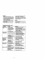
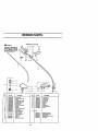
REPAIR PARTS
H
_
SEARS
WARNING
2
MODEL 358.795190
5
21 25
22
6
;l
All repak_ adju_sqLrnentsand
maintenance
not _mcdbed
Tn _e operator's
Manual
must be performed by qualified _'tce
personnel.
15_
18
Ref.
1.
2.
3.
4.
5.
6.
7,
8.
9.
10.
11.
12.
1,3,
14.
part N_
530053613
530016179
5_)0049107
530047_23
530047924
530047919
530015820
530042084
5300_40_0
5_eO'_g
_522._
530015814
,5,._006_930
75.
16.
17.
18.
530095380
S-3040195_
530401 g57
Ref.
Description
Drive Sh_
Screw-Thrott{e Hsg.
TAgger
ThfotUe Hsg, (Right)
l_rot_e Hog, (Left)
Assist Handle
IBoR-Shie]d
Part No.
19.
20,
21.
_'_,
23.
24.
25_
26.
27.
28.
Spring*COmpress{on
Actual"
Wssher
Drive Sh_ Hsg. Ass_
Une Umi[er
Screw-Uric Um_ter
71-85816
530047912
5300479_1
530016173
530016152
530094543
530015810
530049844
530049845
5,30015966
Descflptlon
Spool w/line
Lo_ator-nght
Locator-le_
Bo_-Hand_e
_,_ngnt_
Ou=Cup
Screw
Ed_e Guard
Cfamp.-Mcunt_ng
Nc_ Shown
({nd, 12 & 13)
Cu_ing Head Ass'y,
(_. ie-19)
Hub ASS'y
I
Clip-Reindeer-Head
14
580087757
530047467
5_54054
530052301
530O475O0
Oper_or's Manual
Shait Warning DecaJ
Shield Decal
SteJling Irt_._nJctionDecal
Stop Oec_
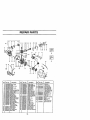
'REPAIR PARTS
/
31
_37
I0
1718
32
52
33
64
67
1
58
13
23
62
6
I
60
ReL Part No_
Description
"53004_86
-Starter Sp._ng
Screw
Ret_n_r-PulJey
Screw
St.ader Handle
.SCrew
530015880
530015810
530019243 Gasket-Cylinder/Carb.
Champion Spark Plug (RCJ-SY)
580035421 G_sket-Carb.
5300_5945 R_ainer RJng-C'P.ase
530049390 L_d Wire
530049389 : _mund W_re
F_ywhee!A._'y.
530052266 !gnit_on Module
530035145
530015954
530016828
_pacer-lgnit. Module
Screw-lgni_. JVl_du_o
!washer-Flat
530027953
630_14532
530069615
53004,_03
5300148Sl
Dr_veCoupling
C_sJ_kshaft Ass'y.
Connectin._ Rod kssy.
Rston Ring
Cra._kcase,Assy,
0not _0 & 23-2s)
5300.32125
Inner Be_r_g
530032124
Outer Be_dng
5300_9179
C'case Seal
530015941
Ret. Rin_/C'sha.ft
530036578 ; r_;ufflerBody'
I
Ref.
Part NO.
De.scdptlon
28. 530036577
Muffle_ Cover
29. ' 5.30053500
Iv_ff]er _fis-Ex_c
30.
530053499
Muffler Baffle-First
31L 5..'.'.'.'.'.'.'.'._016197
Muffler S_ng
32.
530049377
Rear Shroud
Gasket-C'case
CyJinder I_
•
37.
38.
39.
40_
41.
42.
43.
44.
i
J ,_. •
47.
48.
530015849
530019223
53006O99O
54.
Part
NO.
_70
55.
! 58.
57.
5300"_4347
5300143_62
530069618
58.
5300'_4729
I Carb._,d_or _
, Sc_ew_Ce_b Adp_r.
Gasket-Cyfinder
Carburetor Assy W_t
(_ncl.
Lim_erCap)
5300'E516u?. Piston Pin RezaJner
53O047914
C_oke plate
530015557
SC_=W
5300479_6
C;_oke Lever
530015254
Wa.she/
530015852
C;noke Spacer
5.300490_9
530047932
530049079
530015957
Re£
_
A_t
J_JrBOX
F'd_erFoam
_'r F_Jte_Covet
Screw-_'_
_
•
51.
52.
53004_066
530049299
530015953
5"_.g6793
"fhro_e Cable A..%_
Fue_Tank ASS_V.
' Screw-CyTinder
Shroud Iso(ator
53.
530069247
Fua_ Une-CarbjS"ank
15
Desc_pt_on
M_fflfer KJ!
(Incl. 27-31)
Fuel Cap Assy.
Fuel P_d.J.tpAssy
E_g_o Ga.sket F._
0nd. 7,9_33, 37)
O'caselC'_af_
Assy.
(Ind,10,19,22-26)
59. 550038114
60.
530049469
61. 5.30069232
62, 580069400
63.
64.
65.
66.
530069216
5.30016080
5300367_
530069987
On/Off Swath
F_n Housing ASSy.
Rope I_t
St_r
Pulley _t
(inc. 64)
Fuel LJne-Carb/T_k
SC/eW
Isotator-C'ca_se
piston Wd
67.
530069380
(_nd. 2!,68 & Pin)
_Vr_'i_
W,'t
illll
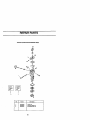
REPAIR PARTS
ill lliHlll
Carburetor
As_emb!y
Kit Number
#53{)069990
-W/t_230
f
3
2
Ref.
Part NO.
Description
j
1.
2,
530038404
53006_842
530069844
Urn;tar Cap
Carburetor Reip_r
Gasket/Diaphragm
16
I_