1
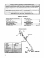
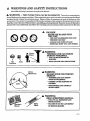
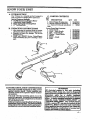
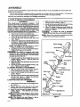
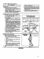
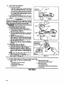
IMPORTANT
Operator'g
Manual
MANUAL
Do Not Throw Away
_
Model No.
257.798051
Always Wear Eye Protection.
8E_/_8/C RRFT$iviRNo
ELECTRIC
Read the Operator's Manual and
FoIlow All Warnings and Safety
Instructions.
Failure To Do So
Can Result in Serious Ix_t_y.
DOYLE
TRIMMER
INSUI_TED
• Assembly
• Maintenance
• Operation
• RepairParts
!y'
Sold by Sears, Roebuck
and Co., Chicago,
IL60684
USA _
,.=,l,
530400888-2-03/28/93
,,i,
, .,i,.,
,ill
i,
© 1993, Sears,Roebuck and Co .
ONE YEAR LIMITED WAP_LA_NTY ON UB.AFTSMAN WI_EDWACKER®
_or One Year from date of purchase, when
maintenance
ins_actions
in the operator's
This warranty
excludes
If th_
Line Trimmer
Electric
nylon
this Elect_e Line Trimmer
n_auuat, Sears will repair
line or any other
part_ which
is used for commor_al
is machined
and used accordLng to _he operating
and
free of charge any defect in material or workmanship.
are expendable
or rentalpurposes,
_
parts
wsrranty
WARRANTY SERVICE IS AVAILABLE BY RETURNING THE UNIT TO THE _
THE UNITED STATE_
and become
worn
during
norm_t use.
does not apply.
SEARS SERVICE CENTEPJDEPARTM_NT
iN
This warrant y applies o_ly while this product is in use in the United S'_ates_
Thiswarr_utyg_vesyou sl_Cific
legalrights,
and you m_y alsohsve other_ghts which varyfrom state_ostats.
SEAR_
ROEBUCK
AND CO.
DEP_D/817WA
TABLE
HOFFMANESTATES,
IL 60179
OF CONTENTS
WARNINGS AND SAFETY INSTRUCTIONS
... 3
KNOW YOUR UNIT ..................
-.......5
ASSEMBLY ..................................
6
A. Shield &Tube Attachment ...............
6
B. Assist Handle Attachment ................
6
C. Motorfl_igger Housing Assembly .........
6
D. Pre-OperationChecks...................
7
E. ExtenslonCord Attachment ..............
7
E OperatingPosition.......................
7
USING YOUR UNIT
A. LineTrimmer Safety.....................
8
B. Trimmer LineAdvance ...................
8
C.Cutting
Methods ........................
9
D. LineReplacement .......................
10
GENERAL MAINTENANCE
A. Maintenance Safety ......................
11
B. Trouble Shooting Chart ..................
11
ACCESSORIES .............................
11
PARTS AND SERVICE ...............
Bvzk Cover
SPECIFICATIONS
Assist Handle
,/
Cord
Retainer
MODEL:
257.798051
MOTOR:
7/8PIP
VOLTAGE:
120 Volts AC
,
J
AMPS:
6.0
CUTTING PATH:
17_
CUTTING LINE:
LINE FEED: •
WEIGHT;
Sh_d
.080" Dia. Laser Line®
• Automatic
•
.... t . 9pounds
TrimmerHea_
• •
--2-
•
•
•
,
•
r
WAF ' , GS
AriD SAFETY INSTRUCTIONS
(See Additional
Safety Instructions
throughoutthisManual)
WARNING
- THIS
POWER
TOOL
CAN
BE
US! This unit a__ cause serious in_
DANGERO
jury or blindnessto the operator and others. When using electric power tools, basic safety precau_ior_ faust be foHowexl
toreducetherisko£injury,
fire,
and electric
shock.Failure
tofollowallinstructions
can resultinblindness
orother
seriousinju_.The operator
isresponsible
forfollowing
thewarningsand instructions
in thismanual and on theunit.
Read the entire Operator's Manual before assembling
and usingthis unit! Restrict the use of this unit to
persons who read, understand,
and follow the warnings and instructions
in this manual and on the unit.
A
DANGER
Q@@
...............
_,l,l,,llll l
i
NEVER
USE BLADES
WITH
THIS UNIT.
-
THIS UNIT IS DESIGNED
TRIMMER USE ONLY
FOR LINE
-
ABLADE CAN COME OFFAND
SERIOUSLY'HURT
YOU AND OTHERS.
illll
2y
Thrown
_
AWARNING
TRIMMER
*
Eye
Protection
ts
60 Foot
Hazard Zone
LINE CAN THROW
-
YOU CAN BE BLINDED
INJLrREDo
OR
-
WEAR EYE AND LEG PROTECTION.
_ikW_G
HAZARD
ZONE FOR
THROWN
OBJECTS
- _LmZ
CANTHROW
OBJECTSviO_
v:
i lliHl
ii
,
iil
ill ii,l,i
,
,,,
OTHERS CAN BE BLINDED OR
INJURED,
KEEP PEOPLE AND ANIMALS
30 FEET AWA_£
illllllllll
i,ii
•
p
,=
illll
i i i
,,,,,,,,,,i,i,
Ak WARNING
READ OPERATOR'S
MANUAL.
- FOLLOWALL WARNINGS AND
INSTRUCTIONS.
Operator's
Manuali
i
•
ii
iil_ll,
i i"
;
i,iiiii
Safety
Labels
iii iii
"•
-
F_
TO DO SO CAN RESULT
IN SERIOUS INJUR_
,,i,,,
ii illlllli
illl ii
i ii
i
i
i
WARN GS
AND SAFETY INSTRUCTIONS
A OPERATOR
SAFET_Y
DRESS PROPERLY--Always
wear eye protection. Always wear heavy, long pants, beets, and
gloves. Do not go barefoot or wear sandals, short
pants, jewelry,, ':loose d0thimg; or clothing with
loosely hanging straps, ties, tassels, etc.; they can
be caught inmovingpar_.
Secure hair so it is above
shoulder length_ Being fully covered will help protect you hum pieces of toxic plants such a_ poison
ivy_rownby_z_mmerlinewhichcouldbemoreefa
hazard than _ouching the plant itself.
2. STAY ALERT--Watch_vhat
you are doing. Do
not operate this unit when you are tired, il!, or under the influence of alcohol, drugs, or medication.
3. AVOID UNINTENTIONAL STARTING OF THE
UNIT--Never
carry the unit with your finger on
the switch. Be sure the switch is in the off position
before connecting the extension cord.
4. Restrict the use of this unit to persons who read,
understand,
and follow thewarningsand instructionsin this manual and on the unit.
_ UNIT SAFETY
1. Inspect entire unit before each use. Replace damaged parts. Make sure all fasteners arein place and
securely fastened.
2. Replace trimmer bead parts that are cracked,
chipped, or damaged before using the unit.
3. Use only .080" diameter SEARS Laser Line. Never
use wire, rope, string etc.
4. Instal! the shield properly before using the unit.
5. Use onty the specified trimmer head. Make sure
the trimmer head is properlyin_a]lad end securety
fastened. Refer to '_ssembly/'
6. Use only genuine SEARS accessories as recommended for this unit.
1.
A ELECTRICAL
A CUTTING
lf sltua_ns
occur w_h
Contwmt your _
A MA/NTENANCE
SAFETY
1. Maintain the unit according to recommended prosedures.
Keep cuttingline
atthe proper tangt_
2. Have all internal service performed by SEARS qualified service personnel to avoid creal_g a hazard
and/orvoidingyourwarranty
3. DISCONNECT
UNIT FROM POWER
SOURCE
when notinuseorbeforeperformlngmaintenance_
4. Never douseor squirt
theunitwithwater or any
other liquid.
Clean with a damp spo_ee.
See
"Maintenance-- Storage/'
5. Keep the air vents clean andfreeofdebris to avoid
overheating the motes Clean after each use_ See
"Specifications" for locations.
6. Use only genuine SEARS raplaeemen_ par_ as recommende_
A
TRANSPORTING
AND
STORAGE
1. Hand carry the unit with the motor stopped.
2. Allow the unit to coot and secure the unit before
storing or transporting in a vehicle:
• 3. Store the unit so the line l_miter cannot accidentally cause injur_.
4. STORE UNIT INDOORS, unplugged, in a high,
dry place out of the reachofchildren.
are nat eo __ed in.this manual, use care and #oad __.
_rvwe
_.enter/Dep_rtmer_
if yo= _
assi$_
SAVE THESE INSTRUCTIONS
--4--
SAFETY
I. Inspec£ the areato be cut before each use. Remove
objects (rocks, broken glass, nails, wire, string, etc.)
which can be thrown or become entangled in the
trimmer head.
2. KEEP CHILDREN AWAY--Keep others including children, animals, bystanders and helpers outside the 60 foot Hazard Zone. Do not permit children to contac_ extension corder trlmmen Stop the
malt fmmedmtely if you are approached.
3. Avoid aeeidental start2ng. Be sure the switch is in
the "OFF _ position and keep your hand and fingers
away from the switch while connecting the unit to
an extension cord or when carrying a umt connected to a power source.
4. Stop the unit end disconnect the power source
when not in use.
5. DO NOT OVERREACH OR STAND ON UNSTABLE SUPPORT--Keep
firm footing and balance.
6. Keep the trimmer head below waist level.
7. Do not raise unit above your waist. The trimmer
head can come dangerously dose toyourbody.
8. Keep all parts of your body away from trimmer
head when unitisnuming.
9- USE UNIT PROPERLY'_-U_e only for jobsexplalnedinthismanual Do notforce theunit.
SAFETY
1. Use only a 120 A.C. voltage supply as shown on the
name plate of the unit
2. Avoid dangerous sit_ations. Donotuseinthepresonceofflammableliquids
orgasestoavoid creating
a fireorexplosion
and/orcausingdamage tounit
3. WARNING--T0
REDUCE THE RISK OF
ELECTRICAL SHOCK--Do
not use in damp or
wet locatmns or around swimming poah, hOt tubs,
etc. Do not expose to anew, rain, or water to avoid
thepossibility
of electrica! shock.
4. WARNING--Use
extension
cords specificelly
marked as suitable foroutdoorappliances having
electrical
ratingnot
lessthantheratingoftheunit.
An underrated extension cord will cause a drop in
• llne votf_ge resul_ingin loss ofpower and overheating. if.in doubt, use the next heavier gauge. The
Smaller the gauge number, the heavier the cord.
(NOTE: Figure2 shows thecorrect
sizetobeused
dependingon thecordlength).
Do notusea damagedextension
cord.
5. DO NOT ATTEMPT
TO REPAIR UN_T--Inspect the insulation and conne_ore on the unit and
extension cord before each use. If there is any damage, do not use until damage is repaired by SEARS
qualified
service
peroonneL
6. Never carry the unit by the e_ension cord or yank
the extension cord to dieconne_ the uni t.
.7. To reduce the possibility of the extension cord disconnscting from the unit during opera_ion, slip the
extension cord behind the Tab on the Cord Retainer as shown in Figure 3. Plug the extension cord
into the recessed plug on the handle of the unit
Figure 3.
•
8. Do not use the unit ffswitch does not turn the unit
on and off properly. Repairs to the switch must be
made by SEA-_ qualifi_d service personnel.
9. Keep theextension
cord_learofoperatorand obstacles
at alltimes. Do not exp0se cards _ heat, oil,
water, or sharp edges.
10.Avoid any body contact with any grounded conducto_ such a metal pipes or wirefences, to avoid the
possibility of electric shock.
....(Continued)
.
I
Jill
_1
.............
............
IIH ilrll,r,iI
KNOW YOUR
I
I
I
ii
I I
I
I
,.m,,,
i
I
[
i
m l II
UN!T
Iiiiii
A. INTRODUCTION
Your Trimmer is a versatile pr_luct designed to
help you achieve a finished lawn appearance.
SpeciaI Features Include:
7/8 _
•
•
Permanent
Magnet
A stable
Semi-Automatic
17" Cutting Path
B. UNPACKING
Motor
CuttmgHead
INSTRUCTIONS
!. A_er removing the contents from the certon_
check parts against the Carton Contents list.
2. Exaudne the parts for damage_ Do not use
_ed
p_.ts.
3. Notify your SEARS
Service Ce_terfDepartmeat immediately ifa part ix missing or damaged.
IIIIII
II
ii iii
i
i
ii
C. CARTON
KEY
NO.
i
D. DOUBLE INSULATION
CONTENTS
DESCRIPTION
QTY
P/N
I. Motor/Trigger HousingAssy.
i
534903901
2. Sp_dle_
t
53490410_
1
1
1
1
i
4
1
534914801
534903000
534352400
534828701
534905501
534790301
534904001
Sh_As_.
---- upemtor
O888
s Manual (not shown)
Loose Par_s Bag Contentm
3, Assist Handle
4. Knob - Assist Handle
5. Bolt - Assist Handle
6, Washer - Assist Handle
7, shield
8. Screw - Shield
9, Tube
1
53040
iiiiiiiiiiii iiiiiiiiiiii
• ,i,
CONSTRUCTION
•_
unit is Double/nsulated
to help protect
against electric shock.
Double insulation construction consi_ of two separate _.ayers _ of e]ec_cal insu]_om
Took built with this insulation system are not in-
tended to _ grounded. As are_flt, _e extension cord
used withyour unit can be pluggedinto
120 volt electrkel outlet.
any standard
Safetypreeaufio_y,
must be observed when OIP
crating any e 'rle_'i'ca!. _tooL The double insulation
_sys_.. o_yp .r_des added pro t_tion against "__ury
H_ll
t_
& WARNING
All
electrical
:repah-s
to this" unit,
including
_a_dUsing,switeh, motor, ere., must be diagnosed
repai.t.edby qual_edservtce
personneL
Replacement
parts
for
a double
inmflated
appliance must be identical to theparts
theyr_
P! _a_e- A double insulated
appliance
is _ed
with' the words "DOUBLE
INSULATION"
or
"DOUBLE/NSULA_;"
The _nd_ol (square
wltt_
a W)
[_1 may also be max-ked on tlle
appliance.
double
fecttve
Failure to have the unit repaired by
iusulattou
ami result
const_etion
to become
in sm4ous injur_, i
inef.
_5_
/
±J
ASSEMBLY
If unit is received assembled, repeat all steps in this section to be sure assembly is correct and is adjusted for the operator.
This Operator's Manualis designed to help you assemble the tool and to provide its safe operation. It is important
that you read the entire manual to :become familiar with the toolbefore you begin assembly.
The only tool needed for assembly is a Phillips screwdriver.
...............
,,,,,
A.TUBE
,i i
ill
& SHIELD
i
A WARNING
The shield must be properly
instaHe&
The
shield reduces the risk of _
from thrown objects. Failure to install the shi.'eId in the position
shown in Figt_rc 1 canresult
mi_ury
to the operator or others.
Carefully follow assem]_y
instructions
when attaching
shield to unit. The
operator should always wear e_e protection.
1.
2.
3.
4.
5.
Remove the scTewa from the plestic bag.
Remove the top screw andnutin the sphidle housing and loosen the second screw. Figure 1.
Insert the flex sha_ through either end of the
tube. Figure 1.
Position the crease in the end of the tube as shown
in Figure 1. Slide the tube into the spindle housing until the erease is aligned with the top screw
hole in the spindle housing.
The dimple in the tube (Figure 1 ) will no
longer he visible if t_be is fully inserted.
Instal! the top screw and nut (removed in step 2.).
Tighten both upper screws securel_
The shietd is equipped with a line
limiter (on the underside
of the Shield) which
_uts line to the proper length, The llne llmiter
is sharp and can cut you.
6. Place the shield over the flex sha_ then over the
spindle housing. Figure 1. Slide the shield into
position Figure I.
7. Align the hdes on the shield with the holes in the
spindle heusing.
8. Thread the screws into the spindle housing. Fig.
ure 1. Tighten screws securbly.
B.ASSIST
1.
2.
3.
HANDLE
2.
Loosen knob and front screw on the trigger housing. Figure 1.
Remove the front screw and nut in the motor
housing and loosen the second screw, Figure I.
3. Insert the tube throughthe trigger
housinga_
ser_bly; _
The _e_
•
................
4.
Align the crease in the tube with the front screw
hole in the motor housing. Figure 1,
5, Install the front screw and nut in the motor housu
ing. Tighten both front screws securely.
6, Adjust the trigger housing and assist handle for
balance and comfort, Securely tighten the knobs
and screws.Figure I.
i cAUT!ON:I
To reduce the risk of eleetrieal
shock, do not twist the cord around the tube.
Remove the protective c_vering from the line
limiter before operating
your trimmer.
TriggerHousing
Front Screw
Tube Crease _I
Front Screw
Assist
_dle
Flex
S_aft
_andle Screw
Tube Crease
Nut
x_
Spindle
_
_
1.
Then slide tKe tube into the
headmighth_vetobe rot,_l
slightly to allow the tube to sIide completely into
the motor housing.
'
•
Knob
"_'_"_" Nut
DimpIe
HOUSING
ASSEMBLY
•
I.
iv
ATTACHMENT
Slide the assist handle onto the tube (approximately helfway down the tube). Figure I.
Insert the heir through the bolt hole in the assist
handle. Figare 1.
Placethewasheronthebolt,
thenthreadthekneb
onto the bolt, Figur e 1. Tighte_ the knob just
enough to hold the parts together.
C. MOTO_GGER
tmmt
ATTACHMENT
Second Screw
D. PRE-OPERATION
I
CHECKS
A
.
J
.Reflew all Warnings and Safety Instructions
this manual.
in[
wire, rope, string, etc.
d, Use only with the Shield properly attache&
e. Use only the specified
trimmer head parts.
M akp sure all trimmer head parts are properly installed and securely fastened.
Refer to
"Using Your Unit;"
£ Use only genuine SEARS accessories
or attaclnnents recommended
for this tool.
]
1. Before operating your tool, always:
Inspect the entire tool before each use. Replacedamaged parts.Make sureallfasteners
are
in place and securely fastened.
b. Replace
trimmer
head
parts
that
are
cracked,
chipped, broken, or damaged
in
any other way before using the tool.
i
i
E.EXTENSION
1.
2.
_
tJl
ii
i
i
,IIII_,IL
.
I
I
CORD ATTACHMENT
Use only a 120 A.C. voltage
on tte nmneplate of the unit.
supply as shown
WIRE GAUGE
RECO_ATIONS
The extension cord used to reach the power
source must be:
a. Specifically
marked as suitable
for outdooruse.
The _rd wa_t be marJ_ed with the sv_f-
b. Heavy enough to carry the current from
the power source the full length of the extension cord to the unit. Otherwise, 10ss of
power _andoverheating can occur causing damage to the unit. Refer to Figure 2 for minimum
r_threcommendations.
The cord m_t be
theproper wi_. _e.
(Approprlate extensivn
cordssreavailable.)
c. In good condition, Cord insulation
must be
intact
withno cracksordeterioration.
Plugconnectorsmust be undmusged_
3. Secure extension cord to unit as follow_
a. Loop the cord through the cord retainer as
shownlnF_tre3. Remove slack.
ii
VOLTS
25 FT.
_0 FT.
i00F_
150 FE
120
18
16
14
12
A.W.G,*
A.W.G.*
A.W.G.* A.W.G.*
"__
Figure 2
Cord
Retalne_
Plug
b. Insert the cord socket into the recessed plug on
the trimmer. FigUre 3.
j
j
ii iii
• IIIII
E OPERATING
1.
Before
ii
i1"
I
i ii
iiii i
POSITION
operating
I
........
the unit,
i iiiiiiii
OP_NG
iiiiii I iiiiiiiii
......
POSITION
stand as shown in
Eye Protection
lr_ure 4 ard checkfor the tonowin_
s. Leftarm fullyextended_hand holdingAssist
b. Rightarm sllghtly
bent, hand holding handle.
c, Unit helow waist level.
d_ Weight of unit evenly distr_uted
arms.
between
e. Without o_rator bending over,the Trhnmer
Head is near and parallel to the ground and
easily conta,L_ the matexiaI to he cut.
2.
Adjust the Assist Handle
tion°
]1 ii
to acomf0rtable
posii
_1
i
i ,iml
Plgure4
i
iii
II
I Ill I
Hill IIIIII
III IIIIIIII
NOTES
-7-
.
USE G
u
i
illllll
,,,
I
I
ii
I llll[i I
IH,,I I
I
'
I
i.i Iii ,,i
I I
YOUR UNIT
i
roll
i
•
iiiii
i
ii
i
i
i ill
ii
,,,,,,,,,,,,,,,,, iil, ll010
WARNING-THROWS
i
,,
i
OBJECTS
The rapidly moving line causes objects to be
th_own'_olently.
The shield wilt not provide
complete protec_on to the operator or otherB.
The operator
must wear a safety face
shield or goggles.
Always wear heav_
longpantsand
boots. Keep others at least
30 leer'away;
Protection
• k WARNING
Hazard Zone
__f
- HAZARDZONE
This unit wi]1 throw objects and cut. Keep
others including
childrez_, annals, bystanders,
and helpers
at least 30 feet
away from the operator
and unit. Stop
the unit ff you are approached.
60 Foot
W'ARNING
,,,,,,
--DAMAGED
TRIMMER HEAD
Gen.lne SEARS
Replacement Parts
__
Trimmer headpartsthatarechipped,
cracked,
broken,or damaged m any oLllei
way can fly
apartand cause serious injury, Do not use.
Replace damaged parts before using the
unit_
Use Only
i
in
A. LINE TRIMMER
ill|l
i
i •
i
iii
,HI, IIIK.
,,,,
'""'"' "
,,,,,,i,,,,i
•
i
i i
i
larlu
I
,,,It
c. Be suretheshidd isproperly attached.
& Make surealltrimmerhead partsereproperly
installed
and securely
fas_enecL
e. Use only genl_ine SEARS accessories
or attachmentsas recommende_
3. _G
SAFETY
a Inspect the areato be cut before each use.Remove objects (rocks, broken glass, nail, wire,
string, etc.) which can be thrown ori_ome
en-
SAFETY
I. OPERATOR SAFETY
-a Always wear eye protection..Alway_
wear
heavy, iong pants, boots, and gloves. Do not go
barefoot or wear sa,udals, eho_ Lmnt_,jewelry,
loose clothing,
or clothing
with loosely
hang.
ing strapS, ties, tassels, etc., that can be caught
in moving _,
Securehairso itis above
shoulder len_
.Being l_l]]y covexed Will help
lzmtect you from pieces of toxic plants such as
poi_n.ivy:thrown
by thetrimmer linewhich _
_ouldbe more 0fa hazard than touching the
plant itselE
b.
D0 not 0perate th_ unlt whenyou are tired, ill,
or under the hlfiuenee of alcohol, drugs, or
tangi_lin
the trimmer hea_L
b. Always keep the unit on the rlght - hand side of
your bedy:
"
c. Hold the.unit firml_
& Kee_ firm footing and halance_ Do not over-
medicatiov_
_. Keep the trimmer head below waist level
fi_ Do not raise the unit above your waist. The
_ tHmmor head can come dangerously dose to
2. UNIT SAFETY
,
& Inspect the entire unit before each use. Replace damagedpar_.
Mwke sure all fasteners
are in place and securely f_tened.
b. Useonly.080"
di_ LasorLine. Neveruse wire,
yourbo_.
g.
l_ep allparts
ofyourbodyaway fromthetrimmer linewhen the unit is running.
h. U_e only for jobs explained in this manual.
rope, string, etc.. Wn_. can break off and become a &mger0us m/earle.
B.
LINE ADVANCE
•
•
-8-
Yourtrimmeris
equipped with asemi-automatie feed h_
Whenever the switchis
pressed, the head automatically advances a predetermined amount ofline; A!lowthe trimmer head
to stop turnlngbefore restarting to advance more
line.
The llne limiter will cut' the line to the correct lengtl_The most effident Iine !engt_is
themaximum lengthallowed by the line lindten
• Always
keep the shleJd in place when the unit
isbe_opera_e&
•
_
I
_gure 5.
Do not advsncemorellne
_g
"
"
than necessary
by
and_toppmgt_eunit.
i a-W N G.
,
]Do not bump trimmer head ag "mnst hard obj_eets
[or bmnp on the ground to advance
the line.
ITrimmer head parts can break off and fly. apart
|and cause serious injury. Do not use trimmer
IheadWithdamageddrbi'oken parts.
......
•
To Advance
Live:
1. Press the trig_-er switchx, The ]L_e advances automatically as needed when the trimmer head
begins to turn.
A WARNING
iii ,, iiii i
i
,
, ,,,,,,,, ,,,
L eL ts,
I$1
Cuts Line To
Properlength.
Use only.080" alia. Laser Line. Other sizes of line
will not advance properly and can overload
the
m oto_ Do not use other materials such as wire,
string, rope, etc. WLre can break oi_d_
cutring and become a dangerous
missile that can
_mme serious injury,
-_
ii iiiii
2. To advance Iine again, allow trimmer head to
come to a complete stop. Then, press trigger
switch again. The line advances automatically.
:
! .
Figure5
.
,
i
inli
i
i
i
C. CUTTING METHODS
I "
.AWAR NG
i
Do not crowd line when cutting around hard oh- ]
jeers (rock, gravel, fence posts, ere), which cenj
damage the trimmer head, become entangled in ]
[the line, or be thrown causing a serzous _n.azarl_|
•
Only the tip ofthe line does the vatting. You
will achieve the best performance and minimum
line wear bynot crowding the Line into the catting
aree_ The right and wrong ways are shown in Figure 6.
•
The line wilI easily remove grass and weeds
from around walls, fences, trees, and flower
beds, but it also can cgt the tender bark of
trees or shrubs and scar fences.
• Allow the unit to _aeh
_
speed before
tering the material to be cut.
•
Figure 6
en-
Always. release the Trigger switch and allow
the unit to stop when not cutting.
l
.........
: A WA ' fi
i
wear eye prpteetio_
Never lean over the [
trimmer h.e_, Rbeks or aebris can ricovhet
ort
be thrown into eyes and face and vause blind-I
hess or other serfous injury.
|
L TRIMMING - Figure 7. Hold the bottom of
thetrimmer head about 3 inches above the ground
•
awI at an angl_ AUow only the tip of the line to
make contact. Do not force the trimmer line into
the work sree_
2. SCALPING - Figure 7. The sealp'mg technique removes unwanted vegetation.
Hold the
bottomofthetrimmer head about 3 inches above
•the ground and at an ang_ Allow the tip of the
line to strike the ground around trees, posts,
monuments,'
etc_ This techniqueincreases
llr_e
SWEEPING
y3e_
3. _M[OWING- Figure 8. Your trlmmer is ideal for
mowing [email protected]
_wn mowers .cannot reach.In themowing p_on, keep thellne
p sr_. el to the ground. AVoid pressing the head
into theground as this can scalp the ground end
demege the unit.
j..,,.
4_ SWEEPING - Figare
8 • The fanning action
oftherotating llne c_u.be used for aquiekand .e_y
cleanup. Keep the line parallel to and above the
beingsweptand m oyethe umt from side
toride.
-9-
D.
LI1NE REPLACEMENT
e
•
For proper Hne feed:
- Use only genuine pre-wound
spools or
.080" dia. replacement
line. Use of other
typesofspoolsor linescanresult in excessive
breakage,
line
welding,
andimproperRue feed.
- Pre-wound spoolsofferthe most convenientmethod for replacing
line as we]] as
opthnum perfermance.
Always clean dirt and debris from the spool
and hub when performing any type mainte-
, Release
Button
I1B2RCe.
I
.
f
Trimmer head ]parts that are chipped, cracked, [
lbroken,
or damaged in .any other way can fly]
[apart and cause serious injury. Do not use. Re-[
[place damaged parts before using the unit.
I
The Rue limiter (on the underside o£
the shield) is sharp and cancutyou.
L Installing
Spool
with
Figure 9
Spool
Line
a. Step the unit and unplug the power cord.
b. Push the Release Button and Iift off the T]_Jnmer Head Cover. Figure 9.
c_ Remove the spool. Figure 10.
d. Clean dir_and debris from allparts. Inspect ell
Trimmer head par_s for damage. Replace dem-
ag_ parts.
Line Exit
e. Replace er rewind old spool.
£ Align the Slot in the spool with the Key in the
Hub. Figure 10. Set the spool into the Hub.
Allow 3 te 4inches of line to extend through the
line exit epening. Figure 10.
go Reinstall the Trimmer Head Cover. _
9.
Make surethetabsareinplaceand s_n-ely
fastened.
_. Installing
Line
\
i
i
On Spool
Figure11
_Une,"
steps "f." through_g._
||1
[
I
[Hlll[l[
S. Trouble
Shooting
the Trimmer
• Line breaks or does nbt advance
erIy:
- Improperly wound ontospool.
- Linesizeincorrect.
- Too llttleline
outside
head.
- Inferior
line.
[
[
Head
prop.
HHI
and
I
H
I
Line
,, Pulls back into head:
- Too little line outside efhead.
•
Welds onto spool:
- Line size incorrect.
- Crowdlvg line against material being cut.
- Inferior
line.
I I i,i
H.I, im,r.,lHIIL
NOTES
- I0 -
i
Wrap Line In
Direction Of
w Hold spoolasshown inFigureII.
b. Insert 1/4 to 3/8 inch ef line through the tapered slotinthespool._gure 11 (inset).
c. Wrap lineevenlyin thedirection
indicated
by
•the arrow on the spool, To ensure proper line
advance,avoidcrossover
or crisscrossing the
llne.
NOTE.Do not wrap more than 25 feet ef
.080 _dia. Laser Line ontu the spool.
_.d._ellow instructions in "rnstalling
Spool w/
•
t
I
II
III
GENERAL
ENANCE
A. MAINTENANCE
SAFETY
1. Maintain
the tool
mended procedures.
the proper length.
2. Disconnect
power
ing maintenance.
aeeording
to recomKeep the cutting line at
source
before
5. Replace trimmer head parts that are cracked,
chlppe.d, broken, or damaged in any other way before using the tool.
6. Useonly
.080. diameterIine.
Neverusewire,
rope, string, e_
7. Use only genuine
SEARS
replacement
parts as recommended,
8. Inspect the entire
tool.
Replace
part_, Make sure all fasteners are m place and securely fastened.
perform.
3. Keep the unit clean, Use a sponge dampened
with a solution of mild soap and wate_ Do not use
solvents or petroleum based cleaner of any kind.
4. Keep air vents free o_debris at all fime_
IIIIIIIIIIIIIIII
I IIIIIIII
II I
B. TROUBLE
l
SHOOTING
IIIIIII
I
IIIIIIII
I
I
Trimmer Head
stopsunder a load
or doesnotturn
when switch is
pressed.
Line does not advance or breaks
II II I
REMEDY
I. Crowdingline
against materiaI being cut.
1. Back trimmer head away from grass being
cut; allow tip of line to do the cutting.
2. Contact your SEAI_ Service Center/Dept_
3. Contact your SEARS Service CenteriDepL
2. Electrical failure.
3. None of the above.
......
,
,
i
,,,, ,i
,,,
1.
2.
3.
4,
5.
1. Line improperly routed in head.
2. Line improperlywound onto spool
3. Line size incorrect.
4. Too little line outside hea&
5. Dirt accumulated on cover.
while cutting.
I
CHART
CAUSE
SYMPTOM
IIIII II
....
, i
HH, H
,
H,_ H
,,n,
i
H,, ,,,
Remove cover. Check line routing;
Rewind line tightly and evenly.
Use only .080" di_ Laser Lin_
Remove cover. Pull 4" ofline to outside.
Clean coven
,
H
,,
I
'H,
I
Line welds
onto spool.
1.
2.
3.
4.
Linereleases
continuously.
Line £mproperly
routedin head.
2. Line sizeincorrect,
3. Trimmerheaddamag_
1. Remove cover. Check line routing.
2. Use only .080" di_ Laser Lina
L I_ne improperlyrouted in
2. Line size incorrect,
3. Cutting at high speed around hard objects,
4. Crowding line against material being cut.
1. Remove cover. Check line routing.
,,,
.....................................
,,
,,
,,ii
, i
I*
Line pu!ts back
intohead,
I
2. Use only.080 _ di_ Laser Lina
3. Reduce speed around hard objects,
4. Cut with tip ofline.
Illlllll
,,, ,,
I
I llll
I
[
II
I
Illlllllllll
I
,,, q
.......................
IIIII
ITEM
HHll
................
I. Removecove_ PuIl4" oftineto outside.
L Too little line outside of head.
..........
I I
HHHHmHH
I I'
S. Contact your SEARS ServiceCenter/Dept.
HHHI
.....
,,,,,,,,i
,i, Hi,mli
Lineusageis
excessive,
Illll[I
,
Line size incorrect.
L Use only .080" di_ Laser Line.
Incorrect spool
2. Use proper spool.
___gline
against
materialbeingcut. 3. Cut with tip of line.
Cuttingathigherspeedthan necessary. 4. Reducecutt_g _
I
,,,
,,,,,,,
,,,
Illl
innnnnnnnnnnllllllll
lllllllllllllllll
STOCK NO,
SAFETYPxOGGLES .........................................................,
.,,
, .
.
.
,
71-85707
EXTENSION CORD ..................................................................
71-57020
BULK NYLON LASER LINE -- .080" DIA.
--400
FT..............
•...............
. ........................
71-85778
--200FT
......................................................
71-85608
---100 FT..............
, .......................................
71-8677_t
SPOOL W]LINE
080" DIlL
534907903"
OPERATOR'S MANUAL .. _ ...........................................................
630400888*
* Availa_e
throug_ your SEARS Service Center/Cattalogue.
-ti-
The Model Number will be found below the top handle with the Serial
Number. Always mention the Model Number when request£ug service
or repair parts for your unit.
All,pm,_t_]isted.her_An_may be ordered from any Sears Service Center
and most Sears Stores.
Operator's
Manual
WHEN ORDERING REPAIR PARTS ALWAYS GIVE THE
FOLLOWING INFORMATION AS SHOWN IN THIS LIST:
_
1.
The PART NUMBER
3.
The PART
2.
The MODEL NUMBER
4.
The NAME
257.798051
Electric
DESCRIPTION
OF THE ITEM
Trimmer
If the parts you need are not stocked locally, your order will be transmitted to a Sears Repair Parts Distribution Center for handling.
Model No.
When you buy merchand_e from
Sears you get an extra value that
nobody else can offer -S_rs Service.
257.798051
Acr0sstown or across the country,
Sears Service is always near,
-providing
trustworthy,
compe• tent -service _cla_
using
onlySearsspecified factoryparts.
How to Order
Repair Parts
Your Sears Mercbandise takes on added value when you discover
that Sears has Service Units throughout the country. Each is
• staffed by Sears-Trained, professional technicians using Sears
approved methods.
SEARS SERVICS_
IS AT.YOUR
SERVICE
i
i i
i
i
Illll
I
I
I
.....
Sold by Sears, Roebuck and Co., Chicago,IL 60684 USA
i
530400888
-2-03/28/93
........
•
PRINTEDIN IY.S.A.