1
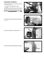
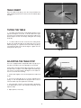
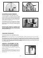
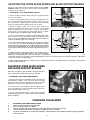
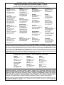
(28-293 & 28-299)
Model 28-293 Shown
PART NO. 426-02-651-0040 - 09-30-01
Copyright © 2001 Delta Machinery
To learn more about DELTA MACHINERY
visit our website at: www.deltamachinery.com.
For Parts, Service, Warranty or other Assistance,
please call
1-800-223-7278 (In Canada call 1-800-463-3582).
INSTRUCTION MANUAL
14" Wood Cutting
Band Saw
GENERAL SAFETY RULES
Woodworking can be dangerous if safe and proper operating procedures are not followed. As with all machinery, there are certain hazards involved with the operation of the product. Using the machine with respect and caution will considerably lessen
the possibility of personal injury. However, if normal safety precautions are overlooked or ignored, personal injury to the operator may result. Safety equipment such as guards, push sticks, hold-downs, featherboards, goggles, dust masks and hearing
protection can reduce your potential for injury. But even the best guard won’t make up for poor judgment, carelessness or inattention. Always use common sense and exercise caution in the workshop. If a procedure feels dangerous, don’t try it. Figure
out an alternative procedure that feels safer. REMEMBER: Your personal safety is your responsibility.
This machine was designed for certain applications only. Delta Machinery strongly recommends that this machine not be modified and/or used for any application other than that for which it was designed. If you have any questions relative to a particular application, DO NOT use the machine until you have first contacted Delta to determine if it can or should be performed on
the product.
Technical Service Manager
Delta Machinery
4825 Highway 45 North
Jackson, TN 38305
(IN CANADA: 505 SOUTHGATE DRIVE, GUELPH, ONTARIO N1H 6M7)
WARNING: FAILURE TO FOLLOW THESE RULES MAY RESULT IN SERIOUS PERSONAL INJURY!
17. REDUCE THE RISK OF UNINTENTIONAL STARTING.
Make sure switch is in “OFF” position before plugging in power
cord. In the event of a power failure, move switch to the
“OFF” position.
18. NEVER STAND ON TOOL. Serious injury could occur if the
tool is tipped or if the cutting tool is accidentally contacted.
19. CHECK DAMAGED PARTS. Before further use of the tool,
a guard or other part that is damaged should be carefully
checked to ensure that it will operate properly and perform its
intended function – check for alignment of moving parts, binding of moving parts, breakage of parts, mounting, and any other
conditions that may affect its operation. A guard or other part
that is damaged should be properly repaired or replaced.
20. DIRECTION OF FEED. Feed work into a blade or cutter
against the direction of rotation of the blade or cutter only.
21. NEVER LEAVE TOOL RUNNING UNATTENDED. TURN
POWER OFF. Don’t leave tool until it comes to a complete stop.
22. STAY ALERT, WATCH WHAT YOU ARE DOING, AND
USE COMMON SENSE WHEN OPERATING A POWER
TOOL. DO NOT USE TOOL WHILE TIRED OR UNDER THE
INFLUENCE OF DRUGS, ALCOHOL, OR MEDICATION. A
moment of inattention while operating power tools may result
in serious personal injury.
23. MAKE SURE TOOL IS DISCONNECTED FROM POWER
SUPPLY while motor is being mounted, connected or reconnected.
24. THE DUST GENERATED by certain woods and wood
products can be injurious to your health. Always operate
machinery in well ventilated areas and provide for proper dust
removal. Use wood dust collection systems whenever possible.
1. F O R Y O U R O W N S A F E T Y, R E A D I N S T R U C T I O N
MANUAL BEFORE OPERATING THE TOOL. Learn the tool’s
application and limitations as well as the specific hazards peculiar to it.
2. KEEP GUARDS IN PLACE and in working order.
3. ALWAYS WEAR EYE PROTECTION. Wear safety glasses.
Everyday eyeglasses only have impact resistant lenses; they
are not safety glasses. Also use face or dust mask if cutting
operation is dusty. These safety glasses must conform to
ANSI Z87.1 requirements. Note: Approved glasses have Z87
printed or stamped on them.
4. REMOVE ADJUSTING KEYS AND WRENCHES. Form
habit of checking to see that keys and adjusting wrenches are
removed from tool before turning it “on”.
5. KEEP WORK AREA CLEAN. Cluttered areas and benches
invite accidents.
6. DON’T USE IN DANGEROUS ENVIRONMENT. Don’t use
power tools in damp or wet locations, or expose them to rain.
Keep work area well-lighted.
7. KEEP CHILDREN AND VISITORS AWAY. All children and
visitors should be kept a safe distance from work area.
8. MAKE WORKSHOP CHILDPROOF – with padlocks,
master switches, or by removing starter keys.
9. DON’T FORCE TOOL. It will do the job better and be safer
at the rate for which it was designed.
10. USE RIGHT TOOL. Don’t force tool or attachment to do a
job for which it was not designed.
11. WEAR PROPER APPAREL. No loose clothing, gloves,
neckties, rings, bracelets, or other jewelry to get caught in moving parts. Nonslip footwear is recommended. Wear protective
hair covering to contain long hair.
12. SECURE WORK. Use clamps or a vise to hold work when
practical. It’s safer than using your hand and frees both hands to
operate tool.
13. DON’T OVERREACH. Keep proper footing and balance at
all times.
14. MAINTAIN TOOLS IN TOP CONDITION. Keep tools sharp
and clean for best and safest performance. Follow instructions
for lubricating and changing accessories.
15. DISCONNECT TOOLS before servicing and when changing accessories such as blades, bits, cutters, etc.
16. USE RECOMMENDED ACCESSORIES. The use of accessories and attachments not recommended by Delta may cause
hazards or risk of injury to persons.
WARNING: SOME DUST CREATED BY POWER
25.
SANDING, SAWING, GRINDING, DRILLING, AND OTHER
CONSTRUCTION ACTIVITIES contains chemicals known to
cause cancer, birth defects or other reproductive harm. Some
examples of these chemicals are:
· lead from lead-based paints,
· crystalline silica from bricks and cement and other
masonry products, and
· arsenic and chromium from chemically-treated lumber.
Your risk from these exposures varies, depending on how
often you do this type of work. To reduce your exposure to
these chemicals: work in a well ventilated area, and work with
approved safety equipment, such as those dust masks that
are specially designed to filter out microscopic particles.
SAVE THESE INSTRUCTIONS.
Refer to them often and use them to instruct others
2
ADDITIONAL SAFETY RULES FOR BAND SAWS
1.
IF you are not thoroughly familiar with the operation of
band saws, obtain advice from your supervisor, instructor, or
some other qualified person.
2.
Make sure wiring codes and recommended electrical
connections are followed and that tool is properly grounded..
3.
Make sure that the saw blade teeth point downward
toward the table.
4.
Adjust the upper guide about 1/8" above the work.
5.
Make sure that the blade tension and blade tracking are
properly adjusted.
6.
Stop the machine before removing scrap pieces from the
table.
7.
Always keep hands and fingers away from the blade..
8.
Check for proper blade size and type.
9.
Hold workpiece firmly against the table. DO NOT attempt
to saw stock that does not have a flat surface, unless a suitable
support is used.
10. Hold material firmly and feed into blade at a moderate
speed.
11. Turn off the tool if the material is to be backed out of an
uncompleted or jammed cut.
12.
Make “release cuts before cutting long curves.
13. Shut off power and clean the band saw and work area
before leaving the tool.
IMPORTANT: When the tool is not in use, the switch
should be locked in the “OFF” position to prevent unauthorized use.
14. ADDITIONAL INFORMATION regarding the safe and
proper operation of this product is available from the National
Safety Council, 1121 Spring Lake Drive, Itasca, IL 60143-3201 in
the Accident Prevention Manual for Industrial Operations and
also in the Safety Data Sheets provided by the NSC. Please also
refer to the American National Standards Institute ANSI 01.1
Safety Requirements for Woodworking Machinery and the U.S.
Department of Labor OSHA 1910.213 Regulations.†
CONNECTING TOOL TO POWER SOURCE
POWER CONNECTIONS
A separate electrical circuit should be used for your tools. This circuit should not be less than #12 wire and should be
protected with a 20 Amp time lag fuse. If an extension cord is used, use only 3-wire extension cords which have 3prong grounding type plugs and 3-hole receptacles which accept the tool’s plug. Before connecting the motor to the
power line, make sure the switch is in the “OFF” position and be sure that the electric current is of the same characteristics as indicated on the tool. All line connections should make good contact. Running on low voltage will damage
the motor.
WARNING: DO NOT EXPOSE THE TOOL TO RAIN OR OPERATE THE TOOL IN DAMP LOCATIONS.
MOTOR SPECIFICATIONS
Your tool is wired for 120 volt, 60 Hz. alternating current. Before connecting the tool to the power source, make
sure the switch is in the “OFF” position.
GROUNDING INSTRUCTIONS
WARNING: THIS TOOL MUST BE GROUNDED WHILE IN USE TO PROTECT THE OPERATOR FROM
ELECTRIC SHOCK.
3
1. All grounded, cord-connected tools:
2. Grounded, cord-connected tools intended for use on a
supply circuit having a nominal rating less than 150 volts:
In the event of a malfunction or breakdown, grounding provides a path of least resistance for electric current to reduce
the risk of electric shock. This tool is equipped with an electric
cord having an equipment-grounding conductor and a
grounding plug. The plug must be plugged into a matching
outlet that is properly installed and grounded in accordance
with all local codes and ordinances.
This tool is intended for use on a circuit that has an outlet that
looks like the one illustrated in Fig. 1. The tool has a grounding
plug that looks like the plug illustrated in Fig. 1. A temporary
adapter, which looks like the adapter illustrated in Fig. 2, may
be used to connect this plug to a matching 2-conductor receptacle as shown in Fig. 2 if a properly grounded outlet is not
available. The temporary adapter should be used only until a
properly grounded outlet can be installed by a qualified electrician. The green-colored rigid ear, lug, and the like, extending
from the adapter must be connected to a permanent ground
such as a properly grounded outlet box. Whenever the adapter
is used, it must be held in place with a metal screw.
Do not modify the plug provided - if it will not fit the outlet, have
the proper outlet installed by a qualified electrician.
Improper connection of the equipment-grounding conductor
can result in risk of electric shock. The conductor with insulation having an outer surface that is green with or without
yellow stripes is the equipment-grounding conductor. If
repair or replacement of the electric cord or plug is necessary, do not connect the equipment-grounding conductor to
a live terminal.
NOTE: In Canada, the use of a temporary adapter is not
permitted by the Canadian Electric Code.
Check with a qualified electrician or service personnel if the
grounding instructions are not completely understood, or if in
doubt as to whether the tool is properly grounded.
WARNING: IN ALL CASES, MAKE CERTAIN THE
RECEPTACLE IN QUESTION IS PROPERLY
G R O U N D E D . I F Y O U A R E N O T S U R E H AV E A
QUALIFIED ELECTRICIAN CHECK THE RECEPTACLE.
Use only 3-wire extension cords that have 3-prong grounding
type plugs and matching 3-conductor receptacles that accept
the tool’s plug, as shown in Fig. 1.
Repair or replace damaged or worn cord immediately.
GROUNDED OUTLET BOX
GROUNDED OUTLET BOX
GROUNDING
MEANS
CURRENT
CARRYING
PRONGS
ADAPTER
GROUNDING BLADE
IS LONGEST OF THE 3 BLADES
Fig. 1
Fig. 2
MINIMUM GAUGE EXTENSION CORD
EXTENSION CORDS
RECOMMENDED SIZES FOR USE WITH STATIONARY ELECTRIC TOOLS
Ampere
Rating
Use proper extension cords. Make sure your extension
cord is in good condition and is a 3-wire extension cord
which has a 3-prong grounding type plug and matching
receptacle which will accept the tool’s plug. When using
an extension cord, be sure to use one heavy enough to
carry the current of the tool. An undersized cord will
cause a drop in line voltage, resulting in loss of power
and overheating. Fig. 3, shows the correct gauge to use
depending on the cord length. If in doubt, use the next
heavier gauge. The smaller the gauge number, the
heavier the cord.
Volts
Total Length
of Cord in Feet
0-6
0-6
0-6
0-6
120
120
120
120
up to 25
25-50
50-100
100-150
18 AWG
16 AWG
16 AWG
14 AWG
6-10
6-10
6-10
6-10
120
120
120
120
up to 25
25-50
50-100
100-150
18 AWG
16 AWG
14 AWG
12 AWG
10-12
10-12
10-12
10-12
120
120
120
120
up to 25
25-50
50-100
100-150
16 AWG
16 AWG
14 AWG
12 AWG
12-16
12-16
12-16
120
120
120
up to 25
25-50
14 AWG
12 AWG
GREATER THAN 50 FEET NOT RECOMMENDED
Fig. 3
4
Gauge of
Extension Cord
OPERATING INSTRUCTIONS
FOREWORD
Delta Models 28-293 and 28-299 are 14" Band Saws. These tools are equipped with a 1 HP, 115V guarded drip-proof motor
inside an enclosed stand. Included with each saw is a push button switch, a blade and belt guard, an arbor and motor pulleys
with a V-belt, blade guides, a wood cutting blade, and an instruction manual.
UNPACKING AND CLEANING
Carefully unpack the tool and all loose items from the shipping container(s). Remove the protective coating from all unpainted
surfaces. This coating may be removed with a soft cloth moistened with kerosene (do not use acetone, gasoline or lacquer thinner
for this purpose). After cleaning, cover the unpainted surfaces with a good quality household floor paste wax.
NOTICE: THE MANUAL COVER PHOTO ILLUSTRATES THE CURRENT PRODUCTION
MODEL. ALL OTHER ILLUSTRATIONS ARE REPRESENTATIVE ONLY AND MAY NOT
DEPICT THE ACTUAL COLOR, LABELING, OR ACCESSORIES.
ASSEMBLY
STAND
The stand is shipped top-down in the shipping container
with the motor mounted to the inside top of the stand. The
on/off switch is wired to the end of the power cord.
To make the motor operational, do the following:
A
B
D
1. Remove the stand (A) Fig. 4 from the shipping container.
Be careful not to crimp the switch cord that extends through
the top of the stand. NOTE: Set the stand on several blocks
of wood to raise the stand off the floor.
2. Take the panel (B) Fig. 4 off of the stand (A) by removing
two screws (C) and loosening the two other screws (D).
Remove the panel on the opposite side of the stand in the
same way.
C
Fig. 4
G
H
3. Remove the two mounting screws that are holding the
motor (F) Fig. 5 to the top of the stand. One screw is shown
at (E) Fig. 5. IMPORTANT: DO NOT REMOVE THE CABLE
TIE (G) THAT HOLDS THE SWITCH CORD (H) TO THE
VERTICAL MOUNTING BAR (J), UNLESS THE ACCESSORY HEIGHT ATTACHMENT WILL BE USED ON THE
TOOL. THE CABLE TIE PREVENTS CONTACT BETWEEN
THE SWITCH CORD AND THE MOTOR PULLEY OR BELT.
J
F
E
Fig. 5
ATTACHING MOTOR TO STAND
1. Turn the stand on its side with the two bars (B) Fig. 6
down.
2. Position the motor (C), Fig. 6 on the two horizontal support bars (B), and fasten with the four 5/16x18 carriage bolts
and flanged nuts, two of which are shown at (D). IMPORTANT: PLACE THE MOTOR SHAFT (E) ON THE SAME
SIDE OF THE STAND AS THE LARGE OPENING AT THE
TOP OF THE STAND (SEE (B) FIG. 8) BEFORE LOOSELY
TIGHTENING THE CARRIAGE BOLTS (D). Further alignment will be necessary after the saw is attached to the
stand.
3.
Carefully turn the stand right side up.
Fig. 6
5
B
ATTACHING MOTOR PULLEY
Attach the motor pulley (A) Fig. 7 to the motor shaft, making
sure that the set screw (B) in the motor pulley engages with
the key (C) in the motor shaft. NOTE: The key is shipped
taped to the motor. Remove it, place it on the motor shaft
and then attach the pulley over it.
A
C
Fig. 7
A
B
A
ATTACHING BAND SAW
TO THE STAND
CAUTION: The band saw is very heavy. Use a helper
when attaching the saw to the stand.
Attach the band saw to the stand in the four holes provided
(two of which are shown at (A) Fig. 8). Place one 5/16 -18 x
1-3/4" hex head screw and one 5/16" flat washer through
each hole through the bottom of the band saw and the top
of the stand, and attach with a 5/16" lock washer, and 5/1618 hex nut.
Fig. 8
ATTACHING AND ALIGNING V-BELT,
ADJUSTING BELT TENSION
A
1. Attach the V-belt (E) Fig. 9 on the two pulleys (A and B),
and adjust the belt tension by raising or lowering the motor
(C) on the motor mounting bars (D). (If necessary, the motor
mounting bars (D) can be repositioned on the two posts (F).
Tension is correct when the belt is deflected approximately
1" in the center.
2. Place a straight edge against the belt along the Vgroove of both pulleys. Visually check to see that both
pulleys are in line. Either pulley can be moved in or out by
loosening the set screw (the lower pulley set screw is shown
at (B) Fig. 7). After aligning, tighten the set screw. The motor
can also be moved on the mounting bars.
E
F
C
B
D
Fig. 9
ATTACHING THE BELT
AND THE PULLEY GUARD
A
1. DISCONNECT TOOL FROM POWER SOURCE.
B
2. Attach the belt and pulley guard (A) to the top of the
stand (B) Fig. 10 using the two 1/4-20 x 1/2" hex head screws
(C) Fig. 10 through the top of the guard and the stand, and
attach those to 1/4" washers and 1/4-20 nuts (D) Fig. 10 from
the bottom.
C
D
Fig. 10
6
ATTACHING THE SWITCH
A push-button switch (mounted in a switch box), and a cord
set are supplied with the unit. To attach the switch to the band
saw arm, do the following:
1. DISCONNECT TOOL FROM POWER SOURCE.
2. CAUTION: The on/off switch-to-motor cord (F) Fig. 11 is
tied to the vertical mounting post (G) opposite the motor pulley.
This cable tie (H) prevents the switch-to-motor cord (F) from
contacting the belt or motor pulley during operation of the unit.
IMPORTANT: Leave this cable tie in place. Remove it ONLY
when using the Accessory Height Attachment with the tool.
Fig. 11
B
A
3. Remove the two outer hex nuts and lock washers (A) Fig.
12, from the two screws extending out from the back of the
switch box (B).
Fig. 12
D
4. Insert two screws (C) Figs. 13, located on back of switch
box, into two holes (D) located in the band saw arm.
C
Fig. 13
5. Use the two nuts and lockwashers (E) Fig. 14, removed in
STEP 3, to fasten the switch box to the bandsaw arm (Fig. 14).
E
Fig. 14
7
6. Remove the screw and cable clamp (E) Figs. 15 and 16 from
the lower arm of the band saw.
E
Fig. 15
7. Insert the switch cord (F) Fig. 16, into the clamp (E)
(removed in STEP 6), and fasten the switch cord (F) to the
bandsaw.
IMPORTANT: Be certain to prevent contact between the on/off
switch-to-motor cord (F) Fig. 16 and the motor pulley or belt. If
necessary, adjust the cord, then tighten the cable tie (H) Fig.11.
F
8. Attach the two side panels removed earlier.
E
Fig. 16
STARTING AND
STOPPING SAW
K
To start the tool, press the “START” button (K) Fig. 17. To stop
the tool, press the “STOP” button (L) Fig. 17.
L
Fig. 17
LOCKING SWITCH IN
THE OFF POSITION
IMPORTANT: When the tool is not in use, the switch
should be locked in the “OFF” position to prevent
unauthorized use, using a padlock (M) Fig. 18 with a
3/16" diameter shackle.
K
M
Fig. 18
8
TABLE INSERT
B
Place the table insert (A) Fig. 19 in the hole provided in the
table. Engage the protrusion on the insert in the indents (B) in
the table.
A
Fig. 19
TILTING THE TABLE
1. The table on the band saw can be tilted 45 degrees to the
right and 10 degrees to the left. To tilt the table to the right,
loosen the two locking knobs (A) Fig. 20, tilt the table to the
desired angle as shown on Scale (D)., and tighten two locking
knobs (A).
A
A
2. To tilt the table to the left, loosen the two locking knobs
(A) Fig. 20, and tilt the table to the right until access to the
table stop (A) Fig. 21 is gained. Remove the table stop (A) Fig.
19, and tilt the table to the left 10 degrees. Tighten the two
locking knobs (A) Fig. 20.
Fig. 20
ADJUSTING THE TABLE STOP
A
The tool is equipped with an adjustable table stop (A) Fig. 21
that allows the table to be set at 90 degrees to the blade.
B
Tilt the table to the right until the table stop (A) Fig. 21 contacts
the table. Place a square on the table against the blade (Fig.
22). Check to see if the blade is 90 degrees to the table surface. If not, then do the following:
C
1. Tilt the table slightly to the left and tighten the table lock
knobs.
Fig. 21
2. Loosen the locknut (B) Fig. 21 to free the adjustment nut
(A) Fig. 21. Turn the adjustment nut (A) right or left to raise or
lower the table stop, then tighten the locknut (B).
3. Lower the table. Check to see that the table is 90 degrees
to the blade (Fig. 22). If it is, then hold the stop (A) Fig. 21 and
tighten nut (B).
4. Adjust pointer, if necessary.
Fig. 22
9
A
A
Fig. 23
Fig. 24
ADJUSTING BLADE TENSION
CAUTION: DISCONNECT TOOL FROM POWER SOURCE.
A series of graduations is located on the back of the upper
wheel slide bracket. These graduations indicate the proper
tension for various widths of blades. With the blade on the
wheels, turn the knob (A) Fig. 21 to raise or lower the wheel,
until the red fiber washer (B) is in line with the proper graduation for the size of the blade used.
These graduations are correct for average work, and will not
be affected by rebrazing of the saw blade. Use these graduations until you become familiar enough with the operation
of the band saw to vary the tension for different kinds of
blades or work.
D
C
B
IMPORTANT: OVER-STRAINING IS A COMMON CAUSE
OF BLADE BREAKAGE AND OTHER UNSATISFACTORY
BLADE PERFORMANCE. RELEASE THE TENSION WHEN
THE TOOL IS NOT IN USE.
Fig. 25
TRACKING THE BLADE
CAUTION: DISCONNECT TOOL FROM POWER SOURCE.
IMPORTANT: Before tracking the blade, make sure that the blade guides and blade support bearings are clear of the blade.
After applying tension to the blade, rotate the wheels slowly forward by hand and observe the blade’s movement. The blade
(A) Fig. 24 should travel in the center of the upper tire. If the blade creeps toward the front edge, loosen the wing nut (B) Fig.
25, and tighten the thumb screw (C). This action draws the blade toward the center of the tire. If the blade creeps toward the
back edge, turn the thumb screw in the opposite direction. Adjust the thumb screw (C) Fig. 25 only a fraction of a turn each
time. NEVER TRACK THE BLADE WHILE THE TOOL IS RUNNING. After the blade is tracking in the center of the tires, tighten the wing nut (B) Fig. 25.
VERTICAL ADJUSTMENT OF THE
UPPER BLADE GUIDE ASSEMBLY
CAUTION: DISCONNECT TOOL FROM POWER SOURCE.
Readjust the blade guides and bearings according to the
following instructions.
Set the upper blade guide assembly (A) Fig. 26 as close as
possible to the top surface of the workpiece. Loosen the
lock knob (B) and move the guide assembly (A) to the
desired position.
B
A
Fig. 26
10
ADJUSTING THE UPPER BLADE GUIDES AND BLADE SUPPORT BEARING
Adjust the upper blade guides and blade support bearings ONLY
AFTER the blade has the correct tension and is tracking properly.
To adjust, do the following:
1. DISCONNECT TOOL FROM POWER SOURCE
C
2. Make sure that the bottom blade guides and support bearings
are clear of the blade.
B
A
3. Check the upper blade guide assembly. The blade guides (A)
Fig. 27 should be parallel to the blade. To adjust, loosen the screw
(B) and rotate the complete guide assembly (C). When the blade
guides are parallel with the blade, tighten the screw (B).
4. Adjust the guides (A) Fig. 28, so that the front edge of the
guides are just behind the “gullets” of the saw teeth. The complete
guide block bracket can be moved in or out by loosening the
thumb screw (C) and turning the knurled knob (D) Fig. 28. When
the guides (A) are set properly, tighten thumb screw (C).
Fig. 27
5. Two set screws (B) Fig. 28 hold the upper blade guides (A) in
place. Loosen the set screws (B) to move the guides (A). Place
them as close as possible to the side of the blade. (Be careful not
to pinch the blade). Tighten the screws (B).
F
G
H
E
6. The upper blade support bearing (E) Fig. 28 prevents damage
to the set in the saw teeth by keeping the blade from being
pushed too far toward the back. The support bearing (E) should be
set 1/64" behind the blade by loosening the thumb screw (F) and
turning the knurled knob (G) to move the support bearing (E) in or
out.
D
A
C
B
B
A
7. Adjust the blade support bearing (E) so that the back edge of
Fig. 28
the blade overlaps the outside diameter of the ball bearing by
about 1/16". The bearing (E) is set on an eccentric. To change the position, remove the screw (H) and bearing (E) Fig. 28.
Loosen the thumb screw (F), back out the knurled knob from the set screw. Remove the hex shaft from the hole, and rotate it
to move the eccentric for the bearing.
8. When the blade guide wears to a point that it cannot be adjusted close to the blade, loosen screw (B) Fig. 28 and reverse
the blade guides (A) Fig. 28.
ADJUSTING LOWER BLADE GUIDES
AND BLADE SUPPORT BEARING
Adjust the lower blade guides and blade support bearing after
the the upper guides and bearing have been adjusted.
B
A
B
A
1. DISCONNECT TOOL FROM POWER SOURCE.
2. Adjust the front edge of the guide blocks (B) so that they are
just behind the “gullets” of the saw teeth. Turn the knurled
knob (C) Fig. 29 to make this adjustment. Check the support
bearing. It should not be touching the back of the blade.
E
3. Loosen the two screws (A) Fig. 29. Move the guides (B) as
close as possible to the side of the blade, being careful not to
pinch the blade. Tighten screws (A).
D
C
3. Turn the other knurled knob (E) to adjust the lower blade
support bearing (D) Fig. 29 so that it is about 1/64" behind the
back of the blade.
Fig. 29
CHANGING THE BLADES
1.
2.
3.
4.
5.
6.
DISCONNECT TOOL FROM POWER SOURCE.
Open the upper and lower wheel guards.
Release tension on the saw blade.
Loosen the table alignment pin with a wrench and pull out. Remove table insert.
Take the blade off the wheel, and guide it through the slot in the table.
Install the new blade by reversing the procedure. (Table alignment pin should be seated by gently tapping it
with a hammer).
11
BAND SAW BLADES
A bandsaw blade is a delicate piece of steel that is subjected to a great deal of strain. Proper blade care results in
optimal performance. Always use blades of the proper thickness, width, and temper to correspond to the workpiece.
Use the widest blade possible. Narrow blades should be reserved for small, abrupt curves and delicate work.
When pressure is required to push a workpiece through the blade, either file and set the blade, or replace it. A broken
blade can be welded or brazed, but if the blade has been work-hardened, it will soon break again. A good rule of thumb
is to sharpen the blade after 4 hours of operation.
Band saw blades will break because of the peculiar stresses to which they are subjected. However, many blades break
because the operator (1) does not check the alignment and adjust the guides; (2) forces or twists the blade around a
short-radius curve; (3) feeds the workpiece too fast; (4) allows the blade to become dull; (5) tightens the blade tension
excessively; (6) sets the top blade guide too high; (7) uses a blade that has been improperly brazed or welded; and/or
(8) runs the blade continuously when not cutting.
Blades for the standard 14" Band Saw are 93-1/2" long. The saw can adjust to a maximum length of 94" and a minimum of 91-1/2". If the saw is equipped with the accessory Height Attachment, the blades should be 105" long.
Maximum and minimum lengths are 106" and 103-1/2".
OPERATING THE BAND SAW
CAUTION: DISCONNECT TOOL FROM POWER SOURCE.
Before starting the tool, make all adjustments and put all guards in place. Turn the upper wheel clockwise by hand to be sure
that everything is correct prior to turning the tool on.
Keep the top guide close to the work. Do not force the material against the blade.
Light contact with the blade will permit easier following of the line and will prevent excess friction, heating, and work-hardening of the blade at its back edge.
Keep the saw blade sharp and very little pressure will be required for average cutting.
Avoid twisting the blade by turning abrupt corners.
CUTTING CURVES
When cutting curves, turn the stock carefully so that the blade may follow without being twisted. If a curve is so abrupt that
repeated new kerfs are needed, then use either a narrower blade or one that has more set. The more set a blade has, the easier the stock is to turn. However, the cut is usually rougher than when using a medium set.
When withdrawing the blade, be careful not to draw the blade off of the wheels. In most cases, it is easier and safer to turn the
saw and saw out through waste material. Do not back the blade out while the saw is running.
ACCESSORIES
A complete line of accessories is available from your Delta Supplier, Porter-Cable • Delta Factory Service Centers,
and Delta Authorized Service Stations. Please visit our Web Site www.deltamachinery.com for a catalog or
for the name of your nearest supplier.
WARNING: Since accessories, other than those offered by Delta, have not been tested with
this product, use of such accessories could be hazardous. For safest operation,only Delta recommended accessories should be used with this product.
12
PARTS, SERVICE OR WARRANTY ASSISTANCE
All Delta Machines and accessories are manufactured to high quality standards and are serviced by a network
of Porter-Cable • Delta Factory Service Centers and Delta Authorized Service Stations. To obtain additional
information regarding your Delta quality product or to obtain parts, service, warranty assistance, or the location of the nearest service outlet, please call 1-800-223-7278 (In Canada call 1-800-463-3582).
Two Year Limited Warranty
Delta will repair or replace, at its expense and at its option, any Delta machine, machine part, or machine accessory which
in normal use has proven to be defective in workmanship or material, provided that the customer returns the product prepaid to a Delta factory service center or authorized service station with proof of purchase of the product within two years
and provides Delta with reasonable opportunity to verify the alleged defect by inspection. Delta may require that electric
motors be returned prepaid to a motor manufacturer’s authorized station for inspection and repair or replacement. Delta
will not be responsible for any asserted defect which has resulted from normal wear, misuse, abuse or repair or alteration
made or specifically authorized by anyone other than an authorized Delta service facility or representative. Under no circumstances will Delta be liable for incidental or consequential damages resulting from defective products. This warranty
is Delta’s sole warranty and sets forth the customer’s exclusive remedy, with respect to defective products; all other warranties, express or implied, whether of merchantability, fitness for purpose, or otherwise, are expressly disclaimed by Delta.
Printed in U.S.A.
13
NOTES
14
NOTES
15
PORTER-CABLE • DELTA SERVICE CENTERS
(CENTROS DE SERVICIO DE PORTER-CABLE • DELTA)
Parts and Repair Service for Porter-Cable • Delta Power Tools are Available at These Locations
(Obtenga Refaccion de Partes o Servicio para su Herramienta en los Siguientes Centros de Porter-Cable • Delta)
ARIZONA
Tempe 85282 (Phoenix)
2400 West Southern Avenue
Suite 105
Phone: (602) 437-1200
Fax: (602) 437-2200
CALIFORNIA
Ontario 91761 (Los Angeles)
3949A East Guasti Road
Phone: (909) 390-5555
Fax: (909) 390-5554
San Leandro 94577 (Oakland)
3039 Teagarden Street
Phone: (510) 357-9762
Fax: (510) 357-7939
FLORIDA
Davie 33314 (Miami)
4343 South State Rd. 7 (441)
Unit #107
Phone: (954) 321-6635
Fax: (954) 321-6638
Tampa 33609
4538 W. Kennedy Boulevard
Phone: (813) 877-9585
Fax: (813) 289-7948
GEORGIA
Forest Park 30297 (Atlanta)
5442 Frontage Road,
Suite 112
Phone: (404) 608-0006
Fax: (404) 608-1123
ILLINOIS
Addison 60101 (Chicago)
311 Laura Drive
Phone: (630) 628-6100
Fax: (630) 628-0023
Woodridge 60517 (Chicago)
2033 West 75th Street
Phone: (630) 910-9200
Fax: (630) 910-0360
MARYLAND
Elkridge 21075 (Baltimore)
7397-102 Washington Blvd.
Phone: (410) 799-9394
Fax: (410) 799-9398
MASSACHUSETTS
Braintree 02185 (Boston)
719 Granite Street
Phone: (781) 848-9810
Fax: (781) 848-6759
Franklin 02038 (Boston)
Franklin Industrial Park
101E Constitution Blvd.
Phone: (508) 520-8802
Fax: (508) 528-8089
MICHIGAN
Madison Heights 48071 (Detroit)
30475 Stephenson Highway
Phone: (248) 597-5000
Fax: (248) 597-5004
MINNESOTA
Minneapolis 55429
5522 Lakeland Avenue North
Phone: (763) 561-9080
Fax: (763) 561-0653
Cleveland 44125
8001 Sweet Valley Drive
Unit #19
Phone: (216) 447-9030
Fax: (216) 447-3097
MISSOURI
North Kansas City 64116
1141 Swift Avenue
P.O. Box 12393
Phone: (816) 221-2070
Fax: (816) 221-2897
OREGON
Portland 97230
4916 NE 122 nd Ave.
Phone: (503) 252-0107
Fax: (503) 252-2123
St. Louis 63119
7574 Watson Road
Phone: (314) 968-8950
Fax: (314) 968-2790
PENNSYLVANIA
Willow Grove 19090
520 North York Road
Phone: (215) 658-1430
Fax: (215) 658-1433
NEW YORK
Flushing 11365-1595 (N.Y.C.)
175-25 Horace Harding Expwy.
Phone: (718) 225-2040
Fax: (718) 423-9619
NORTH CAROLINA
Charlotte 28270
9129 Monroe Road, Suite 115
Phone: (704) 841-1176
Fax: (704) 708-4625
OHIO
Columbus 43214
4560 Indianola Avenue
Phone: (614) 263-0929
Fax: (614) 263-1238
TEXAS
Carrollton 75006 (Dallas)
1300 Interstate 35 N, Suite 112
Phone: (972) 446-2996
Fax: (972) 446-8157
Houston 77055
West 10 Business Center
1008 Wirt Road, Suite 120
Phone: (713) 682-0334
Fax: (713) 682-4867
WASHINGTON
Renton 98055 (Seattle)
268 Southwest 43rd Street
Phone: (425) 251-6680
Fax: (425) 251-9337
Authorized Service Stations are located in many large cities. Telephone 800-438-2486 or 731-541-6042 for assistance locating one.
Parts and accessories for Porter-Cable ·Delta products should be obtained by contacting any Porter-Cable·Delta Distributor, Authorized
Service Center, or Porter-Cable·Delta Factory Service Center. If you do not have access to any of these, call 800-223-7278 and you will
be directed to the nearest Porter-Cable·Delta Factory Service Center. Las Estaciones de Servicio Autorizadas están ubicadas en muchas
grandes ciudades. Llame al 800-438-2486 ó al 731-541-6042 para obtener asistencia a fin de localizar una. Las piezas y los accesorios
para los productos Porter-Cable·Delta deben obtenerse poniéndose en contacto con cualquier distribuidor Porter-Cable·Delta, Centro
de Servicio Autorizado o Centro de Servicio de Fábrica Porter-Cable·Delta. Si no tiene acceso a ninguna de estas opciones, llame al
800-223-7278 y le dirigirán al Centro de Servicio de Fábrica Porter-Cable·Delta más cercano.
CANADIAN PORTER-CABLE • DELTA SERVICE CENTERS
ALBERTA
Bay 6, 2520-23rd St. N.E.
Calgary, Alberta
T2E 8L2
Phone: (403) 735-6166
Fax: (403) 735-6144
BRITISH COLUMBIA
8520 Baxter Place
Burnaby, B.C.
V5A 4T8
Phone: (604) 420-0102
Fax: (604) 420-3522
MANITOBA
1699 Dublin Avenue
Winnipeg, Manitoba
R3H 0H2
Phone: (204) 633-9259
Fax: (204) 632-1976
ONTARIO
505 Southgate Drive
Guelph, Ontario
N1H 6M7
Phone: (519) 836-2840
Fax: (519) 767-4131
QUÉBEC
1515 ave.
St-Jean Baptiste,
Québec, Québec
G2E 5E2
Phone: (418) 877-7112
Fax: (418) 877-7123
1447, Begin
St-Laurent, (Montréal),
Québec
H4R 1V8
Phone: (514) 336-8772
Fax: (514) 336-3505
The following are trademarks of PORTER-CABLE·DELTA (Las siguientes son marcas registradas de PORTER-CABLE S.A.): BAMMER®,
INNOVATION THAT WORKS®, JETSTREAM®, LASERLOC®, OMNIJIG®, POCKET CUTTER®, PORTA-BAND®, PORTA-PLANE®, PORTERCABLE®, QUICKSAND®, SANDTRAP®, SAW BOSS®, SPEED-BLOC®, SPEEDMATIC®, SPEEDTRONIC®, STAIR-EASE®, THE PROFESSIONAL EDGE®, THE PROFESSIONAL SELECT®, TIGER CUB®, TIGER SAW®, TORQBUSTER®, WHISPER SERIES®, DURATRONIC™, FLEX™,
FRAME SAW™, MICRO-SET™, MORTEN™, NETWORK™, RIPTIDE™, TRU-MATCH™, WOODWORKER’S CHOICE™, THE AMERICAN
WOOD SHOP™ (design) , AUTO-SET™, B.O.S.S.™, BUILDER’S SAW™, CONTRACTOR’S SAW™, DELTA™, DELTACRAFT™, HOMECRAFT™, JET-LOCK™, KICKSTAND™, THE LUMBER COMPANY™ (design). MICRO-SET™, Q3™, QUICKSET II™, QUICKSET PLUS™,
SAFEGUARD II™, SANDING CENTER™, SIDEKICK™, UNIFENCE™, UNIGUARD™, UNIRIP™, UNISAW™, VERSA-FEEDER™ .
Trademarks noted with ™ and ® are registered in the United States Patent and Trademark Office and may also be registered in other countries. Las Marcas Registradas con el signo de ™ y ® son registradas por la Oficina de Registros y Patentes de los Estados Unidos y también pueden estar registradas en otros países.
Printed in U.S.A.