1
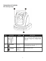
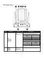
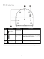
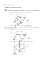
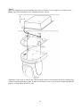
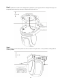
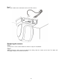
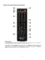
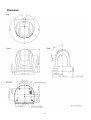
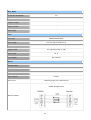
Full HD PTZ Camera
PTC-100
INSTRUCTION MANUAL
www.datavideo-tek.com
Contents
Warnings and Precautions ......................................................................................................... 3
Warranty..................................................................................................................................... 4
Disposal ..................................................................................................................................... 4
Packing List ................................................................................................................................ 4
Introduction ................................................................................................................................ 5
Product Overview ....................................................................................................................... 5
Features ..................................................................................................................................... 5
Connections & Controls.............................................................................................................. 6
PTC-100 Front View............................................................................................................ 6
PTC-100 Rear View ............................................................................................................ 7
PTC-100 Bottom View ......................................................................................................... 9
PTC-100 Installation Guide ............................................................................................... 12
OSD Operational Description ................................................................................................... 16
CAMERA SETUP > FOCUS SETUP ................................................................................ 19
CAMERA SETUP > EXPOSURE SETUP ......................................................................... 19
CAMERA > DAY/ NIGHT .................................................................................................. 20
CAMERA > WHITE BALANCE ......................................................................................... 21
CAMERA SETUP > NOISE REDUCTION ........................................................................ 21
CAMERA SETUP > EFFECT SETUP ............................................................................... 22
GROUP SETUP ................................................................................................................ 22
VIDEO SETP..................................................................................................................... 23
OSD SETUP ..................................................................................................................... 24
Remote Controller Button Description ...................................................................................... 27
Dimension ................................................................................................................................ 31
Specification ............................................................................................................................. 32
Service & Support .................................................................................................................... 36
R040546-DVv10
2
Warnings and Precautions
1.
Read all of these warnings and save them for later reference.
2.
Follow all warnings and instructions marked on this unit.
3.
Unplug this unit from the wall outlet before cleaning. Do not use liquid or aerosol cleaners. Use a damp
4.
Do not use this unit in or near water.
5.
Do not place this unit on an unstable cart, stand, or table. The unit may fall, causing serious damage.
6.
Slots and openings on the cabinet top, back, and bottom are provided for ventilation. To ensure safe and
cloth for cleaning.
reliable operation of this unit, and to protect it from overheating, do not block or cover these openings. Do
not place this unit on a bed, sofa, rug, or similar surface, as the ventilation openings on the bottom of the
cabinet will be blocked. This unit should never be placed near or over a heat register or radiator. This unit
should not be placed in a built-in installation unless proper ventilation is provided.
7.
This product should only be operated from the type of power source indicated on the marking label of the
AC adapter. If you are not sure of the type of power available, consult your Datavideo dealer or your local
power company.
8.
Do not allow anything to rest on the power cord. Do not locate this unit where the power cord will be
9.
If an extension cord must be used with this unit, make sure that the total of the ampere ratings on the
walked on, rolled over, or otherwise stressed.
products plugged into the extension cord do not exceed the extension cord’s rating.
10.
Make sure that the total amperes of all the units that are plugged into a single wall outlet do not exceed 15
11.
Never push objects of any kind into this unit through the cabinet ventilation slots, as they may touch
amperes.
dangerous voltage points or short out parts that could result in risk of fire or electric shock. Never spill
liquid of any kind onto or into this unit.
12.
Except as specifically explained elsewhere in this manual, do not attempt to service this product yourself.
Opening or removing covers that are marked “Do Not Remove” may expose you to dangerous voltage
points or other risks, and will void your warranty. Refer all service issues to qualified service personnel.
13.
Unplug this product from the wall outlet and refer to qualified service personnel under the following
conditions:
(1)
(2)
(3)
(4)
When the power cord is damaged or frayed;
When liquid has spilled into the unit;
When the product has been exposed to rain or water;
When the product does not operate normally under normal operating conditions. Adjust only those
controls that are covered by the operating instructions in this manual; improper adjustment of other
controls may result in damage to the unit and may often require extensive work by a qualified
technician to restore the unit to normal operation;
(5) When the product has been dropped or the cabinet has been damaged;
(6) When the product exhibits a distinct change in performance, indicating a need for service.
3
Warranty
Standard Warranty
• Datavideo equipment is guaranteed against any manufacturing defects for one year from the date of
purchase.
• The original purchase invoice or other documentary evidence should be supplied at the time of any
request for repair under warranty.
• Damage caused by accident, misuse, unauthorized repairs, sand, grit or water is not covered by this
warranty.
• All mail or transportation costs including insurance are at the expense of the owner.
• All other claims of any nature are not covered.
• Cables & batteries are not covered under warranty.
• Warranty only valid within the country or region of purchase.
• Your statutory rights are not affected.
Two Year Warranty
• All Datavideo products purchased after 01-Oct.-2008 qualify for a free one year extension to the standard
Warranty, providing the product is registered with Datavideo within 30 days of purchase. For information on
how to register please visit www.datavideo-tek.com or contact your local Datavideo office or authorized
Distributors
• Certain parts with limited lifetime expectancy such as LCD Panels, DVD Drives, Hard Drives are only
covered for the first 10,000 hours, or 1 year (whichever comes first).
• Any second year warranty claims must be made to your local Datavideo office or one of its authorized
Distributors before the extended warranty expires.
Disposal
For EU Customers only - WEEE Marking
This symbol on the product indicates that it should not be treated as household waste. It must
be handed over to the applicable take-back scheme for the recycling of waste electrical and
electronic equipment. For more detailed information about the recycling of this product, please
contact your local Datavideo office.
Packing List
Items
Description
Q’ty
1
PTC-100
1
2
Power Adaptor
1
3
Power Cord
1
4
Remote Controller (batteries included)
1
5
Bracket
1
6
Instruction Manual
1
4
Introduction
Thank you for purchasing the Datavideo PTC-100 Full HD PTZ Camera. We hope you will be pleased with your
purchase, and with what you can achieve with this camera. In order to get the most out of your camera, we
recommend that you spend some time getting familiar with this manual, as it will describe all the functions of this
unit. In addition, you’ll find some useful background information on how to install and set up this Pan, Tilt and
Zoom camera.
Product Overview
The PTC-100 has been designed with many indoor applications in mind such as live theatre events, concerts,
conferencing, worship, news studio, talk shows, education, indoor sports and security. The Datavideo PTC-100
combines outstanding image quality with super smooth and quiet pan/tilt/zoom operation. The PTC-100 produces
high quality video in a wide range of lighting conditions and supports 1080/30p,1080/59.94i, 1080/50i, 720/59.94p,
720/50p, as well as 480/59.94i (NTSC) and 576/50i (PAL).
The PTC-100 can be securely mounted in a variety of positions allowing its use in almost any location. Find new
creative shots and place this camera where the conventional cameraman cannot go such as on a ceiling, wall,
motorised dolly or even a camera boom.
When combined with the Datavideo RMC-180 a network of up to 4 PTC-100 cameras can be easily controlled by
one user. This camera also has an option to be controlled via RS-422 over an RJ45 connection allowing the
possibility of bespoke builds by system integrators. The camera also supports Pelco D/P; Sony VISCA protocols.
Features
HD Resolution (1080P): 1/3” SONY High Definition 3.0 MegaPixels CMOS sensor
High Sensitivity to support the low lux environment through “Exmor” technology
Line Focus Application can continue focusing when Zoom has been enabled
OSD Operation through IR/ RF Controller
Gamma Wide Dynamic Range (ATR-EX) function perfectly shows the image details between dark and
light. Newly added environment dynamic detection switch, enhancing WDR image efficiency.
Applied with Digital Noise Reduction Function (DNR) to reduce the noise and enable clearer image
under low light conditions.
Applied Digital Slow Shutter (DSS) to add the sensor sensitivity in low light conditions.
IR-Cut filter Removable (ICR) provides changes from color to BW mode automatically or manually for day
and night 24-hour surveillance.
Multi-language OSD (English, Simply Chinese and Traditional Chinese)
Low power Consumption to avoid the Hot Issue
Power ON/ OFF Application (Like Sleep mode)
Video Output: HD-SDI + CVBS + HDMI
Tally LED Design (IR/RF Controller/RS422/ DVIP Operation)
Supports Pelco D/P and SONY Visca Protocol Keyboard
DVIP Control Board with Daughter Board Design
5
Connections & Controls
PTC-100 Front View
Item
Illustration
3
Description
Lens
Built-in 1/3” Sony Exmor 3.0MP CMOS HD color
camera with white balance control, backlight
compensation settings, and automatic gain
settings etc.
Shown above
Tally LED
Tally lamp lights-up when tally signal has been
transmitted to the tally signal box.
Shown above
Sensor for the
Remote
Commander
Remote controller receiver.
1
2
Name
6
PTC-100 Rear View
Item
1
Illustration
Function
Description
SW2:
IRID&DVIP Setup
Bold letters indicates factory default value.
Setup
Switch Number
IRID
#1 #2
CAM 1
Off Off
On Off
CAM 2
Off On
CAM 3
On On
CAM 4
Setup
Switch Number
#3
Off
On
2
RS422
Communication
Control Input
Function
DVIP
RS422
Set #3 of SW2 to ON to connect RS422 and RJ45.
7
Item
Illustration
Function
Description
3
HD-SDI OUT
Video signal output 800mV+-10% 75Ω BNC
4
CVBS OUT
Video signal output CVBS 1. 0Vp-p 75Ω BNC
5
HDMI OUT
Video signal output16-bit YCbCr 4:2:2
DVIP
Communication
Control Input
Set #3 of SW2 to OFF to connect RJ45 and DVIP.
6
7
Power Input
Terminal
DC 12V Input, maximum power consumption is 2A
8
PTC-100 Bottom View
Item
1
Illustration
Shown above
2
3
Shown above
Function
Description
Tripod screw hole
SW1: DIP Switch
setup
PTZ cameras can be connected in series of up to
225 devices; each PTZ camera has its own ID
number and may not be repeated.
Screw Hole
Ceiling bracket mounting screw holes.
PTZ cameras can be connected in series 255; each PTZ camera machine must be set to the ID position.
9
SW1: ID Setup:
PTZ cameras can be connected in series of up to 225 devices; each PTZ camera has its own ID number
and may not be repeated.
10
DIP switch setting, as shown below:
Set to 000, then the image display will show: ID 1.
11
PTC-100 Installation Guide
Step 1
Set the IMAGE FLIP switch on the rear panel to ON.
Step 2
Attach the retaining wire to the junction box in the ceiling. Use a screw hole and a screw (not supplied) in the
junction box to attach the retaining wire.
Step 3
Attach the ceiling bracket (B) to the junction box on the ceiling. Make sure to align the holes in the bracket
with those in the junction box.
12
Step 4
Attach the ceiling bracket (A) to the bottom of the camera using the 3 screws. Align the screw holes on the
bottom of the camera with those in the ceiling bracket to the camera.
Tighten the screws a bit at a time in the numbered order shown in the illustration. Attach the retaining wire
using the screw designated as number ○
3 above. After all of the screws are inserted and temporarily tightened
properly, securely tighten each one in turn.
13
Step 5
Insert the protrusions raised on the ceiling bracket (A) into the spaces prepared in the ceiling bracket (B), and
temporarily attach them by pushing the ceiling bracket (A) to the rear.
Step 6
While pushing up on the front part of the camera, attach it using the three screws provided, starting with the
screw at position.
14
Step 7
Connect the cables to the connectors on the rear of the camera.
Removing the camera
Step 1
Remove the 3 screws used to attach the camera in step 6 of “Installation”.
Step 2
While pushing the entire camera up towards the ceiling, move the camera to the front. The hooks will
disengage, and you can remove the camera.
15
OSD Operational Description
◎ Selection marked as "*", represents factory default value
Menu Tree Structure
MAIN
MENU
MODE
ITEM
NOTES
DZOOM
ON/ OFF*
DEFAULT
Return to default setup
RETURN
Return to previous setup page
DZOOM
ON/ OFF*
DEFAULT
Return to default setup
RETURN
Return to previous setup page
DZOOM
ON/ OFF*
TRIGGER
Press to enable PUSH AUTO
DEFAULT
Return to default setup
RETURN
Return to previous setup page
BRIGHTNESS
-7> -6> -5 …> 0* > +1> …> +7
GAIN LIMIT
+6db* > +8db > +10db> …> +26db > +28db
SHUTTER
ON/ OFF*
WDR
ON/ OFF*
BLC
ON/ OFF*
DEFAULT
Return to default setup
RETURN
Return to previous setup page
BRIGHTNESS
-7> -6> -5 …> 0* > +1> …> +7
GAIN LIMIT
+6db* > +8db > +10db> …> +26db > +28db
SHUTTER
1/1> 1/2> …> 1/30* > 1/60> …> 1/6000> 1/10000 (NTSC)
1/1> 1/2> …> 1/25* > 1/50> …> 1/6000> 1/10000 (NTSC)
WDR
ON/ OFF*
DEFAULT
Return to default setup
RETURN
Return to previous setup page
BRIGHTNESS
-7> -6> -5 …> 0* > +1> …> +7
GAIN LIMIT
+6db* > +8db > +10db> …> +26db > +28db
IRIS
F14> F11> 9.6> …> F2.8> F2.4> F2> F1.6*
WDR
ON/ OFF*
DEFAULT
Return to default setup
RETURN
Return to previous setup page
FOCUS
AUTO*
MANUAL
PUSH AUTO
EXPOSURE
CAMERA
SETUP
AUTO*
SHUTTER
IRIS
16
DAY/ NIGHT
DEFAULT
Return to default setup
RETURN
Return to previous setup page
DEFAULT
Return to default setup
RETURN
Return to previous setup page
DEFAULT
Return to default setup
RETURN
Return to previous setup page
DEFAULT
RETURN
RED GAIN
Return to default setup
Return to previous setup page
AE
DAY*
NIGHT
WHITE BALANCE
AUTO*
BLUE GAIN
DEFAULT
RETURN
TRIGGER
PUSH AUTO
DEFAULT
RETURN
NOISE REDUCTION
MANUAL
CAMERA
SETUP
0> 1> 2> ...> 212*> 213> ...> 255
0> 1> 2> ...> 148*> 149> ...> 255
Return to default setup
Return to previous setup page
Press and will activate after 3 seconds
Return to default setup
Return to previous setup page
LEVEL
0*> 1> 2> 3> 4> 5
DEFAULT
Return to default setup
RETURN
Return to previous setup page
NEGATIVE
ON/ OFF* (This function is ineffective under night mode)
MIRROR
OFF*> LEVEL > ROTATE
FREEZE
ON/ OFF*
DEFAULT
Return to default setup
RETURN
Return to previous setup page
NUMBER
1> 2> 3> 4> 5> 6 > 7> 8
EFFECT SETUP
AUTOPAN INDEX 1> 2> 3> ...> 31> 32
PRESET NUMBER 0*> 1> 2> 3...> 31> 32
1> 2> 3> ...> 59> ...> 60*
SPEED (DPS)
DWELL TIME (SEC) 1> 2*> 3> ...> 126> 127
GROUP
SETUP
EXECUTE
Press to execute cruise function
DEFAULT
Return to default setup
RETURN
Return to previous setup page
VERTICAL
0>
1> ...> 96*> 97> ...> 198> 199
0> 1> ...> 36* > 37> ...> 98> 99
DEFAULT
Return to default setup
RETURN
Return to previous setup page
LEVEL
VIDEO
SETUP
*1080/ 59.94i
(NTSC)
17
1080/ 50i (PAL)
1080/ 29.97p
(NTSC)
1080/ 25p (PAL)
VIDEO
SETUP
720/ 59.94p
(NTSC)
720/ 50p (PAL)
720/ 29.97p
(NTSC)
720/ 25p (PAL)
OSD
SETUP
HORIZONTAL
0> 1> ...> 96*> 97> ...> 198> 199
VERTICAL
0> 1> ...> 36* > 37> ...> 98> 99
DEFAULT
Return to default setup
RETURN
Return to previous setup page
HORIZONTAL
0> 1> ...> 96*> 97> ...> 198> 199
VERTICAL
0> 1> ...> 36* > 37> ...> 98> 99
DEFAULT
Return to default setup
RETURN
Return to previous setup page
HORIZONTAL
0> 1> ...> 96*> 97> ...> 198> 199
VERTICAL
0> 1> ...> 36* > 37> ...> 98> 99
DEFAULT
Return to default setup
RETURN
Return to previous setup page
LEVEL
0> 1> ...> 96*> 97> ...> 198> 199
VERTICAL
0> 1> ...> 36* > 37> ...> 98> 99
DEFAULT
Return to default setup
RETURN
Return to previous setup page
LEVEL
0> 1> ...> 96*> 97> ...> 198> 199
VERTICAL
0> 1> ...> 36* > 37> ...> 98> 99
DEFAULT
Return to default setup
RETURN
Return to previous setup page
LEVEL
0> 1> ...> 96*> 97> ...> 198> 199
VERTICAL
0> 1> ...> 36* > 37> ...> 98> 99
DEFAULT
Return to default setup
RETURN
Return to previous setup page
LEVEL
0> 1> ...> 96*> 97> ...> 198> 199
VERTICAL
0> 1> ...> 36* > 37> ...> 98> 99
DEFAULT
Return to default setup
RETURN
Return to previous setup page
ID DISPLA
ON/ OFF*
TITLE DISPLAY
ON/ OFF*
TITLE EDIT
Maximum 15 characters
ZOOM RATIO
ON/ OFF*
LANGUAGE
ENGLISH*/繁體中文/ 簡體中文
DEFAULT
Return to default setup
RETURN
Return to previous setup page
DEFAULT
Return to default setup
RETURN
Return to previous setup page
18
CAMERA SETUP > FOCUS SETUP
Users can setup focus application. Factory settings as shown below:
FOCUS
MODE
DZOOM
TRIGGER
DEFAULT
RETURN
Auto
OFF
OFF
OFF
MODE:
This function is used for setting up focus mode, it can be set to Auto/ Manual/ Push Auto.
1. Auto: Select auto mode to enable automatic adjustment of the focus position.
2. Manual: Select manual mode to setup focus position manually.
3. Push Auto: Select push auto to adjust focus position TELE or WIDE, the preset value becomes AF
mode and returns to Manual Focus mode.
DZOOM:
Digital zoom can be set to ON/ OFF.
TRIGGER:
Select this function to enable PUSH AUTO setup, but setup option must first be set to option PUSH
AUTO.
DEFAULT:
Return to default setup.
RETURN:
Return to previous setup page.
CAMERA SETUP > EXPOSURE SETUP
Users can setup exposure application. Factory settings as shown below:
EXPOSURE
MODE
BRIGHTNESS
GAIN LIMIT
SHUTTER
IRIS
WDR
BLC
DEFAULT
RETURN
AUTO
0
+6db
OFF
OFF
F1.6
OFF
OFF
MODE:
It consists of 3 types of mode: IRIS/ AUTO/ SHUTTER (Default Setup: AUTO).
1. IRIS: Select iris as priority adjustment mode.
2. AUTO: System will auto detect its brightness and the backlight compensation is auto defined by the system.
3. SHUTTER: Select shutter as priority adjustment mode.
BRIGHTNESS:
Image brightness setup, setup range is 0~7. (Default Setup: 0).
<NOTE> This function will lock the settings on the BLC mode.
19
GAIN LIMIT:
Setup Gain Limit, setup range = 0~28 (Default Setup: 6).
SHUTTER:
Shutter Speed consist of 5 types of mode: NTSC: 1/1,1/2,1/30,1/60,1/10000 and PAL: 1/1,1/2,
1/25,1/60,1/10000 (Default Setup: 1/30).
IRIS:
Setup Iris value, iris setup range = F14~F1.6 (Default Setup: F1.6).
WDR:
Setup Effio double scan WDR function ON/ OFF.
BLC:
System will auto detect its brightness and the backlight compensation is auto defined by the system.
DEFAULT:
Return to default setup.
RETURN:
Return to previous setup page.
CAMERA > DAY/ NIGHT
Users can setup D/ N application. Factory settings as shown below:
DAY/ NIGHT
MODE
DAY
NIGHT
AE
DEFAULT
RETURN
DAY
OFF
OFF
OFF
OFF
MODE:
Three types of setup modes: AE/ DAY/ NIGHT (Default Setup: AE).
1. AE: According to DAY→ NIGHT and NIGHT→DAY (Threshold Value), it will auto switch to Color or
B/W.
2. DAY: Switch to color mode.
3. NIGHT: Switch to B/ W mode.
DAY:
The threshold color value changes (from color to B/ W) under AE mode (Default Setup: 11).
NIGHT:
The threshold color value changes (from B/ W to color) under AE mode.
AE:
According to DAY→ NIGHT and NIGHT→ DAY (Threshold Value).
DEFAULT:
Return to default setup.
RETURN:
Return to previous setup page.
20
CAMERA > WHITE BALANCE
Users can setup white balance application. Factory settings as shown below:
WHITE BALANCE
MODE
AUTO
MANUAL
PUSH AUTO
DEFUALT
RETURN
AUTO
OFF
OFF
OFF
OFF
MODE:
Three types of WB mode setup: AUTO/ MANUAL/ PUSH AUTO (Default Setup: AUTO).
AUTO:
System auto adjusts the white balance condition and maintains it, no matter how the environment changes.
MANUAL:
Set white balance to manual mode to manually adjust red or blue gain (Setup Value: 0~255), higher the
value darker the color.
PUSH AUTO:
PUSH AUTO ON: Enable auto tracing white balance.
PUSH AUTO OFF: Disable auto tracing white balance and record current white balance value.
DEFAULT:
Return to default setup.
RETURN:
Return to previous setup page.
CAMERA SETUP > NOISE REDUCTION
Users can setup noise reduction application. Factory settings as shown below:
NOISE REDUCTION
LEVEL
DEFAULT
RETURN
0
OFF
LEVEL:
Noise Reduction Level: 0~5. Higher the level, better the noise reduction performance (Default Setup: 0).
DEFAULT:
Return to default setup.
RETURN:
Return to previous setup page.
21
CAMERA SETUP > EFFECT SETUP
User can setup some image application and effect. Factory settings are as shown below:
EFFECT SETUP
NEGATIVE
MIRROR
FREEZE
DEFAULT
RETURN
OFF
OFF
OFF
OFF
NEGATIVE:
Negative effect can be set to ON/ OFF (Default Setup: OFF).
MIRROR:
Three Types of MIRROR mode: OFF/ HORIZONTAL/ ROTATE (Default Setup: OFF).
FREEZE:
Freeze function can be set to ON/ OFF (Default Setup: OFF).
DEFAULT:
Return to default setup.
RETURN:
Return to previous setup page.
GROUP SETUP
This function is designed to group the preset points in order. Each group is allowed to set up 32 preset points for
moving speed and retention time. The Auto Pan has a total of 8 setting groups.
GROUP SETUP
NUMBER
AUTOPAN INDEX
PRESET NUMBER
SPEED (DPS)
DWELL TIME (SEC)
EXECUTE
DEFAULT
RETURN
0
60
2
OFF
OFF
NUMBER:
Select and setup cruise function: 1~4 (Default Setup: 1).
AUTOPAN INDEX:
Setup AUTOPAN preset value 1~34 into groups.
PRESET NUMBER:
Setup desired preset points. If you do not wish to set all 32 preset points, set “0” as the last preset point.
<NOTE> “0” meaning to ignore the point after AUTOPAN points.
22
SPEED (DPS):
Setup the moving speed, higher the value faster the speed.
DWELL TIME (SEC):
Setup the dwell time after cruise function stops (Dwell Time Range: 1~127 Sec.).
EXECUTE:
Precede preset function.
DEFAULT:
Return to default setup.
RETURN:
Return to previous setup page.
VIDEO SETP
User can setup video application. Factory settings are as shown below:
VIDEO SETUP
MODE
HORIZONTAL
VERTICAL
DEFAULT
RETURN
1080/ 59.94i
96
36
OFF
MODE:
Eight types of video modes:
NTSC: 1080/ 59.94i, 1080/ 29.97p, 720/ 59.94p, 720/ 29.97p
PAL: 1080/ 50i, 1080/ 25p, 720/ 50p, 720/ 25p
HORIZONTAL:
Can setup and adjust horizontal viewing angle: 0~199 (Default Setup: 96).
VERTICAL:
Can setup and adjust horizontal viewing angle: 0~199 (Default Setup: 96).
DEFAULT:
Return to default setup.
RETURN:
Return to previous setup page.
23
OSD SETUP
OSD SETUP
ID DISPLAY
TITLE DISPLAY
TITLE EDIT
ZOOM RATIO
LANGUAGE
DEFAULT
RETURN
OFF
OFF
TITLE
OFF
ENGLISH
OFF
ID DISPLAY:
To reveal or hide ID, can be set to ON/ OFF.
TITLE DISPLAY:
To reveal or hide Title, can be set to ON/ OFF.
TITLE EDIT:
Enter a title name (maximum 15 characters).
ZOOM RATIO:
To reveal or hide ZOOM RATIO, can be set to ON/ OFF.
LANGUAGE:
Supports three types of languages: ENGLISH/ 繁中/ 簡中.
DEFAULT:
Return to default setup.
RETURN:
Return to previous setup page.
24
25
26
Remote Controller Button Description
Menu Setup
PTC-100 requires HDMI monitor to browse the current setup status, and operation setup using keyboard or
remote controller buttons: MENU/ UP/ DOWN/ LEFT/ RIGHT/ A/FOCUS.
Setup methods of all menu function items are similar. Press the MENU button to enter or exit camera
menu options, press UP or DOWN arrow button to select the menu option. Use LEFT or RIGHT arrow
button to enter sub-menu option or press A/ FOCUS button to exit sub-menu option. Then use the LEFT or
RIGHT arrow button to change the value of the selected item or option.
27
Item
1
2
3
Illustration
Function
Description
Color Bar Setup
(MODE)
Use the MODE button to setup and adjust
the screen brightness and color density.
PAN/ TILT Control
(RESET)
Press RESET button to face the camera
back to the front.
Camera Select
(CAM1~CAM4)
Operating more than one camera with
the Remote Controller.
4
Position Setup
(0~9)
(PRESET)
(SET)
Set the IRID (SW2) switch (at the rear of
the main unit) of the camera which you
intend to operate: 1/ 2/ 3.
Press a CAMERA SELECT (CAM 1~ CAM
4) button (on the Remote Controller) which
corresponds to the number set in step 1.
After the above setup you will be able to
operate the camera (s) specified by
number.
Up to 32 combinations of settings (position,
zooming, focusing, gain control and iris
control) can be preset.
Adjusting the Preset Point
Adjust the position, the zooming, the
focusing, the gain control and the iris control
of the camera.
Setting up the Preset Point
Press any of the POSITION buttons 1~32
and then press SET button.
Recalling the memorized setting
Press any of the POSITION buttons 1~32
and then press PRESET button.
Setting up the Group Scan mode
Press any of the POSITION buttons 1~8
and then press MENU button.
To face the camera back to the front
Press the number 0 and then preset button.
5
Focus Setup
(FAR)
(NEAR)
To focus the camera on a subject
manually
Press either FAR or the NEAR button to
have the camera focus on the subject
manually.
28
Item
Illustration
Function
Description
Auto Focus Control
(A/ FOCUS)
To focus the camera on a subject
automatically
Press the A/ FOCUS button. The camera
focuses on the subject at the center of the
screen automatically.
6
Exit Sub-Menu Option
Press A/ FOCUS button to exit sub-menu
option.
7
Brightness Control
(A/ Gain)
(GAIN+)
(GAIN-)
When shooting a subject within a dark
environment
Press GAIN+ button brighten-up or GAIN- to
darken the environment.
To cancel the function or to return to
default setup, press the A/ GAIN button.
8
TALLY Lamp Control
(OPT1~OPT2)
9
Auto Iris Control
(A/ IRIS)
(IRIS+)
(IRIS-)
To make the subject appear brighter
Adjust the iris opening (aperture), to control
the amount of light coming through the lens
(ie. the "exposure"). Press IRIS+ button to
open the iris, more light comes in and the
subject appears brighter and IRIS- vice
versa.
To cancel the function or to return to
default setup, press the A/ IRIS button.
Switching the Pan/ Tile Speed
Press SPEED button to switch to diffent
speed (High/ Low).
10
11
Direction Arrows
(UP/ DOWN/ LEFT/
RIGHT)
To change direction of the camera
Press the arrow function to change the
directions of the camera head.
Stop Preset Point Auto Scan mode
Press any of the DIRECTION buttons.
Select Menu Option
Press UP or DOWN button to select the
menu option.
Enter Sub-Menu Option
Press LEFT or RIGHT button to enter submenu option.
Adjust Setup Value
Press LEFT or RIGHT button to adjust the
setup value.
29
Item
Illustration
Function
Description
12
Enter/ Exit Camera
Menu Option
Enter or Exit Camera Menu Option
13
Zoom in/ Zoom Out
Button
Enlarge Image (TELE)
Minimize Image (WIDE)
Zooming
Press either TELE button to zoom-in when
the subject appears close to the camera or
WIDE button to zoom-out when the subject
appears far away from the camera.
14
Speed Button
(FAST/ SLOW)
Switching the Zoom In/ Out Speed
Press this button to switch to diffent speed
(High/ Low).
15
Power Button
Switching Remote Controller ON/ OFF
30
Dimension
31
Specification
Item No.
Description
PTC-100 SD/ HD
HD-SDI/HDMI + CVBS PTZ Camera
Video
Image Device
1/3” Sony Exmor 3.0MP CMOS sensor
Picture Elements
Approx. 3M (1920H × 1080V)
Resolution
SD / HD / FHD
Signal system
480i (CBS)
576i (CBS)
720_50p/720_59.94p/
720_25p/720_29.97p/
1080_50i/1080_59.94i/
1080_25p/1080_29.97p
Min. Illumination
Less than 3.0 lx (F1.6, 50 IRE)
S/N Ratio
More than 50 dB
Electronic Shutter
1/1 to 1/10,000 s, 22 steps
Gamma
0.45
Iris Control
Auto / Manual
Wide Dynamic Range
On / Off
Digital Noise Reductions
On / Off (2D)
AE / Day / Night
Day & Night (ICR)
(Default: Day)
Day & Night I/O
On-Screen-Display (OSD)
English / Simplified Chinese / Traditional Chinese
OSD Control
IR Controller
Digital Slow Shutter (DSS)
On / Off
Flickerless Mode
50Hz~60Hz
(Bending Fixed)
32
Motion Detection
-
MD Sensitivity
-
Alarm
-
Privacy Masking
-
White Balance
Auto(ATW) / Manual / Push Auto
Auto/Manual
Gain Control
(6 to 28 dB, 2 dB steps)
Back Light Comp.
On / Off
Digital Zoom
12X
Mirror
Horizontal / Rotate
Freeze
On / Off
Positive / Negative
On / Off
Color Bar
On / Off (Full Bar)
Power Sleep Design
Yes
Pan / Tilt / Zoom
Mini. Shutting Distance
-
Panning/Tilting Range
Pan: ±173° , Tilt: +90° to -30°
Panning/Tilting Speed
Manual:1~60°/Sec
(100 step)
Preset: 60°/Sec
Focus Mode
Auto / Manual / Push Auto
Preset
32 Position
Coordinate
X, Y, Z
PTZ Mode
8 Group
Camera ID
0~255
Camera Title
Up to 15 characters
Initializing Time
40 sec
33
Day / Night
IR-Cut filter Removable
Yes
IR Distance
-
LED (pcs/angle)
-
Light Transistor
-
Wavelength
-
Lens
Lens Type
Mototized 20X Zoom
Focal Length
f=4.7 mm (W) to 94.0 mm (T)
Aperture Range
F1.6 to F3.5
Angle of View
54.1°(W-end) to 2.9°(T-end)
Aspect ratio
16 : 9
Lens Control
DC / Manual
Others
Weather Proof
-
Vandal Proof
-
Bracket
Yes
Sync. System
IR Receiver
Internal
Two IR Receiver in the Front of PTZ
RS422 through RJJ45
Remote Control
34
Protocol
Pelco D/ P; Sony VISCA
Baud Rate
9600bps
Video Output (HD)
HD-SDI (BNC)/ HDMI
Video Output (SD)
BNC
Video Format Output
1Vp-p/ 75Ohms.
Audio
-
FAN
-
Heater
-
Tally LED
Dimension (incl. BNC)
2 LED Built in the PTZ Zoom Module Side
218mm (H) x 173mm (W) x 185.5mm (D)
Weight
2.25 Kg
DC12±10%
Power Supply
Including the “Anti-Drop” design
Power Consumption
26W
0°C~50°C
Operating Temperature
Certifications
CE/ FCC Class A
Accessories
PTZ Bracket; IR/ RF Controller
Other
DVIP Control Board (Daughter Board Design)
35
Service & Support
It is our goal to make your products ownership a satisfying experience. Our supporting staff is available to assist
you in setting up and operating your system. Please refer to our web site www.datavideo-tek.com for answers to
common questions, support requests or contact your local office below.
Datavideo Global Website: www.datavideo-tek.com
Datavideo Corporation
Tel: +1 562 696 2324
Fax: +1 562-698-6930
E-Mail: [email protected]
Datavideo Technologies Europe BV
Tel: +31-30-261-96-56
Fax: +31-30 261-96-57
E-Mail: [email protected]
Fax: +44 1457 850 964
E-Mail: [email protected]
Datavideo UK Limited
Tel: +44 1457 851 000
Datavideo Technologies Co., Ltd
Tel: +886 2 8227 2888
Fax: +886-2-8227-2777
E-mail: [email protected]
Datavideo Technologies China Co., Ltd
Tel: +86 21-5603 6599
Fax:+86 21-5603 6770
E-mail: [email protected]
Datavideo Technologies (S) PTE LTD
Tel: +65-6749 6866
Fax: +65-6749 3266
E-mail: [email protected]
Fax: +852-2833-9916
E-mail: [email protected]
Fax: +33 1 60 37 67 32
E-Mail: [email protected]
Fax: +91 120 4309121
E-Mail: [email protected]
Datavideo HK Limited.
Tel: +852 2833 1981
Datavideo France
Tel: +33 1 60 37 02 46
Datavideo India
Tel: +91 120 4309120
All the trademarks are the properties of their respective owners.
Datavideo Technologies Co., Ltd. All rights reserved 2018
P/N: G082060582E1
36