1
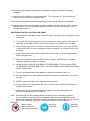
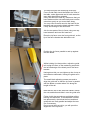
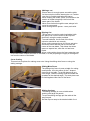
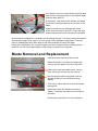
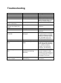
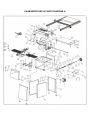
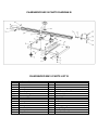
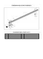
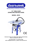
8” TABLE SAW
OPERATORS MANUAL
MODEL: W619
Charnwood, Cedar Court, Walker Road,
Hilltop Industrial Estate, Bardon Hill, Leicestershire, LE67 1TU
Tel. 01530 516 926 Fax. 01530 516 929
email: [email protected] website: www.charnwood.net
GENERAL SAFETY RULES
WARNING: Do not attempt to operate the machine until you have read thoroughly and
understood completely all instructions, rules, etc. contained in this manual. Failure to
comply may result in accidents involving fire, electric shock, or serious personal injury. Keep
this owner's manual and review frequently for continuous safe operation.
Know your machine. For your own safety, read the owner's manual carefully. Learn its
application and limitations, as well as specific potential hazards pertinent to this machine.
1. Make sure all tools are properly earthed.
2. Keep guards in place and in working order. If a guard must be removed for
maintenance or cleaning, make sure it is properly replaced before using the
machine again.
3. Remove adjusting keys and spanners. Form a habit of checking to see that the
keys and adjusting spanners are removed from the machine before switched it
on.
4. Keep your work area clean. Cluttered areas and workbenches increase the
chance of an accident.'
5. Do not use in dangerous environments. Do not use power tools in damp or wet
locations, or expose them to rain. Keep work areas well illuminated.
6. Keep children away. All visitors should be kept a safe distance
7. from the work area.
8. Make workshop childproof. Use padlocks, master switches
starter keys.
and remove
9. Do not force the machine. It will do the job better and be safer at the rate for
which it is designed.
10. Use the right tools. Do not force the machine or attachments to do a job for which
they are not designed. Contact the manufacturer or distributor if there is any
question about the machine's suitability for a particular task.
11. Wear proper apparel. Avoid loose clothing, gloves, ties, rings, bracelets, and jewellery
which could get caught in moving parts. Non-slip footwear is recommended. Wear
protective hair covering to contain long hair.
12. Always use safety glasses. Normal spectacles only have impact resistant lenses.
They are not safety glasses.
13. Do not over-reach. Keep proper footing and balance at all times.
14. Maintain the machine in good condition. Keep the machine clean for best and safest
performance. Follow instructions for lubrication and changing accessories.
15. Disconnect the machine from power source before servicing and when changing
the blade.
16. Never leave the machine running unattended. Turn the power off. Do not leave the
machine until it comes to a complete stop.
17. Do not use any power tools while under the effects of drugs, alcohol or medication.
18. Always wear a face or dust mask if operation creates a lot of dust and/or chips. Always
operate the tool in a well ventilated area and provide for proper dust removal. Use a
suitable dust extractor.
ADDITIONAL RULES FOR CIRCULAR SAWS
1. Ensure that the saw table is clear of off-cuts, tools or anything else that might foul the
work-piece.
2. If your saw has a dust extractor hose connected to the crown guard, ensure that it is
held clear of the table and will not foul the work-piece as it passes over the table.
3. When cutting large sheets of material or long boards use one or more roller stand(s)
to support the work or have a competent helper to support it as it feeds off the rear of
the table.
4. Never use the saw without the riving knife and check that it is in line with the blade
before using the saw.
5. Always use a brush to clear the table of dust or debris. NEVER use your hands,
especially when the machine is running.
6. ALWAYS USE A PUSH STICK WHEN IT IS NECESSARY TO PUSH ANY PIECE
OF MATERIAL OF SUCH SIZE THAT IT WOULD BRING YOUR HANDS WITHIN 30
CM OF THE BLADE.
7. Do not cut material that is badly warped or which has screws or nails in it
8. Be extra vigilant when cutting stock which has loose knots in it as these my fly out of
the saw.
9. NEVER remove the table insert when the saw is running.
10. To avoid exposure to hazardous dust, do not use this saw without connecting it to a
suitable dust extractor.
11. Always work with a sharp saw blade and feed the work at a rate suites to the
thickness and hardness of the material.
Note: This table saw has been designed and built solely as a woodworking machine.
Do not modify it in any way or use for anything other than its designated purpose.
Neither the manufactures nor the supplies are liable for any damage or injury caused
by incorrect assembly, operation or electrical connection of this machine.
Important:
Risk of Injury!
Wear Eye
Wear Ear
Never reach into
Protection
Protection
the running saw blade.
Specification
Table size
Table size with extensions
Motor (Induction)
Blade diameter x bore
Blade rotation speed (no load)
Maximum depth of cut at 90/45 degrees
Cutting width with table extension
Cutting width without table extension
Dust extractor hose connection
Weight
Rating
535 x400mm
535 x 1000mm
1100W, 240v
200mm x 30mm
4700 rpm
60mm /40mm
750mm
150mm
100mm
45kg
Light Trade
Rating Description
Light Trade: Suitable for professional woodworkers where the machine will not be in daily
use.
Mid range machines with a heavier build and more power. Typically used by 2 or 3 people
within a small business and also for the dedicated hobbyist with a larger budget. It is
expected to be used up to the machines maximum limit with occasional long work periods.
Suitable for income generation. Expected maximum use of 300 hours annually.
Unpacking
This product is packed into 2 parts; 1 wooden crate and 1 long cardboard carton.
Cut the straps and remove the lid of the crate
from the base.
Remove the plastic cover and the items
packed loosely around the base.
Remove two bolts holding the machine to the
pallet.
Lay the saw onto its side to remove further
items which are packed inside the floor stand
of the machine.
The second package, the long carton,
contains 5 aluminium extrusions.
Assembly
While the machine is on its side, take the four
feet from the bag of parts and screw them into
the four holes in the base. These feet can be
adjusted by means of a spanner to level the
saw table after the machine has been put into
place.
Return the saw to a vertical position.
The cast iron table is coated with a layer of grease to prevent rust. This is easily removed
with a soft cloth moistened with paraffin or WD40.
Raise the saw blade by turning the fitted hand
wheel at the front of the machine clockwise.
Fit the other hand wheel from the bag of
components to the spindle on the right hand side
of the saw. Tighten the grub screw so that it
engages with the flat on the spindle.
Turn the wheel clockwise until the blade is
vertical, if it is not already in this position.
There are two brackets at the front of the saw
table and a similar pair at the back.
Each one has two hex headed bolts and nuts
passing through it and a small black adjuster at
the back.
Loosen the nuts and lifting each bolt head in turn,
slide one of the 100cm long square aluminium
extrusions over them.
The extrusion with the measuring scale (Rip
Fence Guide Rail) should be fitted to the front of
the table, scale uppermost and in both cases the
open side should face outwards.
If they are difficult to slide on, make sure that you
have slackened the nuts sufficiently and rock the
extrusions gently as you move them along.
You may need to reach round to the back of the
brackets and unscrew the black adjusters a little,
if they are binding on the aluminium.
Join the two parts of the rip fence using one cap
head setscrew and one hex head bolt.
Place the rip fence over the front guide rail, so the
lip of the fence bracket sits behind the rail.
Position the rip fence parallel to and up against
the saw blade.
Whilst holding it in that position, adjust the guide
rail to align the 0cm on the measuring scale with
the left hand edge of the black part of the fence
bracket.
Having done this you can tighten up the 4 nuts on
the brackets underneath, locking the guide rail in
place.
The small black adjusting screws are used to
align the guide rail so that the rip fence is parallel
with the blade no matter where it is along the
length of the rail.
Now take the first of the extension tables, loosen
the nuts and bolts and slide it onto the guide rails.
Follow it with the second one and tighten all the
locking nuts and bolts. If the tables do not slide
into place easily, check that the front and back
guide rails are really parallel and adjust the rear
one if necessary.
Do not move the front rail or you will upset the
alignment of the rip fence.
Slide the hose support clip onto the rear guide rail
and lock it into place.
Fit the dust collection hose to the saw guard and
the spigot on the rear extraction point. Secure in
place with the two hose clamps provided.
Clip the hose into the support arm to hold it clear
of the table.
It is strongly recommended you use a dust
extractor at all times, by connecting a hose to
the 100mm outlet.
Failure to use an extractor will require
stopping the machine regularly to clean out of
the internal parts of the extraction hood, to
avoid causing damage.
Fit the two support arms which will carry the guide
rail for the sliding carriage.
These are bolted to the left hand side of the table
with four countersunk bolts. Fit the wide guide rail
extrusion by sliding it over the heads of the eight
securing bolts.
Position the sliding carriage guide rail so that the
back edge of the rail is level with the back side of
the rear guide rail. Ensure the guide rail is parallel
to the saw blade before tightening the eight nuts.
Before fitting the sliding carriage it should be
noted that the two outboard bearing wheels are
mounted on eccentrics.
Should it ever be necessary their position can be
adjusted with the aid of a 14 mm spanner.
The guide rail is fitted with front and rear travel
stops.
Move the rear travel stop to the back of the slot.
Remove the front stop completely and fit the
sliding carriage onto the guide rail so that the four
bearing guides are located in the matching
grooves along the sides of the rail.
Replace the front stop.
Identify the crosscut fence. Place it with the open
side, face down and the plastic tip to the right.
Slide the pivot block and the locking block onto
the back side of the fence with the head of the
bolt in the T-slot.
The Locking block has a T-shaped foot plate,
slide it into the slot in the sliding carriage table.
The Work clamp passes through the pivot block
and locates in the large hole at the front of the
carriage.
The work clamp should be locked in place using a
small grub screw in the front edge of the carriage.
Fit the flip-over length stop by feeding the head of
the bolt into the T-shaped slot on the top side of
the fence.
The ratchet handle locks the stop in place.
The stop plate can be flipped over to engage or
disengage it.
From underneath the carriage, push up the
locating stop.
Use a square to check the crosscut fence is set at
90 degrees to the blade.
If necessary, adjust the stop by loosening the
locking ring and grub screw. Put a screwdriver
into the slot to rotate the stop to set the angle.
Check the Sliding carriage is level to the main
table. It should also be slightly higher (up to 1mm)
than the main table to allow a clamped work piece
to move across the main table.
If necessary, loosen and adjust the four silver
support brackets to lift or level the sliding carriage.
The sliding mitre fence can be used on either side
of the blade.
Slide the T-shape bar in the slot in the main table.
The large knob is used to unlock the angle, which
can be read from the scale on the front.
Using the Table Saw
Rip Fence
Mitre Fence
Blade Angle Adjuster
Blade Angle Lock
Blade Height Adjuster
Work clamp
Sliding Carriage
On/Off Switch
Work Stop
Adjustable Feet
On/Off Switch
Slide the red section upwards and then lift the hinged cover. This will give you access to the
green start and red stop buttons. Pressing the red section of the cover will stop the saw.
To turn the saw on, press the green button. Wait for the blade to reach its maximum speed
of rotation before commencing with the cut.
The machine is fitted with an NVR (No Voltage Release) switch. This type of switch is
designed so that if the machine is disconnected from the mains whilst running and then
reconnected, the motor will not automatically restart.
Blade Height
Adjustments to the blade height should be made only when the saw is not running.
Turn the round hand wheel on the front, to set the blade to the required depth. Turn
anticlockwise to lower the blade, turn clockwise to raise the blade. The blade height should
always be set so that only the carbide tips of the blade (approx. 5mm) projects above the
wood.
Blade Angle
Adjustments to the angle of cut should be made only when the saw is not running.
To tilt the blade for making bevel cuts, undo the blade angle lock, rotate the hand wheel to
the required angle using the scale provided for guidance. Lock the angle by pressing down
the locking lever.
Making a cut
Ensure there is enough space around the table
for the work piece before starting the cut. Position
your feet in a stable and balanced stance.
When feeding the timber, place your hands on the
section of timber being kept. Never hold the
waste part of the timber.
Never force timber through the saw, always let it
cut at its own speed.
When cutting narrow pieces - use a push stick.
Ripping Cut
The rip fence is used to make longitudinal (with
the grain) cuts. Set the fence to the required
dimension using the scale provided.
To avoid kickback, the far end of the fence
extrusion should be set correctly.
When cutting narrow pieces, the fence extrusion
should be set so that the end is level with the
centre of the saw blade. This allows the timber
space to expand into, after the cut has been
made.
When cutting wider pieces the fence extrusion can
be moved further towards the back of the blade, in a line projecting at roughly at 45 degrees
out from the centre of the blade.
Cross Cutting
This saw has 2 options for making cross cuts: Using the sliding mitre fence or using the
sliding carriage.
Sliding Mitre Fence
The sliding mitre fence is most suitable for cutting
small pieces. It fits into either of the T-shaped
channels in the table. To set 90 degrees or any
other angle, undo the locking knob and rotate the
quadrant to the desired angle. The work piece can
be held against either face of the fence.
Sliding Carriage
The sliding carriage is more suitable when
working with large flat panels.
To use the sliding carriage pull the table all the
way forward.
Set the flip over stop to the desired width of cut.
If an angle is to be cut, undo the thumb screw and
ratchet lever, swing the fence to the desired angle
and lock them both off.
If necessary, undo both thumb screws and adjust
the fence so that the plastic tip is just clear of the
blade.
Load the wood onto the carriage and screw
down the work clamp to secure it. Press the start
button and push the wood through the saw blade.
An alternative configuration is available for the sliding carriage. The fence can be assembled
onto the back edge of the table in a mirror image of the standard configuration. The work
piece is loaded against the back edge of the fence and then fed onto the blade.
Using this configuration, the crosscut capacity can be increased and the sliding carriage
guide rail can be moved backwards so that it does not obstruct the operator.
Blade Removal and Replacement
Unplug the saw from the power source.
Raise the blade to its maximum height and
remove the saw guard from the riving knife.
Remove the right hand table insert, using a
4mm Hex key to remove the two screws.
Use the special spanner supplied, lock the
spindle by fitting it over the black locking
washer.
Then use a 13mm spanner to undo the blade
locking bolt.
Remove the bolt, flat washer and locking
washer. The blade can now be removed from
the shaft.
Reverse this procedure to fit the new blade.
Troubleshooting
Problem
Machine does not start
Cause
Blown Fuse
Loose switch terminal
Faulty switch
Doors not closed
Only starts when Green
button is held down
Machine does not run but
buzzing noise heard from
motor
Saw vibrates
Faulty switch
Cuts are slow, wood is
blackened
Saw stalls
Wood binds on rear of saw
blade
Lower saw guard fills with
dust
Blade tilt or blade height
difficult to adjust
Failed capacitor
Remedy
Replace Fuse
Inspect back of switch
Replace switch
(The machine is fitted with a
safety interlock switch, it will
not run if a door is open)
Replace switch
Replace the motor start
capacitor.
Damaged teeth on saw blade Check & replace the blade
Floor stand is loose
Check all nuts and bolts for
tightness
Saw blade is blunt or
Examine the blade. If any
damaged
Tungsten tips are missing or
broken the blade should be
replaced. If the tips are blunt,
the saw blade may to be
professionally sharpened.
Feed rate too high
Slow down
Rip fence is not parallel to
Bring the fence up to the
blade
blade and re-align the fence
so it is parallel, by adjusting
the 2 small set screws
located on the guide rail
brackets. (see assembly
instructions for more details)
No extraction fitted or
It is essential to use a
extraction not working
vacuum extractor or chip
efficiently
collector with this machine. If
one is being used, check for
blockages in the hose
Adjusting rod obstructed by
dust build up
clean and lubricate the
mechanism
Declaration of Conformity for CE Marking
Charnwood Declare that Circular Saw Bench, Model W619
Conforms with the following Directives:
Machinery Directive 2006/42/EC
Low Voltage Directive 2006/95/EC
And further conforms to the machinery example for which the EC type examination
Certificate No. BM 50259867 and AN 50259868 have been issued by TUV Rheinland LGA
Products GmbH, Tillystrasse 2, 90431 Nurnberg, Germany.
I hereby declare that equipment named above has been tested and found to comply with the
relevant sections of the above referenced specifications. The machinery complies with all
essential requirements of the directive.
Signed:
Dated: 20/08/2013
Location: Leicestershire
Richard Cook, Director
Please dispose of packaging for the product in a responsible manner. It is suitable for
recycling. Help to protect the environment, take the packaging to the local amenity tip
and place into the appropriate recycling bin.
Only for EU countries
Do not dispose of electric tools together with household waste material!
In observance of European Directive 2002/96/EC on waste electrical and electronic
equipment (EEE) and its implementation in accordance with national law, electric tools
that have reached the end of their life must be collected separately and returned to an
environmentally compatible recycling facility.
Your local refuse amenity will have a separate collection area for EEE goods
CHARNWOOD W619 PARTS DIAGRAM A
CHARNWOOD W619 PARTS LIST A
A01
A03
A05
A07
A09
A11
A13
A15
A17
A19
A21
A23
A25
A27
A29
A31
A33
A35
A37
A39
A41
A43
A45
A47
A49
A51
A53
A55
A57
A59
A61
A63
A65
A67
A69
A71
A73
A75
A77
A79
A81
A83
A85
A87
A89
A91
A93
Foot
Metric Bushing
Washer M5
Screw M6 x 16mm
Saw Faceplate
Hex Nut M6
Hex Nut M6
Threaded Shaft Support
Locking Nut M5
Hex Bolt M6 x 30mm
Threaded Shaft
Set Screw M8 x 6mm
Bearing Rack
Hex Bolt M5 x 10mm
C Ring 26mm
Hand Wheel
Hex Nut M6
Hex Bolt M6 x 16mm
Washer M6
Protective Cover
Washer M6
Hex Nut M6
Angle Iron
Box Assembly
Guide Rail
Washer M8
Locking Handle
Locking Shaft
Space Bush
Tooth Washer M4
Saw Assembly
Locking Nut M8
Locking Nut M6
Supporting Rear
Screw M6 x 16mm
Supporting Plate
Mitre Gauge
Screw M6 x 45mm
Screw M4 x 10mm
Screw M6 x 10mm
Washer M6
Hex Bolt M6 x 16mm
Hex Nut M6
Large Washer M6
Extending Table
Rip Fence (See Drawing D)
Supporting Plate
A02
A04
A06
A08
A10
A12
A14
A16
A18
A20
A22
A24
A26
A28
A30
A32
A34
A36
A38
A40
A42
A44
A46
A48
A50
A52
A54
A56
A58
A60
A62
A64
A66
A68
A70
A72
A74
A76
A78
A80
A82
A84
A86
A88
A90
A92
Switch
Screw M5 x 16mm
Hex Nut M5
Washer M6
Large Washer
Hex Bolt M6 x 12mm
Screw M5 x 14mm
Washer M5
Hex nut M6
Threaded Nut
C Ring 10mm
Limitative Bush
Washer M5
Bearing 6000
Space Bush
Set Screw M6 x 12mm
Washer M6
Screw M6 x 10mm
Protective Cover
Hex Nut M6
Hex bolt M6 x 16mm
Outstretched Arm
Large Washer M6
Sliding Table Assembly
Hex Nut M8
Screw M8 x 10mm
Pin 3 x 12mm
Large Washer M8
Screw M4 x 6mm
Pointer
Large Washer M8
Hex Nut M8
Washer M6
Screw M6 x 30mm
Washer M6
Screw M6 x 12mm
Main Table
Aluminium Plate
Insert
Screw M6 x 45mm
Locking Nut M6
Washer M6
Hex Nut M6
Hex Bolt M6 x 16mm
Vertical Fence
Linking Plate
CHARNWOOD W619 PARTS DIAGRAM B
CHARNWOOD W619 PARTS LIST B
B01
B03
B05
B07
B09
B11
B13
B15
B17
B19
B21
B23
B25
B27
B29
B31
C Shaped Ring
Eccentric Bush
Set Screw M8 x 25mm
Trolley
T-Shape Bolt
Eccentric Nut
Thumb Screw
Connecting Block
Washer M6
Hex Bolt M6 x 25mm
C Ring M12
Square Nut
Sliding Table
Washer M10
Ratchet Handle
Stop Block
B02
B04
B06
B08
B10
B12
B14
B16
B18
B20
B22
B24
B26
B28
B30
B32
Sliding Axle
Hex Thin Nut M8
Eccentric Nut
Washer M6
Set Screw M8 x 10mm
CSK Screw M6 x 35mm
Washer M6
Hex Nut M6
Plastic Tip
Angle Fence
Press Handle
Angle Ruler
Locking Nut M10
Length Stop Plate
Washer M6
Hex Bolt M6 x 35mm
CHARNWOOD W619 PARTS DIAGRAM C
CHARNWOOD W619 PARTS LIST C
C01
C03
C05
C07
C09
C11
C13
C15
C17
C19
C21
C23
C25
C27
C29
C31
C33
C35
C37
C39
C41
C43
C45
C47
Dust Collector
Large Washer M8
Saw Blade
Very Large Washer M6
Drive Belt
C Ring M15
C Ring M35
Parallel Plate
Connecting Plate
Hex Bolt M6 x 16mm
Washer M8
Locking Nut M6
Hex Thin nut M12
Motor Rack
Key 6 x 25mm
Hex Bolt M8 x 25mm
Clamp Plate
Bolt M6 x 30mm
Saw Guard
Locking Nut M6
Hex Nut M6
Hex Bolt M6 x 30mm
Bolt Shaft
Spring Pin M3 x 16mm
C02
C04
C06
C08
C10
C12
C14
C16
C18
C20
C22
C24
C26
C28
C30
C32
C34
C36
C38
C40
C42
C44
C46
C48
Hex Bolt M8 x 16mm
Blade Locking Washer
Hex Bolt M5 x 16mm
Motor Pulley
Driven Pulley
Bearing 6202
Saw Axis
Locking Nut M6
Large Washer M6
Hex Bolt M8 x 16mm
Large Washer M6
Washer M12
Turning Pole
C Ring M19
Motor 240v
Washer M8
Riving Knife
Bolt M6 x 30mm
Washer M6
Spring Pin M6 x 85mm
Turning Support
Locking Nut
Hand Wheel
Spring Pin M3 x 25mm
CHARNWOOD W619 PARTS DIAGRAM D
CHARNWOOD W619 PARTS LIST D
D01
D03
D05
D11
D13
Locking Handle
Washer M6
Rip Fence Bracket
Socket Cap Screw M6 x 30mm
Hex Nut M6
D02
D04
D06
D12
D14
Hex Bolt M6 x 25mm
Fixing Plate
Rip Fence Extrusion
Rubber Foot
Washer M6
CHARNWOOD W619 PARTS DIAGRAM E
CHARNWOOD W619 PARTS LIST E
E01
E03
E05
T Shaped Runner
Mitre Gauge
Long Handle
E04
Washer M8
Charnwood, Cedar Court, Walker Road,
Hilltop Industrial Estate, Bardon Hill, Leicestershire, LE67 1TU
Tel. 01530 516 926 Fax. 01530 516 929
email: [email protected] website: www.charnwood.net