1
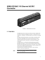
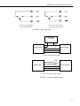
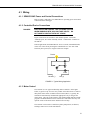
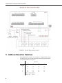
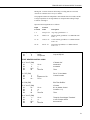
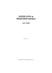
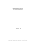
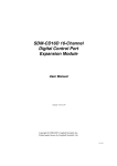
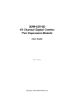
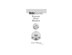
SDM-CD16AC 16 CHANNEL AC/DC CONTROLLER REVISION: 5/00 COPYRIGHT (c) 1987-2000 CAMPBELL SCIENTIFIC, INC. This is a blank page. Warranty and Assistance The SDM-CD16AC 16 CHANNEL AC/DC CONTROLLER is warranted by CAMPBELL SCIENTIFIC, INC. to be free from defects in materials and workmanship under normal use and service for twelve (12) months from date of shipment unless specified otherwise. Batteries have no warranty. CAMPBELL SCIENTIFIC, INC.'s obligation under this warranty is limited to repairing or replacing (at CAMPBELL SCIENTIFIC, INC.'s option) defective products. The customer shall assume all costs of removing, reinstalling, and shipping defective products to CAMPBELL SCIENTIFIC, INC. CAMPBELL SCIENTIFIC, INC. will return such products by surface carrier prepaid. This warranty shall not apply to any CAMPBELL SCIENTIFIC, INC. products which have been subjected to modification, misuse, neglect, accidents of nature, or shipping damage. This warranty is in lieu of all other warranties, expressed or implied, including warranties of merchantability or fitness for a particular purpose. CAMPBELL SCIENTIFIC, INC. is not liable for special, indirect, incidental, or consequential damages. Products may not be returned without prior authorization. To obtain a Returned Materials Authorization (RMA), contact CAMPBELL SCIENTIFIC, INC., phone (435) 753-2342. After an applications engineer determines the nature of the problem, an RMA number will be issued. Please write this number clearly on the outside of the shipping container. CAMPBELL SCIENTIFIC's shipping address is: CAMPBELL SCIENTIFIC, INC. RMA#_____ 815 West 1800 North Logan, Utah 84321-1784 CAMPBELL SCIENTIFIC, INC. does not accept collect calls. Non-warranty products returned for repair should be accompanied by a purchase order to cover the repair. 815 W. 1800 N. Logan, UT 84321-1784 USA Phone (435) 753-2342 FAX (435) 750-9540 www.campbellsci.com Campbell Scientific Canada Corp. 11564 -149th Street Edmonton, Alberta T5M 1W7 CANADA Phone (780) 454-2505 FAX (780) 454-2655 Campbell Scientific Ltd. Campbell Park Hathern Road Shepshed, Leics. LE12 9RP ENGLAND Phone (44)-50960-1141 FAX (44)-50960-1091 This is a blank page. SDM-CD16AC 16 Channel AC/DC Controller Table of Contents 1. Function...................................................................... 1 2. Control Specifications ............................................... 2 3. Power Considerations ............................................... 2 4. Installation .................................................................. 4 4.1 Wiring ...................................................................................................... 5 5. Address Selection Switches ..................................... 6 6. Datalogger Instruction 104 (21X, CR10) 29 (CR7) . 7 7. Theory of Operation................................................... 8 8. Program Example....................................................... 8 Figures 1. 2. 3. 4. 5. 6. SDM-CD16AC Face Panel ........................................................................ 1 Switch Operation........................................................................................ 3 Connection Block Diagrams ...................................................................... 3 Typical Wiring Application ....................................................................... 5 CD16AC Relay Outputs to MCCE ............................................................ 6 Addressing ................................................................................................. 7 Table 1. Datalogger to SDM-CD16AC Connections ............................................... 4 This is a blank page. AUTO OFF ON 1 C2 16 C2 16 C2 : S/N 16 C2 C2 C2 D GN 2V +1 16 C2 C2 C2 AU 16 F OF ON TO 5 16 1 16 C2 C2 14 C2 16 C2 13 C2 C2 12 C2 C2 C2 11 16 C2 C2 10 C2 16 C2 9 C2 C2 16 C2 8 C2 C2 7 16 C2 C2 C2 16 6 C2 C2 5 C2 C2 4 C2 C2 3 C2 16 C2 C2 2 C2 16 C2 C2 16 SDM-CD16AC 16 Channel AC/DC Controller C2 C1 C2 C2 C2 C3 C2 16 C2 C2 C NEL AC/D A S6 1 C D AN 1 2 3 0 16 IN DE MA A US CH T RN IPM D QU TE L E LISTRO N CO Z21 L 5 IA TR US IND 2 3 1 ADDRESSES h Uta n, ga Lo C ER HP 1/6 HP C R VD VAC /10 12 277 AC 1 NT : V CO UT 5 A 25 INP D: 5 A 1 A LO L OL 0 FIGURE 1. SDM-CD16AC Face Panel 1. Function The SDM-CD16AC has 16 AC/DC relay control ports and is compatible with CSI's CR10, 21X and CR7 dataloggers (see Figure 1). Each relay port can be controlled by a datalogger or controlled manually with a manual override toggle switch. The toggle switch has three positions; "ON" and "OFF" for manual override, and "AUTO" for datalogger control. In the "ON" position, the common (COM) and normally open (NO) contacts are closed (see Figure 2). In the "AUTO" position, the state of the relays are controlled by the datalogger control ports. The SDM-CD16AC is a synchronously addressed datalogger peripheral. Datalogger control ports 1, 2, and 3 are used to address the SDM-CD16AC, then clock out the desired state of each of the 16 control ports. Up to 16 SDMCD16ACs may be addressed, making it possible to control a maximum of 256 ports from the first three datalogger control ports. I/O Instruction 104 is used by the 21X and CR10 to control the SDMCD16AC. The CR7 uses Instruction 29. NOTE Ensure that the datalogger contains the appropriate instruction prior to system deployment. 1 SDM-CD16AC 16 Channel AC/DC Controller 2. Control Specifications Compatible dataloggers: CR10, 21X, CR7. Operating voltage: 12 VDC nominal (9 to 18). Current drain at 12 VDC: 6 mA quiescent; 45 mA per active LED (switch on or auto active). Total cable length: 20 ft (CR10, 21X), 600 ft (CR7) Toggle switch: ON/OFF manual override; AUTO for datalogger control. Underwriters Laboratories (UL) and Canadian Underwriters Laboratories (CUL) listed product. UL and CUL listing number is 5Z21. RELAY SPECIFICATIONS Arrangement: Single pole double throw, Break before make Contact material: Gold-clad silver Individual contact rating: 5 A at 30 VDC, .3 A at 110 VDC, 5 A 1/10 HP at 125 VAC, 5 A 1/6 HP at 277 VAC Coil voltage: 9 to 18 VDC Coil resistance: 360 Ohms•±10% Expected life (contact closures): Mechanical 107 Actuation/Release time: Approx. 4 ms Operating temp.: -40° to 70°C 3. Power Considerations The SDM-CD16AC power requirements are large compared to most CSI products. For most applications an external power supply (see Figure 3) is recommended to power the SDM-CD16AC. For some applications it may be convenient to use the datalogger supply to power the SDM-CD16AC (see Figure 3). For long-term applications, the lead acid power supply available with CSI dataloggers should be used, allowing the batteries to be float charged. It is not recommended that the datalogger alkaline supply be used to power the SDM-CD16AC for long term applications. If the datalogger lead acid supply is used, the number of SDM-CD16AC's that can be powered is limited by the 300 mA current sourcing capability of the wall charger. With a continuous 6 mA current drain per SDM-CD16AC and 45 mA per active LED, a maximum of 6 LEDs may be powered by the datalogger, after which, more current is drawn than can be sourced by the wall charger. If this condition is maintained, it will ultimately lead to battery deep discharge, requiring new batteries. 2 SDM-CD16AC 16 Channel AC/DC Controller Position of Contacts When Coil is Energized (ON) Position of Contacts When Coil Is Not Energized (OFF) FIGURE 2. Switch Operation EXTERNAL 9 TO 18 VDC + — GND 12 V SDM-CD16AC C1 DATALOGGER C2 C3 Connection With External Supply SDM-CD16AC GND 12 V C1 C2 C3 DATALOGGER Connection with Datalogger Supply FIGURE 3. Connection Block Diagrams 3 SDM-CD16AC 16 Channel AC/DC Controller TABLE 1. Datalogger to SDM-CD16AC Connections Connection Order First Second SDM-CD16AC 12 V Gnd C1 C2 C3 Datalogger 12 V on datalogger or external supply Gnd C1 (Control Port 1) C2 (Control Port 2) C3 (Control Port 3) Function Power Common ground Data Clock Enable If the 21X power supply is used to power the SDM-CD16AC, all low level analog measurements (thermocouples, pyranometers, thermopiles, etc.) must be made differentially. This is a result of slight ground potentials created along the 21X analog terminal strip when the 12 V supply is used to power peripherals. This limitation reduces the number of available analog input channels and may mandate an external supply for the SDM-CD16AC. 4. Installation CAUTION • The SDM-CD16AC must be installed in an enclosure that provides a pollution degree 2 environment (normally, only nonconductive pollution. However, a temporary conductivity caused by condensation may be expected). All Campbell Scientific enclosures meet this requirement. • Use copper conductors only. • Wire Range: 30 − 14 AWG • Tightening Torque: 5 − 7 in./lb. • Use minimum 60/75 degree C wire. • Input power must be connected to a class 2 supply only. All Campbell Scientific power supplies meet the class 2 supply requirements. The order in which connections are made is critical. Always connect 12 V first, followed by ground, then Control Ports. For datalogger connections, see Table 1. Multiple SDM-CD16AC's may be wired in parallel by connecting the datalogger side of one SDM-CD16AC to the next. For CR10 and 21X dataloggers, the total length of the cables connecting the SDM-CD16AC's should not exceed 20 feet. Total cable lengths in excess of 20 feet will adversely influence communication performance. For CR7 dataloggers, the total cable length should not exceed 600 feet. 4 SDM-CD16AC 16 Channel AC/DC Controller 4.1 Wiring 4.1.1 SDM-CD16AC Power and Control Connections Refer to Figure 3 and Table 1 for SDM-CD16AC operating power and control connections to the datalogger. 4.1.2 Controlled Device Connections DANGER! ELECTROCUTION HAZARD! USE EXTREME CAUTION WHEN WORKING WITH HIGH VOLTAGE INPUTS. DO NOT COME IN CONTACT WITH HOT LEADS! Figure 2 shows how the switches in each channel operate. NO means “normally open”, NC means “normally closed”. COM means “common” to NO and NC. In most applications, the SDM-CD16AC acts as a switch (controllable break) in one wire of the circuit powering the controlled device. One side of this break may have power (hot). Figure 4 shows an example. Device NO NC COM Neutral (-) Hot (+) FIGURE 4. Typical Wiring Application 4.1.3 Motor Control The CD16AC is a UL approved Start/Stop motor controller. In the figure below, a typical 5 Amp 115 VAC relay contact circuit shows how to control a three phase motor starter in a Motor Control Center (MCC). Typically, the CR10X will automatically command the appropriate relay to energize the motor starter. The relay in the CD16AC will remain latched until the CR10X program commands that the motor be turned off, at which time the relay will open the circuit to the motor starter and the motor will stop. The CD16AC can be used to control three phase pump motors, air blowers, and large control valves in the same fashion. 5 SDM-CD16AC 16 Channel AC/DC Controller FIGURE 5. CD16AC Relay Outputs to MCC 5. Address Selection Switches Each SDM-CD16AC can have 1 of 16 addresses. Shipped from the factory, the address is set at 00. The following table shows switch position and the corresponding address (see Figure 6). Switch A 0 1 2 3 0 00 01 02 03 1 10 11 12 13 2 20 21 22 23 32 33 Switch B 3 6 30 31 Base 4 Address Matrix (00, 01, 02 . . . 32, 33) SDM-CD16AC 16 Channel AC/DC Controller 1 A 2 3 0 B 1 AD S E R D 2 3 0 FIGURE 6. Addressing 6. Datalogger Instruction—104 (21X, CR10) 29 (CR7) Instruction 104 is used by the 21X and CR10 to control the SDM-CD16AC, and Instruction 29 is used by the CR7. The Instruction description is given below. SDM-CD16AC outputs that are to be controlled by the datalogger must have the toggle switch in the AUTO position. Instruction 104 SDM-CD16AC use with CR10 and 21X Param. 1 2 3 Type 2 2 4 Description Reps (# of modules sequentially addressed) Starting Address (base 4: 00..33) Starting Input Location Execution Time = 2 ms per Rep for the CR10, 3.5 ms per Rep for the 21X Instruction 29 - SDM-CD16AC use with CR7 Param 1 2 3 4 5 Type 2 2 2 2 4 Description Reps (# of modules sequentially addressed) Device (2 = SDM-CD16AC) Starting Address (base 4: 00..33) Card (Excitation card #) Starting Input Location Execution Time = 150 to 190 ms per Rep The number of SDM-CD16ACs to be addressed is defined by the Reps (repetitions) parameter. Each Rep will sequentially address (00, 01, 02,...32, 33) SDM-CD16ACs starting with the address specified in parameter 2 (Instruction 29 parameter 3). 7 SDM-CD16AC 16 Channel AC/DC Controller For each Rep, the 16 ports of the addressed SDM-CD16AC are set according to 16 sequential Input Locations starting at the Input Location specified in parameter 3 (Instruction 29 parameter 5). Any non-zero value stored in an input location activates the associated SDM-CD16AC port. A value of zero (0) deactivates the port For example, assuming 2 Reps and a starting Input Location of 33, OUTPUT 1 through 16 of the first SDM-CD16AC are set according to Input Locations 33 through 48, and OUTPUT 1 through 16 of the second SDM-CD16AC are set according to Input Locations 49 through 64. For Instruction 29, the Device (parameter 2) specifies what type of synchronously addressed peripheral is to be addressed. The Device code for an SDM-CD16AC is 2. For Instruction 29 only (CR7), the Card parameter 4 specifies which 725 Excitation Card is being used for the Control Port signals. The Reps parameter does not advance beyond the specified Card, requiring another Instruction 29 for each 725 Excitation Card used. 7. Theory of Operation The SDM-CD16AC is a synchronously addressed peripheral. C2 and C3, driven high by the datalogger, initiate a cycle. While holding C3 high, the datalogger drives C2 as a clock line and C1 as a serial data line. The datalogger shifts out a data bit on C1 (LSB first) on the falling edge of the C2 clock. The SDM-CD16AC shifts in the C1 data bit on the rising edge of the C2 clock. The first 8 bits clocked out represent the SDM-CD16AC address. If the address matches the SDM-CD16AC's address, the SDM-CD16AC is enabled. If enabled, the next 16 bits are shifted into the SDM-CD16AC, each bit controlling one port, the first of which controls OUTPUT1. When the 16 control bits are clocked in, C2 is held high while C3 is pulsed low then high to latch the control bits. The datalogger then lowers both C3 and C2 to complete the cycle. 8. Program Example The example is written for the CR10 Measurement and Control Module. The program concepts presented are the same for the 21X and CR7 dataloggers with minor program code changes. In this example, the SDM-CD16AC is used to control the temperature between 23° and 28°C in each of 5 greenhouses. In each green house the SDMCD16AC controls a heating unit, a refrigerating unit, and an air mixing fan according to the following conditions. Heating unit: Activate when temperature < 23.5°C. Deactivate when temperature > 25.5°C Cooling unit: Activate when temperature > 27.5°C. Deactivate when temperature < 24.5°C 8 SDM-CD16AC 16 Channel AC/DC Controller Mixing fan: Activate whenever the heating or cooling units are activated. Activate for 5 minutes out of every 15 minutes. The program assumes the temperature measurements have been made, and the average temperature for each greenhouse is computed and residing in Input Locations 1 through 5. Input Location assignments are as follows: Input Location Location Label Description 1..5 Temp #1..#5 Avg temp, greenhouse 1..5 10..14 Heat #1..#5 Heater control, greenhouse 1..5 SDM-CD16AC Port 1..5 15..19 Cool #1..#5 Cooler control, greenhouse 1..5 SDM-CD16AC Port 6..10 20..24 Fan #1..#5 Fan control, greenhouse 1..5 SDM-CD16AC Port 11..15 01: Beginning of Loop (P87) 01: 0 Delay 02: 5 Loop Count Master Loop, End Loop at Step 30 START HEATER CONTROL LOGIC 02: If X<=>F (P89) 01: 1-02: 4 03: 23.5 04: 30 X Loc < F Then Do 03: Z=F (P30) 01: 1 02: 0 03: 10-- F Exponent of 10 Z Loc : 04: End (P95) If "Heater On" threshold is exceeded Then Put a "1" into Heater Control Location End Then Do/End 05: If X<=>F (P89) 01: 10-02: 2 03: 0 04: 30 X Loc <> F Then Do 06: If X<=>F (P89) 01: 1-02: 3 03: 25.5 04: 30 X Loc >= F Then Do If Heater #1 on (Heater Control Location <> 0) Then Temp #1 Check Upper Threshold to see if heater should be turned off 9 SDM-CD16AC 16 Channel AC/DC Controller 07: Z=F (P30) 01: 0 02: 0 03: 10-- F Exponent of 10 Z Loc : If heater should be turned off, enter a "0" into heater control location 08: End (P95) Else Then Do/End 09: Else (P94) Else, If the heater is off, 10: Z=F (P30) 01: 0 02: 0 03: 10-- F Exponent of 10 Z Loc : 11: End (P95) Enter a "0" into heater control location End Then Do/Else/End END HEATER CONTROL LOGIC START COOLER CONTROL LOGIC 12: If X<=>F (P89) 01: 1-02: 3 03: 27.5 04: 30 X Loc >= F Then Do 13: Z=F (P30) 01: 1 02: 0 03: 15-- F Exponent of 10 Z Loc : 14: End (P95) 10 If "Cooler" on threshold is exceeded Then Put a "1" into cooler Control Location End Then Do/End 15: If X<=>F (P89) 01: 15-02: 2 03: 0 04: 30 X Loc <> F Then Do 16: If X<=>F (P89) 01: 1-02: 4 03: 24.5 04: 30 X Loc < F Then Do 17: Z=F (P30) 01: 0 02: 0 03: 15-- F Exponent of 10 Z Loc : If cooler is on (Cooler control Location <>0) Then Check lower threshold to see if cooler should be turned off If cooler should be turned off, put a "0" into cooler control location 18: End (P95) End Then Do/End 19: Else (P94) Else if cooler is off SDM-CD16AC 16 Channel AC/DC Controller 20: Z=F (P30) 01: 0 02: 0 03: 15-- F Exponent of 10 Z Loc : 21: End (P95) Put a "0" into cooler control location End Then Do/Else/End END COOLER CONTROL LOGIC START FAN CONTROL LOGIC BASED ON HEATER/COOLER 22: If X<=>F (P89) 01: 10-02: 2 03: 0 04: 11 X Loc <> F Set high Flag 1 If heater is on 23: If X<=>F (P89) 01: 15-02: 2 03: 0 04: 11 X Loc <> F Set high Flag 1 24: If Flag/Port (P91) 01: 11 02: 30 Do if flag 1 is high Then Do 25: Z=F (P30) 01: 1 02: 0 03: 20-- F Exponent of 10 Z Loc: If cooler is on Then Put a "1" into fan control location Else, If flag 1 is reset F Exponent of 10 Z Loc : 28: End (P95) 29: Do (P86) 01: 21 Set flag 1 If flag 1 is set 26: Else (P94) 27: Z=F (P30) 01: 0 02: 0 03: 20-- Set flag 1 Put a "0" into fan control location End Then Do/Else/End Reset flag 1 Set low Flag 1 30: End Loop (P95) End Master Loop END FAN CONTROL LOGIC BASED ON HEATER/COOLER START FAN CONTROL LOGIC BASED ON TIME 31: If time is (P92) 01: 10 02: 15 03: 12 minutes into a minute interval Set high Flag 2 If 5 minutes remain out of 15 minute interval, set flag 2 11 SDM-CD16AC 16 Channel AC/DC Controller 32: If Flag/Port (P91) 01: 12 02: 30 If flag 2 is set Do if flag 2 is high Then Do Then 33: Beginning of Loop (P87) 01: 0 Delay 02: 5 Loop Count Start fan loop 34: Z=F (P30) 01: 1 02: 0 03: 20-- PUT A "1" INTO FAN CONTROL LOCATION F Exponent of 10 Z Loc : 35: End (P95) End fan loop 36: End (P95) End then do 37: If time is (P92) 01: 0 02: 15 03: 22 minutes into a minute interval Set low Flag 2 Reset flag 2 at the end of the 15 minute END FAN CONTROL LOGIC BASED ON TIME INPUT LOCATIONS 10 THROUGH 24 ARE NOW LOADED WITH "1" OR "0" TO SET PORTS ON THE SDM-CD16AC. 38: SDM-CD16AC (P104) 01: 1 Reps 02: 00 Address 03: 10 Loc 39: End Table 1 (P) 12 Send instructions to the SDM-CD16AC with address 00