1
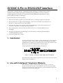
SC932C 9-Pin to RS232-DCE Interface User Guide Issued 27.2.97 Copyright 1997 Campbell Scientific Ltd. Guarantee This equipment is guaranteed against defects in materials, workmanship, and software. This guarantee applies for twelve months from date of delivery. We will repair or replace products which prove to be defective during the guarantee period provided they are returned to us prepaid. The guarantee will not apply to: • Equipment which has been modified or altered in any way without the written permission of Campbell Scientific • Batteries • Any product which has been subjected to misuse, neglect, acts of God or damage in transit. Campbell Scientific will return guaranteed equipment by surface carrier prepaid. Campbell Scientific will not reimburse the claimant for costs incurred in removing and/or reinstalling equipment. This guarantee and the Company’s obligation thereunder is in lieu of all other guarantees, expressed or implied, including those of suitability and fitness for a particular purpose. Campbell Scientific is not liable for consequential damage. Please inform us before returning equipment and obtain a Repair Reference Number whether the repair is under guarantee or not. Please state the faults as clearly as possible, and if the product is out of the guarantee period it should be accompanied by a purchase order. Quotations for repairs can be given on request. When returning equipment, the Repair Reference Number must be clearly marked on the outside of the package. Note that goods sent air freight are subject to Customs clearance fees which Campbell Scientific will charge to customers. In many cases, these charges are greater than the cost of the repair. Campbell Scientific Ltd, Campbell Park, 80 Hathern Road, Shepshed, Leicestershire, LE12 9RP, UK Tel: +44 (0) 1509 601141 Fax: +44 (0) 1509 601091 Email: [email protected] www.campbellsci.co.uk Contents 1. Installation........................................................................ 1 2. Use with Intelligent Telephone Modems ........................ 1 3. Other Applications........................................................... 2 Appendix A. SC932C to RS232 Device Connection Details ..................................................................A-1 A.1 Cable for Connection to a 25-way DCE Interface ....................................... A-1 A.2 Cable for Connection to a 9-way DCE Interface ......................................... A-1 Appendix B. Technical Details of Special Modes of Operation .............................................................B-1 B.1 B.2 B.3 B.4 Power Modes................................................................................................ B-1 Handshaking Lines ....................................................................................... B-2 ‘Printer Only’ Output ................................................................................... B-2 Maximum Recall Interval............................................................................. B-2 Appendix C. Specifications...............................................C-1 Figures 1. SC932C Connected to RAD-SRM Short Haul Modem ...................................... 1 A-1 Minimum Connections for SC932C to 25-way DCE Interface ................... A-1 A-2 Minimum Connections for SC932 to 9-way DCE Interface ........................ A-1 B-1 Connections for Using SC932C in ‘Printer’ Mode ...................................... B-2 Tables C-1 25-Pin Male Connector Pin-out ................................................................... C-2 C-2 9-Pin Male Connector Pin-out ..................................................................... C-2 SC932C 9-Pin to RS232-DCE Interface The SC932C is used to interface a Campbell Scientific datalogger to modem devices that are configured with an RS232 DCE (Data Communications Equipment) serial port. The most common application is to allow the connection of a RAD-SRM short haul modem or third party telephone modem to a datalogger. The SC932C has the following features: • Generates true RS232 signal levels to the DCE device, resulting in good noise immunity. • Powered from the 5V supply of the datalogger, which is also available to provide power to the DCE, if required for line-powered modems. • Generates the required ring signal to wake up the datalogger, either when characters are received or when there is a ring signal from the DCE. • Allows simultaneous connection of synchronous devices (e.g. Storage Modules) to the datalogger. • Provides a mechanism for the datalogger to control the line state of intelligent modems via DTR handshaking control. • Convenient ‘jumperless’ design. 1. Installation Use the SC12 ribbon cable (provided) to connect the datalogger’s 9-pin serial port to the 9-pin connector on the SC932C. The SC932C can usually be connected to the RS232 device by plugging the SC932C directly into the serial connector on the RS232 device. No further configuration is normally required. A typical application with a RAD modem would comprise: SC932C Figure 1 SC932C Connected to RAD-SRM Short-Haul Modem If the RS232 device does not have a suitable 25-way ‘D’ socket, you may need an adaptor cable (see Appendix A). 2. Use with Intelligent Telephone Modems If an ‘intelligent’ telephone modem is being used, configure it to allow the SC932C to control its line status via the DTR line. This can prevent the modem staying on-line unnecessarily, which can lead to excessive telephone charges and also delay reconnection to the datalogger. 1 SC932C 9-Pin to RS232-DCE Interface Most phone modems can be configured to respond to the DTR line, although this is not always the default setting. Although this feature is sometimes controlled by a hardware configuration switch, more often it is a software setting, e.g. AT&D2&W is the command for a Hayes-compatible modem to force the modem to follow the DTR status. 3. Other Applications The SC932C can be used in more specialist applications. Appendix B gives installation details where even lower power consumption may be possible, and also for applications where higher power outputs for the RS232 device are required. 2 Appendix A. SC932C to RS232 Device Connection Details This Appendix gives details of the cables required for connection of an SC932C to DCE type RS232 devices, if the SC932C cannot be directly plugged into the 25-way DCE, RS232 socket. A.1 Cable for Connection to a 25-way DCE Interface A standard pin-to-pin cable is suitable. However, if a custom cable is to be made it must make the following minimal connections: 25-Way D Pin No. 2 SC932C 25-Way D Pin No. 2 3 3 7 7 20 20 4* 4* 1 DCE Device Cable Shield Figure A-1 Minimum Connections for SC932C to 25-way DCE Interface NOTE The link between pins 4 and 4 marked with the * may not be required — see the section on low power operation in Appendix B. A.2 Cable for Connection to a 9-way DCE Interface Some newer modem-type devices are fitted with 9-way D connectors designed to plug directly into 9-way serial ports as found on most ‘AT’ style PCs. Commercial adaptor cables are available. If you use a custom made cable, it should have the following connections: 25-Way D Pin No. 2 SC932C 9-Way D Pin No. 3 3 2 7 5 DCE Device 20 4 4* 7* 1 Cable Shield Figure A-2 Minimum Connections for SC932C to 9-way DCE Interface NOTE The link between pins 4 and 7 marked with the * may not be required — see the section on low power operation in Appendix B. A-1 Appendix B. Technical Details of Special Modes of Operation The SC932C is designed as a simple plug-in device with no internal jumpers. This Appendix describes alternative modes of operation and also relates these to Campbell Scientific’s original SC932 interface, for those users who are already familiar with that interface. B.1 Power Modes B.1.1 Normal Mode In the normal mode of operation for the SC932C, a continuous supply of 4.3V is available from the RTS line; this can be used as a source of power by some interfaces, e.g. the RAD modem. The RTS and DTR lines both switch to >7V when the SC932C becomes active. This mode will work for the majority of applications. This mode is similar to the medium power setting of the SC932. B.1.2 High Power Mode A ‘high power’ setting can be forced, where RTS and DTR are held permanently at >7V, by connecting pin 11 of the 25-way D connector to a voltage >3.5V DC. To do this, add a link between pins 11 and 4 (RTS) on the SC932C’s 25-way D connector. In this mode the SC932C consumes approximately 10-15mA continuously. This mode is normally only necessary for devices which require fully active input lines to provide a source of power to allow them to receive data and transmit it to the SC932C. NOTE In this mode the SC932C will not block the transmission of synchronous data (e.g. Storage Module data) to the RS232 device. This could cause a problem if, for example, the RS232 device is reconfigured by the stream of binary data. Synchronous data is not normally transmitted through the SC932C when in its normal mode of operation. B.1.3 Low Power Mode The lowest power consumption can be achieved with RS232 devices which do not need to source power from the SC932C. This is done by not connecting pin 11 or the RTS line to the RS232 device. This is because a small current will flow from the active RTS line into a standard RS232 RTS input on the device (normally <1.5mA), even when the SC932C is inactive. Leaving RTS disconnected will only work if the RS232 device does not require an active RTS line during communication. Many high speed modems do have this requirement, by default, but RTS/CTS handshaking can usually be turned off by software reconfiguration (please refer to the modem manual). B-1 SC932C 9-Pin to RS232-DCE Interface B.2 Handshaking Lines In its normal power mode, and when inactive (i.e. the datalogger ME line is low) the SC932C only holds the RTS line high to provide a source of power to linepowered modems, such as the RAD modem. The DTR line is controlled by the ME line of the datalogger. When ME is high the DTR line is powered high (>7V), but when the ME line returns to a low state, the DTR line enters a high impedance state; as far as the RS232 device is concerned, this has the same effect as the DTR line going low. This transition can be used to force the device to go off-line, if the device supports this. This feature is useful for some telephone modems as it allows the datalogger to force the modem off-line. The older SC932 only supports this type of handshaking when operated in its low power mode. NOTE The SC932C can be modified to support a form of RTS handshaking for the support of some specialised half-duplex interfaces. Please contact Campbell Scientific for further details. B.3 ‘Printer Only’ Output The SC932C can be used as a printer (PE/SDE enabled) device. However, unlike the SC932 where this mode can be set using internal jumpers, the SC932C requires a special connection in place of the normal direct SC12 cable. The connection to the SC932C should be made up as follows: Datalogger Pin No. SC932C 9-Way D Pin No. 1 1 2 2 4 No connection to SC932C 5 No connection to SC932C 6 5 9 9 Figure B-1 Connections for Using SC932C in ‘Printer’ Mode (Other wires can be left connected or disconnected.) With this connection the SC932C can be connected in parallel to another Campbell Scientific modem-type device. However, as with the SC932, any data output to synchronous devices (e.g. a Storage Module) will also be transmitted out through the RS232 connection. B.4 Maximum Recall Interval From the time that the datalogger leaves communications mode (ME goes low), there is a delay of approximately one second before serial or ring line activity from B-2 Appendix B. Technical Details of Special Modes of Operation the RS232 device will re-awaken the datalogger. This prevents spurious messages from the RS232 device (such as ‘loss of carrier’ messages from a modem) waking up the datalogger. The only consequence of this delay is that specialist software which polls dataloggers at frequent intervals will not be able to wake the same datalogger again during the delay period. Campbell Scientific are aware of some modems which will re-trigger the ring line, despite this delay. The only consequence of this is that the datalogger will remain in communications mode for an extra 30 seconds after the end of the call; this will waste a small amount of power and delay any output to a Storage Module. B-3 Appendix C. Specifications Data rates: up to 38,400 baud (limited by datalogger) Size: 63 x 55 x 17mm (L x W x D), excluding mating D connectors Operating environment: -25°C to +50°C, 0-95% RH (non-condensing) Connector pin assignments: see Tables C-1 and C-2 Power requirements: sources power from datalogger 5V supply via 9-way interface. Typical current consumption • <100µA with no RS232 load and pin 11 not connected • 2.2mA with RAD-SRM and no communication • 9.3mA with RAD-SRM, datalogger in communications mode, but low communications activity • 10.2mA with RAD-SRM, high communications activity Current consumption when driving other RS232 modems will vary with the number of lines connected and the input impedance of the inputs. With 3 inputs connected (DTR, RTS and Tx from the SC932C), of the minimum 3kΩ input impedance, and high communications activity the consumption may be up to 16mA. RS232 output levels • RTS 4.2 - 4.5V with 3kΩ load – quiescent state (ME low) • RTS full power 7 - 9V with 3kΩ load (ME high) • DTR 7.5 - 9.5V with 3kΩ load (8.8V typical with RAD-SRM); short circuit current 30mA typical • Tx greater than ±5V with 3kΩ load RS232 input thresholds Rx and RI • Input low 0.8V minimum • Input high 2.4V maximum • Input resistance 5KΩ Pin 11, power control input thresholds • Input low 1.3V maximum (normal power mode) • Input high 3.5V maximum (to enable high power mode) • Input resistance greater than 10kΩ • Maximum input voltage 20V Time-outs • Minimum RING IN pulse width to generate a ring signal to the datalogger is 20µs • Minimum delay between ME going low and RING IN enable is 0.5s (1s typical) C-1 SC932C 9-Pin to RS232-DCE Interface EMC Specification • Emissions BSEN 55022-1: 1995 • Immunity BSEN 50082-1: 1992 Connection Details Table C-1 25-Pin Male Connector Pin-out Pin No. 1 2 3 4 7 11 I/O out in out in Name GND TXD RXD RTS GND PWR 20 out DTR Description Chassis Ground SC932C transmits data on this line SC932C receives data on this line Held active by SC932C Signal Ground If held >3.5V will force SC932C into high power mode Held high if ME is high (see Appendix B) Table C-2 9-Pin Male Connector Pin-out Pin No. 1 2 3 4 5 6 9 C-2 I/O in out out in in in Name +5V GND RING RXD ME SDE TXD Description Regulated 5V supply Ground Ring signal to datalogger SC932C transmits on this line Modem Enable Synchronous Device Enable/Print Enable SC932C receives on this line