1
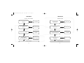
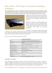
Dac manual:Cursa manual.qxd
29/11/2010
17:12
Page 1
CONTENTS
INTRODUCTION
1
TECHNOLOGY
2
FRONT PANEL INDICATORS & CONTROLS
3
BACK PANEL
4
IN USE & DIGITAL OUTPUT
5
FILTER SETTINGS
6
CONNECTIVITY
7
USB CONNECTIVITY
8
96kHz-192kHz OPERATION
9
TECHNICAL SPECIFICATIONS
10
TROUBLESHOOTING
11
TROUBLESHOOTING
12
GLOSSARY OF TERMS
13
Dac manual:Cursa manual.qxd
29/11/2010
17:12
Page 3
INTRODUCTION
TECHNOLOGY
The Rega DAC is a 16/20/24-bit at 32kHz to 192kHz digital to analogue
converter incorporating an enhanced version of the Rega designed circuit.
The input stage comprises a Wolfson digital receiver with a high stability low
jitter clock driving the receiver PLL. The receiver and PLL have their own
dedicated power supplies. The DAC stage comprises of a pair of parallelconnected Wolfson WM8742 DAC’s, which are driven via a buffer stage, which
ensures the integrity of the data being fed to the DAC IC’s – similar to the
arrangement used in the Isis (Rega’s reference CD player).
Developed to be simple to set up and use, the Rega DAC is designed to optimise
performance from any two channel PCM digital audio source.
With the PC (although a somewhat contentious issue in hi-fi circles) now widely
accepted as a creditable medium for storing and streaming music. The use of
high quality lossless files such as WAV, FLAC and ALAC offer performance
through the DAC equal to and in some cases better than red book CD. Great
care has been taken to remove noise generated by the PC and other input
sources. During development this was identified as a major drawback with
many DAC’s on the market today.
The output amplifier employs a discrete differential multiple feedback filter and
output amplifier, with a high cut-off frequency for use with higher sample rates.
We decided not to use a sample rate converter and process the data at the
incoming sample rate which keeps the signal processing to a minimum. Jitter
was minimised by synchronously clocking the digital data with our receiver PLL
(removing any jitter from the input signal).
The Rega DAC has been designed and engineered to achieve the highest
performance in its class. We hope you enjoy this Rega product for many years
to come.
All the capacitors associated with the analogue signal path are Nichicon FG
bypassed with MMK polyester capacitors, and low impedance conductive
polymer capacitors are used for DAC decoupling. The power supply utilizes a
toroidal transformer, fast rectifier diodes and again Nichicon FG capacitors.
There is a power supply for the control microcontroller, separate from the
digital & analogue audio stages. Special attention being paid to the inter IC
control signals ensuring the control data noise is kept to a minimum.
1
2
The Rega DAC housed in a custom aluminium and steel case boasts a pair of
Wolfson DAC IC’s and 5 user selectable digital filters, two isolated Co-axial
inputs, two Toslink SPDIF inputs and an isolated USB input.
Dac manual:Cursa manual.qxd
29/11/2010
17:12
Page 5
FRONT PANEL INDICATORS AND CONTROLS
BACK PANEL
Power on/off (button above Rega logo) When the power button is pressed
the Rega logo illuminates to indicate power is on.
Digital Inputs
Input Locked indicator This indicates the digital input signal is valid and the
PLL in the receiver is locked. When the Input Locked LED is off the soft mute is
activated.
Input This button selects the 5 available digital inputs. Push to advance to the
next input as follows:
USB
Optical 1
Optical 2
Co-axial 3
Co-axial 4
Sample rate LED’s (only valid when Input Locked is on)
32K – Indicates the incoming sample rate is 32kHz
44.1/48K – Indicates the incoming sample rate is 44.1 or 48kHz
88.2/96K – Indicates the incoming sample rate is 88.2 or 96kHz
192K – Indicates the incoming sample rate is 176.4 or 192kHz
3
USB - type B connector/Isolated
Optical Digital Input 1 - Optical/Toslink
Optical Digital Input 2 - Optical /Toslink
Co-Ax Digital Input 3 - Isolated 75Ω Co-axial Phono
Co-Ax Digital Input 4 - Isolated 75Ω Co-axial Phono
Digital output (via receiver & PLL) -SPDIF
Optical Toslink
Co-axial/Phono Isolated 75Ω
Analogue Output Left and Right Phono
Power Mains/line input IEC C5 type
Fuse Fuse holder
4
Dac manual:Cursa manual.qxd
29/11/2010
17:12
Page 7
IN USE
FILTER SETTINGS
Power-up the DAC using the power switch on the front panel. After a few
seconds you will hear an audible click from the output mute relay and the
analogue audio will be active. Please note: The front panel will display the
previously selected setting’s displayed before the unit was last powered down.
The cut-off points of the filters are in the upper end of the frequency range.
However, due to complex technical phenomena, this will have an effect lower in
the frequency band. For further description see the glossary of terms. These
settings are a matter of personal taste and may only offer subtle changes. We
suggest using Filter setting 1 and trying different settings with various
equipment.
If the currently selected input has an active source connected the Input Locked
LED along with the appropriate incoming sample rate LED will illuminate. Unless
the Input Locked LED is lit the sample rate indication is irrelevant. By pressing
the input selection switch you can select any one of the inputs. When the Input
Locked LED is off, or there is a transmission error the internal soft mute is
activated automatically.
By pressing the Filter selection switch you can select any one of the 5 available
digital filters 1,2,3,4 or 5. (The exact properties of these filters are outlined on
the opposite page).
Filter setting switch & LED’s Push to advance to the next filter.
Filter settings 1 – 5
(low sample rates 32/44.1/48K)
1 Linear phase half-band filter
2 Minimum phase soft-knee filter
3 Minimum phase half-band filter
4 Linear phase apodising filter
5 Minimum phase apodising filter
DIGITAL OUTPUT
The digital output mirrors the selected input. For example when input 2 has
been selected the digital output will be the signal present on input 2 but cleaned
up and re-clocked, this can be used to drive an auxiliary piece of equipment if
so desired.
Filter settings 1 – 5
(medium & high sample rates 88.2/96 & 176.4/192K)
1 Linear phase soft-knee filter
2 Minimum phase soft-knee filter
3 Linear phase brickwall filter
4 Minimum phase apodising filter
5 Linear phase apodising filter
5
6
Dac manual:Cursa manual.qxd
29/11/2010
17:12
Page 9
CONNECTIVITY (examples)
1 USB A-B/ 2 OPTICAL/3 CO-AXIAL
This page offers ‘suggested connectivity’, with so many products offering a
number of options it is important to check the manual of the product your are
connecting, for the appropriate or optimum output connection and settings
required to operate properly.
USB CONNECTIVITY
Connect a USB A-B type lead (as illustrated) from the DAC USB to a USB output
on your PC. The standard Windows ‘found new hardware’ dialogue will be
displayed on your PC in the bottom right hand corner of the screen.
USB A-B lead (not supplied)
The DAC will be recognised as ‘USB AUDIO DAC’. Installation should be
automatic as no driver disc is required. After a short period ‘your new
hardware is installed and ready to use’ should appear to confirm that
connection and installation has been successful.
It is recommended to switch off any other system sounds emitted by the PC via
the control panel. The DAC will automatically become the default for your PC
whilst connected. Once disconnected the previous default will be restored. If
this does not happen you can manually reset as follows :
Note: This unit only accepts two-channel PCM digital audio. You cannot connect
a Dolby Digital 5.1/7.1 or a DTS signal as they will not be recognised. If you wish
to connect a DVD or similar device, please ensure that the sound output of your
player is set to two-channel PCM.
7
Windows XP - Control panel/Sounds and audio devices/Audio/Sound Playback
Windows Vista/Windows 7 - Control Panel/Hardware and Sound/Manage Audio
Devices/select ‘USB AUDIO DAC’ from list.
Mac OS - System Preferences/Sound Output/Select Audio USB DAC.
8
Dac manual:Cursa manual.qxd
29/11/2010
17:12
Page 11
96kHz & 192kHz OPERATION
The Rega DAC can operate at 192kHz when used with a capable soundcard
connected via the Co-axial or optical input. Due to the limitations of some
operating systems the exact configuration and set-up can vary from one
PC/Laptop to another.
If you are constructing a high sample rate music server, we recommend that
the frequency response and THD of the final unit complete with the DAC,
soundcard and player is checked using high frequency test tones with suitable
measuring equipment to ascertain the playback chain is capable of true 96 &
192K operation.
This test will require specialist test tones and equipment. Loudspeakers should
not be used as certain frequencies could potentially damage the drive units.
Please note: Some PC/Laptop or disc players are only capable of a maximum
sample rate of 48kHz. The USB will only work at 32/44.1/48kHz 16-bit even if
you have a 96kHz & 192kHz playback configuration.
TECHNICAL SPECIFICATIONS
DAC Wolfson WM8742
Frequency Response (100KΩ load)
Low data rate 44.1/48KHz Filter 2 = 10Hz -0.05dB to 20KHz -0.1dB
Medium data rate 88.2/96KHz Filter 2 = 10Hz -0.05dB to 30KHz -1dB
High data rate 176.4/192KHz Filter 2 = 10Hz -0.05dB to 41KHz -1dB
Total Harmonic Distortion (24bit 96KHz) = 0.006% @ 1KHz
Signal To Noise Ratio -105dB
(relative to maximum output level with a 100Hz to 22KHz bandwidth)
Maximum output level = 2.175V into 100KΩ load
Bit resolution 16 to 24bit (USB is limited to 16bit)
Supported data rates = 32, 44.1, 48, 88.2, 96, 176.4, 192KHz
Digital inputs
USB Isolated (16bit 32/44.1/48KHz)
Input 1 Optical/Toslink (24bit 32/44.1/48/88.2/96/176.4/192KHz)
Input 2 Optical /Toslink (24bit 32/44.1/48/88.2/96/176.4/192KHz)
Input 3 Isolated 75Ω Co-axial (24bit 32/44.1/48/88.2/96/176.4/192KHz)
Input 4 Isolated 75Ω Co-axial (24bit32/44.1/48/88.2/96/176.4/192KHz)
Digital output (via receiver & PLL) - SPDIF
Optical Toslink Isolated 75Ω
Co-axial/SPDIF
Power 230v/115v/7.6W
Dimensions in cm W 21.5 x D 27 x H 8
Weight 4.0 Kg
9
10
Dac manual:Cursa manual.qxd
29/11/2010
17:12
Page 13
TROUBLESHOOTING
TROUBLESHOOTING
No power - no LED’s illuminated
Power ON - No output
No
Is the mains supply connected and the socket
switched on?
Correct the fault
Yes
Correct the fault
Yes
No
Is the front panel on/off switch fully
depressed?
Correct the fault (contact
Rega dealer if faulty)
Yes
No
Are the matching inputs on the amplifier
correclty selected?
Correct the fault
Yes
Yes
Has the fuse in the mains plug blown?
Replace with the same
rated fuse
No
Is the correct input on the DAC selected and
the input locked LED illuminated?
No
Select correct input
on the DAC
Yes
No
In the mains socket live?
(plug in another appliance to check)
Yes
No
Are the output connections
connected correctly?
Contact your Rega dealer
11
Check household fuse or
contact an electrician
No
Check connected digital product is
working properly
Yes
Contact your Rega dealer
12
Check setup and settings
Dac manual:Cursa manual.qxd
29/11/2010
17:12
Page 15
GLOSSARY OF TERMS
PLL
Phase lock Loop
PCM
Pulse code modulation
SPDIF
Sony Philips digital interface protocol
SOFT MUTE
Software mute (not output mute)
SOFT KNEE FILTER
Filter with a large transition band which reduces dispersion and delay
HALF BAND
Filter where the transition region is centred at one quarter of the sampling rate
APODISING FILTER
Filter exhibiting a smooth roll off
BRICKWALL FILTER
Filter exhibiting a steep roll off
FLAC/ALAC
Lossless audio formats
OWNERS LOG
(1)
Owner.......................................................................................................................................................
Date...........................................................................................................................................................
Where Purchased.................................................................................................................................
(2)
Owner.......................................................................................................................................................
Date...........................................................................................................................................................
Where Purchased................................................................................................................................
(3)
Owner.......................................................................................................................................................
Date...........................................................................................................................................................
Where Purchased................................................................................................................................
(4)
Owner.......................................................................................................................................................
Date...........................................................................................................................................................
Where Purchased................................................................................................................................
(5)
Owner.......................................................................................................................................................
Date...........................................................................................................................................................
Where Purchased................................................................................................................................
DIGITAL FILTER
Device or process that removes unwanted features from a signal.
13
14