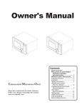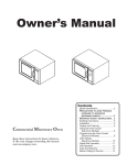
1
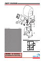
Installation Instructions and Safety Information
Vehicular Gate Operator
UL 325 and UL991 Listed
Class I, Class II, Class III and Class IV
Rev. A.1
March 2005
PARTS
PARTS DIAGRAM
DIAGRAM
18
6
4
2
9
3
13
20
8
13
19
10
3
21
11
24
5
22
23
Item
1
2
3
4
5
6
8
9
10
11
12
13
14
18
19
20
21
22
23
24
25
26
Description
Chassis
Electric Box
Limit Cam Spacer
24V 1/5HP DC Motor
Right-Angle Helical Bevel
Operator Cover
Limit Cam (2)
Limit switch (2)
Limit switch Holder
Sprocket Chain Drive
20' Chain & Bracket Set
Idler Pulley (2)
Warning signs and Sticker Set
Control Board
Toroid Transformer
Idler Bushing
Battery
Limit Switch Gear Box
Alarm
EMI Board
EMI Junction Box
EMI Junction Box Cover
Part No.
DSCH10
DUEB10
DSLCS10
DSMO10
DSGB10
DSCO10
DSLC10
DULS10
DSLH10
DSSK10
DSCB10
DSIP10
DSWS10
DUPCB10
DUTT10
DSIB10
DUBA10
DULG10
DUAL10
DUEMI10
DSEJB10
DSJBC10
1
Overall Dimensions
Center of
Drive Chain
19.50"
10.375"
19.50"
13.50"
Weight
WARNING - For Installation
By Qualified Personnel Only.
i
TECHNICAL SUPPORT 1 800 908 0884
70 lb.
TABLE
TABLE OF
OF CONTENTS
CONTENTS
Parts Diagram/Parts List . . . . . . . . . . . . . . . . . . . . . . . . . . . . . . . . . . . . . . . . .i
Important Safety Information
Important Safety Instructions . . . . . . . . . . . . . . . . . . . . . . . . . . . . . . . . . . . .2
Important Installation Instructions . . . . . . . . . . . . . . . . . . . . . . . . . . . . . . . .2-3
Maintenance/General Safety Precautions . . . . . . . . . . . . . . . . . . . . . . . . . . . .4
Terminology . . . . . . . . . . . . . . . . . . . . . . . . . . . . . . . . . . . . . . . . . . . . . . . .5
Photo Beam (non-contact sensor) Installation . . . . . . . . . . . . . . . . . . . . . . . . .6
Edge Sensor (contact sensor) Installation . . . . . . . . . . . . . . . . . . . . . . . . . . . .7
Manual Release . . . . . . . . . . . . . . . . . . . . . . . . . . . . . . . . . . . . . . . . . . . . . .7
Audible Alarm Reset Switch Installation . . . . . . . . . . . . . . . . . . . . . . . . . . . . .8
Warning Placard Installation . . . . . . . . . . . . . . . . . . . . . . . . . . . . . . . . . . . .8
Important Installation Information . . . . . . . . . . . . . . . . . . . . . . . . . . . . . . . .9
Specifications . . . . . . . . . . . . . . . . . . . . . . . . . . . . . . . . . . . . . . . . . . . . . . .9
Plans of Installation . . . . . . . . . . . . . . . . . . . . . . . . . . . . . . . . . . . . . . . . . . .10
Plan of Installation – Concrete Pads . . . . . . . . . . . . . . . . . . . . . . . . . . . . . . . .11
Gate Operator Installation
Step 1 through 3 – Operator Installation . . . . . . . . . . . . . . . . . . . . . . . . . . .12-13
Step 4 through 6 – Limit Switch Setup . . . . . . . . . . . . . . . . . . . . . . . . . . . . .14
Opening/Closing Setup . . . . . . . . . . . . . . . . . . . . . . . . . . . . . . . . . . . . . . . .15
Limit Switch Connections . . . . . . . . . . . . . . . . . . . . . . . . . . . . . . . . . . . . . .15
Electrical Installation
Electrical Installation (120/220 VAC) . . . . . . . . . . . . . . . . . . . . . . . . . . . . . . .17
Power Connections . . . . . . . . . . . . . . . . . . . . . . . . . . . . . . . . . . . . . . . . . . .18
Master/Slave Connections . . . . . . . . . . . . . . . . . . . . . . . . . . . . . . . . . . . . . .19
Vehicular Loop Detector Installation
Loop Layout Diagrams . . . . . . . . . . . . . . . . . . . . . . . . . . . . . . . . . . . . . . . .20
Installation Guidelines . . . . . . . . . . . . . . . . . . . . . . . . . . . . . . . . . . . . . . . .21
Accessory Connections
Open Commands; Safety Connections . . . . . . . . . . . . . . . . . . . . . . . . . . . . . .22
Radio Receiver . . . . . . . . . . . . . . . . . . . . . . . . . . . . . . . . . . . . . . . . . . . . . .23
Magnetic Lock; Solenoid; Guard Station . . . . . . . . . . . . . . . . . . . . . . . . . . . .24
Special Features
Intelligent Obstruction Sensor (Primary Entrapment Protection) . . . . . . . . . . . .25
Fail Safe/Fail Secure Operation; Hold Open Timer . . . . . . . . . . . . . . . . . . . . . .26
Gate Overlap Setting . . . . . . . . . . . . . . . . . . . . . . . . . . . . . . . . . . . . . . . . . .27
Troubleshooting . . . . . . . . . . . . . . . . . . . . . . . . . . . . . . . . . . . . . . . . . . . . .28-29
TECHNICAL SUPPORT 1 800 908 0884
1
IMPORTANT
IMPORTANT SAFETY
SAFETY INFORMATION
INFORMATION
WARNING - Not following these instructions may cause severe injury or death to persons.
IMPORTANT SAFETY INSTRUCTIONS
WARNING – To reduce the risk of severe injury or death:
1. READ AND FOLLOW ALL INSTRUCTIONS.
2. Never let children operate or play with gate controls. Keep the remote control away from children.
3. Always keep people and objects away from the gate. NO ONE SHOULD CROSS THE PATH OF
THE MOVING GATE.
4. Test the gate operator monthly. The gate MUST reverse on contact with a rigid object or when
an object activates the non-contact sensors. After adjusting the force or the limit of travel,
retest the gate operator. Failure to adjust and retest the gate operator properly can increase the
risk of injury or death.
5. Use the manual release only when the gate is not moving.
6. KEEP GATES PROPERLY MAINTAINED. Read the owner’s manual. Have a qualified service
person make repairs to gate hardware.
7. The entrance is for vehicles only. Pedestrians must use separate entrance.
8. Every gate operator installation MUST have secondary protection devices against entrapment,
such as edge sensors and photo beams more in particularly in places where the risk of
entrapment is more likely to occur.
9. SAVE THESE INSTRUCTIONS.
IMPORTANT INSTALLATION INSTRUCTIONS
1. Install the gate operator only when:
a) The operator is appropriate for the construction of the gate and the usage Class of the gate
(refer to page 5),
b) All openings of a horizontal slide gate are guarded or screened from the bottom of the gate
to a minimum of 4 feet (1.22 m) above the ground to prevent a 2-1/4 inch (57.2 mm)
diameter sphere from passing through the openings anywhere in the gate, and in that
portion of the adjacent fence that the gate covers in the open position,
c) ALL EXPOSED PINCH POINTS ARE ELIMINATED OR GUARDED, AND
d) GUARDING IS SUPPLIED FOR EXPOSED ROLLERS.
2. The operator is intended for installation only on gates used for vehicles. Pedestrians must be
supplied with a separate access opening.
3. The gate must be installed in a location so that enough clearance is supplied between the gate
and adjacent structures when opening and closing to reduce the risk of entrapment. Swinging
gates shall not open into public access areas.
4. The gate must be properly installed and work freely in both directions prior to the installation
of the gate operator. Do not over-tighten the operator clutch or pressure relief valve to
compensate for a damaged gate.
2
TECHNICAL SUPPORT 1 800 908 0884
IMPORTANT
IMPORTANT SAFETY
SAFETY INFORMATION
INFORMATION
WARNING - Not following these instructions may cause severe injury or death to persons.
IMPORTANT INSTALLATION INSTRUCTIONS Continued
5. The gate operator controls must be placed so that the user has full view of the gate area when
the gate is moving AND AWAY FROM THE GATE PATH PERIMETER,
6. Controls must be far enough from the gate so that the user is prevented from coming in contact
with the gate while operating the controls. Controls intended to be used to reset an operator
after 2 sequential activations of the entrapment protection device or devices must be located in
the line-of-sight of the gate. Outdoor or easily accessible controls shall have a security feature
to prevent unauthorized use.
7. All warning signs and placards must be installed where visible in the area of the gate. A minimum
of two placards shall be installed. A placard is to be installed in the area of each side of the
gate and be visible to persons located on the side of the gate on which the placard is installed.
8. For gate operators utilizing a non-contact sensor (Photo beam or like) in accordance with section
31.1.1 of the UL325 standard:
a) See instructions on the placement of non-contact sensors for each Type of application
(refer to page 6),
b) Care shall be exercised to reduce the risk of nuisance tripping, such as when a vehicle, trips
the sensor while the gate is still moving, and
c) One or more non-contact sensors shall be located where the risk of entrapment or obstruction exists, such as the perimeter reachable by a moving gate or barrier (refer to page 6).
9. For a gate operator utilizing a contact sensor (Edge sensor or like) in accordance with section
31.1.1 of the UL325 standard:
a) One or more contact sensors shall be located where the risk of entrapment or obstruction
exists, such as at the leading edge, trailing edge, and post mounted both inside and outside
of a vehicular horizontal slide gate (refer to page 7).
b) One or more contact sensors shall be located at the bottom edge of a vehicular vertical lift gate.
c) One or more contact sensors shall be located at the pinch point of a vehicular vertical pivot gate.
d) A hardwired contact sensor shall be located and its wiring arranged so that the communication
between the sensor and the gate operator is not subjected to mechanical damage.
e) A wireless contact sensor such as one that transmits radio frequency (RF) signals to the gate
operator for entrapment protection functions shall be located where the transmission of the
signals are not obstructed or impeded by building structures, natural landscaping or similar
obstruction. A wireless contact sensor shall function under the intended end-use conditions.
f) One or more contact sensors shall be located on the inside and outside leading edge of a
swing gate. Additionally, if the bottom edge of a swing gate is greater than 6 inches (152
mm) above the ground at any point in its arc of travel, one or more contact sensors shall be
located on the bottom edge (refer to page 7).
g) One or more contact sensors shall be located at the bottom edge of a vertical barrier (arm).
TECHNICAL SUPPORT 1 800 908 0884
3
IMPORTANT
IMPORTANT SAFETY
SAFETY INFORMATION
INFORMATION
WARNING - Not following these instructions may cause severe injury or death to persons.
MAINTENANCE
Remove the Power Harness from the Control Board (refer to page 17)
• Clean and lubricate the gate track wheels using the recommended lubricant.
• Inspect the track for any signs of cracking or separation.
• Check that all mounting hardware of the gate operator is properly tighten.
• Ensure that the gate moves freely.
• Check for corroded parts and replace if necessary.
• Check the battery for the following:
Battery connections must be free of corrosion.
Battery voltage must be 26 VDC (fully charged battery).
Reconnect the Power Harness for the Control Board (refer to page 17)
• Check and confirm the proper operation of all safety devices (photoelectric eye, edge sensors or like).
• Check and confirm the operation of all installed accessories.
• Check and confirm the operation of all special features such as the Intelligent Obstruction Sensor, Hold
Open Timer (refer to page 20 to 27)
• Check and confirm the operation of the manual release (refer to page 7)
• Verify battery backup functionally by turning off the power source (120 VAC and 220 VAC). DO NOT
FORGET TO TURN ON THE POWER SOURCE AFTER VERIFICATION.
GENERAL SAFETY PRECAUTIONS
The following precautions are an integral and essential part of the product and must be supplied to the user.
Read them carefully as they contain important indications for the safe installation, use and maintenance.
• These instruction must be kept and forwarded to all possible future users of the system.
• This product must be used only for that which it has been expressly designed.
• Any other use is to be considered improper and therefore dangerous.
• The manufacturer cannot be held responsible for possible damage caused by improper, erroneous or
unreasonable use.
• Avoid operating in the proximity of the hinges or moving mechanical parts.
• Do not enter the path of the moving gate while in motion.
• Do not obstruct the motion of the gate as this may cause a situation of danger.
• Do not allow children to play or stay within the the path of the moving gate.
• Keep remote control or any other control devices out of the reach of children, in order to avoid possible
involuntary activation of the gate operator.
• In case of break down or malfunctioning of the product, disconnect from the main power source. Do not
attempt to repair or intervene directly, contact only qualified personnel for repair.
• Failure to comply with the above may create a situation of danger.
• All cleaning, maintenance or repair work must be carried out by qualified personnel.
• In order to guarantee that the system works efficiently and correctly it is important to have the manufacturer’s
instructions on maintenance of the gate and operator carried out by qualified personnel.
• In particular, regular checks are recommended in order to verify that the safety devices are operating correctly.
All installation, maintenance and repair work must be documented and made available to the user.
Installer:
_____________________________________________________
____________
Signature
Date
Contact:
_________________________________________________________
_________________________________________________________
4
TECHNICAL SUPPORT 1 800 908 0884
TERMINOLOGY
TERMINOLOGY
UL325 Gate Operator Classification
GLOSSARY
RESIDENTIAL VEHICULAR GATE OPERATOR
CLASS I – A vehicular gate operator (or system) intended for use
in a home of one-to four single family dwelling, or a garage or
parking area associated therewith.
COMMERCIAL/GENERAL ACCESS VEHICULAR GATE OPERATOR
CLASS II – A vehicular gate operator (or system) intended for use
in a commercial location or building such as a multi-family housing unit (five or more single family units), hotel, garages, retail
store, or other building servicing the general public.
INDUSTRIAL/LIMITED ACCESS VEHICULAR GATE OPERATOR
CLASS III – A vehicular gate operator (or system) intended for
use in an industrial location or building such as a factory or
loading dock area or other locations not intended to service the
general public.
RESTRICTED ACCESS VEHICULAR GATE OPERATOR
CLASS IV – A vehicular gate operator (or system) intended for
use in a guarded industrial location or building such as an airport security area or other restricted access locations not servicing the general public, in which unauthorized access is prevented
via supervision by security personnel.
Install the gate operator only when:
The operator is appropriate for the construction of the gate and the Usage
Class of the gate.
5
TECHNICAL SUPPORT 1 800 908 0884
5
IMPORTANT
IMPORTANT SAFETY
SAFETY INFORMATION
INFORMATION
WARNING - Not following these instructions may cause severe injury or death to persons.
Photo Beam (non-contact sensor) Installation
Photo beams or like must be installed to reduce the risk of entrapment.
Use only UL325 compliance devices like:
Omron E3K-R10
Ensure that any device installed is UL325 compliant and low voltage device (24 VDC).
Read the device manual for proper installation, and proper connection (especially
the polarity of the device).
Turn Switch to
'Light On' Position
Gnd
Exit
ands
Gnd
Center
Gnd
Safety
Gnd
UL
1
(C1)
Open
3
(NC1)
24VDC
Safety Connector
Radio Sta
Mag
.
Gnd
+28v
Gnd
Radio
+28v
Safety Connector
io Station
Omron Model
E3K-R10
Shown
Connection '1' (C1)
Connection '3' (NC1)
24 VDC Power Connections
24 VDC Power Connections
Reflector
Potential Entrapment
Area (Shaded)
Photo Beam Unit
Gate in Closed Position
Contact Sensor
Contact Sensor
One or more non-contact sensors shall be located where
the risk of entrapment or obstruction exists, such as the
perimeter reachable by a moving gate or barrier.
Consult the installation manual for the UL325 device
(photo beam or like) for detail information about the
usage, installation and maintenance
6
TECHNICAL SUPPORT 1 800 908 0884
IMPORTANT
IMPORTANT SAFETY
SAFETY INFORMATION
INFORMATION
WARNING - Not following these instructions may cause severe injury or death to persons.
Edge Sensor (contact sensor) Installation
All Contact Sensors
to be Wired In Parallel
Exit
Gnd
Center
Gnd
Safety
Gnd
UL
Gnd
+28v
Gnd
Safety Connector
Safety Connector
Contact Sensor
Contact Sensor
Edge sensor or like must be installed to reduce the risk of entrapment.
Use only UL325 compliance devices like:
Miller Edge 3-sided activation for an added measure of protection MGR20 or MGS20
If you install another device:
a) Ensure its compliance with UL325,
b) Use the recommended supply voltage,
c) Follow the installation guidelines of the device.
One or more contact sensors shall be located on the inside and outside leading edge
of a swing gate. Additionally, if the bottom edge of a swing gate is greater than 6
inches (152 mm) above the ground at any point in its arc of travel, one or more
contact sensors shall be located on the bottom edge.
Consult the installation manual for the UL325 device (photo beam or like) for detail
information about the usage, installation and maintenance.
Manual Release
When manual operation is required:
Remove the cover, locate the Reset Switch
and turn it to the “OFF” position. The gate
can now move manually.
Turn the switch to the “RESET” position to
resume normal operation.
TECHNICAL SUPPORT 1 800 908 0884
7
IMPORTANT
IMPORTANT SAFETY
SAFETY INFORMATION
INFORMATION
WARNING - Not following these instructions may cause severe injury or death to persons.
Audible Alarm Reset Switch Installation
Reset for the Audible Alarm
UL325 standard requires an audible alarm to go off after two consecutive events
detected by the primary entrapment protection of the gate operator (obstruction sensor).
The audible alarm will continue to sound for 5 minutes or until a stop command
gets actuated.
The Stop command can be actuated in two different forms
1. Using the built in stop switch in the control board or
2. Using an external stop button within the sight of the gate, away from moving
parts of the gate and out of reach of children.
N.O.
COM
P
STO
STOP
5'
Minimum
GND
Close
Master/Slave
Guard Station
TECHNICAL SUPPORT 1 800 908 0884
Stop
All warning signs and placards must be installed where
visible in the area of the gate. A minimum of two
placards shall be installed. A placard is to be installed
in the area of each side of the gate and be visible.
Open
GND
Guard Station
Warning Placard Installation
8
Close
Stop
Open
Manual Stop
Button
Gnd
Out of Reach
Master/Slave
IMPORTANT
IMPORTANT INSTALLATION
INSTALLATION INFORMATION
INFORMATION
CAUTION - FOR USE WITH GATES OF A MAXIMUM OF 40 FT IN LENGTH AND 1000 LBS. IN WEIGHT.
WARNING - TO REDUCE THE RISK OF SEVERE INJURY OR DEATH TO PERSONS:
Do not allow pedestrian use of this gate!
Do NOT Install the gate operator to lift gates
40'-0"
40’ maximum gate length
OPEN
STOP
CLOSE
Locate Control Buttons:
1. Within sight of the gate,
1000 lb.
MAX.
1000 pounds maximum gate weight
2. At a minimum height of 5 feet so small
children are not able to reach it,
and
3. Away from the gate opening so that
someone cannot operate the controls
while in the path of the gate, and
3. Away from all moving parts of
Specifications
Maximum Gate Length:
Maximum Gate Weight:
Power Requirements:
40 feet
1000 lbs.
120 VAC Single Phase at 2 Amps
Or
220 VAC Single Phase at 1 Amp
Maximum Operating Temperature: 70°C (158°F)
TECHNICAL SUPPORT 1 800 908 0884
9
PLANS
PLANS OF
OF INSTALLATION
INSTALLATION
All openings of a horizontal slide gate are guarded or screened from the bottom of
the gate to a minimum of 4 feet (1.22 m) above the ground to prevent a 2-1/2 inch
(57.2 mm) diameter sphere from passing through the openings anywhere in the gate,
and in that portion of the adjacent fence that the gate covers in the open position.
Gate In Open Position
Gate In Closed Position
Gate Operator
Concrete Pad
Track Concrete Pad
Track Concrete Pad
Gate Operator
Gate Operator
Concrete Pad
Figure A
Plan of Front Installation
Gate Operator
Gate In Open Position
Gate In Closed Position
Gate Operator
Concrete Pad
Track Concrete Pad
Gate Operator
Concrete Pad
Track Concrete Pad
See Detail Below
Gate
Route Chain
As Shown
Safety Guard
Fixed Pulley
Gate Operator
Concrete Pad
Detail of Rear Install Chain Route
Figure B
Plan of Rear Installation
10
TECHNICAL SUPPORT 1 800 908 0884
PLAN
PLAN OF
OF INSTALLATION
INSTALLATION –– CONCRETE
CONCRETE PADS
PADS
Gate
Track
2"
10"
Install a
Positive Stop
at Both Ends 18"
of the Track
4"
Minimum
11"
Track Concrete Pad
Operator Cover
Operator Chassis
Gate Operator Concrete Pad
4"
16"
24"
Possible Area
for Conduit(s)
(1" Maximum
Height)
2"
Drill for a 1/2" x 3-1/2"
Red Head Anchor
(4) Places
8.5"
Center of
Drive Chain
1.5"
Recommended
Area for
Conduit Location Conduit(s)
5.5"
10.375"
4"
Minimum
13"
6"
24"
Grade Level
See Note 2
Track Concrete Pad
Gate Operator Concrete Pad
1. Follow the local building code to determine the required depth of the concrete pad.
2. Pad measurements recommended by Viking Access Systems are at lease 24” long,
18” wide and 24” deep to ensure the stable operation of the operator, and a
minimum of 4” above level grade to avoid any flooding of the machinery.
3. The path of the track must be 10” wide and at least 6” deep to support the
weight of the gate. Please consult the local building code for verification and
further details.
4. Provide a sufficient number of conduit pathways for all low power accessories
such as loop detector leads, maglock, non-contact sensors, contact sensors, safety
and other commands.Also provide conduit for the power supply (either 110 or
220 VAC). Extend the conduit the recommended height of 1” above the level of
the concrete pad. Install all conduit in the shaded area shown above.
TECHNICAL SUPPORT 1 800 908 0884
11
GATE
GATE OPERATOR
OPERATOR INSTALLATION
INSTALLATION
Note: Before starting the installation procedure;
• Open and close the gate manually, making sure there is sufficient space between
the gate and adjacent walls.
• Check that the wheels are turning freely on the track and there are no restrictions
while pushing the gate to the open and closed positions.
• Confirm that there is adequate spacing for the guide rollers and that there are no
restrictions throughout the travel of the gate.
STEP 1
Before anchoring the chassis to the concrete
pad, make sure the gate and operator are
LEVEL and PARALLEL. Minimum distance
between the operator and gate is 3”.
STEP 2
Attach the operator to the concrete pad
using Red Head 1/2” x 3-1/2” Anchors.
Follow the manufacturers instructions for
proper installation. Refer to page 11 for hole
center dimensions.
12
TECHNICAL SUPPORT 1 800 908 0884
16
GATE
GATE OPERATOR
OPERATOR INSTALLATION
INSTALLATION
Step 3
Chain Installation: Before welding the
provided chain brackets, make sure the
chain will be in a straight line with, and at
the same height as, the chain leaving the
gate operator rollers.
17
TECHNICAL SUPPORT 1 800 908 0884
13
GATE
GATE OPERATOR
OPERATOR INSTALLATION
INSTALLATION
Limit Switch Setup
STEP 4
Lower Limit Switch
Upper Cam
Lower Cam
Remove the operator cover.
STEP 5
A. Loosen the screws on the limit switch cams.
B. Move the gate manually to the right
position (either fully open or fully closed,
depending on installation configuration).
C. Rotate the lower cam counter-clockwise
until it just actuates the lower limit
switch (until the switch ‘clicks’).
D. Tighten the screw on the lower limit
switch cam.
E. Move the gate manually to the left position.
F. Rotate the upper cam clockwise until it
just actuates the upper limit switch.
G. Tighten the screw on the upper limit
switch cam.
Note:
1. Ensure that the cams are moving freely
between operating the limit switches.
Upper Limit Switch
Lower Limit Switch
Upper Cam
Lower Cam
Upper Limit Switch
Upper Limit Switch
2. Check the vertical position of the cams on
the shaft to ensure they are lined up with
their respective cam levers.
3. The Bottom limit switch is used to stop the
travel of the gate going in the Right direction.
Upper Cam
Spacer
Lower Cam
Spacer
Lower Limit Switch
Limit Switch Bracket
3. The Top limit switch is used to stop the
travel of the gate going in the Left direction.
Note: Leave cover off until after the installation
of the control box and the electrical
installation. Verify that the operator opens
and closes to the desired position under
power. Make any adjustments as necessary.
STEP 6
Replace the operator cover.
14
TECHNICAL SUPPORT 1 800 908 0884
18
GATE
GATE OPERATOR
OPERATOR INSTALLATION
INSTALLATION
Opening/Closing Setup
1. Setup the limit switches manually at the desired open and close position.
2. Allow the gate operator to run a full open and close cycle (from limit to limit)
without interruption.
Note: During the first full open and close cycle: The gate operator doesn’t slow
down prior to reaching its limits. During subsequent cycles: The gate operator will
slow down prior to reaching its limits.
3. Verify that the gate opens and closes to the desired position.
To change the open or close limit position(s) the following steps MUST BE taken:
A. Reset the gate operator by performing one of the following steps:
i. Disconnect the power harness or
ii. Disconnect the motor harness or
Fast
iii.Actuate both limits at the same time
Slow
Slow
B. Repeat steps 1,2 and 3.
Limit Switch Connections
The Limit Switches are wired as shown
Lower Limit Switch
Upper Cam
Red
NC
NC
CO
M
Green
NO
M
CO
NO
Black
White
Upper Limit Switch
TECHNICAL SUPPORT 1 800 908 0884
15
16
TECHNICAL SUPPORT 1 800 908 0884
15
ELECTRICAL
ELECTRICAL INSTALLATION
INSTALLATION
Caution – Do not connect the power harness to the board
until the installation is ready for verification.
The Gate Operator requires a single phase AC
line to operate the gate and charge the batteries.
1. Turn off the main switch or breaker for
the power line being used.
2. Move the selector switch on the Incoming
Voltage Selector to the proper position
(115 for 110 to 120VAC, 230 for 200 to 240VAC).
3. Connect the incoming power wires to the
terminals as shown in the illustration.
4. Turn on the main switch or breaker once
the installation is ready for final
adjustments.
Power Harness
115/220
Power Switch
Earth Ground
Power Ground
Tips for proper ground installation
A good ground in a gate operator
installation will minimize or prevent damage
to the operator cause by natural events such
as lightning strikes.
The following will provide a guideline for
proper grounding:
1. Use a ground rod to provide a ground
reference.
2. Consult your city code and be aware of
under-ground services in the site of the
gate operator to prevent inconveniences.
3. Use always a single bonding point for
grounding.
4. All ground wires must be as short and as
thick as possible.
5. Prevent unnecessary turns or loops in all
ground wires.
To
Transformer
Hot
Neutral
Earth Ground
Ground Rod
TECHNICAL SUPPORT 1 800 908 0884
17
ELECTRICAL
ELECTRICAL INSTALLATION
INSTALLATION
Power Connections
OPEN LEFT
OPEN RIGHT
Connect the wire harness to the “OPEN RIGHT”
connector if the gate opens inside. Connect
the wire harness to the “OPEN LEFT”
connector if the gate opens outside.
Gate Opens Right
18
TECHNICAL SUPPORT 1 800 908 0884
OPEN LEFT
OPEN RIGHT
Gate Opens Left
ELECTRICAL
ELECTRICAL INSTALLATION
INSTALLATION –– MASTER/SLAVE
MASTER/SLAVE
Master/Slave Connections
Outside
Interconnecting
Conduit
Opens First
Master Unit
Slave Unit
Inside
Note: It is recommended to connect all
external devices to the master unit
Conduit
Shielded Cable
Shield Wire
UL
Siren
GND
Close
UL
Siren
Master/Slave
UL
Siren
Guard Station
Master/Slave
Guard Station
Stop
Master/Slave
Open
GND
Close
Stop
Open
GND
Close
Stop
Open
GND
Close
Guard S
d Station
UL
Siren
Master/Slave
The control board provides a connector for master/slave connectivity. This
connector will allow synchronized operation with a second gate operator.
Wire the operators as shown above and interconnect the two operators as follows:
Master Board
Slave Board
Purpose
GND . . . . . . . . . . . . . . . . . .GND
Reference
Close . . . . . . . . . . . . . . . . . .Close
Close Command
Stop . . . . . . . . . . . . . . . . . . .Stop
Stop Command
Open . . . . . . . . . . . . . . . . . .Open
Open Command
Shield (to Earth)
Shield (to Earth)
TECHNICAL SUPPORT 1 800 908 0884
19
VEHICULAR
VEHICULAR LOOP
LOOP DETECTOR
DETECTOR INSTALLATION
INSTALLATION
e
Ex
it
Lo
op
In
si
de
Sa
fe
ty
Lo
op
O
O
Sa ut
fe sid
ty e
Lo
op
id
uts
ide
Ins
A
Outside
Safety
Loop
5'
A
Inside
Safety
Loop
Exit
Loop
Inside
Outside
A
A
Gates in
Closed Position
20
Dimension A – 5’ for Single Gate Operator
6’ for Master/Slave Gate
Operator
TECHNICAL SUPPORT 1 800 908 0884
VEHICULAR
VEHICULAR LOOP
LOOP DETECTOR
DETECTOR INSTALLATION
INSTALLATION
WARNING – Consult the installation instructions from the loop detector manufacturer. The following
statements are provided as a guide but different requirements may be required by the
vehicular loop detector manufacturer.
Guidelines for Vehicular Loop Detector Installation
1. Prevent sharp corners in the geometry of the loop sensor.
2. Install the appropriate number of turns for your loop geometry based on the loop perimeter. Use
Table C (below) as a guide.
3. Use XLP (cross-linked-polyethylene) type of wire. This wire reduces the effects of moisture and
other environmental events in altering the functionality of the vehicular loop detector.
4. Twist the lead wire at least 6 turns per foot.
5. Use BACKER-ROD to minimize damage to the loop detector wire prior to using the sealant.
6. Place the loop detector wire and adjust the sensitivity of the vehicular loop detector unit in a
way to minimize the effects of the gate over the loop detector wire.
IMPORTANT – Some of the following parameters may affect the proper functionality of the
vehicular loop detector (consult the installation manual and the manufacturer of the
vehicular loop detector).
• Gate size,
• Number of turns in the loop sensor wire;
• Distance from the loop sensor wire to the gate either at the open or close position.
Saw Cut
1" Min.
Sealant
Backer-Rod
Vehicular Loop
Detector Wire
(3 Turns Shown)
Table C – Recommended Number of Turns
Perimeter in Feet
Number of Turns
10
5
20
4
30-40
3
50-100
2
Provide Additional Saw Cuts
to Eliminate Sharp Corners
1/8" to 1/4" Saw Slot
Continuously Wind Wire
in Loop Slot for the
Required Number of Loops
(2 Loops Shown)
TECHNICAL SUPPORT 1 800 908 0884
Twist Wire Outside the
Loop 6 Twists/Foot
Until Its Connection
to the Loop Detector
21
ACCESSORY
ACCESSORY CONNECTIONS
CONNECTIONS
Safety Connections
1
Safety
Loop
Detector
Photo
Beam
Edge Sensor
1
Connection Locations
Strike
Gnd
Exit
Safety Connector
The SECONDARY ENTRAPMENT PROTECTION
like the edge sensor and the photoelectric
beam MUST BE PART OF EVERY SINGLE
INSTALLATION to prevent pedestrian or
animal entrapment (see pages 6 and 7).
Gnd
Safety Connector
Center
Gnd
Safety
Gnd
UL
Gnd
+28v
Vehicle loop detectors must be installed to
decrease the possibility of vehicle
entrapment on the gate (see page 20).
The edge sensor and/or the photoelectric
beam must be UL325 compliant devices.
Center
Loop
Detector
ommands
2
Open Com
off
60sec
Open Commands
Exit
Loop
Detector
Fire
Override
Keypad
FIR
E
2
Stop
d Station
Open Commands
Saf
TECHNICAL SUPPORT 1 800 908 0884
Open
60sec
Gnd
Fire
Gnd
Strike
Open Commands
off
1sec
22
Gnd
Exit
Gnd
Center
Gnd
ctor
Guard St
ACCESSORY
ACCESSORY CONNECTIONS
CONNECTIONS
Radio Receiver
When connecting the Radio Receiver carefully verify the proper connections.
The maximum voltage that the control board provides for external accessories is the
maximum voltage of the battery, which is about 28 volts.
In the event of an electrical short the board will protect itself by shutting down and
will remain shut down until the short is corrected.
External
Accessories
+24VDC
Gnd
NO
Open-Stop-Close
COM
Gnd
UL
Radio Station
NC
Gnd
COM
Safety Co
Mag. Lock
N.O.
+28v
Radio Station
Gnd
Radio
+28v
Gnd
+28v
1. By having the radio receiver connected as
illustrated and with the Hold Open Timer
OFF (see page 26):
Every command of the radio transmitter
will control the gate as follow:
a) First command opens the gate,
b) Second command stops the gate and
c) Third command closes the gate
d) Any subsequent commands will continue
in the same order to control the gate.
This type of configuration is not
recommended for a commercial
installations.
onnector
The control board provides two modes of
operation that a radio receiver can control
the gate:
Open Only
2. By having the radio receiver connected as
illustrated and with the Hold Open Timer
ON (see page 26):
Each command of the radio transmitter is
ALWAYS AN OPEN COMMAND to the gate.
TECHNICAL SUPPORT 1 800 908 0884
23
ACCESSORY
ACCESSORY CONNECTIONS
CONNECTIONS
Magnetic Lock
1
External supply for the magnetic lock must
be provided. This will prevent rapid drainage
of the battery in the event of power failure.
2
Relay Contact 10A-250VAC
Radio Station
Radio Station
Mag. Lock
1
N.O.
Connection Locations
COM
N.C.
Mag.
Lock
Mag.
Lock
Solenoid Connection
Radio Station
N.O.
COM
1
Mag.
Lock
Mag.
Lock
The guard station provides control of the
gate operator to open, stop and close the
gate.
OPEN
STOP
All three switches must be Normally Open
type of switch, and can share the same
common (ground).
CLOSE
COM
2
Place the control switch box within sight of
the gate, away from moving parts of the
gate and out of reach of children.
GND
Close
Stop
Master/Slave
Guard Station
Guard Station
Open
GND
Close
Stop
Open
Open C
24
Gnd
Fire
Gnd
mands
N.C.
Master/Slave
TECHNICAL SUPPORT 1 800 908 0884
Gnd
N.O.
Mag. Lock
N.O.
Radio
Radio Station
Guard Station
N.O.
+28v
Relay Contact 10A-250VAC
Gnd
+28v
External supply for the solenoid connection
must be provided. This will prevent rapid
drainage of the battery in the event of
power failure.
SPECIAL
SPECIAL FEATURES
FEATURES
Intelligent Obstruction Sensor (Primary Entrapment Protection)
Obstruction
Sensor
Sensor
Obstruction
Center
Loop
Center
Loop
min.
0
3
1.5
Overlap De
erlap Delay
MAX
Trim Pot Location
Turning the Trim Pot clockwise
increases the sensitivity.
Turning the Trim Pot counterclockwise decreases the sensitivity.
The Obstruction Sensor detects obstructions
in the path of the traveling gate. The Trim
Pot for the Obstruction Sensor adjusts the
sensitivity level that triggers the Sensor.
When the Obstruction Sensor detects an
obstruction it will:
1. Stop the gate’s movement and reverse it
momentarily.
2. Bring the gate to a resting position.
3. Disable the Hold Open Timer feature until the
Gate Operator receives a new command.
If another obstruction is detected before the
gate reaches either limit it will:
1. Stop the gate’s movement.
2. Bring the gate to a resting position.
3. Disable the Gate Operator.
UL325 standard requires an audio alarm to
go off after two consecutive entrapment
events sensed by the Inherent Entrapment
Protection of the Gate Operator.
The audio alarm will sound for a period of 5
minutes or until the “Stop” Button is
pressed (see page 8 for remote installation
of a “Stop” Button).
TECHNICAL SUPPORT 1 800 908 0884
25
SPECIAL
SPECIAL FEATURES
FEATURES
Fail Safe/Fail Secure Operation
2
The gate operator contains a unique design that
allows the user to move the gate manually in case
of power failure.
1
There are three levels of force required to move
the gate manually.
EN LEFT
Connection Locations
Fail Safe:
By removing the wire-jumper plug
from the “Fail Safe/Secure” connector:
The gate can be move manually with
relative low amount of force.
Fail Secure:
By inserting the wire-jumper plug into the
“Fail Safe/Secure” connector:
The gate can still be move by hand with
relative high amount of force.
1
Fail Safe/Secure
In case of faulty operation or power failure,
remove the cover, locate the Reset Switch
and turn it to the “OFF” position. The gate
can now be pushed manually.
At the end of operations, turn the switch to the
“RESET” position to resume normal operation.
Hold Open Timer
off
1sec
60sec
30sec
Hold Open
Timer
Hold Open
Timer
Note: The Hold Open Timer affects the “radio
receiver command” and the sequence of
operation for the gate (see page 23).
26
TECHNICAL SUPPORT 949-753-1279
TECHNICAL SUPPORT 1 800 908 0884
Open
Open
If this feature is not needed, turn the Trim
Pot clockwise to the “off” position.
2
Limit
S
p
The Hold Open Timer function holds the gate at
the open position for a predetermined amount
of time, prior to closing automatically.
Set the Timer to the desired time, from 1 to
60 seconds.
SPECIAL
SPECIAL FEATURES
FEATURES
Gate Overlap Setting
The Overlap Delay Pot must be set to “0” for a sliding gate.
AX
min.
Obstruction
Sensor
Limit
0
3
1.5
Overlap Delay
Overlap Delay
Hold Open
Timer
Sensor
Obstructio
Trim Pot Location
TECHNICAL SUPPORT 1 800 908 0884
27
TROUBLESHOOTING
TROUBLESHOOTING
Gate does not run – Motor Sensor indicator comes ON
Check all motor connections to
be fully engaged. Refer to page
18 and 19.
Ensure that the motor
connections are:
a) Properly connected,
b) Thigh enough and
c) Color coded
Refer to page 15.
Check that all motor cable
connections, junctions and
extensions are properly
connected and color-coded.
Refer to page 15.
Check the 15 Amp fuse in the
control board
Gate does not run – Motor Sensor indicator is OFF
Check all motor connections to
be fully engaged. Refer to 15.
Check that limit switches are
connected to the common and
the normally close position
refer to page 15.
Check that the stop command
is not active. Refer to page 8
and 24
Check that the UL command
(photo beam and/or edge
sensor) is not active. Refer to
page 6, 7 and 22.
Check that the vehicular loop
detectors are working properly.
Refer to page 20, 21 and 22.
Check that the radio command
is not active. Refer to page 23.
Ensure that you external accessories are working properly.
Check the 4 Amps fuse in the
control board
Ensure that you power cables are
adequate in voltage and properly
connected. Refer to page 17.
Gate does not run – Power failure
Check the 15 Amp battery fuse.
Refer to page 16
Check the battery connections
and cables.
Check the voltage of the
battery.
Gate does not run – Obstruction sensor ON and audio alarm is SOUNDING
Ensure that the gate path is
clear of obstructions.
Note: To stop the audio alarm,
use the stop command. Refer
to page 8 and 24.
Gate runs, stops and reverse momentarily – Obstruction sensor ON and audio alarm OFF
Ensure that the gate path is
clear of obstructions.
Check for proper functionality
and lubrication of the gate and
hardware (hinges and the like).
Adjust the trim pot of the
obstruction sensor. Refer to
page 25.
Gate ignores the limit switches
Check that the open limit
switch and close limit switch
are in the corresponding place.
Refer to page 15.
Check that all motor cable
connections, junctions and
extensions are properly
connected and color-coded.
Refer to 15.
Ensure that the motor cable is
away from sources of electrical
interference, such as
a) Electric motors
b) Electric fences
c) Power lines
Note: To minimize effects
cause by electrical interference
use twisted pairs of cables with
the shield grounded.
Check that the limit switch is
not faulty
Check that wires to the limit
switch are not shorted.
28
TECHNICAL SUPPORT 1 800 908 0884
TROUBLESHOOTING
TROUBLESHOOTING
Gate does not open or close
Check all motor connections to
be fully engaged. Refer to page
15.
Check that limit switches are
connected to the common and
the normally close position
refer to page 15.
Check that the stop command
is not active. Refer to page 8
and 24.
Check that the UL command
(photo beam and/or edge
sensor) is not active. Refer to
page 6, 7 and 22.
Check that the vehicular loop
detectors are working properly.
Refer to page 20, 21 and 22.
Check that the radio command
is not active. Refer to page 23.
Ensure that you external
accessories are working
properly
Automatic close does not function
Check that the trim pot of the
hold open timer is set to the
proper time delay. Refer to
page 26.
Note: Hold open timer closes
the gate automatically once the
gate reaches the limit open.
The time delay to close is set
by the trim pot.
To turn this system off turn the
trim pot all the way clockwise
Gate opens in the opposite desired direction
Verify your motor cable is
connected to the proper
connector. Refer to page 18
and 19.
Check that all motor cable
connections, junctions and
extensions are properly
connected and color-coded.
Refer to 15.
Gate does not open but after few seconds
Set the overlap delay trim pot
to 0. Refer to page 27.
Note: Overlap trim pot is
normally recommended to use
in overlapping gates. Refer to
page 27.
Gate opens. Closes or stops on its own
Check that your external
devices are working properly
Check that your wires from
your accessories are:
a) Not shorting together
b) Not shorting a power line
c) Not shorting to metal or
earth ground.
TECHNICAL SUPPORT 1 800 908 0884
29
DISTINCTIVE
DISTINCTIVE FEATURES
FEATURES
UL325 and UL991 Listed by Underwriter Laboratories (UL)
Accessible Manual Release
• Manual release switch is easily accessible.
Fail-Safe Option
• User can select the option such as in the event of a power failure, the gate is
automatically transferred to a fail-safe mode, allowing the gate to be pushed
open without the use of special knowledge of the equipment.
Fail-Secure Option
• User can select the option such as: in the event of a power failure, the gate is
mechanically locked and no manual movement is possible without the use of the
Manual-release.
Elegant Design, appealing to any architectural project
Powder Coated Aluminum Chassis
Up to 40’ Opening
Speed: 1 Foot per Second
100% Duty Cycle Under Very Wide Temperature Range
Very Low Power Consumption
• 100 cycles of operation on backup battery (1000 lb. gate and 20’ length).
Intelligent Speed Control
• Smooth start and stop, self-adjust system.
Modulated Speed Regulator
• Prevents exceeding operating speed that may reduce the service life of the gate
operator and/or installation.
Intelligent Obstruction Detection
• Adjustable Sensitivity for the Obstruction Sensor.
Built-in protection against lightning strikes or similar electrical surges
Inherent Overload Protection in the regulated power supply for external
accessories with multiple devices of protection.
Modular connectors for easy installation.
LED indicators for verification of operation.
Corporate Headquarters
631 Wald
Irvine, CA 92618
Technical Support 800-908-0884