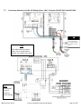
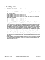
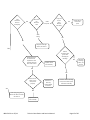
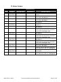
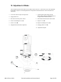
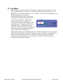
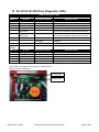
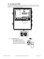
1
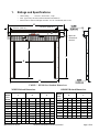
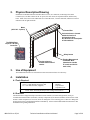
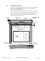
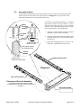
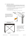
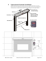
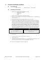
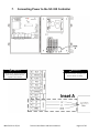
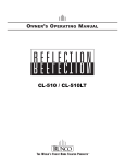
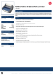
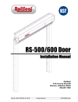
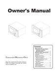
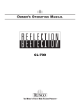
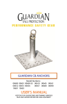
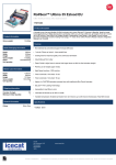
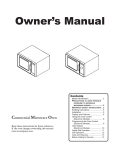
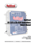
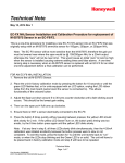
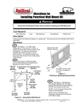
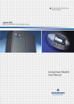
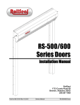
Technical Installation and Service
Manual
RollSeal
1733 County Road 68
Bremen, Alabama 35033
4801-5159 rev. 05/14
Technical Installation and Service Manual
Page 1 of 26
1.
Ratings and Specifications
•
•
•
Motor Rating………..240 VAC, Three Phase, 1/4 hp
Door approved by the NSF (National Sanitation Foundation)
Motor must be connected through controller. See SC-325 Manual (4801-5156).
E
14-1/8 in. (35.9 cm.)
5 3/4 in. (14.6 cm.)
Space for
access door
removal
B
C
A
D
TABLE 1 RS 500 Door Standard Dimensions:
WIDTH Related Dimensions
A
HEIGHT Related Dimensions
D
E
RS500
Door
Width
Ft.
In.
cm
Ft.
In.
cm
Ft.
In.
cm
4'(W)
4
0
122
5
4-13/32
164
6
8-15/16
206
RS500
Door
Height
B
C
Ft.
In.
cm
Ft.
In.
cm
7'(H)
7
0
214
8
8-11/16
266
7
6
229
9
2-11/16
281
5'(W)
5
0
153
6
4-13/32
194
7
8-15/16
236
7'6"(H)
6'(W)
6
0
183
7
4-13/32
225
8
8-15/16
267
8'(H)
8
0
244
9
8-11/16
296
6'6"(W)
6
6
198
7
10-13/23
240
9
2-15/16
282
9'(H)
9
0
275
10
8-11/16
327
7'(W)
7
0
214
8
4-13/32
255
9
8-15/16
297
10'(H)
10
0
305
11
8-11/16
357
11
0
335
12
8-11/16
387
12
0
366
13
8-11/16
418
8'(W)
8
0
244
9
4-13/32
286
10
8-15/16
328
11'(H)
10'(W)
10
0
305
11
4-13/32
347
12
8-15/16
388
12'(H)
11'(W)
11
0
335
12
4-13/32
377
13
8-15/16
419
12'(W)
12
0
366
13
4-13/32
408
14
8-15/16
449
4801-5159 rev. 05/14
Technical Installation and Service Manual
Page 2 of 26
2.
Physical Description/Drawing
Installation of a RollSeal RS-500 Automatic Door involves, at a minimum, connecting to the Smart
Controller (SC)-325 that connects to the AC power, the door motor, the Up/Down button, and the safety
beam. Other accessories can be added such as a remote IR sensor, a remote radio link, and door movement
indicators such as lights and bells.
Motor
(240 VAC - 3 phase)
Control Box
Limit switches are located
within the interior of
horizontal member.
See Section 8 for description
of limit switches.
The RS500 Door
requires a SC-325
Controller.
Safety beams
Floating Magnets and
Laminated Steel
(Attached to outside
of curtain and inside
track units)
Tension pipes are
located within folds of
curtain.
3.
Use of Equipment
The RollSeal RS-500-Door is an automatic motorized curtain enclosure for a doorway.
4.
Installation
4.1 Tools Required
3/8 in. (10 mm) Power screwdriver (portable)
3/16 in. (5 mm) Drill bit and power drill
3/8 x 1 in. Bolts and nuts (supplied)
Socket
Hammer
Tape measure
Carpenter's level
NOTE: Other Tools May Be Required According To Installation.
4.2 Overview
The RS-500-door is shipped with pre-assembled vertical members (left track and right track), and a preassembled horizontal member (head unit). Identify components by the Parts/Assemblies section in back of this
manual. When components are received, check for damaged or loose or missing parts. If there are damaged or
missing parts contact your RollSeal distributor immediately. Please read and understand all instructions in this
manual before beginning installation.
4801-5159 rev. 05/14
Technical Installation and Service Manual
Page 3 of 26
4.3
Adjusting the Clear Opening
Locate your particular system in Table 1, page 1. Read the value of height and width of the clear
opening for the door size that you are installing. This gives the required dimensions of the clear
opening. If necessary, adjust the dimensions of the mounting posts or framing members to the
height and width of your RS-500 door system as shown in Diagram 1. Refer to Section 4.4 (page
4, Diagram 2) for details of attaching door to framing members. Framing material must provide
suitable support for attachment of screws.
Make sure that mounting posts or framing members are positioned so that the screw holes of the
outer flanges of the vertical members will align with the mounting posts or framing members
(Section 6.4, page 8, Diagram 2). Make sure that there is room for the motor and control box
without encountering any obstructions.
Diagram 1
Front View (Curtain Side)
5.75 in.
(14.61 cm.)
4.125 in.
(10.45 cm.)
20.688 in
(52.55 cm.)
Overall height =Height + 20.688 in. (52.55 cm.)
10 in.
(25.40 cm.)
Space for
access door
removal.
Width (see Table 1
Page 1)
Height (see Table 1
Page 1)
Floor Level
8.2 in.
(20.83 cm.)
Overall Width = Width + 16.4 in. (41.66 cm.)
NOTE: Allow 1' (30.4 cm) minimum, preferably 18" (45.7 cm) clearance
above the Head Unit for future panel maintenance or replacement.
4801-5159 rev. 05/14
Technical Installation and Service Manual
Page 4 of 26
4.4
Attachment Points of Door
1.
When sizing the clear opening for attachment of the door, pay close attention to the following
guidelines. Door flanges have pre-drilled holes that serve as mounting points of door.
Flange widths are shown in Diagram 2.
Make sure that door assembly is plumb & square.
2.
The top unit has a top flange and a bottom flange. Make sure these flanges overlap framing.
3.
The vertical members have inner flanges and outer flanges. The outer flanges have pre-drilled
holes that serve as attachment points. Make sure the outer flanges overlap framing.
4.
When door is raised in front of clear opening (Section 4.7, page 6), Diagram flanges must be
flush against framing for attachment of screws.
1 in. (2.54 cm.)
Diagram 2
A
Holes in top flange are
pre-drilled.
1 in. (2.54 cm.)
Pre-drilled holes
for flange attachment
A
Holes in outer flange
are pre-drilled.
Section A-A
Framing
Members
1.25 in. (3.17 cm)
Outer flange
Bottom View
1.25 in. (3.17 cm.)
Inner flange
Framing Members
4801-5159 rev. 05/14
Technical Installation and Service Manual
Page 5 of 26
4.5
Assembly of Parts
Arrange the horizontal member, left vertical member (left track), and right vertical member (right
track) on the floor in front of the clear opening as shown in Diagram 3. The curtain side of the
horizontal member and each vertical member faces down.
A
End of
horizontal
member
B
U-shaped
plate
On each end of the horizontal member is a U-shaped
plate that fits inside each vertical member. The Ushaped plate has four bolt holes, two on the inside
and two on the outside flanges that match bolt holes
in the vertical member. See diagram at left.
1.
Align the vertical member with the U-shaped
metal plate at end of horizontal member.
2.
Slide the vertical member onto the outside of the
U-shaped metal plate of the horizontal member
as shown in A.
3.
Insert bolts through bolt holes as shown in B.
Install nuts. Tighten bolts & nuts securely.
3/8" x 1"
Bolts & nuts
Plate fits inside
vertical member
Slide vertical member
over U-shaped plate.
Vertical
Member
Right vertical member
Clear Opening
At this end of members
Diagram 3
Left vertical member
Placement of Parts for Assembly
Lay left track, right track, and horizontal
member face down in front of the clear opening
as shown.
Horizontal member
4801-5159 rev. 05/14
Technical Installation and Service Manual
Page 6 of 26
4.6
Infrared Sensor Connectors
Located at the bottom of each vertical member is an infrared detector. The detector on each vertical
member operates as a safety device if the infrared beam is interrupted. Door can be set to stop if
beams are broken while closing or to stop and reverse to the full open position. Refer to the RollSeal
SC-325 Controller Manual for more information.
1. Locate female connector on vertical member. This connector is attached to the infrared detector.
2. Locate male connector on horizontal member. Unroll cable until connectors meet.
3. Plug connectors together. Make sure connectors interlock.
4. Repeat for both infrared detectors.
5. Cable ties and adhesive mounts are supplied to secure wire to the inside of tracks.
Diagram 4
NOTE: For each vertical member, unroll
respective sensor cable attached to
horizontal member until cable reaches the
connector attached to the vertical member.
Plug connectors together. Some slack
must be left at photo eyes for replacement
purposes.
4.7
Fastening Door Assembly
to Clear Opening
The two diagonals must be within 1/8
inch.
1.
Use a tape measure and make sure that the
overall height and overall width of the
clear opening meet the requirements:
Overall Height = Height + 20.688 in.
(52.55 cm), Overall Width = Width +
16.4 in. (41.66 cm). Reference Table 1
and Diagram 1.
2.
Make sure that door assembly is plumb &
square. See Diagram 5.
Verify dimensions
from Table 1.
Diagram 5
4801-5159 rev. 05/14
Technical Installation and Service Manual
Page 7 of 26
3.
Center door assembly on clear
opening. Align the bottom of
each vertical member with the
respective framing board or
posts of the clear opening.
NOTE: The vertical members
should be aligned so that their
outer flanges will exactly
overlap with the framing
boards or posts when the door
assembly is raised into
position.
4.
Assemble workers and
equipment into position on
each side of the door assembly.
IMPORTANT: SLOWLY
LIFT TOP OF DOOR
ASSEMBLY TO RAISE THE
DOOR. See Diagram 6.
Diagram 6
Drill 1/4" Hole and
Install Hammer Set
Anchors
Diagram 7
5.
Lean door assembly upright against clear
opening.
6.
Carefully press flanges of the door
assembly flush against faces of framing
boards or posts.
7.
Fasten Tek screws (in steel) or lag screws
(in wood) through the flanges on sides of
door assembly. Securely tighten all
screws.
8.
On the lower and upper flanges of the
horizontal member there are attachment
points for fastening screws. Fasten Tek
screws (in steel) or lag screws (in wood)
4801-5159 rev. 05/14
through the holes. This secures the top of
the door to the clear opening.
9.
Locate the two floor mounting holes at
the bottom of the left & right tracks. See
Diagram 7.
10.
Drill a 1/4" hole and install Hammer Set
Anchors (1002-6030) in both right and
left tracks. See Diagram 7.
11.
This completes fastening of the door
assembly to the clear opening.
12.
Refer to controller section for the
next steps.
Technical Installation and Service Manual
Page 8 of 26
5.
Typical Smart Controller Installation
A typical installation of the Smart Controllers involve, at a minimum, connections to AC Power,
the door motor, the Up/Down button, and the Safety Beam. Other accessories can be added such as
a remote IR sensor, a remote radio link, and door movement indicators such as lights and bells.
Control Box and
Encoder Assembly
IR Detector
Limit and Safety
Switches are located
within the interior of
horizontal member.
Drive Motor
RS-500 or RS-600 Door
SC-325 or SC-650
Brake Release
Tension
Pipes
Safety Beam
Input Power
4801-5159 rev. 05/14
Technical Installation and Service Manual
Page 9 of 26
6
Controller Installation and Setup
6.1
Tools Required
Small screwdriver
6.2
Standard Screwdriver
Wire strippers
Installation Instructions
1.
Unpack system, and check that all components are present.
1
RollSeal Smart Controller
1
Installation Kit
1
Manual
2.
Hang the controller with four screws at the desired location.
3.
Make sure all power supplies are disconnected before breaking any wires, or reaching into the
controller enclosure.
4.
Determine the required Powering Voltage whether 115 VAC or 230 VAC.
5.
If the desired power supply voltage is different from the factory preset/prewired voltage, the
appropriate version Brake Rectifer must be ordered separately, field-installed on the RS Door,
and the SC controller switch & jumper settings changed accordingly. The SC-325 controllers
are factory preset to 115 VAC and the RS-500 doors factory prewired to require a 115 VAC
power supply. The SC-650 controllers are factory preset to 230 VAC and the RS-600 doors
factory prewired to require a 230 VAC power supply. The SC-325/SC-650 controllers and
RS-500/600 doors can be field upgraded to accommodate either 115 VAC or 230 VAC power
supply. Refer to Section 12.5 for the SC controller power wiring, switch setting, and jumper
setting and Section 12.6 for the Motor Brake Rectifier part numbers and wiring information.
WARNING!
Only a qualified electrician should install and/or
service this equipment.
Failure to observe precautions could result in
equipment damage, severe bodily injury, or loss of life.
WARNING!
Dangerous High Voltages!
Allow Approximately 5 Minutes For The Controller To
Power-Down Before Changing Switch Settings, Jumper
Placement, Or Wiring.
6.
Connect power.
7.
Connect AC/DC harness hook up. See diagram 8 on page 16
8.
Turn the controller on.
9.
Set the Open and Closed Speed and Limits, the Acceleration and Deceleration Ranges, Close
Time Delay and Switch positions as discussed in Section 5 of this manual.
10. Refer to door setup guide for next step. (see page 13)
4801-5159 rev. 05/14
Technical Installation and Service Manual
Page 10 of 26
7.
Connecting Power to the SC-325 Controller
WARNING!
WARNING!
Ensure the Drive AC Selection Jumper
and PCB 154 AC Selection Switch Are
Set Accordingly BEFORE Power Is
Applied To The Controller
4801-5159 rev. 05/14
Hardwire Facility Power As Required,
Either 120 V or 240 V. Set Jumper And
Selection Switch Accordingly
Technical Installation and Service Manual
Page 11 of 26
7.1
Connecting Switches to the SC-325 Wiring Option “-W01” Controller PN 6607-8057 and 6607-8058
W R N I N 9.1
Orange Wires Must
Be Capped Off If Not
Used With A Freezer
door
Note
All conduit and/or air spaces
where wire is routed must be
airtight. Use sealant if necessary
Note
Recommend
Using 18
Gauge For
Switch Wiring
4801-5159 rev. 05/14
Technical Installation and Service Manual
Page 12 of 26
8. Door Setup Guide
Note: DO NOT USE JOG Mode to do these tests
1. Press and hold the ‘MODE’ Button until P1 is shown in the display. Set P1 to 45 seconds for
the ‘Time Out’ function.
2. Press the ‘MODE’ button 1 time to P2. Set P2 to 20
3. Press the ‘MODE’ button 1 time to P3. Set P3 to 80
4. Press the ‘MODE’ button 1 time to P4. Set P4 to 3 (Note: This must be 3 for freezer CMS
Box to heat and blow air.
5. Press the ‘MODE’ button 1 time to P5. Set P5 to 25
6. Press the ‘MODE’ button 1 time to P6. Set P6 to 5
7. Press the ‘MODE’ button 1 time to P7. Set P7 to 25
8. Slowly press the ‘MODE’ button skipping P10, P11, and P12 until you see PS1 in the
display. It will indicate ‘no’ on the screen. Hit the up arrow on the controller to change ‘no’ to
‘yes.’ This is where you will begin to set the upper and lower limits of the door panel (fabric).
Hit the ‘MODE’ button again and the panel will move towards the HOME switch and then
back down towards the current setting of the OPEN limit. Use the up and down arrows to set
the upper limit between 20-24 in the display. Then press the ‘MODE’ button again and the
panel will move downwards toward the current CLOSE limit. Use the up and down arrows to
achieve the proper lower limit and ensure that the panel is resting firmly against the floor to
create a good seal (especially important for Freezer doors). If the door closes to the floor on
the first attempt, press the up arrow to bring the panel slightly off the floor and then press
the down arrow to achieve this seal. This will prevent slack in the panel which could result in
the panel auto reversing when it hits the floor. The number displayed will then become your
lower limit.
9. Press the ‘MODE’ button one last time to exit programming mode. Your lower limit that was
just set will remain in the display and you will have the green LED on the controller lit up
beside ‘ACTUAL POSITION.’
4801-5159 rev. 05/14
Technical Installation and Service Manual
Page 13 of 26
9. Troubleshooting Flowchart
Looking at the SC-325
or SC-650 display, what
is being displayed?
Three
Dashes
(---)
Unknown position indication,
See article 1
Alternates
between three
dashes (---) and a
numerical (718)
l
ii
Press an open button to reset
the actual position
Check egress strap to ensure that the strap
is in the correct reset Limit Mark position
and not pulled out of position.
Yes
Error
Code
A numerical
actual
position,
(718)
See article 2
Has the SWX2
selection switch &
drive selection
jumper been set
to match incoming
voltage?
Yes
Will the
door run in
jog mode?
No
No
Is the power
LED on the
motor drive
board steady
Yes
No
Set switch and
jumper then
restart flow chart.
4801-5159 rev. 05/14
Check incoming voltage at L1-L2 to motor
drive board. If present replace drive
board, if not check incoming supply.
Technical Installation and Service Manual
Page 14 of 26
Is the
obstruction
LED on in
the display?
When does
the
obstructio
n LED
Yes
While
Opened
While
Closing
Is any item
or door
panel
between
door safety
Remove item or
correct door
panel.
Yes
No
No
Adjust the lead edge
switch, see article 6.
Yes
Remove terminals
for direction and
sequential on door
assembly. Does the
door move in either
Will the
obstruction LED
go out while
activating the
lead edge
Yes
Replace control
door assembly
Adjust the
lead edge
switch, see
article 6.
No
No
Perform test in
article 5. Does
door operate
properly?
Problem is in
Accessory
switches added
to the door
Check for short in lead edge
circuit, if all ok then replace
control door assembly.
Yes
No
When trying to jog door,
what is the status of ST LED?
See article 4.
4801-5159 rev. 05/14
Replace control
door assembly.
Technical Installation and Service Manual
Page 15 of 26
10. Unknown Position Indication
There are occasions when the controller may
not know the exact position of the door, for
example, when returning from the Jog Mode. In
these cases the Display Indicator will display a
series of three bars as shown at the right. This
is known as the Unknown Position
Indication.
When the door is actuated, the door will
proceed to the full open position, however the speed of the door will be reduced. When the
door has returned from the home switch position to the open limit position, the display will
show the actual position of the door. This indicates that the door has reset its position and is
ready for normal operation.
If something in the door encoders fails the control will not be able to recognize the position
of the door. This problem can also arise from a loose or bad connection in the DC harness.
Check to make sure the harness is connected properly and that there aren’t any loose wires in
the connections of the encoders.
Diagram 8
Lead Edge
Switch
Safety Switch
Home Switch
Control Box
DC Plug
AC Plug
Encoder
DC Harness
4801-5159 rev. 05/14
Technical Installation and Service Manual
Page 16 of 26
11. Error Codes
Mechanical Errors
Code
EO1
Condition
Opening,
Home Switch
EC1
Closing,
Home Switch
Home Switch
EO2
Opening,
Safety Switch
Safety Switch
EC2
Closing,
Safety Switch
Safety Switch
EO3
Opening,
Safety Switch
Home & Safety
EC3
Closing,
Safety Switch
Home & Safety
4801-5159 rev. 05/14
Panel Movement
Problem Area
Home Switch
Possible Solutions
Try to activate door normally (open), should
fix itself
Use JOG mode to lower door panel below
Home switch, See Article 3
Manually release brake and pull panel below
Home switch, See figure 1
Home Switch Arm may be loose. Retighten,
See Article 6
Lower limit is not set correctly, Reset door
limits PS 1
Home Switch Arm may be loose. Retighten,
See Article 6
Faulty connections, check DC harness (Grey
Cable) at the door and the DC connections
on the PCB154 See figure 2 & 3
Safety Switch Arm may be loose.Retighten,
See Article 6
Faulty connections, check DC harness (Grey
Cable) at the door and the DC connections
on the PCB154 See figure 2 & 3
Safety Switch Arm may be loose.Retighten,
See Article 6
Faulty connections, check DC harness (Grey
Cable) at the door and the DC connections
on the PCB154 See figure 2 & 3
Manually release brake and pull panel below
Home switch, See figure 1
Check DC harness connection, especially if
"Door Obstruction" LED is on. See figure 2.
Manually release brake and pull panel below
Home switch
Check DC harness connection, especially if
"Door Obstruction" LED is on. See figure 2.
Technical Installation and Service Manual
Page 17 of 26
Feedback Errors
Code
EOF1
Condition
Opening,
Encoder Fault
Panel Movement
Up or Down
Problem Area
Encoder
None
Brake
Brake Relay
Brake Rectifier
Brake
Assembly
Egress Strap
Tension pipe
pockets
Drive Board
ECF1
Closing,
Encoder Fault
ECF1
Up or Down
Encoder
None
Brake
Brake Relay
ECF1
EOF2
Opening,
Direction Fault
Up then panel
stops and rolls
down a few inches
Up
Down
Brake Rectifier
Brake
Assembly
Drive Overload
Trip
Encoder
Drive
Drive
Drive
Egress Strap
ECF2
Closing,
Direction Fault
4801-5159 rev. 05/14
Up
Drive
Down
Encoder
Possible Solutions
Check DC harness, make sure optics are clean,
inspect encoder wire connections in door's J-box
and on PCB154 board. See figure 1 & 2
To prove the brake is not releasing automatically,
disengage manual brake release (See figure 1)
and attempt to operate door. If it operates, one
or more of the following is the problem.
Check brake relay on PCB154 control board.
See Article 7
Check brake rectifier in motor. See Article 7
Make sure brake is not adjusted too tight or that
the brake assembly is defective, See figure 4
Check egress strap to ensure that the strap is in
the correct reset Limit Mark position and not
pulled out of position.
Ensure correct pipe location in panel pockets.
Inspect pipes for bends.
Ensure both PWR and ST LEDs are “ON” steady
See Article 4.
Check DC harness, make sure optics are clean,
inspect encoder wire connections in door's
junction box and on PCB154 control board. See
figure 2 & 3
To prove the brake is not releasing automatically,
disengage manual brake release (See figure 1)
and attempt to operate door. If it operates, one
or more of the following is the problem.
Check brake relay on PCB154 control board.
See Article 7
Check brake rectifier in motor. See Article 7
Make sure brake is not adjusted too tight or that
the brake assembly is defective, See figure 4
If a drive overload occurs due to over-current,
over-voltage, or temperature levels out of range,
the drive may trip while the door is opening.
Signal W ires (A, B) reversed. See figure 3
Reverse two phases to the motor
The drive or the gear motor may not be
functioning.
If the gear motor seems to be functioning, then
two phases to the motor must be reversed.
Check egress strap to ensure that the strap is in
the correct reset Limit Mark position and not
pulled out of position.
Reverse two phases to the motor
Signal W ires (A, B) reversed. See figure 3
Technical Installation and Service Manual
Page 18 of 26
12. Adjustment of Brake
After extended operation of the brake lever, the brake may become worn. As the brake wears, some adjustment
to the brake is required. Lettered diagrams below correspond to lettered instructions. Follow instructions to
adjust brake:
1.
Close door curtain to fully lowered position.
2.
Engage Brake lever.
3.
7.
Tighten spider nut (C) snuggly against
blower wheel. Make sure a tab of spider nut
is aligned with a notch in the shaft
Disconnect electrical power to motor.
8.
Bend tab (C) downward into notch of shaft.
4.
Remove four Phillips screws (A).
9.
Replace cover (B).
5.
Remove cover (B).
10. Replace four Phillips screws (A).
6.
Straighten the bent tab (C) of spider nut.
11. Disengage brake lever (D).
12. Adjustment complete.
C
B
A
4801-5159 rev. 05/14
D
Technical Installation and Service Manual
Page 19 of 26
13. Jog Mode
The Jog Mode will permit an operator to manually control the position of the door with the
Up ( ) and Down ( ) arrow buttons. To enter the Jog Mode, press both the Up ( ) and
Down ( ) arrows at the same time for at least 5 seconds. The controller will indicate the Jog
Mode in the display as shown below.
In the Jog Mode the door can be opened and
closed and is not affected by the Home limit
switch or the Safety beam. Therefore, the
operator must carefully watch the door
JOG
movement when nearing the full open and full
closed positions. To exit the Jog Mode, press
and hold the Up ( ) and Down ( ) arrow
buttons for at least 5 seconds. The controller will
return to the normal operating mode with the
Actual Position shown in the display.
When returning to the normal operating mode, the controller will not know the exact position
that the operator has left the door when exiting the Jog mode. Therefore, the controller will
display a series of three horizontal bars. Upon the next command the door will slowly
proceed to the full open position to reset its memory. The door will always follow this
procedure after exiting the Jog Mode.
4801-5159 rev. 05/14
Technical Installation and Service Manual
Page 20 of 26
14. SC-325 & SC-650 Drive Diagnostic LEDs
KB Drive Diagnostic LEDs
Door Idle
PWR LED
OFF
ST LED
Operating Condition
Drive is Off
Normal Condition
AC Input Undervoltage
Green
Green
Steady Yellow
Quick Flash
Red/Yellow
Slow Flash
Red/Yellow
Steady Red
Red/Yellow/Green
Door
Moving
PWR LED
Green
Green
Green
ST LED
Slow Flash Green
Quick Flash Red
Slow Flash Red
Operating Condition
Normal Condition
Overcurrent
Short Circuit
Green
Green
Green
OFF
Possible Causes
No AC Power Applied
Fuse Blown
Defective Drive
Input AC=115 Vac/Drive Jumper set on 230 Vac
AC Input Overvoltage
Current Overload
Undervoltage or
Overvoltage
Input AC=230 Vac/Drive Jumper set on 115 Vac
Drive tripped due to current overload
Drive tripped due to out of range voltage
condition
Possible Causes
Drive operating at 120%-200% of full rated load
Two phases may be shorted
Phase may be shorted to ground
Gear motor may be defective
Slow Flash = LED flashes 1 second off, 1 second on
Quick Flash = LED flashes 0.25 second off, 0.25 second on
Steady = LED is constantly on
Power LED
Status LED
4801-5159 rev. 05/14
Technical Installation and Service Manual
Page 21 of 26
15. Test Direction SWX
SWX2
To perform all tests below you must have a short piece of wire. This wire could be 5 inches
long and can be 16/18 gage in size. Each test performed will be located in the same area of
the PCB 154 of the door assembly as below.
J10
Voltage
Selection
Switch
SWX1
PCB154 Rev ‘D’
U7
DC Power
J3
V6 Drive
Jumper
J8
J7
ENCODER
SAFETY BEAM
LIMITS
Out
Close
Open
Out
Sequential SWX
Stop
Out
Manual
Timed
Home
Lead
Edge
Safety
Gnd
Signal
Gnd
+12v
Signal
J9
DIRECTION SWX
Brake Auxiliary
J11
J6
J1
Connector A
(V6 Drive)
RLY2
J5
J2
Anode
Gnd
+12V
J12
VCC
F1
1.2 Amp
U1
Connector B
(1ph Drive)
93LC66
RLY1
Inset A
15.1. Test Open Direction
a. Place the jumper on the pins of
Out to Open momentarily. Care
should be taken that this wire only
touches these two points. The door
should open to its full open position.
4801-5159 rev. 05/14
Technical Installation and Service Manual
Page 22 of 26
15.2 Test Close Direction
a. Place the jumper on the pins of Out to
Close momentarily. Care should be
taken that this wire only touches these
two points. The door should close to
its full close position.
15.3 Test Stop Position
a. Place the jumper on the open or close
direction momentarily, the door will
start to move in that direction. Care
should be taken that this wire only
touches these two points. Before the
door gets to its full limit place the
jumper across the Out to Stop
position momentarily. The door
should stop at this point.
Test Sequential SWX
15.4 Test Manual Position
a. Place the jumper on the pins of Out to
Manual momentarily. Care should be
taken that this wire only touches these
two points. The door should open or
close to its full limit position. The
direction will depend on the last time
it received an input from this location.
Each time you make contact on this
point the door will move opposite of
the previous move.
15.5 Test Timed Direction
a. The door must be closed before performing this test. Place the jumper on the
pins of Out to Timed momentarily.
Care should be taken that this wire
only touches these two points. After
the door is opened and all safety
sensors are clear, a timer would count
down and close the door
automatically. In order for the timed
feature to work, the door must have
initially been in a closed or stopped
position. If the door was already
opened by an open test or some other
means, the timer would not operate and the door would remain open.
4801-5159 rev. 05/14
Technical Installation and Service Manual
Page 23 of 26
16. Test Brake Relay
The gear motors on these RS 500/600 series door has a brake rectifier which will activate the
brake in the gear motor to stop the unit when not in use. There is a relay (acting as a switch)
on the PCB 154 board in the door assembly of the control that will turn this brake on and off.
This test procedure will allow you to test the relay to see if it is failing or if the problem
could be in the brake rectifier. First we need to test the brake relay on the PCB 154. The
connections are found at the bottom right corner of the board.
PCB 154
Brake Terminal
If the brake relay is at fault the door will struggle to operate or it could cause the drive board
to trip and there would be an Error code of EOF1 or ECF1 in the display of the control.
To test the brake relay:
1. Remove quick connect connector from the PCB 154 board.
2. The door must be operated in one direction while in the jog mode. See Article 3.
3. While pressing the up or down arrow while in jog mode place a jumper across the
connectors inside the quick connect which will act as a switch like the relay would
normally do. See figure 1.
This should release the brake and allow the door to operate. If the door does operate after
performing step three then replace the door assembly of the control.
4801-5159 rev. 05/14
Technical Installation and Service Manual
Page 24 of 26
17. RollSeal Automatic Door Wiring Diagram
4801-5159 rev. 05/14
Technical Installation and Service Manual
Page 25 of 26
18. RollSeal Smart Controller Wiring Diagram
4801-5159 rev. 05/14
Technical Installation and Service Manual
Page 26 of 26