1
LBI-39100
Maintenance Manual
EDACS®
C3 MAESTRO™ CONSOLE SYSTEM
WITH ENHANCED AUDIO
ENCLOSURE
TABLE OF CONTENTS
INSTALLATION AND SET-UP .......................................
I/O BACKPLANE BOARD ...............................................
AUDIO SYSTEM BOARD................................................
SPEAKER KITS AND ASSEMBLIES..............................
ericssonz
LBI-39101
LBI-39102
LBI-39103
LBI-39104
LBI-39100
CREDITS
EDACS is a registered trademark of Ericsson Inc.
C3 Maestro is a trademark of Ericsson Inc.
Hewlett-Packard and HP are registered trademarks of Hewlett-Packard Company.
IBM is a registered trademark of International Business Machines Corporation.
PC-AT is a trademark of International Business Machines Corporation.
MS-DOS is a registered trademark of Microsoft Corporation.
NOTICE!
This manual covers Ericsson and General Electric products manufactured and sold by Ericsson Inc.
NOTICE!
Repairs to this equipment should be made only by an authorized service technician or facility designated by the supplier. Any
repairs, alterations or substitution of recommended parts made by the user to this equipment not approved by the
manufacturer could void the user’s authority to operate the equipment in addition to the manufacturer’s warranty.
NOTICE!
The software contained in this device is copyrighted by Ericsson Inc. Unpublished rights are reserved under the copyright
laws of the United States.
This manual is published by Ericsson Inc., without any warranty. Improvements and changes to this manual necessitated by typographical errors,
inaccuracies of current information, or improvements to programs and/or equipment, may be made by Ericsson Inc., at any time and without notice. Such
changes will be incorporated into new editions of this manual. No part of this manual may be reproduced or transmitted in any form or by any means,
electronic or mechanical, including photocopying and recording, for any purpose, without the express written permission of Ericsson Inc.
Copyright© March 1995, Ericsson Inc.
2
LBI-39100
TABLE OF CONTENTS
Page
SPECIFICATIONS .........................................................................................................................................
3
INTRODUCTION ...........................................................................................................................................
7
DESCRIPTION ...............................................................................................................................................
PERSONAL COMPUTER......................................................................................................................
Video Display Monitor ("CRT").........................................................................................................
Standard PC Keyboard........................................................................................................................
CEC/IMC Serial Link..........................................................................................................................
Enhanced Audio Enclosure Serial Link...............................................................................................
DISPATCH KEYBOARD ("CUSTOM KEYBOARD")......................................................................
ENHANCED AUDIO ENCLOSURE .....................................................................................................
Enhanced Audio Enclosure Contrast From Earlier Design Audio Tower ...........................................
Case Assembly ....................................................................................................................................
Power Supply ......................................................................................................................................
I/O Backplane Board...........................................................................................................................
Audio System Board ...........................................................................................................................
SPEAKERS KITS AND ASSEMBLIES ................................................................................................
CALL DIRECTOR PATCH ...................................................................................................................
7
7
7
9
9
9
9
10
10
10
11
11
11
12
13
OPERATING PROCEDURES....................................................................................................................... 13
INSTALLATION AND SET-UP.................................................................................................................... 13
MAINTENANCE ............................................................................................................................................
DISASSEMBLY INSTRUCTIONS ........................................................................................................
Enhanced Audio Enclosure .................................................................................................................
Speaker Assembly ...............................................................................................................................
13
13
13
14
OUTLINE DIAGRAM
C3 MAESTRO CONSOLE SYSTEM .................................................................................................... 15
Parts List ............................................................................................................................................. 15
ASSEMBLY DIAGRAM
ENHANCED AUDIO ENCLOSURE ..................................................................................................... 16
Parts List ............................................................................................................................................. 17
INSTALLATION INSTRUCTIONS
ENHANCED AUDIO ENCLOSURE RACK-MOUNT KIT; OPTIONAL ........................................ 18
SPECIFICATIONS *
GENERAL
AC Power Operating Voltage
100 − 240 Vac (automatic 115/230 Vac selection)
AC Power Operating Frequency
47 − 63 Hz
AC Power Consumption
Complete Console System
Enhanced Audio Enclosure & Speakers
Personal Computer System
Temperature Range (ambient air temperature)
Operating
Storage
375 watts maximum
80 watts maximum
(See manufacturer's specifications)
50° to 104° Fahrenheit (10° to 40° Celsius)
-30° to 122° Fahrenheit (-34° to 50° Celsius)
3
LBI-39100
Relative Humidity (Enhanced Audio Enclosure only)
Operating
Storage
Dimensions (height x width x depth; approximate)
Enhanced Audio Enclosure
Speakers
Desk-Top (less volume knob)
Rack-Mount (less volume knob)
Personal Computer System
Rack-Mount Height; Optional (EIA 19-Inch std.)
Enhanced Audio Enclosure
Rack-Mount Speaker
Weight (approximate)
Enhanced Audio Enclosure
Enhanced Audio Enclosure w/ Rack Mount Option
Speakers
Desk-Top
Rack-Mount with two Speaker Assemblies
Cabling
Personal Computer System
Enhanced Audio Enclosure Case Construction
REGULATORY
Power Supply Safety and Performance
115 Vac Operation
230 Vac Operation
Leased Line Interface
Radio Frequency Interference (RFI)
Electro-Magnetic Immunity (EMI)
20% to 80%, non-condensing
10% to 90%, non-condensing
3.25 x 15 x 9.8 inches (8.26 x 38.10 x 24.98 cm)
6.38 x 6.25 x 3.69 (16.3 x 15.8 x 9.3 cm)
5.25 x 19 x 3.38 (13.34 x 48.26 x 8.59 cm)
(See manufacturer's specifications)
2 rack units (3.5 inches / 8.89 cm)
3 rack units (5.25 inches / 13.34 cm)
11.7 lbs. (5.31 Kg)
14.0 lbs. (6.35 Kg)
2.1 lbs. (0.95 Kg)
4.2 lbs. (1.91 Kg)
6.0 lbs. (2.72 Kg)
(see manufacturer's specifications)
0.060-inch sheet metal construction capable of supporting up
to 80 pounds (36.3 kilograms) when free-standing on a flat
surface (not rack mounted)
Meets ANSI/UL 1950 and CSA C22.2 No. 950-M89
requirements
Meets EN 60950-1992 and BS 7002 requirements
Meets UL 1459, IEC 950, EN 60950 and BS 7002
requirements
Meets requirements of FCC Part 15 and EN 55022 for Class A
equipment
Meets IEC 801 Parts 2, 3 and 4 for ESD, radiated RF
immunity and power line bursts respectively
CONTROL DATA LINKS
CEC/IMC ⇔ Personal Computer (PC)
9.6k or 19.2k baud RS-232 or RS-422 full-duplex serial
connection between the console's Personal Computer (PC) and
the Console Interface Module (CIM) within the CEC/IMC.
Full-duplex 4-wire data modems may be employed between
the PC and CIM in a remote console installations.
Personal Computer ⇔ Enhanced Audio Enclosure
9600 baud RS-232 full-duplex serial connection
Enhanced Audio Enclosure ⇔ Optional Equipment
RS-422 serial I/O port provided at rear panel of Enhanced
Audio Enclosure for control data interfacing to optional
equipment (for future expansion use)
AUDIO INPUTS
Microphones
Supervisor and Operator Headsets
4
Inputs for two simulated carbon telephone-style headset
microphones similar to Plantronics model HS-0309-1. Approx.
input impedance = 150 ohms. Typical input = 100 mV rms
(-12 dBm). Nominal input range = -18 to -6 dBm. ALC
controlled. DC mic bias = 3.0 ±0.5 Vdc with 50-ohm load.
LBI-39100
Desk Mic
Boom or Gooseneck Mic
Line 1, 2, 3 & 4
Call Director Patch
Paging Encoder
OTHER INPUTS
Microphone PTT And Monitor Switch
Microphone Sense
Page PTT
Call Director Hook Sense & Jack Sense
Input for an electret-type microphone similar to part number
19C851086P10 or P11. Approx. input impedance = 600 ohms.
Typical input = 70 mV rms (-21 dBm). Nominal input range =
-27 to -15 dBm. ALC controlled. DC mic bias = 3.7 ±0.5 Vdc
with 1000-ohm load.
Input for a dynamic microphone similar to Shure Bros. model
VR300 (part number 19C337100P1). Approx. input
impedance = 10K ohms. Typical input = 5 mV rms (-56 dBm).
Nominal input range = -68 to -44 dBm. ALC controlled. No dc
mic bias present.
Balanced 2-wire 600-ohm inputs each designed to receive
voice bandwidth audio from one pair of a 4-wire 600-ohm
twisted-pair transmission system provided by the CEC/IMC.
Transformer isolated. Typical input = 436 mV rms (-5 dBm).
Nominal input range = -20 to +10 dBm. Ground isolation =
greater than 1500 Vdc.
Balanced 2-wire 600-ohm input designed to accept audio from
a Call Director device similar to Plant Equipment model 3780L1-TT-010. Transformer isolated. Typical input = 78 mV rms
(-20 dBm). Nominal input range = -26 to -14 dBm.
Balanced 2-wire 600-ohm input designed to accept audio from
a paging tone encoder or similar device. Typical input =
436 mV rms (-5 dBm). Nominal input range = -11 to +1 dBm.
Ground isolation = greater than 1500 Vdc.
Active-low inputs used to detect "dry-contact" switch closures
of the type found in standard microphones, footswitches and
headset jacks. Typical open-circuit voltage = 12 Vdc. Max.
open-circuit voltage = 16 Vdc. Max. short-circuit current = 30
mA. Low-pass filtering prevents undesirable signals such as
switch contact bounce or static charges from triggering
microcontroller circuits; typical microcontroller response
time = input must be valid for greater than 5 milliseconds.
Active-low inputs used to sense the connection of a
microphone. Typical open-circuit voltage = 12 Vdc. Max.
open-circuit voltage = 16 Vdc. Max. short-circuit current = 30
mA. Low-pass filtering prevents undesirable signals such as
switch contact bounce or static charges from triggering
microcontroller circuits; typical microcontroller response
time = input must be valid for greater than 5 milliseconds.
Active-low input used to signal presence of paging signal on
paging audio input. Typical open-circuit voltage = 12 Vdc.
Max. open-circuit voltage = 16 Vdc. Max. short-circuit current
= 30 mA. Low-pass filtering prevents undesirable signals such
as switch contact bounce or static charges from triggering
microcontroller circuits; typical microcontroller response
time = input must be valid for greater than 5 milliseconds.
Single-ended logic inputs used to sense CD off-hook and
handset connection status. Each internally pulled to +12 Vdc
via 470-ohm resistor.
5
LBI-39100
AUDIO OUTPUTS
Earphones
Supervisor and Operator Headsets
Speakers
Select and Unselect(s)
Line 1, 2, 3 & 4
Call Director Patch
Select & Unselect Recorders
AUDIO INPUTS AND OUTPUTS
Total Harmonic Distortion
Hum and Noise
Crosstalk
Level Adjustment
RELAY CONTACT OUTPUTS
Standard
Call Director On-Hook
*
6
Outputs for telephone-style headset earphones similar to
Plantronics model HS-0309-1 or ACS model XW/AT.
Approx. output impedance = 300 ohms. Unbalanced. Typical
output level = 100 mV rms. (-15 dBm). Nominal output range
= -21 to -9 dBm. Sidetone provided.
Typical Enhanced Audio Enclosure output level to Speaker
Assembly = 436 mV rms (-5 dBm). Maximum speaker audio
output power = 2 or 5 watts; selectable via internal switch at
each Speaker Assembly. Each Speaker Assembly is equipped
with a volume control. Minimum volume level provided;
enable/disable switch provided at each Speaker Assembly.
Maximum number of unselect speakers = 3.
Balanced 2-wire 600-ohm outputs each designed to transmit
voice bandwidth audio to one pair of a 4-wire 600-ohm
twisted-pair transmission system provided by the CEC/IMC.
Transformer isolated. Typical output = -5 dBm. Nominal
output range = -20 to +10 dBm. Ground isolation = 1500 Vdc
and greater than 5M ohms.
Balanced 2-wire 600-ohm output designed to deliver audio to
a Call Director device similar to Plant Equipment model 3780L1-TT-010. Typical output = -5 dBm. Nominal output range =
-11 to +1 dBm.
Unbalanced outputs each designed to drive audio inputs of an
external recording device. Approx. output impedance =
350 ohms. Capacitively coupled. Typical output = -5 dBm.
Nominal output range = -8 to -2 dBm.
Less than 1% from 300 to 3000 Hz
Less than or equal to -55 dB at 1 kHz
Less than or equal to -55 dB at 1 kHz
All audio input and output levels adjustable via digital
potentiometers using application program running on PC
Form-C (SPDT dry contacts) relay connections isolated from
ground and all other signals. One relay activates on console
PTTs. Two others are activated via reserved keystrokes at the
Dispatch Keyboard. Contact rating = 0.75 amps at 26 Vdc.
Ground isolation = 500 Vrms (60 Hz). Open contact isolation
= 500 Vrms (60 Hz).
Form-A (SPST normally-open dry contacts) relay connections
isolated from ground and all other signals. Activates (closes)
when console disconnects CD from CEC/IMC. Contact
rating = 0.75 amps at 26 Vdc. Ground isolation = 500 Vrms
(60 Hz). Open contact isolation = 500 Vrms (60 Hz).
These specifications are intended primarily for the use of the serviceman. See the appropriate Specifications Sheet for complete specifications.
LBI-39100
INTRODUCTION
The EDACS® C3 Maestro™ console system is a stateof-the-art CRT-based dispatch console system designed to
interface to an EDACS® CEC/IMC Digital Audio Switch.
Equipped with an Enhanced Audio Enclosure, the
C3 Maestro™ provides advanced console dispatch features
for EDACS radio system networks. The complete system
consists of:
•
•
•
•
•
•
•
•
an IBM® PC-AT compatible Personal Computer
(PC) system running MS-DOS® operating system
software and custom C3 Maestro application
software developed by Ericsson Inc., a color video
display monitor ("CRT") and a standard PC
keyboard
a Dispatch Keyboard (sometimes referred to as the
"Custom Keyboard")
an Enhanced Audio Enclosure which provides
audio conditioning, routing and amplification
functions for the console's audio signals, and
interface/control of external devices such the
Dispatch Keyboard and for example, if the console
is so equipped, a Call Director (optional
equipment) for telephone patch operations
desk-top or rack-mounted speakers (typically two –
one "select" and one "unselect")
other optional accessories such as headsets,
microphones and footswitches
cabling which interconnects the Enhanced Audio
Enclosure to the PC and speakers
cabling which interconnects the Enhanced Audio
Enclosure and the PC to the CEC/IMC (control
data and audio links; 100-foot cables supplied)
if the console is a remote console (not co-located
with the CEC/IMC), optional data modem
equipment for the CEC/IMC ⇔ C3 Maestro
control data link is required
NOTE
NOTE
Refer to LBI-38662 for a complete description of
the EDACS CEC/IMC Digital Audio Switch.
The C3 Maestro console's video display monitor
("CRT") and keyboard replace the array of controls and
indicators found on traditional modular/desktop-type
consoles. Standard console-type headsets, microphones, and
footswitches can be connected to the C3 Maestro. Also, a
variety of other external inputs and outputs are supported
from items such as a pager, call-check recorders and Call
Director telephone patch equipment.
Using the C3 Maestro console, a dispatcher can monitor
and communicate with a large number of personnel on the
EDACS CEC/IMC wide area network. Just like an EDACS
mobile or portable radio, each EDACS C3 Maestro console
is assigned a unique logical ID (LID) number. A typical C3
Maestro console installation is shown in the outline diagram
on page 15.
The PC's video display monitor displays graphical
representations of the radios being monitored or controlled
by the dispatcher. Using the Dispatch Keyboard, a
dispatcher can issue commands to control receive and
transmit audio signal routing between the CEC/IMC and
audio devices connected to the C3 Maestro such as
microphones and speakers. The C3 Maestro application
software program running on the PC in-turn controls
circuitry inside the Enhanced Audio Enclosure. This is
accomplished via an RS-232 serial link between the PC and
the Enhanced Audio Enclosure.
DESCRIPTION
PERSONAL COMPUTER
The PC within the C3 Maestro console system provides
most computer processing functions for the console.
Software includes the Microsoft's MS-DOS® operating
system and a custom C3 Maestro application program
developed by Ericsson Inc. This custom program
automatically starts when the computer is "booted". PC
components also include the video display monitor ("CRT")
and a standard PC keyboard.
Video Display Monitor ("CRT")
The PC's video display monitor provides all visual
dispatch control indications to the operating dispatcher. This
color monitor is typically of a VGA or super-VGA
resolution. Basic screen layout is shown in Figure 1. Screen
areas include:
•
Module Display Area − Fourteen (14)
communication modules are displayed at all times
in the upper portion of the screen. Each module
provides instant communication access to a talk
group, an individual unit, a conventional channel,
or another console. Eight (8) pages of fourteen (14)
modules are available for a total of 112 unique
communication modules. Each module can be
programmed by the console operator.
7
LBI-39100
•
Module Page Area − This area, located in the top
right-hand side of the screen, indicates which one
of the eight (8) module pages is displayed. When a
call is received on a non-displayed page, the
respective page indicator is high-lighted in yellow.
If an emergency call is received on a non-displayed
page, the indicator is high-lighted in red.
unselect calls is provided. For each call, this
detailed list includes caller and callee ID numbers,
time the call started, type of call, site used by
caller, and the call's module information. A scroll
list is not shown in Figure 1.
NOTE
NOTE
•
System Status Area − This area indicates various
status information such as console number, name or
ID number of the caller, emergency status, EDACS
operational status (full-feature trunking, failsoft
trunking, etc.), Call Director telephone patch status
and line 1 audio level via a VU meter. A VU meter
is not shown in the Figure 1.
In the dispatch environment, "select" audio is audio
received from the dispatcher's primary or
"selected" entity (group, individual, conventional
channel, etc.) and "unselect" audio is audio
received from all other entities which are currently
programmed into communication modules.
•
Note Card Area − Note cards provide instructions
and menus for module programming functions
which are referred to as "module modify"
operations. Note cards also provide advanced
dispatch operations such as patch and simulselect
set-up. These cards are located on the left-hand side
of the screen below the modules.
•
•
Call History and Scroll Area − This area, located
in the lower right-hand side of the screen, displays
the last five (5) select calls and the last five (5)
unselect calls received. The list is displayed on a
caller-to-callee basis. In addition, a detailed scroll
list of the last thirty-two (32) select and thirty-two
System Message/Command Line Area − This
area, located at the bottom left-hand side of the
screen, displays prompts and operator-entered data
such as radio ID numbers. Various system
messages are also displayed in this area such the
up/down status of the CEC/IMC-to-console control
data communication link (console-to-CIM link) and
successful/unsuccessful execution of a patch or
simulselect. No messages/commands are shown in
the Figure 1.
•
Clock Display − A continuous time display is
provided (12 or 24-hour format selectable ) in the
lower right side of the screen. This time is set and
A1
A1
POLICE-1
POLICE-1
A2
POLICE-2
A3
POLICE-3
A4
FIRE-1
A5
FIRE-2
A6
A7
A11
A12
A13
A14
PVT
A8
TRACEY P
A9
JONES BM
A10
FARRIS P
MODULE MODIFY
F1 = Program Unit
F2 = Program Group
F3 = Program Conventional
F4 = Program Phone
F5 = Program Console
F9 = Delete (Unprogram)
F10 = Save Module Setup
15511
ADAMS BM
BROOK TP
DELL JP
FARRIS P
AP
GULF
LM
HICKS QP
JONES BM
KELLY TM
MAN
TM
NANCE WM
SMITH JP
PAGE
PAGE-A
PAGE-B
PAGE-C
PAGE-D
PAGE-E
PAGE-F
PAGE-G
PAGE-H
STATUS
CON02
TRNK
SU_1
UNSELECT HIST
DELL JP to
BROOK TP to
DELL JP to
JONES BM to
JONES BM to
POLICE-2
POLICE-2
POLICE-2
POLICE-2
FIRE-1
SELECT HIST
KELLY TM to
SMITH JP to
FARRIS P to
SMITH JP to
JONES BM to
POLICE-1
POLICE-1
POLICE-1
POLICE-1
POLICE-1
Figure 1 − C3 Maestro Video Display Monitor (Typical; Module Modify Operation Shown)
8
LBI-39100
console (PC's COM1 port ⇔ console's modem) and the
local serial link at the CEC/IMC (CIM ⇔ CIM's modem)
are typically wired via RS-232 hook-ups. Normally, these
RS-232 links are configured for 9600 baud operation.
maintained by the CEC/IMC Manager (MOM PC).
Therefore, all CEC/IMC consoles' clocks are
synchronized to the CEC's/IMC's time thus
providing consistent time displays at all consoles.
Detailed console ⇔ CEC/IMC wiring and configuration
information is contained within the Installation And Set-Up
manual, LBI-39101. LBI-39101 is included with this
manual set.
Standard PC Keyboard
During dispatch operations, the standard PC keyboard is
not used. However, during the console set-up process,
access to this keyboard is required for basic file
management, configurations and maintenance operations.
This keyboard is also used to exit and re-execute the C3
Maestro's application program if/when additional
configuration, diagnostic and/or maintenance procedures are
required.
Enhanced Audio Enclosure Serial Link
In most cases, the PC's COM2 serial port is used for
control data communications between the PC and the
Enhanced Audio Enclosure. This serial port is wired for
RS-232 operation at 9600 baud. Control data transferred
over this duplex serial link includes Enhanced Audio
Enclosure-to-PC messages such as Dispatch Keyboard
keystrokes and VU meter data, and PC-to-Enhanced Audio
Enclosure messages such as start-up initialization
commands, recorder audio switching, and Call Director
audio switching. See the Installation And Set-Up manual,
LBI-39101 for wiring and configuration information.
CEC/IMC Serial Link
Normally, a C3 Maestro console system equipped with
an Enhanced Audio Enclosure uses the PC's COM1 serial
port for control data interfacing to the Console Interface
Module (CIM) within the CEC/IMC Digital Audio Switch.
This serial data link can be wired for RS-232 (3-wire) or
RS-422 (4-wire) operation. Typically, a C3 Maestro is colocated with the CEC/IMC and wired for RS-422 operation
at 19,200 baud. In a co-located installation, console ⇔ CIM
serial control data links up to 4000 feet (1219 meters) in
length may be employed if RS-422 interfacing is utilized.
DISPATCH KEYBOARD
("CUSTOM KEYBOARD")
The C3 Maestro's specially designed Dispatch
Keyboard provides tactile feedback button operation for
dispatch speed equal to a modular-type console. In addition,
the keyboard provides easy control for the advanced features
of the C3 Maestro console. Keys with similar functions are
grouped together and the most frequently used key groups
If the console is not co-located with the CEC/IMC, fullduplex 4-wire data modems and dedicated 4-wire data grade
phone lines (or equivalent) may be employed between the
CEC/IMC and the remote C3 Maestro console. In an
installation of this type, both the local serial link at the
ESC
F1
F2
F3
F4
F5
F6
F7
F8
F9
C3 Maestro
F10
COMMON CONTROL FUNCTIONS
SIMULSELECT
PATCH
MAIN MUTE ICALL
HELP MENU ALL SEL
S1
P1
PRMT DRCR ICALL
ALT
TX
TX
TX
S3
MODULE CONTROL
MODULE
SELECT
VOL VOL MODLMODLCONV MODLMODL PVT
MUTE MDFY FNCS FNCS HIST
PICK
MODLMODL MODLMODLMODL MODLMODL
1
2
3
4
5
6
7
MODLMODL MODLMODLMODLMODLMODL
8
9
10
11
12
13
14
S2
S4
SIMUL
VIEW
P1
TX
P2
P2
TX
TELEPHONE/ICOM
P3
P3
TX
P4
P4
TX
P5
P5
TX
PTCH
VIEW
EMERGENCY
TONES
ALRM EMR EMR
RST CLR DCLR
ALRT PLSE WRBL
INSTANT TX
MODLMODLMODLMODLMODLMODLMODL
1
2
3
4
5
6
7
TX
TX
TX
TX
TX
TX
TX
MODLMODLMODLMODLMODLMODLMODL
8
9
10
11
12
13
14
TX
TX
TX
TX
TX
TX
TX
CALL CALL CALL
RLSE HOLD ANSR
PHN / ICOM CALL
TX
FNCS
ABC
EDIT CONTROL
PAGE
UP
HOME
HIST
SCRL
END
PAGE
DWN
DEF
1
2
3
GHI
JKL
MNO
4
5
6
PRS
TUV
WXY
7
8
9
*
0
#
CLR
ENTER
SELECTED TX
Figure 2 − C3 Maestro Dispatch Keyboard
9
LBI-39100
are located near the bottom of the keyboard for quick and
easy access. For example, transmit and module pick keys are
at the bottom. Seldom used keys are located near the top of
the keyboard. Key groups include:
ENHANCED AUDIO ENCLOSURE
The C3 Maestro's Enhanced Audio Enclosure contains
all audio interface, audio routing and Dispatch Keyboard
interface circuitry for the console system. Basically, the unit
consists of:
•
a selected transmit (PTT) key
•
fourteen (14) module pick keys
•
a metal case assembly
•
fourteen (14) instant module transmit keys
•
an ac-to-dc power supply located inside the case
•
nine (9) module control keys
•
an I/O Backplane Board located inside the case
•
three (3) emergency keys
•
an Audio System Board located inside the case
•
nine (9) edit control keys
•
•
three (3) tone keys
•
a numeric keypad (telephone style)
•
eight (8) common control function keys
•
five (5) simulselect keys
•
eleven (11) patch keys
•
five (5) telephone/intercom keys
•
ten (10) function keys and an escape key
•
operating firmware which is part of the Audio
System Board
19-inch EIA rack-mount hardware (optional)
Case Assembly
The Enhanced Audio Enclosure's case provides housing
for all major components within the unit. As shown in the
assembly diagram in this manual (page 16) the Enhanced
Audio Enclosure's case assembly basically consists of a
lower steel frame assembly which includes the rear panel, a
upper steel frame (top cover), a molded plastic front panel
and miscellaneous assembly hardware. The case is
constructed with heavy-gauge sheet metal so heavy items
such as the console's video display monitor can be placed on
its top without causing case distortion.
Enhanced Audio Enclosure Contrast From Earlier Design "Audio Tower"
Earlier-design C3 Maestro console systems utilized an audio unit referred to as the "Audio Tower". When
compared to the Audio Tower, the Enhanced Audio Enclosure provides additional features in a neater package
than the earlier-design Audio Tower. In addition, the Enhanced Audio Enclosure is considerably smaller and
more durable than the Audio Tower. This size reduction eases installation space requirements which, in many
installations, reduces system costs when compared to a C3 Maestro console equipped with an Audio Tower.
An optional rack-mount hardware kit is available which allows installation of the Enhanced Audio Enclosure into
a standard 19-inch rack-mount cabinet or case. The Audio Tower was not rack mountable. Speakers used with the
Enhanced Audio Enclosure may also be rack mounted.
As previously stated, the Enhanced Audio Enclosure utilizes an RS-232 serial control data link between it and the
PC. This is in contrast to the earlier Audio Tower design which utilized a specialized Logic Board within the PC
and a large, bulky interconnect cable between the Logic Board and the Audio Tower. This Logic Board-to-Audio
Tower interface was parallel, not serial.
The specialized Dispatch Keyboard ("custom keyboard") used with the C3 Maestro console system operates on a
serial data link. A C3 Maestro console equipped with an Audio Tower utilized a serial port at the Logic Board for
Dispatch Keyboard interfacing. A C3 Maestro console equipped with an Enhanced Audio Enclosure utilizes a
serial port provided by the Enhanced Audio Enclosure.
For complete information on an earlier C3 Maestro console system equipped with an Audio Tower, refer to
maintenance manual LBI-39062 or LBI-38715.
10
LBI-39100
Assemblies inside the case include the I/O Backplane
Board mounted on the rear panel, the power supply unit
mounted to the bottom of the case, and the Audio System
Board. With the top cover removed, the Audio System
Board slides into and out of the case between two (2) plastic
printed circuit board guides attached to the left and right
inner sides of the case. When fully-inserted, rectangular
96-pin DIN-type connectors on the Audio System Board
mate with 96-pin DIN connectors on the I/O Backplane
Board.
All cable interconnections to and from external
equipment are made via connectors at the Enhanced Audio
Enclosure's rear panel. Openings in the rear panel expose the
I/O Backplane Board's connectors so they may be mated
with connectors on the cables to and from external
equipment. For example, the desk mic's cable is equipped
with a male DB-9 connector which mates with a female
DB-9 connector labeled "DESK MIC" at the Enhanced
Audio Enclosure's rear panel. This female DB-9 connector is
J5 on the I/O Backplane Board.
As previously mentioned, the Enhanced Audio
Enclosure may be rack mounted in a standard 19-inch
cabinet or case. An optional rack-mount kit is required.
When rack-mounted, the Enhanced Audio Enclosure
occupies two (2) vertical rack units or 3.5 inches.
Power Supply
As shown in the assembly diagram (page 16), the power
supply is mounted to the bottom of the Enhanced Audio
Enclosure's case. It converts ac line power (nominal 115
Vac or 230 Vac, 50/60 Hz) to regulated 12 Vdc power for
use by the Audio System Board and the attached Speaker
Assemblies. The supply is not a field-serviceable unit.
The ac on/off power switch is located on the Enhanced
Audio Enclosure's rear panel just above the detachable
IEC-320 type ac power cord connector. As viewed from the
back of the case, this switch and connector are located on
the left-hand side of the Enhanced Audio Enclosure's rear
panel.
A two-wire power cable between the power supply and
the I/O Backplane Board delivers twelve-volts dc (12 Vdc)
power to the I/O Backplane. The I/O Backplane Board
distributes this dc power to the Audio System Board via the
96-pin DIN interconnections and to its four (4) DB-9
speaker connectors at the Enhanced Audio Enclosure's rear
panel. Consequently, the power supply unit within the
Enhanced Audio Enclosure supplies dc operating power to
Speaker Assemblies connected to the Enhanced Audio
Enclosure. As described later in this manual and in
LBI-39104, this dc power is utilized by the audio power
amplification circuitry within the Speaker Assembly.
I/O Backplane Board
Inside the Enhanced Audio Enclosure, the I/O
Backplane Board is vertically-mounted on the enclosure's
rear panel. This board is the junction point for all audio
interconnections into and out of the Enhanced Audio
Enclosure to and from external audio devices. Microphones,
headsets, speakers, CEC/IMC audio lines, etc., all terminate
at the I/O Backplane Board. In addition other
interconnections made at the I/O Backplane Board include
control-type connections such as the PC's serial control data
link, the Dispatch Keyboard serial link and interconnections
to Call Director telephone equipment.
The I/O Backplane Board consists of twenty-one (21)
connectors, nineteen (19) of which extend through Enhanced
Audio Enclosure's rear panel for external device
connections. Of the three (3) internal connectors, two
directly mate with the Audio System Board. These two
96-pin rectangular DIN-type connectors carry all audio and
control signals between the Audio System Board and the I/O
Backplane Board's externally exposed connectors. The
remaining internal connector provides dc connections for the
power supply located under the Audio System Board. As
previously described, the I/O Backplane Board distributes
this dc power to the Audio System Board via DIN
interconnections. See LBI-39101 and LBI-39102 for I/O
Backplane Board connector pin-out and interconnection
details.
Audio System Board
The Audio System Board is the heart of the Enhanced
Audio Enclosure. It accommodates all audio and logical
processing circuitry for the Enhanced Audio Enclosure.
Major circuits and functions:
•
•
Audio Input Circuits – These circuits provide
amplification, filtering and level-adjustment for all
audio signals applied to the Enhanced Audio
Enclosure's audio inputs. Input signals include mic
audio signals, balanced-line audio signals from the
CEC/IMC, balance-line audio signals from Call
Director equipment, and audio signals from a pager
(or similar device).
Audio Switching Matrix Circuits – The audio
switching matrix routes or switches conditioned
(amplified, filtered, level-adjusted) input audio
signals to the appropriate audio output circuits.
This matrix consists of ten (10) "cross-point
switch" integrated circuits or "chips" which each
have an 8 x 8 switch matrix. All console audio
signals are routed through the matrix chips. Input
audio signals are applied to the "y" side of the
11
LBI-39100
matrix and output signals are sent out from the "x"
side. Audio matrix and all other logical circuitry on
this board is controlled by the on-board
microcontroller circuits.
•
•
•
•
•
•
12
Audio Output Circuits – Prior to application to
the appropriate Enhanced Audio Enclosure output,
each audio signal on the output side of the audio
matrix (a switched-in signal) is applied to an audio
output circuit. Each audio output circuit provides
amplification/attenuation, impedance matching
and/or level-adjustment in the output path. Output
paths include headset earphone audio, low-power
speaker audio ("select" and "unselect" audio),
balanced-line audio signals to the CEC/IMC,
balance-line audio signals to Call Director patch
equipment, and single-ended audio signals to callcheck recorders.
•
•
Bi-State Logic Output Circuits – These circuits
interface the microcontroller circuits to bi-state
logical output devices such as relay contacts. The
Audio System Board has a total of seven (7) onboard relays.
Analog-to-Digital Converter Circuit – The
analog-to-digital (A/D) converter circuit's primary
function is to provide VU (Volume Unit) data on
various Enhanced Audio Enclosure audio output
signal levels. The microcontroller reads the A/D
converter and it sends the read data to the PC via
the serial control data link. VU indications are
displayed within the system status area on PC's
monitor. The A/D converter circuit is also utilized
during automated test and alignment procedures.
SPEAKERS KITS AND ASSEMBLIES
Microcontroller Circuits – Intel 80C32-based
microcontroller circuits on the Audio System Board
control and process all logical data signals to and
from the Audio System Board's I/O logic circuits.
These circuits include (non-inclusive listing) the
audio switching matrix, several serial ports, bi-state
logical inputs, and bi-state logical outputs. The
microcontroller circuits also read the on-board
analog-to-digital converter circuits used for VU
meter indications.
PC Serial Port Circuit – An RS-232 port for
control data communication with the Personal
Computer (PC).
Dispatch Keyboard Serial Port Circuit – This
serial port receives keystroke data from the
Dispatch Keyboard. Operating dc power is also
delivered to the Dispatch Keyboard via this serial
port.
Expansion Serial Port Circuit – An RS-422 serial
port which permits control data interfacing to
serially-interfaced external equipment. (Reserved
for future use.)
Bi-State Logic Input Circuits – These circuits
interface bi-state logical sense lines from external
equipment connected to the Enhanced Audio
Enclosure to the Audio System Board's
microcontroller circuits. Examples include mic
PTT sense lines, mic connected/not connected
sense lines, Call Director off hook, and Call
Director jack sense lines. Each circuit includes a
pull-up resistor for the external device and lowpass filtering.
Speaker Kits used with the Enhanced Audio Enclosure
consist of mechanical hardware, one or more Speaker
Assemblies, and cables which interconnect each Speaker
Assembly to the Enhanced Audio Enclosure. For a given
Enhanced Audio Enclosure, one Speaker Assembly is the
"select speaker" and the remaining are the "unselect
speakers."
Speaker Kit mechanical hardware may be of several
different varieties providing either desktop speaker
operation in the form of a self-contained single-speaker case
or a rack-mount version in the form of a standard 19-inch
EIA rack mount assembly. Normally, rack-mount Speaker
Kits are factory equipped with two (2) Speaker Assemblies –
one select speaker and one unselect speaker. If additional
unselect speakers are required for a given console, up to two
additional Speaker Assemblies may be added for a total of
four (4) speakers in a 3-rack-unit-high assembly.
NOTE
NOTE
See the table and parts lists in LBI-39104 for
Speaker Kits' contents.
Each Speaker Assembly consists of a high-quality
magnetically-shielded speaker, a Speaker Amp Board which
accommodates audio power amplification circuitry, a front
panel, a panel-mounted volume control potentiometer, and
mechanical hardware. This unit may be installed in the
desktop case or in the rack-mount frame. Since a
magnetically-shielded speaker is employed, this assembly
may be located near a video display monitor ("CRT")
without causing monitor distortion. The difference between
LBI-39100
the select and unselect Speaker Assemblies is front panel
labeling.
The Speaker Amp Board is mounted just behind the
speaker on long metal stand-offs fastened to the assemblies
front panel. It amplifies low-power speaker audio signals
from the Enhanced Audio Enclosure and drives the speaker
with the amplified signal. It can drive the speaker with up to
five (5) watts of audio power. The interconnect cable
between the Enhanced Audio Enclosure and the Speaker
Assembly delivers both 12 Vdc operating power and the
low-power speaker audio to the Speaker Amp Board.
As with other telephone interconnect calls, CD patch
calls operate in the message trunked mode. From the
standpoint of the radio user, a CD patch operates identically
to any other telephone interconnect call.
The console uses a secondary LID (Logical ID) for the
patch channel requests, thus allowing CD patch operation to
work separately from, and concurrently with, the normal
console-to-radio dispatch communications. This LID is
referred to as the "Call Director ID".
OPERATING PROCEDURES
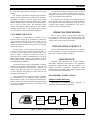
CALL DIRECTOR PATCH
In addition to normal dispatch operations, the C3
Maestro console system can be connected to Call Director
(CD) telephone equipment. This feature allows the C3
Maestro to "patch" a telephone line to a specific unit, talk
group, conventional channel or radio patch in the CEC/IMC
network. See Figure 3.
The term patch or patched, derived from phone patch,
is used to convey the CD is connected to the CEC/IMC. A
Call Director patch should not be confused with a radio
patch in which a collection of radio talk groups are
interconnected for common communications as one group.
Radio patches include standard radio patches set-up at
consoles and Causeway patches (hard patches) set-up at the
CEC/IMC Manager (MOM PC).
Call Director patch operates independently of normal
console-to-radio dispatch communications. Using the CD
interface, the dispatcher is only required to connect the CD
with the target entity (unit, group, etc.). After this operation,
no other dispatcher intervention is required until the CD
patch must be disconnected.
Audio connections between the CD and the CEC/IMC
are accomplished by the Enhanced Audio Enclosure.
Microcontroller circuits on the Audio System Board have
primary control. The console's application program running
on the PC has minimal involvement in the control of CD
patch audio switching.
CALL
DIRECTOR
Refer to the C3 Maestro Training Manual LBI-38660
for complete C3 Maestro console operating details. This
manual includes User Training Study Guide ECR-4488 and
Administrators Training Manual ECR-4489.
INSTALLATION AND SET-UP
Refer to maintenance manual LBI-39101 for complete
console installation and set-up (configuration) information.
LBI-39101 is included with this manual set.
MAINTENANCE
Enhanced Audio Enclosure and Speaker Assembly
disassembly instructions follow. Refer to the appropriate
maintenance manual included with this manual set for
detailed board-level maintenance information. These
manuals include board outline and schematic diagrams, parts
lists and circuit analysis descriptions:
DISASSEMBLY INSTRUCTIONS
Enhanced Audio Enclosure
Disassemble an Enhanced Audio
accordance with the following instructions.
C3
MAESTRO
ENHANCED
AUDIO
ENCLOSURE
Enclosure
in
CEC/IMC
Figure 3 − Basic Call Director Patch Audio Routing
13
LBI-39100
❏
Power-down the Enhanced Audio Enclosure by
turning the on/off power switch on the back of
the unit to the OFF position.
❏
Disconnect the detachable ac power cord from
the back of the Enhanced Audio Enclosure.
❏
Disconnection of other cables from the back of the
Enhanced Audio Enclosure is optional, as the top
cover may be removed with these cables connected.
❏
Lay the unit upside-down on a flat surface with the
front panel facing you.
❏
Using both index fingers, simultaneously depress
the two (2) recessed latching buttons on the sides of
the unit.
❏
With the latching buttons fully depressed, slide the
bottom of the unit approximately one (1) inch by
pushing the two (2) rubber feet nearest the front
panel away from the front panel.
❏
❏
❏
Speaker Assembly
Disassemble a Speaker Assembly in accordance with
the following instructions.
❏
If necessary, disconnect the Speaker Assembly
from the Enhanced Audio Enclosure by unplugging
the cable at the rear of the Speaker Assembly. If
tightened, the cable's DB-9 connector securing
screws may need to be loosened using a small
screwdriver.
❏
If the Speaker Assembly is a desktop version,
disassemble it to gain access to the Speaker Amp
Board as follows: Remove the four (4) screws from
the back of the case and separate the case's front
and rear sections.
Carefully return the unit to an upright position. Use
caution as the top cover and front panel assembly
may easily separate (slide) from the bottom
assembly at this time.
❏
Remove the top cover and front panel assembly
away from the bottom assembly by sliding the two
assemblies apart.
❏
14
Refer to LBI-39103 for Audio System Board
service information. Refer to LBI-39102 for I/O
Backplane Board service information. The power
supply is a non-serviceable unit; it should be
replaced in whole if a failure occurs.
If the Speaker Assembly is a rack-mount
version, removal of the assembly from the
rack-mount frame is recommended: Remove
the screws that secure the Speaker Assembly to
the rack-mount frame.
Refer to LBI-39104 for service information.
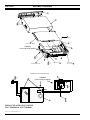
OUTLINE DIAGRAM AND PARTS LIST
8
5
6
LBI-39100
2
(NOT
SHOWN)
3
7
12
4
1
9
13
(NOT
SHOWN)
10
11
(NOT SHOWN)
NOTE:
FURNITURE NOT SUPPLIED AS PART OF SYSTEM.
C3 MAESTRO CONSOLE SYSTEM
WITH ENHANCED AUDIO ENCLOSURE
(Made from 903-0001-000 Rev. 0)
C3 MAESTRO CONSOLE SYSTEM
WITH ENHANCED AUDIO ENCLOSURE
P29/7720045009 (350A1371P1) ERICSSON - 2 DESKTOP SPKRS.
P29/7720045010 (350A1371P2) ERICSSON - 4 DESKTOP SPKRS.
ITEM
PART NUMBER
CRMC3E
Microphone, Boom.(Optional equipment
NOT included with P29/7720045009 or
P29/7720045010. Listed here for
reference only.)
7
CRMC3D
Microphone, Desk.(Optional equipment
NOT included with P29/7720045009 or
P29/7720045010. Listed here for
reference only.)
8
(See LBI-39104)
Speaker, Desktop. (Rack-mount speakers
are optional and they are not shown in
diagram; see LBI-39104.)
9
CRCN1W
Jack Box, Headset.(Optional equipment
NOT included with P29/7720045009 or
P29/7720045010. Listed here for
reference only.)
10
CRSU3C
Footswitch, Dual.(Optional equipment NOT
included with P29/7720045009 or
P29/7720045010. Listed here for
reference only.)
11
CRSU3B
Footswitch, Single (not shown in
diagram).(Optional equipment NOT
included with P29/7720045009 or
P29/7720045010. Listed here for
reference only.)
ISSUE 1
ITEM
1
1
PART NUMBER
P29/7720046000
(350A1371P11)
DESCRIPTION
Personal Computer, C3 Maestro: Includes
RS-422/485 board, DOS 6.x and C3
Maestro application software installed.
Less monitor. Not upgradeable to NT.
DESCRIPTION
6
P29/7720046001
(350A1371P12)
Personal Computer, C3 Maestro: Includes
RS-422/485 board, DOS 6.x and C3
Maestro application software installed.
Less monitor. Upgradeable to NT.
(Optional equipment NOT included with
P29/7720045009 or P29/7720045010.
Listed here for reference only.)
2
P29/7590287000
(350A1371P14 or
344A3927P37)
Monitor: 14-inch VGA.
2
P29/7590297000
(350A1371P15)
Monitor: 17-inch SVGA. (Optional
equipment NOT included with
P29/7720045009 or P29/7720045010.
Listed here for reference only.)
3
P29/7720040001
(350A1371P4)
Enhanced Audio Enclosure: Ericsson;
Includes Item 12 cable.
12
P29/5010150000
(344A1371P29)
3
P29/7720040000
(350A1371P3)
Enhanced Audio Enclosure: GE; Includes
cable Item 12 cable. (NOT included with
P29/7720045009 or P29/7720045010.
Listed here for reference only.)
Cable: 10-foot, male DB-9-to-female DB-9.
(Used for speaker and PC-to-EAE
interconnections.)
12
19B804083P2
Cable: 100-foot (Used for Console-toCEC/IMC audio interconnections).
4
P29/7590182003
(350A1371P17)
Keyboard, Dispatch: with DB-9 connector.
12
19B804083P3
Cable: 100-foot (Used for Console-toCEC/IMC RS-422 control data
interconnections).
5
CRMC3F
Microphone, Gooseneck.(Optional
equipment NOT included with
P29/7720045009 or P29/7720045010.
Listed here for reference only.)
13
P29/7590289000
(350A1371P30)
RS-422/485 Board (ESD protected).
15
LBI-39100
ASSEMBLY DIAGRAM
10
11
8
(x 1)
2
(x 5);
(not shown)
16
POWER SUPPLY
14
13 (x 2)
AUDIO SYSTEM BOARD
DANGER!
HIGH-VOLTAGE AREAS.
9
(x 4)
3
(x 4)
15
I/O BACKPLANE BOARD
12
32
30 (x 1)
37 (x 2)
REAR PANEL
PART OF ITEM 12
PART OF ITEM 15
POWER SUPPLY INTERCONNECTIONS
29
39 (x 2)
32
41 (x 4)
DANGER!
HIGH-VOLTAGE AREAS.
40 (x 7)
30
37 (x 2)
4
16
7
34
ENHANCED AUDIO ENCLOSURE
P29/7720040000 & P29/7720040001
(Made From 772-0040-XXX-HD, Rev. A)
16
PARTS LISTS
LBI-39100
ENHANCED AUDIO ENCLOSURE
P29/7720040001 (350A1371P4) ERICSSON
P29/7720040000 (350A1371P3) GE
ISSUE 1
ITEM
PART NUMBER
DESCRIPTION
1
P29/2A104C2404
Screw, machine: 4-40 x 1/4-inch, pan head
Phillips. (Qty. required = 4)
2
P29/2A106C2403
Screw, machine: 6-32 x 3/16-inch, pan
head Phillips. (Qty. required = 5)
3
P29/2A106C2404
Screw, machine: 6-32 x 1/4-inch, pan head
Phillips. (Qty. required = 9)
4
P29/2A104C2402
Screw, machine: 4-40 x 1/8-inch, pan head
Phillips. (Secures ground wire.)
5
P29/208A104020
Washer, lock: No. 4, spring, stainless
steel. (Qty. required = 4)
6
P29/208A106020
Washer, lock: No. 6, spring, stainless
steel. (Qty. required = 5)
7
P29/2080106000
Washer, lock: No. 4, internal tooth,
stainless steel. (Qty. required = 3)
8
P29/2080028000
Washer, lock: No. 6, external tooth.
9
P29/6110101000
Feet, rubber. (Qty. required = 4)
10
P29/6050030000
Panel, front: molded.
11
P29/6090546000
Enclosure, top.
12
P29/6090547000
Enclosure, bottom.
13
P29/6110100000
Guides, PCB: 6-inch (Qty. required = 2)
14
(See LBI-39103
for part number)
Board, Audio System.
15
(See LBI-39102
for part number)
Board, I/O Backplane.
16
P29/3860036000
Supply, Power: 12 Vdc @ 4.3 amp output.
17
P29/6140231001
Label, Ericsson.
17
P29/6140231000
Label, GE.
29
P29/3800133000
Connector: 2-position plug.
30
P29/3800188000
Receptacle: Fused IEC.
32
P29/3650049000
Switch, rocker: Lighted green.
34
P29/3710088000
Terminal, ring: No. 6 stud, 18-14 AWG.
35
P29/2010116000
Screw, machine: 4-40 x 1/4-inch, flat head
Phillips, stainless steel. (Qty. required = 2)
36
P29/2070073000
Nut, keeper: No. 4. (Qty. required = 2)
37
P29/3250077000
Fuse: 2.5 amp slow-blow, 5 x 20 mm. (Qty.
required = 2)
38
P29/3820021000
Cord, ac power: Right-angle IEC-320.
39
P29/3710007000
Terminal. (Qty. required = 2)
40
P29/3250003000
Terminal, quick disconnect: 0.187-inch.
(Qty. required = 7)
41
P29/1050034000
Tubing, heat shrink: 1/8-inch x 0.75-inch
(Qty. required = 4)
42
P29/5010150000
(350A1371P29)
Cable: DB-9 male/DB-9 male, 10-feet.
(Used for PC-to-EAE control data link.)
17
LBI-39100
INSTALLATION INSTRUCTIONS
ENHANCED AUDIO ENCLOSURE
(NOT INCLUDED WITH KIT. SHOWN
HERE FOR REFERENCE ONLY.)
INSTALLATION INSTRUCTIONS
1.
2.
3.
MOUNT TRAY (P29/6090561000) IN 19-INCH CABINET
OR CASE USING FOUR (4) #10-24 x 3/4 PHILLIPS PANHEAD SCREWS (P29/2040011000), FOUR (4) #10
LOCK-WASHERS (P29/2080005000), AND FOUR (4) #10
SPRING NUTS (P29/2070098000). THESE ITEMS ARE
NOT SHOWN IN DIAGRAM.
REMOVE THE FOUR (4) #6-32 PHILLIPS-HEAD
SCREWS SECURING THE RUBBER FEET TO THE
BOTTOM OF THE ENHANCED AUDIO ENCLOSURE.
RETAIN THESE SCREWS. DISCARD RUBBER FEET
UNLESS REVERSION BACK TO DESK-TOP USE MAY
BE NECESSARY IN FUTURE.
MOUNT THE ENHANCED AUDIO ENCLOSURE TO THE
TRAY USING FOUR (4) SCREWS REMOVED IN STEP
2.
RACK-MOUNT TRAY
#6-32 SCREW (4 PLACES)
(NOT INCLUDED WITH KIT. PARTS OF
ENHANCED AUDIO ENCLOSURE.)
ENHANCED AUDIO ENCLOSURE RACK-MOUNT KIT; OPTIONAL
P29/7720044000 (350A1371P19)
(772-0044-XXX-HD)
Ericsson Inc.
Private Radio Systems
Mountain View Road
Lynchburg, Virginia 24502
1-800-528-7711 (Outside U.S.A., 804-528-7711)
18
Printed in U.S.A.