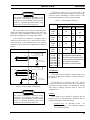
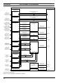
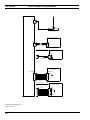
1
LBI-38985B Maintenance Manual EDACS Site Controller ericssonz LBI-38985B NOTICES REVISION HISTORY Revision Date Reason for Change - Nov 1993 Original Release. A Jan 1994 Changed numbering plan that identifies position of Application Software PROMs, and AC and DC Interconnection Diagrams. B Jan 1996 Additional information and corrections for original equipment, and new information for Guardog, DB8860-based PMU, ELI (Enhanced Local Interconnect), Multiple Channel Partition, Orion Test Unit, and MASTR III Alarms. NOTICE! This Manual covers Ericsson and General Electric products manufactured and sold by Ericsson Inc. NOTICE! Repairs to this equipment should be made only by an authorized service technician or facility designated by the supplier. Any repairs, alterations or substitution of recommended parts made by the user to this equipment not approved by the manufacturer could void the user’s authority to operate the equipment in addition to the manufacturer’s warranty. NOTICE! The software contained in this device is copyrighted by Ericsson Inc. Unpublished rights are reserved under the copyright laws of the United States. This manual is published by Ericsson Inc., without any warranty. Improvements and changes to this manual necessitated by typographical errors, inaccuracies of current information, or improvements to programs and/or equipment, may be made by Ericsson Inc., at any time and without notice. Such changes will be incorporated into new editions of this manual. No part of this manual may be reproduced or transmitted in any form or by any means, electronic or mechanical, including photocopying and recording, for any purpose, without the express written permission of Ericsson Inc. Copyright November 1993, Ericsson GE Mobile Communications Inc. 2 CONTENTS LBI-38985B TABLE OF CONTENTS PAGE SPECIFICATIONS ..................................................................................................................................... 11 INTRODUCTION....................................................................................................................................... 12 DESCRIPTION........................................................................................................................................... 13 STANDARD EQUIPMENT ................................................................................................................ 13 Cabinet .......................................................................................................................................... 13 Exhaust Fan................................................................................................................................... 13 Main AC Power Strip.................................................................................................................... 13 Auxiliary AC Power Strip ............................................................................................................. 13 EDACS Interface Panels ............................................................................................................... 13 Downlink GETC ........................................................................................................................... 13 Site Controller Computer .............................................................................................................. 15 System Manager Modem............................................................................................................... 15 DC Power Supply.......................................................................................................................... 15 Uninterruptible Power Supply (UPS)............................................................................................ 15 OPTIONAL EQUIPMENT.................................................................................................................. 15 Cabinets & Racks.......................................................................................................................... 15 230V, 50 Hz Power....................................................................................................................... 15 Power Monitor Unit (PMU) .......................................................................................................... 15 Local Telephone Interconnect....................................................................................................... 16 Redundant Downlink GETC ......................................................................................................... 16 Alarm and Control Unit (ACU)..................................................................................................... 16 Test Unit (TU)............................................................................................................................... 16 Guardog......................................................................................................................................... 17 INSTALLATION........................................................................................................................................ 18 CABINET ............................................................................................................................................ 18 PROTECTIVE GROUND ................................................................................................................... 18 AC POWER ......................................................................................................................................... 18 INTERFACE PANEL #1 ..................................................................................................................... 18 Power Sensor Module ................................................................................................................... 18 “RIC AUDIO” Modules................................................................................................................ 20 “GETC DATA” Modules.............................................................................................................. 20 “SERIAL MODULE” Module...................................................................................................... 21 INTERFACE PANEL #2 ..................................................................................................................... 21 “DOWNLINK DATA” Module.................................................................................................... 22 “PHONE LINE” Modules............................................................................................................. 22 DIRECT CONNECTIONS .................................................................................................................. 23 ELI Local Telephone Interconnect................................................................................................ 23 Alarm & Control Unit (ACU) ....................................................................................................... 24 Test Unit (TU)............................................................................................................................... 25 Guardog......................................................................................................................................... 25 System Manager............................................................................................................................ 26 INITIAL POWER-UP.......................................................................................................................... 27 3 LBI-38985B CONTENTS TABLE OF CONTENTS (Continued) PAGE FULL-FEATURED TRUNKING ............................................................................................................... 28 SITE CONTROLLER STARTUP........................................................................................................ 28 Initialization .................................................................................................................................. 28 Request for Site Database.............................................................................................................. 28 Switch Operational Mode of Site .................................................................................................. 28 GETC COMMUNICATION................................................................................................................ 28 GETC Data Links.......................................................................................................................... 28 Frame Sync Line (FSL) ................................................................................................................. 28 CONTROL CHANNEL SELECTION................................................................................................. 28 Startup ........................................................................................................................................... 29 Control Channel Failure ................................................................................................................ 29 WORKING CHANNEL ASSIGNMENTS .......................................................................................... 29 Communication Modes.................................................................................................................. 29 Call Sequence ................................................................................................................................ 29 CALL VALIDATION .......................................................................................................................... 30 CALL QUEUING................................................................................................................................. 30 DOWNLINK SELECTION ................................................................................................................. 30 SITE CONTROLLER FAILURE......................................................................................................... 31 SITE CONTROLLER RECOVERY .................................................................................................... 31 SYSTEM MANAGER ................................................................................................................................ 32 DATA LINK ........................................................................................................................................ 32 Protocol ......................................................................................................................................... 32 Baud Rate ...................................................................................................................................... 32 Data Link....................................................................................................................................... 32 PARAMETERS.................................................................................................................................... 32 ACTIVITY REPORTS......................................................................................................................... 35 ALARMS..................................................................................................................................................... 36 ALARM DETECTION ........................................................................................................................ 36 Site Controller ............................................................................................................................... 36 Power Monitor Unit....................................................................................................................... 36 Alarm & Control Unit.................................................................................................................... 36 Test Unit........................................................................................................................................ 36 Station GETC ................................................................................................................................ 37 Downlink GETC............................................................................................................................ 37 ALARM MANAGEMENT .................................................................................................................. 38 Channel Failure/Recovery ............................................................................................................. 38 Polling Failure/Recovery............................................................................................................... 38 Fault Tolerance Threshold............................................................................................................. 39 ACU Display Panel ....................................................................................................................... 40 CRITICAL FAULT ALARMS............................................................................................................. 40 Description .................................................................................................................................... 40 System Requirements .................................................................................................................... 40 Compatibility with PMU Option ................................................................................................... 40 Channel Failure / Recovery ........................................................................................................... 41 4 CONTENTS LBI-38985B TABLE OF CONTENTS (Continued) PAGE ALARM & CONTROL UNIT .................................................................................................................... 42 DESCRIPTION.................................................................................................................................... 42 INPUTS................................................................................................................................................ 42 OUTPUTS............................................................................................................................................ 42 PARAMETERS ................................................................................................................................... 42 Alarm Inputs.................................................................................................................................. 42 Control Outputs............................................................................................................................. 42 MESSAGING ...................................................................................................................................... 42 OPERATION ....................................................................................................................................... 42 Startup ........................................................................................................................................... 42 Alarm Inputs.................................................................................................................................. 43 Control Outputs............................................................................................................................. 43 ACU Front Panel Alarm Display .................................................................................................. 43 System Manager Alarm Display.................................................................................................... 43 TEST UNIT................................................................................................................................................. 44 DESCRIPTION.................................................................................................................................... 44 RANGR Test Unit......................................................................................................................... 44 MDX Test Unit ............................................................................................................................. 44 Orion Test Unit ............................................................................................................................. 44 PARAMETERS ................................................................................................................................... 44 MESSAGING ...................................................................................................................................... 44 OPERATION ....................................................................................................................................... 45 Modes of Operation ...................................................................................................................... 45 Background Test Calls .................................................................................................................. 45 Recovery Test Calls ...................................................................................................................... 45 POWER MONITOR UNIT......................................................................................................................... 47 DB8860-BASED PMU ........................................................................................................................ 47 Description.................................................................................................................................... 47 System Requirements .................................................................................................................... 47 Parameters..................................................................................................................................... 47 DB8843-BASED PMU ........................................................................................................................ 48 Description.................................................................................................................................... 48 System Requirements .................................................................................................................... 48 Parameters..................................................................................................................................... 48 MESSAGING ...................................................................................................................................... 49 OPERATION ....................................................................................................................................... 50 Power Sensors ............................................................................................................................... 50 PMU Activity ................................................................................................................................ 50 Site Controller Activity ................................................................................................................. 50 5 LBI-38985B CONTENTS TABLE OF CONTENTS (Continued) PAGE GUARDOG ................................................................................................................................................. 52 DESCRIPTION .................................................................................................................................... 52 INPUTS................................................................................................................................................ 52 OUTPUTS............................................................................................................................................ 52 OPERATION ....................................................................................................................................... 52 Automatic Reset Cycle .................................................................................................................. 52 External Reset Disable Cycle ........................................................................................................ 53 LOCAL INTERCONNECT ........................................................................................................................ 54 GENERAL ........................................................................................................................................... 54 Equipment Versions ...................................................................................................................... 54 Parameters ..................................................................................................................................... 54 Interconnect Timing Settings......................................................................................................... 57 Toll Call Restrictions..................................................................................................................... 59 Dedicated Lines............................................................................................................................. 59 Interconnect Rotary Definition ...................................................................................................... 59 RIC / LIC INTERCONNECT .............................................................................................................. 59 Description .................................................................................................................................... 59 Additional Parameter..................................................................................................................... 60 ELI INTERCONNECT ........................................................................................................................ 60 Description .................................................................................................................................... 60 System Requirements .................................................................................................................... 60 Additional Parameter..................................................................................................................... 60 OPERATION (RIC/LIC & ELI) .......................................................................................................... 60 Definitions ..................................................................................................................................... 60 Telephone-Originated Call ............................................................................................................ 61 Radio-Originated Call ................................................................................................................... 63 MULTIPLE CHANNEL PARTITION........................................................................................................ 66 DESCRIPTION .................................................................................................................................... 66 COMPATIBILITY............................................................................................................................... 66 Channel Test.................................................................................................................................. 66 Test Calls....................................................................................................................................... 66 Mixing MCP Enabled & Disabled Systems................................................................................... 66 SYSTEM REQUIREMENTS............................................................................................................... 66 System Manager ............................................................................................................................ 66 Site Controller ............................................................................................................................... 66 PARAMETERS.................................................................................................................................... 66 MCP Channel Data........................................................................................................................ 67 MCP ID Data................................................................................................................................. 67 PARTITION PLANNING.................................................................................................................... 67 Overview ....................................................................................................................................... 67 Channel Partitions ......................................................................................................................... 67 Active & Allowed Control Channels............................................................................................. 68 IDs Subject to Partitioning ............................................................................................................ 69 Primary Partition ........................................................................................................................... 70 Backup Partitions .......................................................................................................................... 70 EXAMPLES ......................................................................................................................................... 71 Single-Site System with One Partition........................................................................................... 71 Single-Site System with Multiple Partitions .................................................................................. 71 6 CONTENTS LBI-38985B TABLE OF CONTENTS (Continued) PAGE INITIAL MCP DATA.......................................................................................................................... 72 MCP Channel Data ....................................................................................................................... 72 MCP ID Data ................................................................................................................................ 72 MCP CHANNEL DATA CONFIGURATION.................................................................................... 72 MC Partitioning Enabled............................................................................................................... 72 Allowed CC................................................................................................................................... 73 MC Partition.................................................................................................................................. 73 Database Uploads.......................................................................................................................... 73 Temporary Uploads....................................................................................................................... 73 MCP ID DATA CONFIGURATION .................................................................................................. 74 MCP Availability .......................................................................................................................... 74 ID Subject to Partitioning.............................................................................................................. 74 Primary Partition ........................................................................................................................... 74 Backup Partitions .......................................................................................................................... 74 Database Uploads.......................................................................................................................... 75 Temporary Uploads....................................................................................................................... 76 OPERATION ....................................................................................................................................... 76 MCP Disabled Systems................................................................................................................. 76 Which Partition Is Searched.......................................................................................................... 76 Conditions for Searching Backup Partitions ................................................................................. 76 Primary Level of Search................................................................................................................ 76 First Backup Level of Search ........................................................................................................ 79 Second Backup Level of Search.................................................................................................... 80 Third Backup Level of Search ...................................................................................................... 81 Call Queuing ................................................................................................................................. 82 Call Denial .................................................................................................................................... 82 Examples of Non-Emergency Individual Calls ............................................................................. 83 Examples of Non-Emergency Group Calls ................................................................................... 84 Examples of Emergency Group Calls ........................................................................................... 84 MAINTENANCE........................................................................................................................................ 85 SOFTWARE REPLACEMENT .......................................................................................................... 85 PROM Card Removal ................................................................................................................... 85 PROM Replacement...................................................................................................................... 86 CABINET VENTILATION................................................................................................................. 87 POWER SENSOR CALIBRATION.................................................................................................... 87 TROUBLESHOOTING .............................................................................................................................. 88 GENERAL ........................................................................................................................................... 88 RECOVERY FROM FAILSOFT......................................................................................................... 88 SITE CONTROLLER RESET............................................................................................................. 88 TROUBLESHOOTING GUIDES ....................................................................................................... 88 PARTS LIST ............................................................................................................................................... 93 GLOSSARY................................................................................................................................................ 94 7 LBI-38985B CONTENTS TABLE OF CONTENTS (Continued) PAGE APPENDIX A DB8843-BASED PMU .......................................................................................................114 INTRODUCTION................................................................................................................................114 DUPLEXER APPLICATION ..............................................................................................................114 INTERCONNECTIONS ......................................................................................................................114 POWER SENSOR CALIBRATION ....................................................................................................114 Unidirectional Power Sensors .......................................................................................................114 Bi-directional Power Sensors ........................................................................................................115 DIP SWITCHES...................................................................................................................................117 PARAMETERS....................................................................................................................................117 Channel Fault Tolerance Threshold ..............................................................................................118 Channel PMU Enable ....................................................................................................................118 Site PMU Enable...........................................................................................................................118 PMU Low Power Alarm Threshold...............................................................................................118 MIN IPF ........................................................................................................................................118 MAX SWR....................................................................................................................................118 CHNL DES ...................................................................................................................................118 PROGRAMMING................................................................................................................................118 Memory Clear................................................................................................................................119 CHNL DES (Antenna Mapping) ...................................................................................................119 MIN IPF ........................................................................................................................................119 MAX SWR....................................................................................................................................119 TROUBLESHOOTING .......................................................................................................................120 Site Controller Personality ............................................................................................................120 Speed Up Clearing Alarm..............................................................................................................120 Three Coinciding Alarms ..............................................................................................................120 Fault Tolerance Threshold.............................................................................................................120 Miscellaneous Symptoms ..............................................................................................................120 APPENDIX B - MCP ASSISTANTS .........................................................................................................123 MULTIPLE CHANNEL PARTITION (MCP) FEATURE CHECKLIST...........................................123 1. System Requirements ................................................................................................................123 2. Running the System with Default MCP Data ............................................................................123 3. Creating Partition Plan ..............................................................................................................123 4. Implementing Partition Plan ......................................................................................................124 5. Partition Plan Operational Verification .....................................................................................128 6. Partition Plan Updates ...............................................................................................................128 7. Partition Plan Deactivation........................................................................................................128 MULTIPLE CHANNEL PARTITION (MCP) PLANNING WORKSHEETS ...................................129 MCP Template: Channel Data......................................................................................................129 MCP Template: ID Data...............................................................................................................130 MCP Template: ID Data...............................................................................................................131 S 8 CONTENTS LBI-38985B FIGURES & TABLES PAGE Figure 1 - Location of Standard and Optional Equipment in 69-Inch Cabinet ............................................ 14 Figure 2 - External Connections to EDACS Interface Panel #1 .................................................................. 19 Figure 3 - External Connections to EDACS Interface Panel #2 .................................................................. 21 Figure 4 - Direct Connections (Rear View)................................................................................................. 23 Figure 5 - Alarm Input Configurations ........................................................................................................ 24 Figure 6 - Control Output Configurations ................................................................................................... 25 Figure 7 - Back View of Modem / Reset Unit Chassis ................................................................................ 26 Figure 8 - Inside View of Reset Unit........................................................................................................... 26 Figure 9 - System Manager Data Link without Modems ............................................................................. 26 Figure 10 - Location of Fastener Screws ..................................................................................................... 85 Figure 11 - PROM Card Location In Later VAX ........................................................................................ 85 Figure 12 - Fastener Screw Location In Earlier VAX ................................................................................. 85 Figure 13 - PROM Card Location In Earlier VAX ..................................................................................... 86 Figure 14 - PROM Card Location for Top Entry ........................................................................................ 86 Figure 15 - Location of PROMs on PROM Card ........................................................................................ 86 Figure 16 - Application Software PROM Label .......................................................................................... 87 Figure 17 - Personality PROM Label .......................................................................................................... 87 Table 1 - Downlink Connection Pin Identification...................................................................................... Table 2 - Telephone Line Connection Pin Identification............................................................................. Table 3 - Alarm Input Connections ............................................................................................................. Table 4 - Control Output Connections......................................................................................................... Table 5 - Local Interconnect Timing Parameter Adjustments For Release 7 .............................................. Table 6 - Which Partition Is Searched......................................................................................................... Table 7 - When Is Backup Partition Searched............................................................................................. Table 8 - Example 1 .................................................................................................................................... Table 9 - Example 2 .................................................................................................................................... Table 10 - Example 3 .................................................................................................................................. Table 11 - Example 4 .................................................................................................................................. Table 12 - Example 5 .................................................................................................................................. Table 13 - Example 6 .................................................................................................................................. Table 14 - Example 7 .................................................................................................................................. Table 15 - Example 8 .................................................................................................................................. Table 16 - Multiple Channel Partition (MCP) Troubleshooting Guide ....................................................... 22 22 24 25 58 77 78 83 83 83 83 84 84 84 84 89 9 LBI-38985B CONTENTS INTERCONNECTION DIAGRAMS Interconnection Diagram 1 Interconnection Diagram 2 Interconnection Diagram 3 Interconnection Diagram 4 Interconnection Diagram 5 Interconnection Diagram 6 Interconnection Diagram 7 Interconnection Diagram 8 Interconnection Diagram 9 Interconnection Diagram 10 Interconnection Diagram 11 Interconnection Diagram 12 Interconnection Diagram 13 Interconnection Diagram 14 Interconnection Diagram 15 Interconnection Diagram 16 Interconnection Diagram 17 Interconnection Diagram 18 10 PAGE Latest Overall Configuration (3 or 4 Repeaters / Cabinet)............................ 97 Earlier Overall Configuration (2 Repeaters / Cabinet) .................................. 98 Earlier Overall Configuration (3 Repeaters / Cabinet) .................................. 99 Latest System Manager Data Link (with ZyXEL Modem)............................100 Earlier System Manager Data Link (with U.S. Robotics Modem) ................100 Latest Station GETC Data Links (3 or 4 Repeaters / Cabinet)......................101 Earlier Station GETC Data Links (2 Repeaters / Cabinet) ............................102 Downlink GETCs..........................................................................................103 RIC/LIC Local Telephone Interconnect (2 Repeaters / Cabinet) ..................104 RIC/LIC Local Telephone Interconnect (3 Repeaters / Cabinet) ..................105 Latest DB8860-Based Power Monitor Unit (No Keypad on Front)..............106 Earlier DB8843-Based PMU (Keypad on Front) ..........................................107 Alarm and Control Unit.................................................................................108 Guardog.........................................................................................................109 Orion Test Unit .............................................................................................110 120 V, 60 Hz AC Power ...............................................................................111 230 V, 50/60 Hz AC Power ..........................................................................112 12 VDC Power Distribution..........................................................................113 SPECIFICATIONS LBI-38985 SPECIFICATIONS Environmental: Storage: Altitude ......................................................... 0 to 4876.8 m (0 to 16,000 ft) Temperature .................................................. -40° to 66° C (-40° to 150.8° F) at sea level Relative Humidity ......................................... 0 to 95%, non-condensing Operation: Altitude ......................................................... 0 to 2438.4 m (0 to 8,000 ft) Temperature .................................................. 5° to 50° C (41° to 122° F) at sea level Relative Humidity ......................................... 10 to 95%, non-condensing Mechanical: Dimensions: 69" Cabinet ................................................... 69" H x 23" W x 21" D 83" Cabinet ................................................... 83" H x 23" W x 21" D 86" Open Rack .............................................. 86" H x 23" W x 12.00" D Weight: 69" Cabinet ................................................... 160 to 200 lb. 83" Cabinet ................................................... 170 to 210 lb. 86" Open Rack .............................................. 100 to 140 lb. Input Power: Voltage ............................................................... 120 VAC ± 20% or 230 VAC + 10% to − 15% Frequency............................................................. 60 Hz ± 2% 50 Hz ± 2% External Breaker Size........................................... 20 A 10 A 11 LBI-38985 DESCRIPTION INTRODUCTION EDACS, an acronym which stands for Enhanced Digital Access Communications System, is a registered trademark of Ericsson Inc. EDACS is used in the names of the digitally-trunked radio systems (and their major components) sold by Ericsson Inc. to differentiate them from conventional systems and equipment, also available. An EDACS Repeater consists of a conventional MASTR III repeater and a Station GETC. Three or more EDACS Repeaters connected together at one location makes a Basic EDACS system. In a Basic EDACS system, one EDACS Repeater serves as the Control Channel, and its Station GETC is referred to as the Control Channel GETC. All other EDACS Repeaters serve as Working Channels, and their Station GETCs are referred to as Working Channel GETCs. In a Basic EDACS system, the Control Channel GETC supervises the trunking of the Working Channels. Trunking under the supervision of the Control Channel GETC is referred to as Failsoft Trunking. LBI 39074 - EDACS MASTR III Repeater (System Installation) LBI-38984 - System Manager (User’s Guide) LBI-38812 - EDACS Interface Panel LBI-39128 - DB8860 Power Monitor Unit LBI-38513 - EDACS Local Telephone Interconnect (RIC/LIC Interconnect) LBI-39076 - EDACS Enhanced Local Interconnect (ELI Interconnect) LBI-39077 - EDACS Enhanced Local Interconnect, GTI Configurator Software (ELI Interconnect) LBI-38896 - Downlink GETC (Configuration Manual) LBI-38894 - GETC Shelf (Includes LBI-38822 for GETC 1e Turbo Board) With the addition of an EDACS Site Controller, the Site Controller (computer) takes over the supervision of the trunking and adds an expanded set of features, while retaining the ability to fall back to Failsoft Trunking in the event the Site Controller should ever fail. Trunking under the supervision of the Site Controller is referred to as FullFeatured Trunking. LBI-33031 - Downlink/System Manager Modem Except where noted otherwise, this instruction manual describes the latest standard and optional EDACS Site Controller equipment (hardware and software) supplied from the factory. Occasionally information is provided for earlier equipment. For additional information about the equipment, see one or more of the following instruction manuals: LBI-39004 - Guardog 12 LBI-31939 - Test and Alarm Unit (Includes the Alarm and Control Unit, and the RANGR Test Unit) LBI-38980 - 900 MHz MDX Test Unit LBI-39167 - Orion Test Unit LBI-38550 - Station Power Supply LBI-4841 - 120 VAC Outlet Strip LBI-4842 - Cabinet Top Fan DESCRIPTION DESCRIPTION The EDACS Site Controller is made up of the Site Controller cabinet, the Site Controller computer, and all of the standard and optional supporting equipment that gets mounted in the Site Controller cabinet. The standard arrangement for a fully-equipped EDACS Site Controller is shown in Figure 1. The actual arrangement may vary somewhat, depending upon which options or special customer requirements are supplied. Blank panels are provided in place of non-supplied optional front-mounted equipment. The Auxiliary AC Power Strip is used in place of the AC Relay Panel when the Guardog option is not supplied. The 230V, 50Hz version of the Main AC Power Strip is mounted in a different position than the 120V, 60Hz version. For more information, see Interconnection Diagram 16 or Interconnection Diagram 17 at the end of this manual. The EDACS Site Controller supports up to 20 channels for a Level 1 EDACS system, or up to 24 channels for a Voted (non-Simulcast) or Simulcast (Voted or non-Voted) system. In a Level 1 system, the EDACS Site Controller is located at the site with the EDACS Repeaters. In a Voted (non-Simulcast) system, the EDACS Site Controller is located at the Main Site. In a Simulcast system, the EDACS Site Controller is located at the Control Point. STANDARD EQUIPMENT The standard EDACS Site Controller consists of the following standard equipment: LBI-38985 Cabinet The 69-inch enclosed cabinet provides physical, electrical, and dust protection for the Site Controller equipment. Exhaust Fan The 120V AC exhaust fan provides additional air flow for cooling the Site Controller equipment. For connections to the Exhaust Fan, see Interconnection Diagram 16 at the end of this manual. Main AC Power Strip The 6-outlet 120V main AC power strip provides the 15-foot AC power cord for the Site Controller cabinet, and AC outlets for the exhaust fan, uninterruptible power supply, and DC power supply. For connections to the Main AC Power Strip, see Interconnection Diagram 16 at the end of this manual. Auxiliary AC Power Strip The 2-outlet 120V auxiliary AC power strip plugs into the uninterruptible power supply, and provides AC outlets for the Site Controller computer and the modem for the data link to the System Manager. For connections to the Auxiliary AC Power Strip, see Interconnection Diagram 16 at the end of this manual. EDACS Interface Panels • Cabinet • Exhaust Fan • Main AC Power Strip • Auxiliary AC Power Strip • EDACS Interface Panels • Downlink GETC • Site Controller • System Manager Modem • DC Power Supply • Uninterruptible Power Supply Two EDACS Interface Panels provide the connection point between circuits outside the cabinet and circuits inside the cabinet. For connections to the EDACS Interface Panels, see Interconnection Diagram 1 at the end of this manual. Downlink GETC The Downlink GETC provides the interface at the system end of the data link (Downlink) between the system and the network. During Failsoft Trunking, it provides the interface between the Station GETCs and the network. During Full-Featured Trunking, it provides the interface between the Site Controller computer and the network. For connections to the Downlink GETC, see Interconnection Diagram 8 at the end of this manual. 13 LBI-38985B DESCRIPTION BACK-MOUNTED EQUIPMENT FRONT-MOUNTED EQUIPMENT 36 RU EDACS Interface Panel #1 34 RU 3-RU Blank Panel 32 RU DB8860-Based PMU EDACS Interface Panel #2 30 RU 2-RU Blank Panel 28 RU 2-RU Blank Panel 26 RU L1L2L3L4L5L6L7 Downlink GETC L1L2L3L4L5L6L7 Redundant Downlink GETC 24 RU 1-RU Blank Panel 22 RU Site Controller 20 RU 1-RU Blank Panel 18 RU 16 RU Alarm & Control Unit 14 RU AC Relay Panel (Guardog) 12 RU Orion TU 10 RU Reset Unit & Modem 1-RU Blank Panel 8 RU 1-RU Blank Panel 6 RU DC Power Supply 4 RU 2 RU 0 RU Figure 1 - Location of Standard and Optional Equipment in 69-Inch Cabinet 14 Uninterruptible Power Supply DESCRIPTION LBI-38985B Site Controller Computer • Power Monitor Unit (PMU) The Site Controller is a 32-port DEC computer with application software to provide system-level supervision for the EDACS equipment in a single or multisite EDACS system. Earlier models are referred to as PDP-11 models. Later models are referred to as VAX models. Earlier PDP11 models and later VAX models (except the current VAX model) are identified by the use of EMULEX or DILOG panels as connection points to the Site Controller. The current VAX model is identified by the 8-pin modular connectors mounted directly in the back panel of the Site Controller. For connections to the Site Controller, see Interconnection Diagram 1 at the end of this manual. • Local Telephone Interconnect • Redundant Downlink GETC • Alarm and Control Unit (ACU) • Test Unit (TU) • Guardog System Manager Modem The modem for the data link to the System Manager provides the interface at the Site Controller end when a voice-frequency data link is used between the Site Controller and the System Manager. For connections to the System Manager, see Interconnection Diagram 4 at the end of this manual. Cabinets & Racks The EDACS Site Controller equipment may also be mounted in one of the following optional cabinets or open racks: 83” standard-depth cabinet 83” extra-deep cabinet 86” standard-depth open rack 86” extra-deep open rack DC Power Supply The DC Power Supply provides regulated +13.8 VDC for the standard Downlink GETC and the optional Power Monitor Unit, Redundant Downlink GETC, Alarm and Control Unit, Test Unit, and Guardog (Reset Unit and AC Relay Panel). For connections to the DC Power Supply, see Interconnection Diagram 18 at the end of this manual. Uninterruptible Power Supply (UPS) The Uninterruptible Power Supply (UPS) provides an uninterrupted, filtered, and regulated 120V, 60Hz output over a wide range of AC line input voltages (including short power outages of up to ten minutes) for the Site Controller computer and the modem for the data link to the System Manager. For connections to the Uninterruptible Power Supply, see Interconnection Diagram 16 at the end of this manual. OPTIONAL EQUIPMENT EDACS Site Controller options may add equipment to, or substitute equipment for, the standard equipment. The EDACS Site Controller may therefore include some of the following optional equipment: • Cabinets & Racks • 230V, 50 Hz Power 96” open rack. 230V, 50 Hz Power The 230V, 50 Hz power option substitutes 230V, 50 Hz versions for the following standard equipment: cabinet fan, 6-outlet main AC power strip, 2-outlet auxiliary AC power strip, modem for the data link to the System Manager, DC power supply, and uninterruptible power supply. For connections to the 230V, 50 Hz equipment, see Interconnection Diagram 17 at the end of this manual. Power Monitor Unit (PMU) The DB8860-based PMU option replaces the previously used DB8843-Based PMU option. Both are used for Level 1 system applications, but not for Voted system or Simulcast system applications. DB8860-Based PMU The DB8860-based PMU option provides a transmitter alarm when a transmitter’s output power drops below a minimum level, or rises above a maximum level. The PMU also provides an antenna alarm when an antenna’s input SWR rises above a maximum value. Up to 20 transmitters and 2 antennas can be monitored. The PMU operates under the direction of, and reports alarms to, the Site Controller computer. 15 LBI-38985B DESCRIPTION The DB8860-based PMU option requires a PMU mounted in the Site Controller cabinet, one transmitter power sensor installed at the output of each transmitter, and one antenna power sensor installed at the input of the coax to each transmit antenna. The transmitter power sensors are mounted in the EDACS Repeater cabinets; the antenna power sensors in the RF Equipment cabinets. For connections to the DB8860-based PMU, see Interconnection Diagram 11 at the end of this manual. DB8843-Based PMU The DB8843-based PMU option provides a transmitter alarm when a transmitter’s output power drops below a minimum level. The PMU also provides an antenna alarm when the antenna’s input SWR rises above a maximum value. Up to 20 transmitters and 2 antennas can be monitored. The PMU operates under the direction of, and reports alarms to, the Site Controller computer. The DB8843-based PMU option requires a PMU mounted in the Site Controller cabinet, one transmitter power sensor installed at the output of each transmitter, and one antenna power sensor installed at the input of the coax to each transmit antenna. The transmitter power sensors are mounted in the EDACS Repeater cabinets; the antenna power sensor(s) in the RF Equipment cabinet(s). For connections to the DB8843-based PMU, see Interconnection Diagram 12 at the end of this manual. Local Telephone Interconnect The Enhanced Local Interconnect (ELI) option replaces the previously used RIC/LIC Local Telephone Interconnect option. Enhanced Local Interconnect (ELI) The Enhanced Local Interconnect (ELI) option provides the connection of authorized radios to a local telephone system, for telephone or radio initiated calls, without dispatcher assistance. ELI operates under the direction of the Site Controller computer. The ELI option requires no hardware installation in the Site Controller cabinet, but does require one Global Telephone Interconnect (GTI) Unit installed with each radio channel to be used for local telephone interconnect calls. Each GTI Unit can be connected to one telephone line, which will be shared with all other GTI Units. For connections to the ELI Local Telephone Interconnect, see Interconnection Diagram 1 at the end of this manual. 16 RIC/LIC Local Telephone Interconnect The RIC/LIC Local Telephone Interconnect option provides the connection of authorized radios to a local telephone system, for telephone or radio initiated calls, without dispatcher assistance. The RIC/LIC Local Telephone Interconnect operates under the direction of the Site Controller computer. The RIC/LIC Local Telephone Interconnect option requires a LIX/LIC shelf mounted in the Site Controller cabinet and a RIC shelf installed with each radio channel to be used for local telephone interconnect calls. For connections to the RIC/LIC Local Telephone Interconnect, see Interconnection Diagram 9 or Interconnection Diagram 10 at the end of this manual. Redundant Downlink GETC The Redundant Downlink GETC option provides a backup for the Downlink GETC. The Redundant Downlink GETC provides the interface at the system end of the redundant data link (Redundant Downlink) between the system and the network. The Redundant Downlink GETC option requires the installation of a second Downlink GETC in the Site Controller cabinet (and the availability of a second Downlink to the CEC or IMC). For connections to the Redundant Downlink GETC, see Interconnection Diagram 8 at the end of this manual. Alarm and Control Unit (ACU) The Alarm and Control Unit (ACU) option provides alarm inputs for up to 32 customer-supplied alarms, normally-open and normally-closed control relay outputs for up to 8 customer-supplied devices, and a display panel indicating the status of up to 56 alarm or control parameters. The ACU also provides the data interface between the RANGR or MDX Test Unit and the Site Controller. The Alarm and Control Unit (ACU) can be operated with or without the Test Unit (TU). The ACU operates under the direction of the Site Controller computer. For connections to the ACU, see Interconnection Diagram 13 at the end of this manual. Test Unit (TU) The Orion Test Unit (TU) replaces the previously used RANGR and 900 MHz MDX Test Units. DESCRIPTION LBI-38985B Orion 900 MHz MDX The Orion TU option provides a means of testing the radio channels by monitoring the messages on the Control Channel and making mobile-simulated test calls. The TU operates under the direction of the Site Controller computer. The 900 MHz MDX TU option provides a means of testing the radio channels by monitoring the messages on the Control Channel and making mobile-simulated test calls. The TU operates under the direction of the Site Controller computer. The Orion TU option requires the installation of the Orion TU shelf (with radio) in the Site Controller cabinet. For connections to the Orion TU, see Interconnection Diagram 15 at the end of this manual. RANGR The RANGR TU option provides a means of testing the radio channels by monitoring the messages on the Control Channel and making mobile-simulated test calls. The TU operates under the direction of the Site Controller computer. The RANGR TU option requires the presence of the Alarm and Control Unit (ACU) option and the installation of the RANGR TU radio in the shelf provided by the ACU option. For connections to the RANGR TU, see Interconnection Diagram 2 at the end of this manual. The 900 MHz MDX TU option requires the presence of the Alarm and Control Unit (ACU) option and the installation of the TU radio in the shelf provided by that option. For connections to the 900 MHz MDX TU, see Interconnection Diagram 2 at the end of this manual. Guardog The Guardog option provides automatic local and manual remote resetting of the Station GETCs, System Manager Modem, and Site Controller computer. The Guardog can operate automatically (by looking at the local Failsoft Status line from the Station GETCs) or manually (by receiving instructions from a system administrator at a remote location). The Guardog option requires the installation of an AC Relay Panel and a Reset Unit in the Site Controller cabinet. For connections to the Guardog, see Interconnection Diagram 14 at the end of this manual. 17 LBI-38985B INSTALLATION INSTALLATION Each step of the installation consists of one or more information paragraphs followed by one or more action items (identified by the ❏ symbol so it can be checked off when completed). Skip steps for equipment not supplied. CABINET AC POWER The AC power for the Site Controller cabinet must be supplied through a separate circuit breaker. Use a 20-amp circuit breaker for 120 V, 60 HZ, or a 10-amp circuit breaker for 230 V, 50 Hz. The outlet for this circuit must be placed within reach of the Site Controller cabinet’s power cord. The cabinet or open rack has four holes in the bottom for 1/2-inch bolts or lag screws to fasten the cabinet or open rack directly to the floor, or to a raised platform (which is itself secured directly to the floor). An open rack also comes with two holes in each side (one near the top; one near the bottom) for 3/8-inch bolts for securing the rack to another rack on either side. The Site Controller cabinet is equipped with an AC power cord terminated with a NEMA 5-15 type plug for 120V, 60 Hz, or a CEE 7/7 type plug for 230V, 50 Hz. The AC power cord may be routed through the top or bottom of the cabinet. The AC power cord is approximately 15 feet long from the point where it is fastened to a power strip near the bottom of the cabinet. Therefore, routing the cord through the top of the cabinet will make it appear shorter by the approximate height of the cabinet. ❏ Secure the Site Controller cabinet (or open rack) to the floor or the raised platform using four 1/2-inch bolts or lag screws. If the EDACS Site Controller is mounted in an open rack, also fasten the rack to any adjoining rack using two 3/8-inch bolts. ❏ Turn off the AC circuit breaker for the EDACS Site Controller cabinet. Plug the EDACS Site Controller’s AC power cord into the AC outlet provided for the Site Controller cabinet. Do not turn the AC circuit breaker on. PROTECTIVE GROUND INTERFACE PANEL #1 A protective ground wire must connect the Site Controller cabinet to the same single-point ground that is used by all equipment in the room. Use annealed copper wire with a cross section no smaller than that of #2 AWG wire and no longer than 25 feet. Solid wire is better than stranded wire. Use as straight and direct a route as practical. If bends are unavoidable, they should have no less than a 12inch bending radius. Do not run the wire through metal conduit. The EDACS Site Controller is equipped with two EDACS Interface Panels mounted in the back of the cabinet near the top. The upper panel is referred to as EDACS Interface Panel #1 (part number 19D904009G12) and is shown in Figure 2. The Site Controller cabinet is equipped with a copper ground bus running vertically along the left side rail, as viewed from the back of the cabinet. The protective ground wire can be run through the top of the cabinet and connected to the upper end of this ground bus, or run through the bottom of the cabinet and connected to the bottom end of this ground bus. ❏ Connect a protective ground wire from the ground bus in the Site Controller cabinet, to the single-point ground that is used by all equipment in the room. 18 Power Sensor Module If the EDACS Site Controller is equipped with a Power Monitor Unit, the upper interface panel is equipped with a Power Sensor module. The Power Sensor module provides the connection points between the transmitter power sensor circuits from the repeater cabinets and the Power Monitor Unit in the Site Controller cabinet. The Power Sensor module also provides the connection points for the antenna power sensor circuits between each antenna power sensor in an RF cabinet and the Power Monitor Unit in the Site Controller cabinet. The 19C852632G1 Power Sensor module is used with the present DB8860-based Power Monitor Unit as shown in Interconnection Diagram 11 at the end of this manual. The earlier 19C852213G1 Power Sensor module was used with the earlier DB8843-based Power Monitor Unit as shown in Interconnection Diagram 12 at the end of this manual. INSTALLATION LBI-38985B A: Connection for daisy chain to channels 1-10 (2 repeaters / cabinet), or to channels 1-12 (3 or 4 repeaters / cabinet). Plug with shorting jumpers (in J1 of Power Sensor module) must be moved to the end of daisy chain. B: Connection for daisy chain to channels 11-20 (2 repeaters / cabinet), or to channels 13-20 (3 or 4 repeaters / cabinet). Plug with shorting jumpers (in J2 of Power Sensor module) must be moved to the end of daisy chain. C: Connection for antenna sensor circuits. Figure 2 - External Connections to EDACS Interface Panel #1 Transmitter Circuits A transmitter power sensor circuit consists of a power sensor at the output of a transmitter, the cable connecting it to the Power Sensor module in the repeater cabinet, and a series of daisy-chained cables between the Power Sensor modules in neighboring repeater cabinets and finally the Site Controller cabinet. The transmitter power sensor circuits for channels 1 through 12 are carried by one daisy chain of cables. The transmitter power sensor circuits for channels 10 through 20 are carried by another daisy chain of cables. The transmitter power sensor circuits for channels 11 and 12 are included in both daisy chains to support configurations of either 2, 3, or4 channels per cabinet. NOTE All unused transmitter power sensor circuits must be grounded (jumper present on jumper board). The power sensor circuits for channels 11 and 12 each have two jumpers (one on each jumper board). Both jumpers must be removed if a power sensor is connected to one of these circuits. All unused transmitter power sensor circuits must be grounded. One jumper board, with grounding jumpers, is provided for installation at the end of each of the two possible daisy chains. When no second daisy chain is used the second jumper board is installed in the Power Sensor module in the Site Controller cabinet. These 19C852379G1 jumper boards are usually found wrapped in plastic and taped to the top of the Site Controller computer. ❏ Connect a 25-pair cable from J1 on the Power Sensor module in the Site Controller cabinet, to J14 on the Power Sensor module in the first repeater cabinet of the first group of channels (repeater cabinet containing channel 1). ❏ Follow the string of 25-pair cables connecting J15 on one Power Sensor module, to J14 on the next until you reach an empty J15. Plug the first 19C852379G1 jumper board into this empty J15. ❏ Remove the jumper for each channel which is equipped with a power sensor (see interconnection diagram at the end of this manual). If channel 11 or 12 is equipped with a power sensor, that jumper must be removed from both jumper boards. 19 LBI-38985B INSTALLATION ❏ power. If the antenna power sensor circuits for antenna #2 are not connected to a power sensor, they must be grounded (shorted). To ground the unused power sensor circuits for antenna #2, make up two shorted phono jacks and plug the two unused phono plugs into them. ❏ “RIC AUDIO” Modules Connect a 25-pair cable from J2 on the Power Sensor module in the Site Controller cabinet, to J14 on the Power Sensor module in the first repeater cabinet of the second group of channels (repeater cabinet containing channel 11 or 13). Follow the string of 25-pair cables connecting J15 on one Power Sensor module, to J14 on the next until you reach an empty J15. Plug the second 19C852379G1 jumper board into this empty J15 (or into J2 on the Power Sensor module in the Site Controller cabinet if there was no second group of channels). ❏ Remove the jumper for each channel which is equipped with a power sensor (see interconnection diagram at the end of this manual). If channel 11 or 12 is equipped with a power sensor, that jumper must be removed from both jumper boards. Antenna Circuits An antenna power sensor circuit consists of a power sensor at the input to a transmit antenna in that antenna’s RF cabinet and the cable connecting it directly to the Power Sensor module in the Site Controller cabinet. Both forward and reflected antenna power sensor circuits for each of two possible antennas share the same connector on the Power Sensor module in the Site Controller cabinet. All unused antenna power sensor circuits must be grounded. No jumper board is provided for this purpose, as was the case for the transmitter power sensor circuits. NOTE All unused antenna power sensor circuits must be grounded. ❏ Plug the 19C852677P3 antenna power sensor cable into J9 on the Power Sensor module. Run the branch of the cable containing the power sensor circuits for antenna #1 (end of cable marked “1”) to the RF cabinet for antenna #1 and plug the two phono plugs into the power sensor at the input to the coax to antenna #1. The phono plug with blue/white wires is for forward power; the phono plug with orange/white wires is for reflected power. ❏ Run the branch of the cable containing the power sensor circuits for antenna #2 (end of cable marked “2”) to the RF cabinet for antenna #2 and plug the two phono plugs into the power sensor at the input to the coax to antenna #2. The phono plug with blue/white wires is for forward power; the phono plug with orange/white wires is for reflected 20 If the EDACS Site Controller is equipped with a RIC/LIC Local Telephone Interconnect, the upper interface panel is equipped with two RIC AUDIO modules. These modules provide the connection point for telephone interconnect audio circuits between each RIC (in a repeater cabinet) and the LIX/LIC Shelf (in the Site Controller cabinet). See Interconnection Diagram 9 or Interconnection Diagram 10 at the end of this manual. ❏ Connect a 25-pair daisy-chain cable from J14 or J15 (both are equal) on the “RIC AUDIO” module in the first EDACS Repeater cabinet for the 1st group of channels, to J14 or J15 (both are equal) on the “RIC AUDIO 1-12” module in the Site Controller cabinet. ❏ If the EDACS Trunked site is large enough to have a 2nd group of channels, connect a 25-pair daisy-chain cable from J14 or J15 (both are equal) on the “RIC AUDIO” module in the first EDACS Repeater cabinet for the 2nd group of channels, to J14 or J15 (both are equal) on the “RIC AUDIO 13-20” module in the Site Controller cabinet. “GETC DATA” Modules The upper interface panel is equipped with two GETC DATA modules which provide the connection point for the data links between each Station GETC (in a repeater cabinet) and the Site Controller. See Interconnection Diagram 6 at the end of this manual. ❏ Connect a 25-pair daisy-chain cable from J14 or J15 (both are equal) on the “GETC DATA” module in the first EDACS Repeater cabinet for the 1st group of channels, to J14 on the left-hand “GETC DATA” module in the Site Controller cabinet. ❏ If the EDACS Trunked site is large enough to have a 2nd group of channels, connect a 25-pair daisy-chain cable from J14 or J15 (both are equal) on the “GETC DATA” module in the first EDACS Repeater cabinet for the 2nd group of channels, to J14 on the right-hand “GETC DATA” module in the Site Controller cabinet. INSTALLATION “SERIAL MODULE” Module The upper interface panel is equipped with a “SERIAL MODULE” which provides the connection point for the following signal lines: • Backup Serial Line and Frame Sync Line between all Station GETCs (in a repeater cabinet) and the Downlink (and Redundant Downlink) GETC • GETC Reset Line and Failsoft Status Line between all Station GETCs (in a repeater cabinet) and the Reset Unit for the Guardog option • Serial data line between all RICs (in a repeater cabinet) and the Site Controller The daisy chain from the first group of EDACS Repeater cabinets connects to J1 or J2; the second group to J1 or J2. See Interconnection Diagram 8 (Downlink GETCs), Interconnection Diagram 9 or Interconnection Diagram 10 (RIC/LIC Interconnect), and Interconnection Diagram 14 (Guardog) at the end of this manual. LBI-38985B ❏ Connect a 15-conductor daisy-chain cable from J1 or J2 (both are equal) on the “SERIAL MODULE” module in the first EDACS Repeater cabinet for the 1st group of channels, to J1 or J2 (both are equal) on the “SERIAL MODULE” module in the Site Controller cabinet. ❏ If the EDACS Trunked site is large enough to have a 2nd group of channels, connect a 15-conductor daisy-chain cable from J1 or J2 (both are equal) on the “SERIAL MODULE” module in the first EDACS Repeater cabinet for the 2nd group of channels, to J1 or J2 (both are equal) on the “SERIAL MODULE” module in the Site Controller cabinet. INTERFACE PANEL #2 The EDACS Site Controller is equipped with two EDACS Interface Panels mounted in the back of the cabinet near the top. The lower panel is referred to as EDACS Interface Panel #2 (part number 19D904009G13) and is shown in Figure 3. A: Connection for Downlink and Redundant Downlink to CEC/IMC. B: Connection for telephone lines # 1-16 (used for RIC/LIC Interconnect only). C: Connection for telephone lines # 17-32 (used for RIC/LIC Interconnect only). Figure 3 - External Connections to EDACS Interface Panel #2 21 LBI-38985B INSTALLATION Diagram 10 at the end of this manual or Table 2 for pin identification. “DOWNLINK DATA” Module The lower interface panel is equipped with a “DOWNLINK DATA” module which provides the connection points between the Downlink and Redundant Downlink to the Console Electronics Controller (CEC) or Integrated Multisite and Console Controller (IMC), and the Backup Serial Line (BSL) during Failsoft Trunking or the Site Controller during Full-Featured Trunking. See Interconnection Diagram 8 at the end of this manual or Table 1 for pin identification. Table 1 - Downlink Connection Pin Identification J14 PIN # DATA DIRECTION DATA CIRCUIT 26 1 Outgoing (To CEC/IMC) Main Downlink 27 2 Incoming (From CEC/IMC) Main Downlink 28 3 Outgoing (To CEC/IMC) Redundant Downlink 29 4 Incoming (From CEC/IMC) Redundant Downlink ❏ If the EDACS Site Controller is to be connected to a Console Electronics Controller (CEC) or Integrated Multisite and Console Controller (IMC), connect a 25-pair daisy-chain cable from J14 or J15 (both are equal) on the “DOWNLINK DATA” module to the protected punch-block for the Downlink and optional Redundant Downlink. CAUTION All telephone lines (or equivalent circuits) must pass through protected punch blocks (or equivalent protection) before being connected to the EDACS Interface Panel. “PHONE LINE” Modules If the EDACS Site Controller is equipped with a RIC/LIC Local Telephone Interconnect, the lower interface panel is equipped with two PHONE LINE modules. These modules provide the connection point for the audio circuits between the local telephone lines and the LIX/LIC Shelf. Telephone lines 1-16 are connected to J14 or J15 on the "PHONE LINE 1-16" module, and telephone lines 17-32 are connected to J14 or J15 on the "PHONE LINE 17-20" module. See Interconnection Diagram 9 or Interconnection 22 Table 2 - Telephone Line Connection Pin Identification J14 TELEPHONE LINE # PIN WIRE PHONE LINE 1-16 PHONE LINE 17-32 # MODULE MODULE 26 1 27 2 28 3 29 4 30 5 31 6 32 7 33 8 34 9 35 10 36 11 37 12 38 13 39 14 40 15 41 16 Tip Ring Tip Ring Tip Ring Tip Ring Tip Ring Tip Ring Tip Ring Tip Ring Tip Ring Tip Ring Tip Ring Tip Ring Tip Ring Tip Ring Tip Ring Tip Ring 1 17 2 18 3 19 4 20 5 21 6 22 7 23 8 24 9 25 10 26 11 27 12 28 13 29 14 30 15 31 16 32 ❏ Connect a 25-pair daisy-chain cable from J14 or J15 (both are equal) on the “PHONE LINE 1-16” module, to the protected punch-block for those local subscriber lines. INSTALLATION LBI-38985B ❏ If more than 16 local subscriber lines are to be connected to the RIC/LIC Local Telephone Interconnect, connect a 25-pair daisy-chain cable from J14 or J15 (both are equal) on the “PHONE LINE 17-32” module, to the protected punch-block for those local subscriber lines. CAUTION All telephone lines (or equivalent circuits) must pass through protected punch blocks (or equivalent protection) before being connected to the EDACS Interface Panel. DIRECT CONNECTIONS ELI Local Telephone Interconnect RIC Data Link Some external connections to the Site Controller cabinet bypass the EDACS Interface Panels and connect directly to a specific piece of equipment within the cabinet. Direct connections that may be required are shown in Figure 4. 31 30 ELI Local Telephone Interconnect LIC Data Link 0 When installing direct connections, use cable ties to secure the cables to the side rails of the cabinet. Be careful to route the cables so that they do not block access to any equipment or mounting screws. System Manager Data Link without Modem Alarm and Control Unit Alarm Inputs A1-A16 CAUTION J4 Alarm and Control Unit Control Outputs C1-C8 J8 J6 If the system is equipped with the ELI Local Telephone Interconnect, a RIC Data Link cable and LIC Data Link cable are connected directly between the Master GTI unit (in a repeater cabinet) and the Site Controller. Alarm and Control Unit Alarm Inputs A17-A32 J3 Avoid routing any cables near the sharp end of mounting screws, and route the cables so that mounting screws can be removed and reinstalled without damaging the cables. ELI Local Telephone Interconnect J5 J5 J4 Orion Test Unit Antenna Guardog External Automatic Reset Disable (Add to J2-8 inside) Guardog External Alarm Output (Add to existing plug) Guardog Telephone Line System Manager Data Link with Modem ❏ Connect the RIC Data Link cable from J4 (lefthand 6-pin modular jack) on the back of the Master GTI unit, to Port 30 (RIC) on the back of the Site Controller. ❏ Connect the LIC Data Link cable from J5 (righthand 6-pin modular jack) on the back of the Master GTI unit, to Port 31 (LIC) on the back of the Site Controller. Figure 4 - Direct Connections (Rear View) 23 LBI-38985B INSTALLATION Table 3 - Alarm Input Connections Alarm & Control Unit (ACU) FUNCTION CAUTION Never make a direct connection between a power circuit (or ground) in the external equipment, and a power circuit (or ground) in the Alarm and Control Unit. If the EDACS Site Controller is equipped with an Alarm and Control Unit, up to 32 alarm lines from usersupplied alarm-sensing devices may be connected directly to the Alarm and Control Unit. Typical alarm input configurations are shown in Figure 5. ALARM INPUT (A1-A32) USER-SUPPLIED EQUIPMENT 1 2 3 +13.8 VDC Relay Contact Closure Closure = Logic 0 = Active LED NOTE POSITION OF JUMPER Optoelectronic Coupler + C G 13.8V GND 1 2 3 +13.8 VDC Open Collector Drive (Low Voltage) Transistor On = Logic 0 = Active LED NOTE POSITION OF JUMPER Optoelectronic Coupler + C G 13.8V GND 1 2 3 +13.8 VDC +5 to +16 VDC Source +5 to +16 VDC Return Open Collector Drive (High Voltage) Transistor On = Logic 0 = Active LED NOTE ABSENCE OF JUMPER Optoelectronic Coupler + C G 13.8V GND 1 2 3 +13.8 VDC +15 to +48 VDC Source +15 to +48 VDC Return Op Amp Driver +Output = Logic 0 = Active LED NOTE POSITION OF JUMPER +15 VDC Optoelectronic Coupler + C G 15 VDC 13.8V GND Figure 5 - Alarm Input Configurations 24 CONNECTOR J14 CONNECTOR J15 PIN # ALARM # PIN # ALARM # 26 26 + 1 A1 1 A17 C 27 27 G 2 2 + 28 A2 28 A18 C 3 3 G 29 29 + 4 A3 4 A19 C 30 30 G 5 5 + 31 A4 31 A20 C 6 6 G 32 32 + 7 A5 7 A21 C 33 33 G 8 8 + 34 A6 34 A22 C 9 9 G 35 35 + 10 A7 10 A23 C 36 36 G 11 11 + 37 A8 37 A24 C 12 12 G 38 38 + 13 A9 13 A25 C 39 39 G 14 14 + 40 A10 40 A26 C 15 15 G 41 41 + 16 A11 16 A27 C 42 42 G 17 17 + 43 A12 43 A28 C 18 18 G 44 44 + 19 A13 19 A29 C 45 45 G 20 20 + 46 A14 46 A30 C 21 21 G 47 47 + 22 A15 22 A31 C 48 48 G 23 23 + 49 A16 49 A32 C 24 24 G 13.8V GND 50 --50 --+13.8 VDC* 25 --25 --* Requires jumper on Alarm/Control Interface Board. Use jumper J40 for connector J14 and jumper J41 for connector J15. See cautions about power circuit connections in text. INSTALLATION CAUTION All external connections to equipment located outside the room housing the EDACS Site Controller must pass through protected punch blocks (or equivalent protection) before being connected to the Alarm and Control Unit. LBI-38985B ❏ Connect Control lines to J3 on the back of the Alarm and Control Unit using a standard 25-pair Telco-type connector. Pin-out information is shown in Table 4, and Interconnection Diagram 13 at the end of this manual. Table 4 - Control Output Connections FUNCTION CONNECTOR J3 PIN # CONTROL # PIN # CONTROL # ❏ Connect alarm lines to J4 and J5 on the back of the Alarm and Control Unit using standard 25-pair Telco-type connectors. Pin-out information is shown in Table 3, and Interconnection Diagram 13 at the end of this manual. If the EDACS Site Controller is equipped with an Alarm and Control Unit, up to 8 control lines may also be connected directly to user-supplied devices to be remotely controlled. Typical control line configurations are shown in Figure 6. CONTROL OUTPUT (C1-C8) USER-SUPPLIED EQUIPMENT Control Output Switches User's Load N.O. COM N.C. +V User's Load To Be Controlled N.O. COM N.C. 26 1 27 C1 32 7 33 C5 N.O. COM N.C. 2 28 3 C2 8 34 9 C6 N.O. COM N.C. 29 4 30 C3 35 10 36 C7 N.O. COM N.C. 5 31 6 C4 11 37 12 C8 +5 VDC +5 VDC 5V GND 5V GND +13.8 VDC +13.8 VDC 13.8V GND 13.8V GND 13 38 14 39 15 40 16 41 +5 VDC requires jumper P38 on Alarm/Control Interface Board. +13.8 VDC requires jumper P39 on Alarm/Control Interface Board. See cautions in text about connections to power circuits. Control Output Switches User's Relay +13.8 VDC +13.8 VDC N.O. COM N.C. 13.8V GND Test Unit (TU) +V User's Load To Be Controlled Figure 6 - Control Output Configurations CAUTION All external connections to equipment located outside the room housing the EDACS Site Controller must pass through protected punch blocks (or equivalent protection) before being connected to the Alarm and Control Unit. If the EDACS Site Controller is equipped with a Test Unit (TU), a magnetic-base antenna is connected directly to the TU Shelf. ❏ Connect the TU antenna’s cable to the antenna connector on the back of the TU Shelf. If it is necessary to mount the TU antenna outside of the building, the antenna cable must be lightning protected where it enters the equipment room. Guardog If the EDACS Site Controller is equipped with the Guardog option, the following direct connections may be required to the Modem / Reset Unit chassis: • Telephone Line (or equivalent circuit) - for remotely initiating a reset, disabling automatic reset, and checking status 25 LBI-38985B • • INSTALLATION External Alarm Output - relay contact closure to ground indicates that automatic reset cycle is in progress CAUTION External Automatic Reset Disable Input - for remotely disabling automatic reset when no telephone line is available All external connections to equipment located outside the room housing the EDACS Site Controller must pass through protected punch blocks (or equivalent protection) before being connected to the Modem / Reset Unit chassis. Direct connections to the Modem / Reset Unit chassis are shown in Interconnection Diagram 14 at the end of this manual. ❏ Connect the telephone line (or equivalent circuit) to J5 on the back of the Modem / Reset Unit chassis (see Figure 7). ❏ Connect the external alarm output to the existing connector plugged into J4 on the back of the Modem/Reset Unit chassis (see Figure 7). Pin 2 is a relay contact closure to ground when the automatic reset cycle is in progress. Pin 4 is ground reference. J5 J6 J3 J1 J7 J4 J2 J8 System Manager When the distance between the System Manager and the EDACS Site Controller exceeds approximately 50 feet, a modem should be used at each end of the data link between them. The standard configuration of the EDACS Site Controller provides a modem in the Modem / Reset Unit Shelf and a cable connected from the Site Controller to the modem. Pin-out information is shown in Interconnection Diagram 4 at the end of this manual. ❏ If the distance between the System Manager and the EDACS Site Controller exceeds approximately 50 feet, connect the telephone line (or equivalent circuit) from the System Manager to J6 (left-hand 6-pin modular connector) on the back of the Modem / Reset Unit Shelf. Figure 7 - Back View of Modem / Reset Unit Chassis CAUTION ❏ Connect the external automatic reset disable input to J2 (terminal strip) inside the Reset Unit (see Figure 8). Terminal 8 is the input (logic low initiates the external automatic reset disable cycle). Terminal 15 is ground reference. J1 1 J2 17 1 Figure 8 - Inside View of Reset Unit 17 The telephone line (or equivalent circuit) must pass through a protected punch block (or equivalent protection) before being connected to the Modem / Reset Unit Shelf. When the distance between the System Manager and the EDACS Site Controller is approximately 50 feet or less, a modem should not be necessary at each end of the data link between them. In this is the case, the data link from the System Manager may be connected directly to the Site Controller. Pin-out information is shown in Figure 9. System Manager Site Controller Computer 19A149302P9 DB-25 (F) DB-25 (M) Shield Tx Data Rx Data Signal Ground 1 2 3 7 PORT 0 (SM) DB-25 (F) DB-25 (M) 1 2 3 7 Shield Tx Data Rx Data Signal Ground Figure 9 - System Manager Data Link without Modems 26 INSTALLATION ❏ If the distance between the System Manager and the EDACS Site Controller is approximately 50 feet or less, connect the telephone line (or equivalent circuit) from the System Manager directly to Port 0 (SM) on the back of the Site Controller (see Figure 9). (You will need to disconnect the cable from the System Manager Modem first, if a System Manager Modem was supplied.) INITIAL POWER-UP ❏ Turn off the following individual pieces of equipment in the Site Controller cabinet: • DC power supply • Site Controller • Power Monitor Unit • LBI-38985B Test Unit radio ❏ Turn on the AC power circuit breaker for the Site Controller cabinet. Verify that the fan at the top of the cabinet, the UPS, and the System Manager Modem are on. ❏ Turn on the DC power supply. Verify that the Downlink GETC, Redundant Downlink GETC, Alarm and Control Unit, and Reset Unit (Guardog) are on. ❏ Turn on the Site Controller. Verify that the Site Controller is on. ❏ Turn on the Power Monitor Unit. Verify that the Power Monitor Unit is on. ❏ Turn on the Test Unit radio. Verify that the Test Unit radio is on. 27 LBI-38985B FULL-FEATURED TRUNKING FULL-FEATURED TRUNKING Full-Featured Trunking refers to trunking under the direction of the Site Controller with a full set of standard features. To determine if a system is operating in FullFeatured Trunking, look at the L1 indicator on the front of the Station or Downlink GETCs. The L1 indicator will not be lit when operating in Full-Featured Trunking. The operation of the Site Controller depends upon the version of the Application Software installed. Except where noted otherwise, the operation described in this section is for Application Software identified by part number 344A3265G7. See the Software Replacement heading in the Maintenance section of this manual for information on the location and identification of the Application Software. Switch Operational Mode of Site If the Site Controller is powered up and becomes operational (allow 90 seconds) before the Station GETCs are powered up and become operational (allow 15 seconds), the site will become operational in the Full-Featured Trunking mode. If however, the Site Controller becomes operational after the Station GETCs become operational, the site will become operational in the Failsoft Trunking mode. SITE CONTROLLER STARTUP To switch, reset the Control Channel GETC (press S4 on the front edge of the GETC Logic Board). If this does not bring the site out of Failsoft, then try resetting all Station GETCs (press S4 on the front edge of the GETC Logic Board) within a few seconds of each other (last one must be started before the first one completes its reset). An alternative method is to turn off all Station GETCs (turn off each repeater’s DC Power Supply) until all are off. Then power up one repeater at a time. Initialization GETC COMMUNICATION Whenever the Site Controller is powered up or reset, the Site Controller initializes its working memory, loads the Application Software from its set of 14 Application Software PROMs, loads the initial set of parameter values from its set of 2 Personality PROMs, and starts running the Application Software. The initial set of parameter values in the Site Controller’s working memory is referred to as the Initial Configuration. GETC Data Links Each Station and Downlink GETC receives instructions from the Site Controller via a separate GETC data link. The GETC data links for the Downlink GETC and Redundant Downlink GETC connect directly to the Site Controller. The GETC data links for the Station GETCs use GETC DATA interface modules as the connection points between cabinets. Request for Site Database Frame Sync Line (FSL) Once the Application Software is running, the Site Controller requests the latest Site Database from the System Manager. When the Site Database is received from the System Manager, some parameter values may change in the working memory. However, the initial parameter values in the Site Controller’s Personality PROMs remain unchanged. The modified set of parameter values in the Site Controller’s working memory is referred to as the Active Configuration. The Active Configuration may be changed as often as needed by partial or complete Site Database transfers from the System Manager. However, some parameter values (such as the Site ID) cannot be reconfigured by the System Manager. If any change needs to be made for any parameter value in the Initial Configuration, the change must be made in the set of 2 Personality PROMs. 28 Each Working Channel and Downlink GETC receives synchronization pulses from the Control Channel GETC via a single FSL (Frame Sync Line) connected to all GETCs. These pulses tell each Downlink and Working Channel GETC whether the Site Controller or the Control Channel GETC is directing the EDACS trunking. The FSL uses the SERIAL interface module as the connection point within and between cabinets. CONTROL CHANNEL SELECTION The Control Channel is the RF channel to which all user radios tune to receive or request directions for a trunked call. (The trunked call itself takes place on a Working Channel.) Only one RF channel can be a Control Channel at a time. To determine which RF channel is serving as the Control Channel, look at the L6 indicator on the front of each Station GETC. The L6 indicator on the Control FULL-FEATURED TRUNKING Channel GETC will remain lit continuously. (The L6 indicator on a Working Channel GETC will only be lit when assigned to a call.) Startup At startup, the Site Controller selects the Control Channel as specified in its Initial Configuration (defaults to lowest RF channel allowed to be a Control Channel, which should be channel 2). The System Manager may subsequently change which channels are allowed to be used as a Control Channel, and move the Control Channel at will within the allowed channels. Control Channel Failure If the Control Channel GETC fails to respond to a Site Controller poll or is failed by an alarm (such as from the TU or PMU), the Site Controller will select the next higher channel number (of the available channels that are allowed to be Control Channels) to be the new Control Channel. When the original Control Channel is fixed and tested, the Site Controller will add the channel to its bitmap of available Working and Control Channels, but leave the Control Channel where it is. • Interconnect - Local Telephone Interconnect equipment is required for channel. • Digital Voice - Station GETC to handle Digital Voice is required for channel. • Data - Station GETC to handle Data is required for channel. • Wide Area - Connections to network are required for channel. When an EDACS mobile or portable radio is turned on, its receiver scans the channels of the system looking for the Control Channel. Once found, the radio synchronizes itself with and decodes the periodic control messages (every 30 milliseconds). Once the field radio is synchronized with the control message on the Control Channel, it is ready to place or receive trunked calls. The following sequence of steps describes the placing of a call: 1. The user of a field radio selects the communication mode (normal analog voice, digital voice, data, etc.), call type (individual, group, emergency group, interconnect, or system all call), and the individual or group called. An individual call from a radio can be to another radio, or can be a telephone interconnect call to a telephone number. (A telephone interconnect call from a telephone can be to an individual or group.) The user then pushes the Push-To-Talk (PTT) switch on the radio. 2. The radio transmits a call request message on the Control Channel. The message includes the radio's identification (LID), communication mode, call type, and the identification (LID or GID) of the called radio(s). 3. The Control Channel GETC receives the call request from the calling radio, translates it to Site Controller protocol, and sends a call/channel request message to the Site Controller. 4. The Site Controller receives the message and checks with its Active Configuration to see if the request is permitted. (If it isn't permitted, the Site Controller sends an appropriate system busy or call denied message to the Control Channel GETC which in turn sends a proper indication to the calling radio.) 5. If the call request is permitted, the Site Controller checks to see if a Working Channel is available. (If a Working Channel is not currently available, the Site Controller queues the call request and directs the Communication Modes RF (Normal Analog Voice) - EDACS Repeater is required for channel. Channel Test - No special equipment is required for channel. Call Sequence A Working Channel is an EDACS Repeater channel to which user radios can be assigned for a trunked call. All EDACS Repeater channels, other than the Control Channel, are Working Channels. • • A similar mask may be reconfigured in the Site Database (System Manager screen 10) and send to the Site Controller (System Manager screen 20) to modify its Active Configuration. WORKING CHANNEL ASSIGNMENTS Working Channel assignments are based on the availability of a channel that has been enabled to support the requested communication mode. A mask in the Site Controller’s Personality is used to enable each channel for any combination of the following communication modes: LBI-38985B 29 LBI-38985B FULL-FEATURED TRUNKING Control Channel GETC to send a queued-call signal to the calling radio. When the call request comes out of queue, continue to next step.) If queuing is disabled or otherwise not possible, the Site Controller generates a system busy indication. 6. The Site Controller directs the Control Channel GETC to send the Working Channel assignment to the calling and called radios. The Site Controller also sends channel assignments to the Downlink to support multisite and/or console operation. This channel assignment includes a hang time value for this call. A hang time of zero indicates Transmission Trunking; non-zero indicates Message Trunking. 7. The calling and called radios receive the Working Channel assignment from the Control Channel GETC and tune to the assigned Working Channel. 8. A high speed handshake on the Working Channel with the calling radio occurs. 9. After confirmation, the caller hears the "OK to transmit" prompt tone alerting the caller to begin talking. 10. Signaling on the assigned Working Channel tells the called radio(s) to unmute their speakers. 11. When the caller finishes talking, the caller releases the PTT switch, sending an unkey message to the assigned Working Channel and all called radio(s). The Site Controller receives either a call dropped (Transmission Trunked call) or a call unkey (Message Trunked call). 12. With Transmission Trunking, the radios involved in the call return to monitor the Control Channel. With Message Trunking, the radios stay on the Working Channel until hang time expiration or manual drop. When the radio receives a message containing its LID or GID, the radio responds to the Control Channel GETC and is given a Working Channel assignment. The radio switches to the assigned Working Channel, exchanges information with the Working Channel GETC, and the Working Channel GETC opens up the channel between the calling radio and the called radio. CALL VALIDATION All call requests made to the site are checked by the Site Controller to verify that the ID is valid at (permitted to use) the site. (Each GID or LID must have the sites for which it is valid defined in the Site Database.) 30 CALL QUEUING When all channels enabled for the requested grade of service (Analog Voice, Digital Voice, Data, and Telephone Interconnect) are busy, the call is queued. When a channel enabled for the requested grade of service becomes available, queued call requests are filled first by priority level and second by time in queue. The Site Controller manages a separate queue for each of the 4 grades of service. Within each queue, the Site Controller manages 8 priority levels configurable by ID. The higher of the caller's or the callee's priority is used. These eight priority levels are defined for each ID for each grade of service. The default priority level for each ID for each grade of service is the lowest priority level, but can be reconfigured in System Manager screen 11, panel 2 for an LID or screen 12, panel 2 for a GID. System all-calls always have higher priority than any other call. Emergency calls have next highest priority. For these calls, the group priority is used to determine the priority between two or more emergency calls. The Site Controller gives a recent user a slight edge when its call is queued (to help maintain the continuity of a conversation). The Site Controller increases the priority of a call request by half a level if the time between the last call request and the current call request is less than the Recent Call Queue Interval for the site. The Recent Call Queue Interval has a default value of 5 seconds, but can be reconfigured in System Manager screen 21, panel 2. DOWNLINK SELECTION A Downlink is a data link between the Station GETCs and Site Controller in a single EDACS system, and the CEC/IMC switch in an EDACS network. A Downlink GETC is used as a data interface at the system end (an Uplink GETC is used at the network end). A modem in the Downlink (and Uplink) GETC converts DC data signals used by the system (and network) to/from voice-frequency signals (for transmission over the Downlink). Downlink selection is only an issue when a Redundant Downlink and its Redundant Downlink GETC is used to backup the (main) Downlink and its Downlink GETC. Channel 26 is always Downlink enabled in the Site Controller’s Active Configuration and is reserved for the (main) Downlink. Channel 25 must be Downlink enabled in the Site Controller’s Active Configuration if the system is equipped with a Redundant Downlink. The Redundant Downlink may be enabled in the Site Database (System Manager screen 10) and send to the Site Controller (System Manager screen 20) to modify its Active Configuration. FULL-FEATURED TRUNKING LBI-38985B Downlink selection is based on which channel numbers have been Downlink enabled in the Site Controller’s Active Configuration and which Downlink is not failed. Assuming that the (main) Downlink has not failed, the Site Controller will initially select the (main) Downlink GETC. switch its serial input from the BSL to its individual data link to the Site Controller, reset the Control Channel GETC. The Control Channel GETC will then tell the other Station GETCs (via the FSL) to switch from the BSL to the their individual data links to the Site Controller. A Downlink will be failed for either of the following reasons: When a Station GETC is reset or powered up, it first looks at the FSL to determine if it should switch its serial input to either the BSL or its individual data link to the Site Controller. If the Control Channel GETC is in the Site Controller mode, then the Station GETC will switch to the Site Controller mode. If the Control Channel GETC is in the Failsoft mode, then the Station GETC will switch to the Failsoft mode. • • Poll Failure - The Site Controller does not receive a pole response message from the Downlink GETC for a specific number of consecutive poll cycles. This number is specified in the Site Controller’s Personality (normally is 2). Currently, the System Manager sends a default value of 2 to the Site Controller though, which cannot be reconfigured by the System Manager. Link Failure - The modem in the Downlink GETC stops receiving information from the network end. If the (main) Downlink is failed and the system is equipped with a functioning Redundant Downlink, the Site Controller will select the Redundant Downlink. After the (main) Downlink GETC is fixed, the Site Controller will not switch back to the (main) Downlink GETC, unless the Redundant Downlink fails or the Site Controller is powered on or restarted. SITE CONTROLLER FAILURE If the Control Channel GETC stops receiving polling messages from the Site Controller, the Control Channel GETC signals all Station GETCs via the FSL (Frame Sync Line) to switch their serial input from the individual data links (to the Site Controller) to the single BSL (Backup Serial Line) connecting all GETCs together. The Control Channel GETC then directs the Working Channel GETCs via the BSL. EDACS trunking, under the direction of the Control Channel GETC, is referred to as Failsoft Trunking. SITE CONTROLLER RECOVERY When the Site Controller resumes sending polling messages to the Station GETCs, the Station GETCs will be unaware of the polling messages on their individual data links to the Site Controller, because they have switched their serial input to the BSL. To force each Station GETC to When a Station GETC is reset or powered up, it switches its serial input to its individual data link to the Site Controller. If it sees polling from the Site Controller, it will resume responding to polls. The first Station GETC (that is allowed to be a Control Channel) to resume responding to polling messages from the Site Controller will be selected by the Site Controller to be the Control Channel GETC. Each subsequent Station GETC that resumes responding to polling messages from the Site Controller will be a Working Channel GETC. If the whole site is powered up together after a prolonged power outage (one long enough to discharge the battery in the Uninterruptible Power Supply), the site will come up in the Failsoft Trunking mode of operation. This is because it takes much longer for the Site Controller to initialize itself than for the Station GETCs. Therefore, at the time each Station GETC is looking for polling messages on its individual data link to the Site Controller, the Site Controller hasn’t finished the initialization and isn’t sending any polling messages to the Station GETCs. The Station GETCs, seeing no polling messages, assume the Site Controller has failed and switch to the Failsoft Trunking mode of operation. If the whole site is powered up together after a short power outage (one short enough not to discharge the battery in the Uninterruptible Power Supply), the site will come up in the Full-Featured Trunking mode of operation. This is because the Site Controller remained powered up by the Uninterruptible Power Supply and did not have to be initialized. Therefore, when the Station GETCs finished their initialization, they were able to see and respond to the polling messages from the Site Controller. 31 LBI-38985B SYSTEM MANAGER SYSTEM MANAGER DATA LINK If a System Manager is to be used with the Site Controller, the System Manager must be connected to the Site Controller by a data link. If the distance between the System Manager and the Site Controller exceeds approximately 50 feet, a modem is needed at each location to translate the DC logic levels from the RS-232 interface to audio frequencies and back to DC logic levels. The modem that is located at the Site Controller end is identified as the System Manager Modem. See the manual for the System Manager Modem (number is listed in the Introduction of this manual) for set-up information. Baud Rate The baud rate of the Site Controller’s data interface for the data link to the System Manager must be specified in the Site Controller’s Personality. If not specified by the customer in time for factory assembly, 9600 BPS is specified. Other selections are 300, 1200, 2400, 4800, and 19200 BPS. Later changes will require the ordering of a new set of Personality PROMs from the factory (not field programmable). Configuration. Whenever the Site Controller is powered up or reset, it will request a download from the System Manager of the latest databases that apply to the site. A few parameters, despite being displayed on a System Manager screen, are for information only and cannot be reconfigured through the System Manager. (See the System Manager instruction manual for details.) Values for the following trunking parameters are programmed into the Personality PROMs for the Site Controller in the factory. If the Site Controller is connected to a System Manager, their values can be reconfigured in the Site Controller’s Active Configuration through the System Manager. If the Site Controller is not connected to a System Manager, their values can only be reconfigured by ordering a new set of Personality PROMs from the factory. The Site Controller default values are used if not specified otherwise by the customer. • Which channel is the initial Control Channel? The Site Controller and System Manager defaults are channel 2. • RF (External Device Definition) - Which channels are equipped to handle RF calls? The Site Controller default is Y (enabled) for channels 1 through 20 and N (disabled) for channels 21 through 26. The System Manager default is N (disabled) for channels 1 through 24. • Allowed CC (External Device Definition) - Which channels are allowed to be a Control Channel? The Site Controller default is N (disabled) for channels 1 and 21 through 26, and Y (enabled) for channels 2 through 20. The System Manager default is N (disabled) for channels 1 through 24. • Downlink (External Device Definition) - Which channels are used for a Downlink? The Site Controller default is N (disabled) for channels 1 through 20 and Y (enabled) for channels 21 through 26. The System Manager default is N (disabled) for channels 1 through 25 and Y (enabled) for channel 26. (Channel 26 is always used for the primary Downlink and channel 25 is usually used for the first redundant Downlink.) • Rotate Assignments (External Device Definition) Should Working Channels be assigned in rotation? Choices are Y (enable) and N (disable). The Site Controller and System Manager default is Y (enable). • Wide Area (External Device Definition) - Should Working Channels be assigned in ascending Data Link The type of data link used to connect the System Manager to the Site Controller must be specified in the Site Controller’s Personality. If not specified by the customer in time for factory assembly, the hardwire connection (metallic conductors suitable for connecting RS-232 interface to RS232 interface directly without modems) is specified. Other selections are dial-up and dedicated telephone lines. Later changes will require the ordering of a new set of Personality PROMs from the factory (not field programmable). PARAMETERS Some parameters in the Site Controller’s Personality are not included in the System Manager’s databases, and therefore cannot be reconfigured through the System Manager. Some parameters in the System Manager’s databases are not included in the Site Controller’s Personality, and therefore are only configurable through the System Manager. After a parameter is reconfigured in one of the System Manager’s databases, the reconfigured database can be sent to the site where it will update the Site Controller’s Active 32 SYSTEM MANAGER rotation? Choices are Y (ascending) and N (descending). The Site Controller and System Manager default is Y (ascending rotation). • Assign Non-Adjacent Chan (External Device Definition) - Should Working Channels be assigned using the non-adjacent channel assignment algorithm? The Site Controller and System Manager defaults are N (disabled). This is normally enabled for 900 MHz systems. • Digital Voice (External Device Definition) - Which channels are equipped to handle digital voice calls? The Site Controller default is Y (enabled) for channels 1 through 20 and N (disabled) for channels 21 through 26. The System Manager default is N (disabled) for channels 1 through 24. LBI-38985B Controller and System Manager defaults are N (disable) for each GID. • Hang Time (Unit Identification) - What is the hang time between unkey and channel drop for all calls (except interconnect and emergency) to this LID? Range is 0 to 255 seconds. The Site Controller and System Manager defaults are 0 seconds for each LID. (Note that operation with a hang time of 0 seconds results in transmission trunking. To allow message trunking, the hang time must be reconfigured to more than 0 seconds.) • Hang Time (Group Identification) - What is the hang time between unkey and channel drop for all calls (except interconnect and emergency) to this GID? Range is 0 to 255 seconds. The Site Controller and System Manager defaults are 0 seconds for each GID. (Note that operation with a hang time of 0 seconds results in transmission trunking. To allow message trunking, the hang time must be reconfigured to more than 0 seconds.) • Interconnect (External Device Definition) - Which channels are equipped to handle Local Interconnect calls? The Site Controller default is Y (enabled) for channels 1 through 20. The System Manager default is N (disabled) for channels 1 through 24. • • Data (External Device Definition) - Which channels are equipped to handle data calls? The Site Controller default is Y (enabled) for channels 1 through 20 and N (disabled) for channels 21 through 26. The System Manager default is N (disabled) for channels 1 through 24. Voice (Unit Identification) - What is the queue priority for normal voice calls to this LID? Range is 0 (low) to 7 (high). The Site Controller default is 3 for each LID. The System Manager default is 0 for each LID. • Channel Test (External Device Definition) - Which channels are assigned for Channel Test? The Site Controller default is N (disabled for channels 1 through 26. The System Manager default is N (disabled) for channels 1 through 24. Voice (Group Identification) - What is the queue priority for normal voice calls to this GID? Range is 0 (low) to 7 (high). The Site Controller default is 3 for each GID. The System Manager default is 0 for each GID. • Digital Voice (Unit Identification) - What is the queue priority for digital voice calls to this LID? Range is 0 (low) to 7 (high). The Site Controller default is 3 for each LID. The System Manager default is 0 for each LID. • Digital Voice (Group Identification) - What is the queue priority for digital voice calls to this GID? Range is 0 (low) to 7 (high). The Site Controller default is 3 for each GID. The System Manager default is 0 for each GID. • Data (Unit Identification) - What is the queue priority for data calls to this LID? Range is 0 (low) to 7 (high). The Site Controller default is 3 for each LID. The System Manager default is 0 for each LID. • Data (Group Identification) - What is the queue priority for data calls to this GID? Range is 0 (low) • • • • Wide Area (External Device Definition) - Which channels are equipped to handle Wide Area calls (requires connections to an IMC switch)? The Site Controller default is Y (enabled) for channels 1 through 20 and N (disabled) for channels 21 through 26. The System Manager default is N (disabled) for channels 1 through 24. Wide Area Enable (Unit Identification) - Which LIDs are permitted to place and receive Wide Area calls? Choices are Y (enable) and N (disable). The Site Controller and System Manager defaults are N (disable) for each LID. Wide Area Enable (Group Identification) - Which GIDs are permitted to receive Wide Area calls? Choices are Y (enable) and N (disable). The Site 33 LBI-38985B SYSTEM MANAGER transmission)? Range is 10 to 2550 seconds (about 44 minutes). The Site Controller and System Manager defaults are 5 minutes. to 7 (high). The Site Controller default is 3 for each GID. The System Manager default is 0 for each GID. • Recent Call Queue Int (External Device Definition) - What is the maximum allowable time between call requests to still qualify for the recent call priority increment? Range is 0 to 30 seconds. The Site Controller and System Manager defaults are 5 seconds. • Emergency Hang Time (External Device Definition) - What is the emergency call hang time? Range is 0 to 255 seconds (using 0 will cause emergency calls to be transmission-trunked). The Site Controller and System Manager defaults are 2 seconds. • Morse Code Id Interval (External Device Definition) - What is the time interval between consecutive Morse code ID transmissions? Range is 0 to 30 minutes. The Site Controller and System Manager defaults are 30 minutes. • Max # Concurrent Indiv (External Device Definition) - What is the maximum number of concurrent individual calls allowed for this site? Range is 0 to 30 calls. The Site Controller default is 25 calls. The System Manager default is 2 calls. • Scramble Data Call Int (External Device Definition) - What is the time between successive transmissions in a scrambled data call (call consists of a series of transmissions on randomly-selected channels to discourage unauthorized monitoring)? Range is 0 (feature disabled) to 32,767 seconds (about 9.1 hours). The Site Controller default is 0 seconds. The System Manager default is 5 seconds. • Channel Test (Unit Identification) - Which LIDs are enabled to use the Test Channel(s) (one or more channels temporarily set aside for test use)? Choices are Y (enabled) and N (disabled). The Site Controller and System Manager defaults are N (disabled) for each LID. • Channel Test (Group Identification) - Which GIDs are enabled to use the Test Channel(s) (one or more channels temporarily set aside for test use)? Choices are Y (enabled) and N (disabled). The Site Controller and System Manager defaults are N (disabled) for each GID. • Confirmed Call Enable (Unit Identification) Which LIDs are enabled for confirmed calls (confirmation from all called radios before wide area call is assigned)? Choices are Y (enabled) and N (disabled). The Site Controller and System Manager defaults are N (disabled) for each LID. • Confirmed Call Enable (Group Identification) Which GIDs are enabled for confirmed calls (confirmation from all called radios before wide area call is assigned)? Choices are Y (enabled) and N (disabled). The Site Controller and System Manager defaults are N (disabled) for each GID. • Valid Sites (Unit Identification) - At which sites is this LID allowed to place or receive a call? The Site Controller and System Manager default is none for each LID. • Valid Sites (Group Identification) - At which sites is this GID allowed to receive a call? The Site Controller and System Manager default is none for each GID. • Activity Dump Threshold (External Device Definition) - What is the Activity Dump Threshold (the number of activity records that need to accumulate in the activity file in order to trigger an automatic download to the System Manager)? Range is 0 to 16,383 activity records. The Site Controller and System Manager defaults are 1000 activity records. Values for the following trunking parameters are not programmed into the Personality PROMs for the Site Controller. If the Site Controller is connected to a System Manager, their values can be reconfigured in the Site Controller’s Active Configuration through the System Manager. If the Site Controller is not connected to a System Manager, their values cannot be reconfigured from the Site Controller defaults. • • 34 Message Conv Limit (External Device Definition) What is the time limit for message-trunked calls (same channel for each transmission)? Range is 10 to 2550 seconds (about 44 minutes). The Site Controller and System Manager defaults are 5 minutes. Transmission Conv Limit (External Device Definition) - What is the time limit for transmission-trunked calls (new channel for each SYSTEM MANAGER LBI-38985B ACTIVITY REPORTS volume, called the Activity Dump Threshold, can be reconfigured by the System Manager. The Site Controller continuously monitors the EDACS site and logs all call requests, channel dispositions (assignments and drops), channel or equipment failures, and alarm information. These activities are formatted into records and stored. When the stored activity records reach a preset volume, they are sent to the System Manager for later use in compiling various management reports. This preset If for some reason the Site Controller cannot communicate with the System Manager before the stored records run out of storage space, the Site Controller writes over the oldest records first. This allows the most recent records to be sent once communications to the System Manager is restored. 35 LBI-38985B ALARMS ALARMS ALARM DETECTION Alarm conditions may be detected by the Site Controller itself, or by standard or optional equipment connected directly or indirectly to the Site Controller. Some alarms are only sent to the Site Controller if optional alarm-detecting devices are installed and enabled in the system. The performance of an alarm depends upon how the parameters for that alarm are configured. For additional information about a specific alarm, see the instruction manual for the device that is responsible for detecting that alarm condition. Site Controller The Site Controller detects the following conditions (resulting in the generation of an alarm for a polled device or an alarm-reporting device): • Polling Failure • Fault Tolerance Threshold Exceeded alarm threshold (in watts) for a DB8843-based PMU is 25.5 watts. However, a higher alarm threshold (in watts) can be configured temporarily through the keypad on the front of the DB8843-based PMU. (Note that any temporarily configured level must be manually reconfigured after a disruption in communication between the PMU and the Site Controller, such as after a power outage.) On the other hand, a DB8860-based PMU alarms at the exact level that is sent to it. This means that if 255 is sent from the System Manager, then a DB8860-based PMU will alarm if the power level goes below 255 watts. The low power limit can be reconfigured temporarily through a dumb terminal connected to the DB8860-based PMU. The high power limit can be reconfigured permanently through a dumb terminal connected to the DB8860-based PMU. (Note that any temporarily configured low power limit must be manually reconfigured after a disruption in communication between the PMU and the Site Controller, such as after a power outage.) An antenna alarm condition is detected when either an antenna’s SWR (as calculated by the PMU) is too high (too much reflected power) or an antenna’s power (as measured by the PMU) is too low. Power Monitor Unit Alarm & Control Unit The Power Monitor Unit (PMU) will send an alarm to the Site Controller when either a transmitter alarm condition or an antenna alarm condition is detected. A transmitter alarm condition is detected when a channel’s output power (as measured by the PMU) exceeds the allowable limits. The DB8843-based PMU uses a low power limit only. The DB8860-based PMU uses both a lower and an upper power limit. The low power limit is specified in the Site Controller’s Personality and is configurable through the System Manager’s “Site Reconfiguration” screen. Site Controller application software marked 344A3265Gx (where x=6 or higher) allows the low power limit to be re-configured through the System Manager. This limit should be set to the exact power level (in watts) that the power should not fall below (note the exception for the DB8843-based PMU). Note that a DB8843-based PMU divides the low power limit (sent to it from the Site Controller) by 10. This means that the low power limit must be set (in the Site Controller personality and the System Manager) to 10 times the desired alarm threshold (in watts) when using a DB8843-based PMU. Since 255 is the largest value that can be configured (in the Site Controller personality or through the System Manager) for the low power limit, the highest configurable 36 The Alarm & Control Unit will send an alarm to the Site Controller when one of the following conditions exist: • User-Supplied Alarms - ACU reports alarm for any of 32 user-supplied alarm inputs (see “ACU Parameters” panels in System Manager screen 16, “Alarm Control Unit Definition”). • ACU Error - Diagnostic self-test after reset detects problem in ACU. Test Unit The Test Unit will send alarm information to the Site Controller when one of the following conditions exist: • Control Channel Alarm Conditions - The following Control Channel alarm conditions are sent to the Site Controller in the CC Fail message as soon as detected while monitoring the Control Channel: • Cannot Find - The Test Unit was unable to find the Control Channel. ALARMS • • Cannot Sync - The Test Unit cannot synchronize with the data frames being sent by the Control Channel. • Cannot Decode - The Test Unit cannot decode four consecutive messages sent by the Control Channel. Working Channel Alarm Conditions - The following Working Channel alarm conditions are sent to the Site Controller in the Call Results message at the end of the test call: • Cannot Find (Control Channel) - The Test Unit was unable to find the Control Channel. • Cannot Sync (Control Channel) - The Test Unit was unable to synchronize with the data frames being sent by the Control Channel. • No Channel Assignment - The Test Unit was unable to decode the Working Channel assignment on the Control Channel. • Cannot Sync (Working Channel) - The Test Unit was unable to synchronize with the data frames being sent by the assigned Working Channel. • No High-Speed Data - The Test Unit was unable to decode the high-speed data on the assigned Working Channel. • No Low-Speed Data - The Test Unit was unable to decode the low-speed data on the assigned Working Channel. • No Drop Channel Message - The Test Unit was unable to decode a drop channel message on the assigned Working Channel. Station GETC LBI-38985B • Phone Line (PL) Failure Alarm - Indicates the absence of data from a Voter in Voted or Simulcast Systems at the GETC’s Rockwell Modem 9600 baud synchronous serial port (possible line noise or breakage on link from Voter to GETC). This alarm will only be used to fail a channel if it is enabled in the Site Controller’s personality. It cannot be reconfigured through the System Manager. • Auxiliary (Aux) Alarm - This alarm is detected at a Simulcast site only. It is initiated by a Control Point GETC and is sent to the Site Controller via the data link for that GETC. The Aux alarm is initiated when a Test Unit alarm is detected by the TUAI for one of the Station GETCs for that channel. This alarm will only be used to fail a channel if it is enabled in the Site Controller’s personality (default is enabled). It cannot be reconfigured through the System Manager. • Frame Sync Line (FSL) Failure - (This alarm is not yet implemented.) The Working Channel GETCs monitor this line and will detect a pulse width absence or abnormality as a failure. This may be caused by an open or shorted line, or a fault in the Control Channel which drives the line. This alarm will only be used to fail a channel if it is enabled in the Site Controller’s personality (default is disabled - not currently supported). It cannot be reconfigured through the System Manager. • Turbo Board Failure Alarm - Indicates a disruption in the communication between the main GETC processor and its Turbo Board. (See Critical Fault Alarms heading.) • PA Failure Alarm - Indicates that the MASTR III repeater’s output power has dropped below the threshold level. (See Critical Fault Alarms heading.) • Synth Unlock Alarm - Indicates that the MASTR III repeater’s synthesizer is not locked. (See Critical Fault Alarms heading.) • Voter Alarm - Indicates that error messages are being received from the Voter (possible line noise or breakage of link from Voter to GETC). (See Critical Fault Alarms heading.) A Station GETC will send an alarm to the Site Controller when one of the following conditions exist: • Carrier Present Alarm - Indicates the presence of an RF carrier without proper signaling (possible interfering signal or deliberate jamming). This alarm will only be used to fail a channel if it is enabled in the Site Controller’s personality. It cannot be reconfigured through the System Manager. 37 LBI-38985B ALARMS Downlink GETC • Working Channel Power Failure from PMU for Working Channel A Downlink (or Redundant Downlink) GETC will send an alarm to the Site Controller when one of the following conditions exist: • Control Channel Power Failure from PMU for Control Channel • • Phone Line (PL) Failure Alarm - Indicates the absence of data from a Voter in Voted or Simulcast Systems (possible line noise or breakage on link from Voter to GETC) at the GETC’s Rockwell Modem 9600 baud synchronous serial port. Turbo Board Failure Alarm - Indicates a disruption in the communication between the main GETC processor and its Turbo Board. If the primary downlink fails to respond to polls or reports a turbo alarm, then the Site Controller will fail that downlink and, when the IMC does not see messages from the Site Controller on the primary downlink, it will switch to the redundant downlink (if one is defined). The Site Controller sends the same messaging to all defined downlinks so when the IMC looks to the redundant downlink, it will see the same messaging it was expecting to see from the primary downlink. If the Site Controller does not see messages from the IMC, it will set a bit in its message to the IMC indicating that there is a problem with the messages coming from the IMC. This will also cause the IMC to switch to the redundant downlink (if one is defined). ALARM MANAGEMENT Alarm conditions detected by the Site Controller itself, or by standard or optional equipment connected directly or indirectly to the Site Controller, are used by the Site Controller to take a piece of equipment out of service when it is no longer a benefit to the operation of the system. In addition to reporting all alarm conditions to the System Manager, the Site Controller may follow a special course of action to speed the recovery of the failed equipment. Channel Failure/Recovery Any one of the following alarm conditions will result in the immediate removal of a channel from service (no user calls will be assigned to the channel until it is returned to service): 38 As soon as the channel is removed from service, the Site Controller will pursue the following course of action: • If the failed channel is the Control Channel, the Site Controller selects a new Control Channel. • The Site Controller reports the failure in an Activity Report to the System Manager. • The Site Controller continues to poll the Station GETC for the failed channel. • For PMU and test call failures only: if the system is equipped with a functioning TU, the Site Controller directs the TU to place test calls on the failed channel at more frequent intervals than for nonfailed channels. • For PMU failures only: if the system is not equipped with a functioning TU, the Site Controller places pseudo test calls on the failed channel in order to monitor the channel’s power level. The channel is returned to service when one of the following conditions exist: • The original alarm condition is cleared and a test call is successfully completed on the channel. • The Fault Tolerance Threshold is reached and the channel had been failed by the same alarm type responsible for the most failed channels. Polling Failure/Recovery A polling failure occurs when the Site Controller does not receive a single correct response to a certain number of consecutive polls. The following pieces of equipment are polled by the Site Controller and are therefore subject to polling failures: • Station GETCs (one for each RF channel) • Polling Failure for Station GETC • Downlink GETC • GETC Alarm from Station GETC • Redundant Downlink GETC • CC Fail message from TU for Control Channel • PMU (Power Monitor Unit) • Test Call Failure from TU for Working Channel ALARMS • ACU (Alarm & Control Unit) • TU (Test Unit) • Local Telephone Interconnect (two data links - two polls) When a polling failure occurs, the Site Controller fails the piece of equipment and pursues the following course of action: • If the polling failure is for a Station GETC, see the previous heading on Channel Failure/Recovery. • The Site Controller reports the polling failure in an Activity Report to the System Manager. • The Site Controller continues to poll the piece of equipment in order to recover it as soon as possible. When the Site Controller receives a correct response to each of a certain number of consecutive poll messages, the Site Controller returns the piece of equipment to service and reports the clearing of the polling failure to the System Manager. Fault Tolerance Threshold In general, the FTT is used to determine when too many channels have failed and some need to be recovered. If the quantity of channels failed (due to any combination of alarms) exceeds the FTT, all channels failed due to the noncritical alarm type that has failed the most channels will be put back into service. The FTT processing does not return channels to service that are failed due to critical alarms. When the FTT is exceeded, the Site Controller takes the following action: • The Site Controller determines which non-critical alarm type is responsible for the most failed channels. • If this alarm type is being reported by either the PMU, TU, or ACU, the Site Controller fails that device. • The Site Controller no longer uses this alarm type to take a channel out of service. • The Site Controller attempts to bring each channel that was failed by this alarm type back into service by successfully completing a test call on each of these channels. LBI-38985B • The Site Controller continues to report any new alarms of this alarm type to the System Manager (and are displayed on the alarm screen). • When all alarms for this alarm type have cleared (from the System Manager alarm screen), the Site Controller resumes using this alarm type to take channels out of service if new failures are detected. • If this alarm type was being reported by either the PMU, TU, or ACU, the Site Controller recovers that device. Example (non-critical alarms only): Suppose a system has 8 channels, a FTT of 50%, 3 channels fail due to carrier alarms, and 1 channel fails due to a PMU alarm. The FTT is met because 4 out of 8 channels (50%) have failed. The channels that have failed due to carrier alarms will be brought back into service, because this alarm type is a noncritical fault alarm and is responsible for the most failed channels. The channel that has failed due to the PMU alarm will remain failed. If any more channels fail due to a carrier alarm, they will not be taken out of service. Example (critical and non-critical alarms): Suppose a system has 8 channels, a FTT of 50%, 3 channels fail due to a PA failure, and 1 channel fails due to a carrier alarm. The FTT is met because 4 out of 8 channels (50%) have failed. The channels that have failed due to a PA failure will not be brought back into service (even though this alarm type is responsible for the most failed channels), because this alarm type is a critical fault alarm. The 1 channel with the Carrier alarm will be brought back into service because, of the noncritical fault alarm types, it is responsible for the most failed channels (even though it is only 1 channel). If any more channels fail due to a carrier alarm, they will not be taken out of service. Example (critical alarms only): Suppose a system has 8 channels, a FTT of 50%, 3 channels failed due to PA failures, and 1 channel failed due to a Turbo alarm. The FTT is met because 4 out of 8 channels (50%) have failed. The channels that have failed due to a PA failure or a Turbo alarm will not be brought back into service (even though these alarm types are responsible for all of the failed channels), because both of these alarm types are critical fault alarms. In this example, the Site Controller is unable to return any channels to service. The value for the FTT (default is 50%) is contained in the Site Controller personality and cannot be reconfigured through the System Manager. If some other value is desired, a new personality must be obtained from the factory. 39 LBI-38985B ALARMS ACU Display Panel • Synth Unlock Alarm - Indicates that the MASTR III repeater’s synthesizer is not locked. The following “SYS STATUS” alarms, displayed on the ACU (Alarm & Control Unit) display panel, are driven by alarm information from the Site Controller: • Turbo Board Failure Alarm - Indicates a disruption in the communication between the main GETC processor and its Turbo Board. • • • ANT PWR FAIL - lit when an antenna alarm (for one or both antennas) is received by the Site Controller from the PMU. CHN PWR FAIL - lit when a transmitter alarm (for one or more channels) is received by the Site Controller from the PMU. System Requirements The following minimum configurations are required for the following equipment in order to support these alarms: • GETC FAIL - lit when a GETC alarm (for one or more GETCs) is received by the Site Controller from the GETCs. • • • INTERCONNECT FAIL - lit when an alarm for the local telephone interconnect is received the Site Controller. BACKUP LINK FAIL - lit when an FSL (Frame Sync Line) alarm (for one or more GETCs) is received by the Site Controller from the GETCs. • CRITICAL FAULT ALARMS System Manager: • VAX model • Group 6 software1 Site Controller: • VAX model • Group 7 software Station GETCs: • Logic Board Hardware must be 19D901868G4 (or G3 upgraded to G4). • Logic Board Software must be 349A9607G6 or later. • Turbo Board Software must be 344A4414G4 or later. • Personality Software must have PA Failure alarm enabled (if no PMU exists in the system). Description Unlike other GETC alarms which are sent to and used by the Site Controller to fail RF channels, the critical fault alarms are used by the Station GETCs to fail RF channels directly (without relying on the Site Controller). These alarms are sent to the Site Controller so calls won’t be assigned to the RF channels already failed by the GETCs, and so the alarms can be reported to the System Manager. The primary difference between critical and non-critical alarms is that the Fault Tolerance Threshold does not apply for critical alarms (does not return channels to service that are failed due to critical alarms). These four critical fault alarms are as follows: • • 40 PA Failure Alarm - Indicates that the MASTR III repeater’s output power has dropped below the threshold level. Voter Alarm - Indicates that error messages are being received from the Voter. Compatibility with PMU Option The PA Failure alarm is not compatible with the PMU option. The Site Controller can be programmed to respond to either the alarms from the PMU or the PA Failure alarms from the Station GETCs, but not both. 1 Use of Group 5 or earlier (instead of Group 6 or later) System Manager software will not affect the operation of the GETCs or Site Controller regarding these alarms. The System Manager will receive information to indicate that a channel has failed, but be unable to recognize the alarm that caused the channel to be failed. Therefore, the user will have no idea why the channel is failed, and may believe the system is operating incorrectly. Group 5 System Manager software can report the alarm type using the logging to printer feature. Alarm types can be determined at the GETC. See the System Manager and GETC manuals for details. ALARMS To have the Site Controller respond to all alarms from the PMU (ignore all PA Failure alarms from the Station GETCs), the following configurations are required: • • The Power Monitor Unit parameter must be enabled in the System Manager. If using the DB8860-based PMU (with or without a System Manager), this parameter must be enabled in the Site Controller’s personality (so that the DB8860 model can be selected). If using the DB8843-based PMU without a System Manager, this parameter must be enabled in the Site Controller’s personality. The PA Failure alarm must be disabled in each Station GETC’s personality. To have the Site Controller respond to all PA Failure alarms from the Station GETCs (ignore all alarms from the PMU), the following configurations are required: • • The Power Monitor Unit parameter must be disabled in the System Manager. If using either PMU without a System Manager, this parameter must be disabled in the Site Controller’s personality. The PA Failure alarm must be enabled in each Station GETC’s personality. LBI-38985B • The Site Controller fails the RF channel failed by the Station GETC (stops assigning calls to the GETC). • The Site Controller sends alarm information to the ACU. • The Site Controller sends alarm information to the System Manager. • The Site Controller continues to poll the Station GETC for the failed RF channel. • The Station GETC continues to respond to polls from the Site Controller. The process of recovering an RF channel that was failed due to a critical alarm is as follows: • The Station GETC stops receiving the alarm or detects that the alarm has cleared. • The Station GETC stops sending the alarm to the Site Controller. • The Station GETC puts itself back into service (starts responding to call requests from the Site Controller). • The Site Controller assigns a test call to the RF channel cleared by the Station GETC. • If the test call is successful, the Site Controller recovers the RF channel that was previously failed by the Station GETC. Channel Failure / Recovery The process of failing an RF channel due to a critical alarm is as follows: • The Station GETC receives or detects a critical alarm. • The Site Controller information to the ACU. alarm cleared • The Station GETC sends the alarm to the Site Controller. • The Site Controller sends alarm information to the System Manager. cleared • The Station GETC takes itself out of service (stops responding to call requests from the Site Controller). sends 41 LBI-38985B ALARM & CONTROL UNIT ALARM & CONTROL UNIT Active High - Defines if a logic high is an alarm condition. Site Controller personality and System Manager defaults are N (no). DESCRIPTION The Alarm and Control Unit (ACU) is an EDACS Site Controller option used as the system input point for up to 32 alarms from user-supplied devices, the system output point for up to 8 controls to user-supplied devices, and the local display of the alarm and control status for the system under the control of the local Site Controller. The ACU is located in the Site Controller cabinet one rack unit (1RU = 1 3/4 ") below the Site Controller. INPUTS The ACU receives the following information from the following devices: • Alarm inputs from up to 32 user-supplied devices • Alarm Mask message from Site Controller • Set Relays message from Site Controller Major - Defines if the alarm is a major alarm. Site Controller personality and System Manager defaults are N (no). Control Outputs The following parameter may be reconfigured in panel 1 of 4 in the External Device Definition screen (menu selection 10), and transferred to the site using panel 5 of 5 in the Site Reconfiguration screen (menu selection 24): Relay on - Defines if the relay is normally on (energized). Site Controller personality and System Manager defaults are N (no). Relay trigger definitions for these control outputs are configurable in the Alarm Activated Relays screen (menu selection 41), and transferred to the site using panel 5 of 5 in the Site Reconfiguration screen (menu selection 24). See the System Manager user’s manual for more information. OUTPUTS MESSAGING The ACU sends the following information to the following devices: The ACU communicates with the Site Controller through an asynchronous RS232C serial data link. The Site Controller uses the following messages to supervise the operation of the ACU: • Control outputs to up to 8 user-supplied devices • Indicators on the front panel • Poll - causes a Status message response. • Status message to Site Controller • Reset - causes the ACU to reset itself. • Alarm Mask - configures the alarm inputs. • Set Relays - configures the control output relays. PARAMETERS The ACU parameters listed here are configurable in the site database maintained by the System Manager. Alarm Inputs The following parameters may be reconfigured in the Alarm Control Unit Definition screen (menu selection 16), and transferred to the site using the Database Upload Request screen (menu selection 30): Enabled - Defines if the alarm is enabled for reporting. Site Controller personality default is Y (yes). System Manager default is N (no). 42 The ACU uses the following message to report its status to the Site Controller: • Status - reports latest status to Site Controller. OPERATION Startup The Site Controller sends a Poll message at regular intervals to the ACU, whether the ACU responds or not. Whenever the ACU receives a Poll message, it responds with a Status message. When the Site Controller first ALARM & CONTROL UNIT receives a Status message from the ACU, it sends the Reset message to the ACU. The Reset message from the Controller causes the ACU to initiate a reset cycle, during which time the ACU performs a diagnostic self test. During this self test, the ACU disables all 32 alarm inputs, leaves all 8 control output relays in their existing positions, and turns on all front panel LEDs. Any detected ACU problem is reported in the Status message to the Site Controller. The Site Controller then sends the Alarm Mask message and the Set Relays message. The ACU is then ready for normal operation. Alarm Inputs The Alarm Mask message contains a 32-bit mask for each of the three Alarm Input parameters. The Enabled mask defines which alarm inputs are enabled for reporting. The Active High mask defines if a logic high is an alarm condition. The Major mask defines if the alarm is a major alarm. The ACU continually scans the 32 alarm inputs, looking for changes from user-supplied alarm-sensing devices. Whenever the ACU detects a change in an enabled alarm input, the ACU sends an updated Status message to the Site Controller, and updates its front panel display by turning on or off any affected LEDs. Control Outputs The Set Relays message contains an 8-bit mask for the Control Output parameter. The parameter defines which control output relays should normally be on (energized). In an energized relay, the NC contacts are open. The ACU continually scans the 8 control output relays, looking for discrepancies between the mask in the last Set Relays message and the actual state of the relays. If a discrepancy is detected, the ACU turns on the "RELAY ERROR" LED in the "ALARM UNIT STATUS" display group and tries to latch (or unlatch) the appropriate relay. If the relay is successfully latched (or unlatched), the discrepancy disappears and the "RELAY ERROR" LED is turned off. LBI-38985B ACU Front Panel Alarm Display An Alarm Input LED is lit when that enabled Alarm Input is active (in the alarmed condition). A Control Output LED is lit when that relay is energized. An Alarm Unit Status LED is lit for the following conditions: • Major Alarm - indicates that one or more of the active alarms are defined as Major Alarms. • Minor Alarm - indicates that one or more of the active alarms are defined as Minor Alarms. • ACU Error - indicates that a logic error has been detected in the ACU. • Relay Error - indicates that one or more relays are in the wrong state. • Ready - indicates that the ACU is ready for normal operation. • Polled - indicates that the ACU has received a Poll message from the Site Controller. • Not Ready - indicates that the ACU has not received the Alarm Mask and Set Relays messages from the Site Controller since it was last reset. The System Status LEDs indicate the status of the system as sent to the ACU in the messages from the Site Controller. For more information about the ACU, see the Test and Alarm Unit manual listed in the Introduction of this manual. System Manager Alarm Display The status of the alarm inputs from up to 32 usersupplied devices is also shown in the System Manager’s “Alarm Display and Acknowledge” screen (menu selection 40), “Current Alarms” panel, in the field to the right of “ACU”. A ♦ symbol is shown below the alarm input number for each active alarm input (alarm condition). 43 LBI-38985B TEST UNIT TEST UNIT • Test Unit Enabled - tells the Site Controller if it should poll the TU (without poles from the Site Controller, the TU will never become operational) enter Y for yes or N for no - default is Y (enabled) • Local Test Unit - tells the Site Controller if the TU is local (located at the same site) or remote (located at a different site - such as at a Remote Transmitter Site in a Simulcast system) relative to the Site Controller’s location - select from Local (default) or Remote • Background Test Call Interval - tells the Site Controller how long to wait (in minutes) between successive Background Test Calls - enter an integer from 0 to 1440 (24 hours) - default is 5 (entering 0 inhibits Background Test Calls) DESCRIPTION The Test Unit (TU) is an EDACS Site Controller hardware option used to test the messaging on the radio channels for a single EDACS Trunked Site. Three different TU types have been supplied to date. The first type, a RANGR TU, was available in models for the VHF, UHF, and 800 MHz bands. The second type, a MDX TU, was available in the model for the 900 MHz band. The third type, an Orion TU, replaces the first two types and is available in models for the VHF, UHF, 800 MHz, and 900 MHz bands. RANGR Test Unit The RANGR TU contains a VHF, UHF, or 800 MHz RANGR mobile radio. The radio and connecting cables are mounted in the pull-out TU shelf just below (and a part of) the ACU. For more information, see the ACU manual listed in the Introduction section of this manual. MDX Test Unit The MDX TU contains a 900 MHz MDX mobile radio that has been specially modified, programmed, and labeled in the factory. The radio and connecting cables are mounted in the pull-out TU shelf just below (and a part of) the ACU. For more information, see the 900 MHz TU manual listed in the Introduction section of this manual. MESSAGING The TU communicates with the Site Controller through an asynchronous RS232C serial data link. The Site Controller uses the following messages to supervise the operation of the TU: • Reset - Tells the TU to perform a hardware reset. When the hardware reset is complete, the TU will send a Status Response message to the Site Controller. • Status Request - Tells the TU to send a Status Response message to the Site Controller. • Monitor Control Channel - Tells the TU to start monitoring the Control Channel, the present channel number of the Control Channel, and the site ID. • Testcall State - Tells the TU to place a test call. Orion Test Unit The Orion TU contains a VHF, UHF, 800 MHz, or 900 MHz Orion mobile radio that has had the TU feature enabled in the factory. The radio and connecting cables are mounted in the Orion TU shelf just below the ACU. For more information, see the Orion TU manual listed in the Introduction section of this manual. PARAMETERS The TU parameters listed here are configurable in the site database maintained by the System Manager. The following parameters may be reconfigured in panel 3 of 4 in the External Device Definition screen (menu selection 10), and transferred to the site using panel 3 of 5 in the Site Reconfiguration screen (menu selection 22): 44 The TU uses the following messages to report the results of its activities to the Site Controller: • Status Response - Tells the Site Controller the state in which it is operating (Power-Up, Initialization, Set-Up, Monitor, or Test Call). • Call Results - Sent at the end of each test call. Tells the Site Controller the Working Cannel number and what error(s) (if any) were detected. • CC Fail - Sent only when an error is detected while monitoring the Control Channel. Tells the Site Controller the Control Channel number and what error(s) were detected. TEST UNIT LBI-38985B • Cannot Sync (Control Channel) - The Test Unit was unable to synchronize with the data frames being sent by the Control Channel. • No Channel Assignment - The Test Unit was unable to decode the Working Channel assignment on the Control Channel. • Cannot Sync (Working Channel) - The Test Unit was unable to synchronize with the data frames being sent by the assigned Working Channel. • No High-Speed Data - The Test Unit was unable to decode the high-speed data on the assigned Working Channel. • No Low-Speed Data - The Test Unit was unable to decode the low-speed data on the assigned Working Channel. • No Drop Channel Message - The Test Unit was unable to decode a drop channel message on the assigned Working Channel. OPERATION Modes of Operation The RANGR TU and Orion TU operate in either the User Call Mode or the Test Unit Mode. The MDX TU operates in the Test Unit Mode only. User Call Mode In the User Call Mode, service personnel may use the Orion TU as a mobile radio to place Group Calls on the system. While in the User Call Mode, the Orion TU will not monitor the Control Channel. While in the User Call Mode, the Orion TU will not respond to messages from the Site Controller, and therefore will not place test calls on the system until the Orion TU is returned to the Test Unit mode. Test Unit Mode In the Test Unit Mode, the TU follows instructions from the Site Controller to either monitor the outgoing messages on the Control Channel (Monitor Control Channel message) or place a test call on the system (Testcall State message). MONITOR CONTROL CHANNEL When the TU receives the Monitor Control Channel message from the Site Controller, the TU starts monitoring the outgoing messages on the Control Channel. The TU sends a CC Fail message to the Site Controller only to report one of the following conditions, if detected: • Cannot Find - The Test Unit was unable to find the Control Channel. • Cannot Sync - The Test Unit cannot synchronize with the data frames being sent by the Control Channel. • Cannot Decode - The Test Unit cannot decode four consecutive messages sent by the Control Channel. Test calls placed on channels that are presently in service (OK) are called Background Test Calls. Test calls placed on channels that are presently out of service (failed) are called Recovery Test Calls. Each type of test call is identical; only the interval between calls is different. Background Test Calls Background Test Calls are test calls placed on channels that are presently in service and are thought to be OK. The time interval between successive Background Test Calls is determined by the Background Test Call Interval parameter in the site’s database, which can be reconfigured through the System Manager (see Parameters heading). If the quantity of operational (not failed) Working Channels drops to one, no Background Test Calls will be placed. (This is to ensure that the last remaining non-failed Working Channel is not failed due to a test call.) Recovery Test Calls PLACE TEST CALL When the TU receives the Testcall State message from the Site Controller, the TU places a test call on the system to simulate a system user. A Call Results message is sent to the Site Controller at the end of each test call. The Call Results message will specifically report any of the following conditions, if detected: • Recovery Test Calls are test calls placed on channels that have been taken out of service for one of the following reasons: • TU Test Call Failure - Recovery Test Calls are started as soon as the failure occurs, and continue until the failure is cleared. Cannot Find (Control Channel) - The Test Unit was unable to find the Control Channel. 45 LBI-38985B • • TEST UNIT PMU Transmitter Power Alarm - Recovery Test Calls are started as soon as the alarm occurs, and continue until the alarm is cleared. GETC Alarm - Recovery Test Calls are started only after the GETC Alarm has been cleared. The time interval between successive Recovery Test Calls is determined by the Success Modifier parameter that is configured when the Site Controller’s Personality PROMs are programmed in the factory (it cannot be reconfigured through the System Manager). The default value for this parameter is six seconds. With this default value, the interval starts at six seconds and increases by six seconds after each unsuccessful Recovery Test Call (on that specific channel) until the maximum interval of 255 seconds is reached. Thereafter, the interval stays fixed at 255 seconds (a little over 4 minutes). With the six-second default, the maximum 46 interval is reached approximately 1 1/2 hours after the start of the Recovery Test Calls. To speed up the recovery of a channel that has been out of service due to a TU of PMU alarm, switch off the DC power supply for that channel for a few seconds. When the channel’s GETC is powered on, its resumption of poll response messages to the Site Controller will cause the Site Controller to have the TU place a Recovery Test Call on that channel, without waiting for the end of the current time interval between successive Recovery Test Calls. There is no need to take any special action to speed up the recovery of a channel that has been out of service due to a GETC alarm. As soon as the alarm condition is reported to have cleared, the Site Controller will have the TU place a Recovery Test Call on the channel before it is placed back in service. POWER MONITOR UNIT POWER MONITOR UNIT • Power Monitor Unit - Do you want the PMU (device, not channel) enabled? Choices are on (enabled) or off (disabled). Default is off (disabled). (Even though this parameter can be reconfigured in the Site Controller’s Active Configuration through the System Manager, this parameter must be enabled in the Personality PROMs in order to configure the PMU Model parameter to “New-8860” (see next).) • PMU Model - Which PMU model is being used? Choices are “Old-8843” and “New-8860”. Default is “Old-8843”. (This parameter must (can only) be programmed in the Personality PROMs and must be configured to “New-8860”.) • PMU Low Power Alarm Thresholds - What is the low power alarm limit for each channel from 1 to 20 (a separate limit may be programmed for each channel)? Range is 0 to 255 watts. Default is 20 watts for all channels from 1 through 20. (This parameter should be programmed in the Personality PROMs even though it can be reconfigured in the Site Controller’s Active Configuration through a System Manager.) The Power Monitor Unit (PMU) is an EDACS Site Controller option used to test the RF output power for each radio channel and the SWR into each transmit antenna for a single EDACS Trunked Site. The current model is referred to as the DB8860-based PMU. The previous model is referred to as the DB8843-based PMU. DB8860-BASED PMU Description The current DB8860-Based PMU is distinguished from the previous model by the absence of a keypad on its front panel. The PMU is mounted in the front, near the top, of the Site Controller cabinet and is powered with 12 VDC from the main DC Power Supply in the Site Controller cabinet. System Requirements The DB8860-Based PMU requires that the Site Controller be a VAX model with the following software: • • Application Software - Application Software PROMs must be marked 344A3265Gx, where x = 6 (group six) or higher. Personality Software - Personality PROMs must have New-8860 selected as the PMU model (using V5.5.2 or later personality utility). Parameters Values for the following PMU parameters are programmed into the Personality PROMs for the Site Controller at the factory. If the values for one or more parameters need to be changed, a new set of Personality PROMs must be ordered from the factory. (These Personality PROMs are not field programmable.) • • Channel Fault Tolerance Threshold - What percentage of RF enabled channels must fail before Fault Tolerance processing is initiated by the Site Controller? Range is 0% to 100%. Default is 50 %. (The value of this parameter must (can only) be programmed in the Personality PROMs.) PMU Enable (channel, not device) - For which channels should the PMU report alarms? Choices are yes (enabled) or no (disabled), for each channel from 1 to 20. Default is yes (enabled), for all channels from 1 through 20. (This parameter must (can only) be enabled in the Personality PROMs.) LBI-38985B Values for the following PMU parameters are configurable in the System Manager’s database for the site. The database for the site is then used to reconfigure the values of these parameters in the Site Controller’s Active Configuration whenever the Site Controller is powered up or reset, or a system administrator makes changes through the System Manager. (Note that whenever the Site Controller is powered up or reset, the Site Controller will use the values in its Personality PROMs until its Active Configuration is reconfigured by the site database from the System Manager.) • Power Monitor Unit Enabled - Do you want the PMU (device, not channel) enabled? Choices are yes (enabled) or no (disabled). Default is yes (enabled). (Note that the PMU must also be enabled in the Site Controller’s personality (and be specifically enabled for the DB8860 model) in order for this enable to work.) • PMU Power Level - What is the low power alarm limit for all channels from 1 through 20 (same limit all channels)? Range is 0 to 255 watts. Default is 40 watts for all channels from 1 through 20. 47 LBI-38985B POWER MONITOR UNIT Values for the following PMU parameters are configurable in the PMU (using an RS232 CRT terminal, or PC with terminal emulation software). • Transmitter Lower Alarm Limit - What is the low power alarm limit for each channel from 1 to 20 (a separate limit may be programmed for each channel)? Range is 0.0 to 999.9 watts. Default is 0.0 watts for each channel from 1 to 20. (Note that the reconfiguration of this parameter is temporary until the next EDACS Configuration Setup is sent to the PMU from the Site Controller.) DB8843-BASED PMU Description The previous DB8843-Based PMU is distinguished from the current model by the presence of a keypad on its front panel. The PMU is mounted in the front, near the top, of the Site Controller cabinet and is powered with 12 VDC from the main DC Power Supply in the Site Controller cabinet. System Requirements • • • • • 48 Transmitter Upper Alarm Limit - What is the high power alarm limit for each channel from 1 to 20 (a separate limit may be programmed for each channel)? Range is 0.0 to 999.9 watts. Default is 125.0 watts for each channel from 1 to 20. (Note that the reconfiguration of this parameter is not affected by the EDACS Configuration Setup sent to the PMU from the Site Controller.) Antenna Lower Alarm Limit - What is the low power alarm limit for each antenna (a separate limit may be programmed for each antenna)? Range is 0.0 to 999.9 watts. Default is 0.0 watts for each antenna. (Note that the reconfiguration of this parameter is not affected by the EDACS Configuration Setup sent to the PMU from the Site Controller.) Antenna Upper Alarm Limit - What is the high power alarm limit for each antenna (a separate limit may be programmed for each antenna)? Range is 0.0 to 999.9 watts. Default is 999.9 watts for each antenna. (Note that the reconfiguration of this parameter is not affected by the EDACS Configuration Setup sent to the PMU from the Site Controller.) SWR Upper Limit - What is the high SWR alarm limit for each antenna (a separate limit may be programmed for each antenna)? Range is 0.00 to 9.99. Default is 2.00 for each antenna. (Note that the reconfiguration of this parameter is not affected by the EDACS Configuration Setup sent to the PMU from the Site Controller.) Antenna Mapping - To which antenna is each channel connected? Choices are AI025 (antenna #1) or AI027 (antenna #2) for each channel from 1 to 20. (Note that the configuration of this parameter is not affected by the next EDACS Configuration Setup is sent to the PMU from the Site Controller.) The DB8843-Based PMU requires that the Site Controller software be Group 6 or later, if it is necessary for the PMU Power Level parameter to be reconfigured through the System Manager. (The System Manager will act as if this parameter can be reconfigured with earlier versions of Site Controller software, but it can’t.) For more information, see the Power Monitor Unit heading on page 36. Parameters Values for the following PMU parameters are programmed into the Personality PROMs for the Site Controller at the factory. If the values for one or more parameters need to be changed, a new set of Personality PROMs must be ordered from the factory. (These Personality PROMs are not field programmable.) • Channel Fault Tolerance Threshold - What percentage of RF enabled channels must fail before Fault Tolerance processing is initiated by the Site Controller? Range is 0% to 100%. Default is 50 %. (The value of this parameter must (can only) be programmed in the Personality PROMs.) • PMU Enable (channel, not device) - For which channels should the PMU report alarms? Choices are yes (enabled) or no (disabled), for each channel from 1 to 20. Default is yes (enabled), for all channels from 1 through 20. (This parameter must (can only) be enabled in the Personality PROMs.) • Power Monitor Unit - Do you want the PMU (device, not channel) enabled? Choices are on (enabled) or off (disabled). Default is off (disabled). (This parameter must be enabled in the Personality PROMs only if the Site Controller is not connected to a System Manager.) • PMU Model - Which PMU model is being used? A personality made using V5.5.2 or later personality POWER MONITOR UNIT utility, will specify “Old-8843” or “New-8860”. Default is “Old-8843”. (This parameter must (can only) be programmed in the Personality PROMs and must be configured to “Old-8843”.) Configuration Setup is sent to the PMU from the Site Controller.) • MIN IPF - What is the low power alarm limit for each antenna (a separate limit may be programmed for each antenna)? Range is 0 to 255 watts. (Note that the configuration of this parameter is not affected by the next EDACS Configuration Setup is sent to the PMU from the Site Controller.) • MAX SWR - What is the high SWR alarm limit for each antenna (a separate limit may be programmed for each antenna)? Range is 0.0 to 9.9 watts. (Note that the configuration of this parameter is not affected by the next EDACS Configuration Setup is sent to the PMU from the Site Controller.) • CHNL DES - To which antenna is each channel connected? Choices are 01 or 02 for each channel from 1 to 20. (Note that the configuration of this parameter is not affected by the next EDACS Configuration Setup is sent to the PMU from the Site Controller.) A personality made using a pre-V5.5.2 personality utility, is automatically configured for the DB8843based PMU. • PMU Low Power Alarm Thresholds - What is the low power alarm limit for each channel from 1 to 20 (a separate limit may be programmed for each channel)? Range is 0.0 to 25.5 watts (for more information, see the Power Monitor Unit heading on page 36). Default is 2.0 watts for all channels from 1 through 20. (This parameter should be programmed in the Personality PROMs even though it can be reconfigured in the Site Controller’s Active Configuration through a System Manager.) Values for the following PMU parameters are configurable in the System Manager’s database for the site. The database for the site is then used to reconfigure the values of these parameters in the Site Controller’s Active Configuration whenever the Site Controller is powered up or reset, or a system administrator makes changes through the System Manager. (Note that whenever the Site Controller is powered up or reset, the Site Controller will use the values in its Personality PROMs until its Active Configuration is reconfigured by the site database from the System Manager.) • • Power Monitor Unit Enabled - Do you want the PMU (device, not channel) enabled? Choices are yes (enabled) or no (disabled). Default is yes (enabled). PMU Power Level - What is the low power alarm limit for all channels from 1 through 20 (same limit all channels)? Range is 0.0 to 25.5 watts (for more information, see the Power Monitor Unit heading on page 36). Default is 4.0 watts for all channels from 1 through 20. (The Site Controller software must be Group 6 or later to allow the System Manager to reconfigure this parameter.) Values for the following PMU parameters are configurable in the PMU (using the keypad on the front). • MIN IPF - What is the low power alarm limit for each channel from 1 to 20 (a separate limit may be programmed for each channel)? Range is 0 to 255 watts. (Note that the reconfiguration of this parameter is temporary until the next EDACS LBI-38985B MESSAGING The PMU communicates with the Site Controller through an asynchronous RS232C serial data link. The Site Controller uses the following messages to supervise the operation of the PMU: • Clear Alarms - clear all active alarms set by previous measurements or calculations • Poll - request for a Status message response • Enable Mask - which alarms are enabled • Program Threshold - alarm limits • On Channel - when to start and stop measurements on a specific transmitter or antenna The PMU uses the following message to report the results of its activities to the Site Controller: • Status - which (if any) transmitter and antenna alarms were detected A transmitter alarm for a specific channel is reported to the Site Controller for the following condition: • DB8860-Based PMU - The measured output power for that channel’s transmitter exceeds the upper or lower alarm threshold limit. 49 LBI-38985B • POWER MONITOR UNIT DB8843-Based PMU - The measured output power for that channel’s transmitter exceeds the lower alarm threshold limit. 3. The PMU converts the DC voltage outputs from the power sensors into power measurements and calculates SWR for the antenna’s input. An antenna alarm for a specific antenna is reported to the Site Controller for the following conditions: 4. The PMU compares the transmitter power measurements and SWR calculation to the alarm threshold limits. DB8860-Based PMU - The measured input power for that channel’s antenna exceeds the upper or lower alarm threshold limit. 5. • The PMU sends a message to the Site Controller telling the Site Controller which alarm threshold limits were exceeded. DB8843-Based PMU - The measured input power for that channel’s antenna exceeds the lower alarm threshold limit. 6. The PMU receives a message from the Site Controller telling the PMU to stop measuring the power sensors for a specific channel. • Both PMUs - The calculated SWR for that channel’s antenna exceeds the SWR alarm threshold limit. 7. The PMU stops measuring the DC voltage outputs from power sensors located at the output of that channel’s transmitter and input to that channel’s antenna. • OPERATION Power Sensors Power sensors are used to sense the amount of forward RF power at the output of each transmitter, and the amount of forward and reflected RF power at the input of each antenna circuit. The power sensors convert a minute amount of the RF power into a DC voltage. This DC voltage from each power sensor circuit is applied to a separate input of the PMU. The PMU then converts this DC voltage to a power measurement, using a conversion table developed empirically from measurements of typical power sensors. The DC output of each power sensor must therefore be periodically adjusted (calibrated) to agree with this conversion table. (See the manual for the PMU or Appendix A at the end of this manual.) Site Controller Activity The following steps describe the activity of the Site Controller after the addition of a transmitter alarm from the PMU. 1. The Site Controller receives a message from the PMU telling the Site Controller that a specific transmitter alarm has been detected. 2. The Site Controller removes the specific channel from service (fails channel). 3. If the system is equipped with a TU, the Site Controller initiates a Recovery Test Call for the channel just failed (which keys that channel’s transmitter to get another PMU measurement, as well as the normal TU tests - see the Test Unit section for details about its operation). PMU Activity The following steps describe the activity of the PMU starting from the receipt of a message from the Site Controller telling the PMU to start or stop measuring the power sensors for a specific channel. 1. 2. 50 The PMU receives a message from the Site Controller telling the PMU to start measuring the power sensors for a specific channel. The PMU measures the DC voltage outputs from power sensors located at the output of that channel’s transmitter and input to that channel’s antenna. If the system is not equipped with a TU, the Site Controller initiates a Pseudo Test Call for the channel just failed (which just keys that channel’s transmitter to get another PMU measurement). 4. The Site Controller sends a message to the ACU to turn on the CHN PWR FAIL indicator on the front of the ACU. 5. The Site Controller sends a message to the System Manager reporting that the specific transmitter alarm has been detected. The following steps describe the activity of the Site Controller after the removal of a transmitter alarm from the PMU. POWER MONITOR UNIT 1. The Site Controller receives a message from the PMU telling the Site Controller that a previous specific transmitter alarm is no longer being detected. 2. The Site Controller returns the specific channel to service (OK). 3. 4. The Site Controller sends a message to the ACU to turn off the CHN PWR FAIL indicator on the front of the ACU. The Site Controller sends a message to the System Manager reporting that the specific transmitter alarm is no longer being detected. The following steps describe the activity of the Site Controller after the addition of a receiver alarm from the PMU. 1. The Site Controller receives a message from the PMU telling the Site Controller that a specific antenna alarm was detected. 2. The Site Controller sends a message to the ACU to turn on the ANT PWR FAIL indicator on the front of the ACU. LBI-38985B 3. The Site Controller receives a second message from the PMU (on the second consecutive poll cycle) telling the Site Controller that the same specific antenna alarm was still detected. 4. The Site Controller sends a message to the System Manager reporting that a specific antenna alarm was detected. The following steps describe the activity of the Site Controller after the removal of a receiver alarm from the PMU. 1. The Site Controller receives a message from the PMU telling the Site Controller that a previous specific antenna alarm was no longer detected. 2. If no antenna alarm has been detected for the other antenna, the Site Controller sends a message to the ACU to turn off the ANT PWR FAIL indicator on the front of the ACU. 3. The Site Controller sends a message to the System Manager reporting that the specific antenna alarm was no longer detected. 51 LBI-38985B GUARDOG GUARDOG DESCRIPTION The Guardog option is an EDACS Site Controller hardware option used for automatic and manual resetting of the Station GETCs and Site Controller at a single EDACS Trunked Site. The Guardog option consists of a Reset Unit mounted in the Modem/Reset Unit Shelf in the Site Controller cabinet, and an AC Relay Panel mounted in the back, just below the Modem/Reset Unit Shelf. Only one model for the Guardog option has been supplied to date. For more information, see the EDACS Guardog manual listed in the Introduction section of this manual. INPUTS • The GETC Reset Line is used by the Guardog to reset all Station GETCs (2-second application of ground). • The 110 or 220 VAC sockets on the AC Relay Panel are used by the Guardog to reset the Modem and Site Controller (2-second interruption of power). • The optional telephone line connection is used by the Guardog to give status responses to manual queries from a distant telephone, and to place calls and play a recorded message when the automatic reset cycle fails to bring the site out of Failsoft. • The optional External Alarm Output connection is used by the Guardog to signal some external enunciator or reporting device whenever the automatic reset cycle has been initiated (3-minute application of ground). Inputs to the Guardog consist of the following: • OPERATION 12 VDC, supplied from the Station Power Supply in the Site Controller cabinet, powers the Reset Unit and is used to operate the relay in the AC Relay Panel. • 110 or 220 VAC, supplied from the Uninterruptible Power Supply (UPS) in the Site Controller cabinet, powers the Modem and the Site Controller through the AC Relay Panel. • The Failsoft Status Line connected to each Station GETC, tells the Reset Unit when the site is in Failsoft. • The optional telephone line connection allows programming of the Guardog and manual resets from a distant telephone. • The optional External Automatic Reset Disable input allows a momentary contact closure to ground from some external device to start the automatic reset cycle and (if unsuccessful) disable the automatic reset cycle. • The optional RS-232 programming connection allows programming from a terminal. OUTPUTS Outputs from the Guardog consist of the following: 52 Automatic Reset Cycle The following steps describe the activity of the Guardog after receiving a logic low on the Failsoft Status Line continuously for 10 seconds, indicating that the site is in Failsoft. The first attempt to bring the site out of Failsoft is to reset the Station GETCs. GETC Reset 1. The Guardog receives a logic low on the Failsoft Status Line continuously for 10 seconds. 2. The Guardog applies ground for 2 seconds to the GETC Reset Line to reset each Station GETC. 3. The Guardog waits 21 seconds for the Station GETCs to reset, and then looks for a logic low on the Failsoft Status Line. 4. If the Guardog does not see a continuous logic low for 2 seconds, the reset has worked, the site is no longer in Failsoft, and the Automatic Reset Cycle stops here. If the Guardog sees a continuous logic low for 2 seconds, resetting the Station GETCs alone didn’t bring the site out of Failsoft. The next step in the Automatic Reset Cycle is to reset the Site Controller and then reset the Station GETCs a second time. GUARDOG Site Controller /GETC Reset 1. The Guardog applies ground for 2 seconds to the AC Relay Panel to reset the Site Controller and the Modem. 2. The Guardog waits 113 seconds for the Site Controller to reset. 3. The Guardog applies ground for 2 seconds to the GETC Reset Line to reset each Station GETC a second time. 4. The Guardog waits 21 seconds for the Station GETCs to reset, and then looks for a logic low on the Failsoft Status Line. 5. If the Guardog does not see a continuous logic low for 2 seconds, the double reset has worked, the site is no longer in Failsoft, and the Automatic Reset Cycle stops here. If the Guardog sees a continuous logic low for 2 seconds, the double reset didn’t bring the site out of Failsoft. The second attempt to bring the site out of Failsoft is to reset the Site Controller. 2. LBI-38985B The Guardog places optional telephone calls, and plays an optional message to those who answer, to alert maintenance or supervisory personnel that the site is in Failsoft and that the Automatic Reset Cycle was unsuccessful. External Reset Disable Cycle The External Reset Disable Cycle is initiated by an external device applying a momentary logic low to the External Automatic Reset Disable input. The External Reset Disable Cycle is identical to the Automatic Reset Cycle except that the cycle proceeds through all resets to eventual disable, as if there is a logic low on the Failsoft Status Line, and omits the optional telephone calls. CAUTION If a continuous logic low is applied by an external device to the External Automatic Reset Disable input, the External Reset Disable Cycle will repeat and repeat and repeat... until the logic low is removed. Disable and Notify 1. The Guardog disconnects the Failsoft Status Line to prevent the Automatic Reset Cycle from starting again. 53 LBI-38985B LOCAL INTERCONNECT LOCAL INTERCONNECT The Local Telephone Interconnect is an EDACS Site Controller option which allows radios to be connected (under the direction of the Site Controller and without dispatcher assistance) to the local telephone system (at the location of the Site Controller). Authorized radio users may place calls from their radios to the local telephone system, or receive calls from the local telephone system to their radios. • Phone (GID Data) - What queue priority will be used for telephone interconnect calls to each GID (same value for each GID)? Range is from 0 (lowest priority) to 7 (highest priority). Default is 3. (This parameter can be reconfigured in the Site Controller’s Active Configuration through the System Manager - see the Interconnect (Group Parameters) parameter.) • Interconnect Mode (Interconnect Data) - Which type of telephone interconnect equipment is to be used for this site? Choices are Jessica (PBX gateway), CTIS (Central Telephone Interconnect System), Local-Uses GTIs (ELI Interconnect), and Local-Uses RICs (RIC/LIC Interconnect). Default is Local-Uses RICs (RIC/LIC Interconnect. (The value of this parameter cannot be reconfigured in the Site Controller’s Active Configuration through the System Manager, and therefore must be programmed in the Site Controller’s Personality PROMs.) • Max Line (Interconnect Data) - What is the highest-numbered channel at this site that is connected to a GTI unit (ELI Interconnect), or what is the total number of local telephone interconnect lines connected to this site (RIC/LIC Interconnect)? Default is 8. (The value of this parameter cannot be reconfigured in the Site Controller’s Active Configuration through the System Manager, and therefore must be programmed in the Site Controller’s Personality PROMs.) • Max Calls (Interconnect Data) - What is the maximum number of concurrent telephone interconnect calls permitted for this site? Default is 20. (This parameter can be reconfigured in the Site Controller’s Active Configuration through the System Manager - see the Max # Concurrent Intcon (Site Parameters) parameter.) • Rotary 1 Defaults (Interconnect Data) - In what sequence will the local telephone interconnect lines be searched for an available line for a radiooriginated call from a LID assigned a Rotary Number of 1 (any 16 or less lines may be listed in any order)? Default is line numbers 1 through 8 in ascending order. (This parameter can be reconfigured in the Site Controller’s Active Configuration through the System Manager.) • Normal Polling Interval (Interconnect Data) - What is the time between consecutive Site Controller Telephone interconnect calls involving a centralized telephone interconnect system are managed by the Integrated Multisite and Console Controller. Their operation is not described here. GENERAL Equipment Versions There have been two versions of the Local Telephone Interconnect. The first, called the EDACS Telephone Interconnect System, was replaced by the second, called the EDACS Enhanced Local Interconnect (ELI). To minimize confusion, the first will be referred to as the RIC / LIC Interconnect and the second as the ELI Interconnect. Parameters Values for the following Telephone Interconnect parameters are programmed into the Personality PROMs for the Site Controller at the factory. If the values for one or more parameters need to be changed, a new set of Personality PROMs must be ordered from the factory. (These Personality PROMs are not field programmable.) • • 54 Interconnect (Channel Data) - Which channels are enabled for telephone interconnect calls? Choices are enabled or disabled, for each channel from 1 to 20. Default is enabled for each channel from 1 to 20. (This parameter can be reconfigured in the Site Controller’s Active Configuration through the System Manager - see the Interconnect (Channel Configuration) parameter.) Phone (LID Data) - What queue priority will be used for telephone interconnect calls to/from each LID (same value for each LID)? Range is from 0 (lowest priority) to 7 (highest priority). Default is 3. (This parameter can be reconfigured in the Site Controller’s Active Configuration through the System Manager - see the Interconnect (Radio Parameters) parameter.) LOCAL INTERCONNECT polls to the local telephone interconnect equipment when no calls are being processed? Default is 1 second. (The value of this parameter cannot be reconfigured in the Site Controller’s Active Configuration through the System Manager, and therefore must be programmed in the Site Controller’s Personality PROMs.) • • • • Fast Polling Interval (Interconnect Data) - What is the time between consecutive Site Controller polls to the local telephone interconnect equipment when calls are being processed? Default is 100 milliseconds. (The value of this parameter cannot be reconfigured in the Site Controller’s Active Configuration through the System Manager, and therefore must be programmed in the Site Controller’s Personality PROMs.) Dial Tone Detect Duration (Interconnect Data) How much time should be allowed between taking a telephone line off-hook and receiving a dial tone, before dropping the interconnect call? Default is 1 second. (The value of this parameter cannot be reconfigured in the Site Controller’s Active Configuration through the System Manager, and therefore must be programmed in the Site Controller’s Personality PROMs.) (See the Interconnect Timing Settings heading for more information.) Start Dial Delay (Interconnect Data for RIC/LIC Interconnect only) - How much time should be allowed between receiving a dial tone and the start of dialing? Default is 50 milliseconds. (The value of this parameter cannot be reconfigured in the Site Controller’s Active Configuration through the System Manager, and therefore must be programmed in the Site Controller’s Personality PROMs.) (See the Interconnect Timing Settings heading for more information.) Pause In Dialing Duration (Interconnect Data for RIC/LIC Interconnect only) - How much time should be allowed between a “#” character and the next digit when dialing the telephone number? Default is 120 milliseconds. (The value of this parameter cannot be reconfigured in the Site Controller’s Active Configuration through the System Manager, and therefore must be programmed in the Site Controller’s Personality PROMs.) (See the Interconnect Timing Settings heading for more information.) LBI-38985B • Pulse Digit Delay Base (Interconnect Data for RIC/LIC Interconnect only) - How much time should be allowed between the last dial pulse of one digit and the first dial pulse of the next digit of a telephone number when pulse dialing is used? Default is 800 milliseconds. (The value of this parameter cannot be reconfigured in the Site Controller’s Active Configuration through the System Manager, and therefore must be programmed in the Site Controller’s Personality PROMs.) (See the Interconnect Timing Settings heading for more information.) • Pulse Digit Delay Increment (Interconnect Data for RIC/LIC Interconnect only) - How much time should be allowed between the start of consecutive dial pulses within each digit of a telephone number when pulse dialing is used? Default is 100 milliseconds. (The value of this parameter cannot be reconfigured in the Site Controller’s Active Configuration through the System Manager, and therefore must be programmed in the Site Controller’s Personality PROMs.) (See the Interconnect Timing Settings heading for more information.) • DTMF Digit Delay (Interconnect Data for RIC/LIC Interconnect only) - How much time should be allowed between the start of consecutive DTMF digits of a telephone number when DTMF dialing is used? Default is 120 milliseconds. (The value of this parameter cannot be reconfigured in the Site Controller’s Active Configuration through the System Manager, and therefore must be programmed in the Site Controller’s Personality PROMs.) (See the Interconnect Timing Settings heading for more information.) • DTMF Digit Detect Duration (Interconnect Data for RIC/LIC Interconnect only) - How much time should be allowed between answering a telephoneoriginated call and the receipt of the DTMF digits for the called LID or GID, before dropping the call? Default is 4 seconds. (The value of this parameter cannot be reconfigured in the Site Controller’s Active Configuration through the System Manager, and therefore must be programmed in the Site Controller’s Personality PROMs.) (See the Interconnect Timing Settings heading for more information.) • Line Dropping Duration (Interconnect Data) - How much time should be allowed between the call drop at the end of one call and the line being available 55 LBI-38985B LOCAL INTERCONNECT for the next call? Default is 4 seconds. (The value of this parameter cannot be reconfigured in the Site Controller’s Active Configuration through the System Manager, and therefore must be programmed in the Site Controller’s Personality PROMs.) (See the Interconnect Timing Settings heading for more information.) • • Ring Radio on Landline Originated (Interconnect Data for RIC/LIC Interconnect only) - Do you want the local telephone interconnect equipment to ring the called radio? Default is yes. (The value of this parameter cannot be reconfigured in the Site Controller’s Active Configuration through the System Manager, and therefore must be programmed in the Site Controller’s Personality PROMs.) Allow Landline to GID Calls (Interconnect Data) Are GIDs enabled to receive telephone-originated interconnect calls (same for each GID)? Default is yes for each GID. (The value of this parameter can be reconfigured in the Site Controller’s Active Configuration through the System Manager - see the Inb Interconnect (Radio Parameter) parameter.) Values for the following Telephone Interconnect parameters are configurable in the System Manager’s database for the site. The database for the site is then used to reconfigure the values of these parameters in the Site Controller’s Active Configuration whenever the Site Controller is powered up or reset, or a system administrator makes changes through the System Manager. (Note that whenever the Site Controller is powered up or reset, the Site Controller will use the values in its Personality PROMs until its Active Configuration is reconfigured by the site database from the System Manager.) • • 56 Interconnect (Channel Configuration) - Which channels are enabled for telephone interconnect calls? Choices are Y (enabled) or N (disabled), for each channel from 1 to 24. The Site Controller default is Y (enabled) for each channel from 1 to 20. The System Manager default is N (disabled) for each channel from 1 to 24. (Only channels equipped with a RIC Shelf or GTI Unit should be enabled.) Interconnect Hang Time (Site Parameters) - How much time should be allowed between unkey (release of the PTT key on the radio) and channel drop for telephone interconnect calls? Range is from 1 to 255 seconds. The Site Controller and System Manager defaults are 30 seconds. • Max # Concurrent Intcon (Site Parameters) - What is the maximum number of concurrent telephone interconnect calls permitted for this site? Range is from 0 to 30. The Site Controller default is 20. The System Manager default is 2. • Interconnect (Radio Parameters) - What queue priority will be used for telephone interconnect calls to/from this LID (different value for each LID)? Range is from 0 (lowest priority) to 7 (highest priority). The System Manager default is 0. • Interconnect (Group Parameters) - What queue priority will be used for telephone interconnect calls to this GID (different value for each GID)? Range is from 0 (lowest priority) to 7 (highest priority). The System Manager default is 0. • Inb Interconnect (Radio Parameters) - Is this LID enabled to receive telephone-originated interconnect calls (different for each LID)? Choices are Y (enabled) and N (disabled). The Site Controller and System Manager defaults are N (disabled) for each LID. • Inb Interconnect (Group Parameters) - Is this GID enabled to receive telephone-originated interconnect calls (different for each GID)? Choices are Y (enabled) and N (disabled). The Site Controller default is Y (enabled) for each GID. The System Manager default is N (disabled) for each GID. • Toll Call Rest (Radio Parameters) - Which toll call restriction level applies to this LID for radiooriginated interconnect calls? Range is 0 (no access to any telephone number) or from 1 to 15. The Site Controller and System Manager defaults are 0 for all LIDs. • Toll Call Parameters (table) - Which digit patterns (for the first four digits of a called telephone number) are allowed (Y) and which digit patterns (for the first four digits of a called telephone number) are denied (N) for each toll call restriction level? Digit choices are a space (wildcard for *, #, or any number from 0 to 9), an X (wildcard for any number from 0 to 9), or a number from 0 to 9. (Unused digit patterns are represented by four periods.) The Site Controller default allows all patterns (with four spaces) for each restriction level. The System Manager default allows no patterns (with four periods) for each restriction level. LOCAL INTERCONNECT The Site Controller defaults cause a Site Controller not connected to a System Manager to allow radiooriginated interconnect calls to all telephone numbers. The System Manager defaults cause a Site Controller connected to a System Manager to deny radio-originated interconnect calls to all telephone numbers, until the Toll Call Rest parameter and the Toll Call Parameters (table) are configured. • Dedicated Line (Radio Parameters) - To which (if any) local interconnect subscriber line is this LID dedicated (must be tried first) for radio-originated calls? The Site Controller and System Manager defaults are 1 (line 1) for all LIDs. • Rotary Number (Radio Parameters) - Which rotary hunt sequence is used for this LID. Range is 0 (no access) or from 1 to 15. The Site Controller default is 1. The System Manager default is 0. (Note that a 0 for both the Rotary Number and Dedicated Line parameters for a specific LID will block all radiooriginated telephone interconnect calls from that LID.) • Line Selection (table) - Which local telephone interconnect lines are searched, and in what sequence, for each Rotary Number? The Site Controller default defines Rotary Number 1 only (line numbers 1 through 8 in ascending order). The System Manager default defines no lines for each Rotary Number from 1 to 15. A Site Controller not connected to a System Manager, will allow radio-originated interconnect calls on line numbers 1 through 8. A Site Controller connected to a System Manager will allow radio-originated interconnect calls on no lines, until the Rotary Number and the Line Selection (table) are configured. • Line Active (Line Parameters) - Is this interconnect subscriber line available for use by the local interconnect equipment? The Site Controller and System Manager defaults are N (no) for each line. • Pulse Dial (Line Parameters) - Does this interconnect subscriber line require pulse dialing? The Site Controller and System Manager defaults are N (no) for each line. (This parameter is ignored by the ELI Interconnect.) • Dedicated To Unit (Line Parameters) - To which (if any) LID is this interconnect subscriber line LBI-38985B dedicated (connected) for all telephone-originated calls received on this line? The Site Controller and System Manager defaults are 0 (no LID) for each line. Interconnect Timing Settings NOTE If upgrading to Release 7 Site Controller Application Software, check these interconnect timing settings. If the Site Controller has Release 7 or later site controller software, the interconnect timing parameters in the Site Controller personality may need to be altered. These timing parameters are designed to guide system response time to certain interconnect sequences, such as dial tone detection and DTMF digit detection. The Site Controller pre-Release 7 software added significant time to these timing parameters. As an example, the dial tone detection duration defaults to one second. Prior to this release, the site controller would in fact wait 1.6 seconds for dial tone. Another example is the DTMF digit detect duration, which defaults to 20 seconds for ELI. Prior to this release, the 20 second time-out was in reality 32 seconds. These examples indicate that rotary hunts would take longer and interconnect resource recovery would be further delayed beyond what a customer called out in the Site Controller personality. At best this causes confusion, making it more difficult to tailor an EDACS system per customer needs. With Release 7 and later software, the interconnect timings are accurate. The accurate timings provide the benefit of reliable customization of system operation per customer needs (e.g., dial tone detection) and increased interconnect call throughput by more quickly recovering interconnect resources for use by future calls. This carries certain implications, most notable of which is dial tone detection. If a customer application reports dial tone within 1 to 1.5 seconds, for example, previous software releases would reliably process dial tone detection with a personality value of 1 second. Release 7 (or later), however, would not, resulting in either a rotary hunt or, worse, misdialing on one or more lines (see open DSR #4324). To remedy this problem, the site controller personality should be updated concurrent with the Release 7 (or later) upgrade to provide the same relative time margin for dial tone detection, namely increase the duration from 1 second to 1.6 seconds. 57 LBI-38985B LOCAL INTERCONNECT Table 5 - Local Interconnect Timing Parameter Adjustments For Release 7 LOCAL TELEPHONE INTERCONNECT TIMING PARAMETER Dial Tone Detect Duration DEFAULT 2 VALUE 1,000 ms (1 sec) ADJUSTED DEFAULT 3 VALUE (needed with Release 7 to maintain the same timing margin as pre-Release 7) RECOMMENDED 4 VALUE 5 (assumes the Current Value provides the desired level of operation) 1,600 ms (1.6 sec) Use the 1,000 ms if the dial tone is present within 1/2 sec; otherwise use Adjusted Default Value. Start Dial Delay 50 ms (RIC/LIC Interconnect only) 80 ms Use Adjusted Default Value, or optimize by trying other values between Current Value and Adjusted Default Value. Pause In Dialing Duration 120 ms (RIC/LIC Interconnect only) 192 ms Use Adjusted Default Value, or optimize by trying other values between Current Value and Adjusted Default Value. Pulse Digit Delay Base 800 ms (RIC/LIC Interconnect only) 1,280 ms Use Adjusted Default Value, or optimize by trying other values between Current Value and Adjusted Default Value. Pulse Digit Delay Increment 100 ms (RIC/LIC Interconnect only) 160 ms Use Adjusted Default Value, or optimize by trying other values between Current Value and Adjusted Default Value. DTMF Digit Delay 120 ms (RIC/LIC Interconnect only) 192 ms Use Adjusted Default Value, or optimize by trying other values between Current Value and Adjusted Default Value. DTMF Digit Detect Duration 20,000 ms 20,000 ms (20 sec); (ELI Interconnect only) (20 sec) maximum possible value Use 20,000 ms. DTMF Digit Detect Duration 4,000 ms (RIC/LIC Interconnect only) (4 sec) 6,400 ms (6.4 sec) Use Adjusted Default Value, or optimize by trying other values between Current Value and Adjusted Default Value. Line Dropping Duration 6,400 ms (6.4 sec) Use Adjusted Default Value, or optimize by trying other values between Current Value and Adjusted Default Value. 2 4,000 ms (4 sec) Default Value: The Default Value is the value used in the Personality if no specific value is specified. Adjusted Default Value: The Adjusted Default Value equals 1.6 times the Default Value. (Example: for a Default Value of 1000 ms, the Adjusted Default Value equals 1.6 times the Default Value of 1000 ms, or 1600 ms.) 4 Recommended Value: The Recommended Value is the value of the parameter that should be used with release 7 and later Application Software. The recommendations are conservative and are intended to minimize any customer impact by providing timing margins equivalent with past releases. You can try existing personalities with the Release 7 upgrade; there may be sufficient timing margin to accommodate the more accurate Release 7 timings. However, be aware of the timing sequences and be prepared to update the personality if performance problems are encountered. 5 Current Value: The Current Value is the value of the parameter currently being used satisfactorily with pre-release 7 Application Software. 3 58 LOCAL INTERCONNECT LBI-38985B Similarly, other interconnect timing parameters may need upward adjustment. In addition to the dial tone detect duration, the following parameters may require changes: pulse digit delay base, pulse digit delay increment, DTMF digit delay, DTMF digit detect duration, and line dropping duration. The adjustment needed can be calculated as follows (defaults are included in Table 5). connected to the assigned LID. If the LID is busy with another call, this telephone-originated call will be queued and the caller will be given a busy signal. (Note that even if a line is dedicated to a LID, the LID must still be enabled for inbound (telephone-originated) interconnect calls.) Toll Call Restrictions If a LID is dedicated to a specific local telephone interconnect line, the Site Controller must first try that local telephone interconnect line for a radio-originated local interconnect call. If the LID is not dedicated to a specific local telephone interconnect line (or if the dedicated line is failed or busy), the Site Controller’s search for an available local telephone interconnect line is based on the Rotary Number assigned to the calling LID and the lines assigned to that Rotary Number in the Interconnect Rotary Definition (matrix). The Site Controller checks the first four digits of the called telephone number, for each radio-originated local interconnect call. Up to 16 allowable initial digit patterns may be configured (through the System Manager) for each of up to 16 toll call restriction levels. Each LID is then assigned (through the System Manager) to one of the 16 toll call restriction levels. In other words, a toll call restriction level restricts all called telephone numbers (from each LID assigned to that toll call restriction level) to the allowable initial digit patterns that have been configured for that toll call restriction level. Specially defined non-numerical characters may be configured as digits in the initial digit patterns to allow more than one value for that digit (see the System Manager manual for details). If the Site Controller is not connected to a System Manager, the Site Controller defaults will allow radiooriginated interconnect calls to all telephone numbers. If the Site Controller is connected to a System Manager, the System Manager defaults will allow radio-originated interconnect calls to no telephone numbers, until the Toll Call Rest parameter and Toll Call Parameters (matrix) are configured. Dedicated Lines There are two parameters regarding dedicated lines. One involves radio-originated calls; the other involves telephone-originated calls. For radio-originated calls, the Dedicated Line parameter allows each LID to be dedicated to a specific local telephone interconnect line (more than one LID can be dedicated to the same line). Therefore, if a LID has been assigned to a dedicated line, all local interconnect calls from this LID must use the that dedicated line. If the dedicated line is busy, the call will be queued and the caller will be given a busy signal. For telephone-originated calls, the Dedicated To Unit parameter allows each local telephone interconnect line to be dedicated to a single LID (only one LID per line). Therefore, if a line has been dedicated to a specific LID, all telephone-originated calls received on this line will be Interconnect Rotary Definition In the Interconnect Rotary Definition (matrix), a sequence of up to 16 local telephone interconnect lines may be defined (through the System Manager) for each of up to 15 Rotary Numbers. Then, a Rotary Number may be assigned (through the System Manager) to each LID. The Site Controller will search the lines in the order listed in the matrix, for the Rotary Number assigned to the LID that has placed the call. When Rotary Number 0 is assigned to a LID, no lines in the matrix are searched. Therefore, if Rotary Number 0 and Dedicated Line 0 are both assigned to a LID, all local interconnect calls from this LID will be denied. If the Site Controller is not connected to a System Manager, the Site Controller defaults will allow radiooriginated interconnect calls on all lines. If the Site Controller is connected to a System Manager, the Site Controller defaults will allow radio-originated interconnect calls on no lines, until the Rotary Number and Line Selection (matrix) are configured. RIC / LIC INTERCONNECT Description The RIC / LIC Interconnect consists of one RIC shelf for each radio channel that is to have local telephone interconnect capability, one LIX module for every four telephone lines connected to the system, and one LIC module overall. Each RIC shelf, located just above its associated Station GETC in an EDACS Repeater cabinet, is used as the Local Telephone Interconnect interface for that radio channel. The LIX and LIC modules are mounted in the Local Telephone Interconnect shelf in the Site Controller 59 LBI-38985B LOCAL INTERCONNECT cabinet. The LIX modules are used as the Local Telephone Interconnect interface to each telephone line. The LIC module is used as the switch to connect any telephone line to any radio channel. A RIC data link connects the Site Controller to all RIC shelves, and is used to supervise the local telephone interconnect interface function for each EDACS Repeater. A LIC data link connects the Site Controller to the LIC module, and is used to supervise the local telephone interconnect interface function for each telephone line and the connection of telephone lines to radio channels. Separate 4-wire audio links are used to carry audio between each RIC shelf and the Local Telephone Interconnect shelf. Separate 2-wire lines are used to connect the Local Telephone Interconnect shelf to each telephone line. Additional Parameter Group 5 or later Site Controller Application Software requires that an additional parameter be configured to identify the version of Local Telephone Interconnect equipment used. ELI INTERCONNECT Description The ELI Interconnect consists of one GTI Unit for each radio channel that is to have local telephone interconnect capability. Each GTI Unit, located just above its associated Station GETC in an EDACS Repeater cabinet, is used as the local telephone interconnect interface for one radio channel and one telephone line, and as interconnect switch for both. A GTI Interface card, added to one GTI Unit to make it the Master GTI Unit, is used as the interface between the Site Controller and the GTI Units. The RIC and LIC data links connect the Site Controller to the GTI Interface card in the Master GTI Unit, and are used to supervise the radio channel and telephone line interfaces in each GTI Unit. Supervisory information is relayed between the GTI Interface card and each GTI Unit over a PCM/Data bus that connects all GTI Units together. The PCM/Data bus is also used to connect digitized audio between GTI Units, so that the audio for any radio channel can be connected to the audio for any telephone line. For more information, see the EDACS Enhanced Local Interconnect (ELI) manual listed in the Introduction of this manual. 60 System Requirements The ELI Interconnect requires that the Site Controller be a VAX model with the following software: • Application Software - Application Software PROMs must be marked 344A3265Gx, where x = 5 or higher. • Personality Software - Personality PROMs must have ELI selected as the interconnect mode. Additional Parameter Group 5 or later Site Controller Application Software requires that an additional parameter be configured to identify the version of Local Telephone Interconnect equipment used. OPERATION (RIC/LIC & ELI) Definitions The following terms are used to describe the operation of the Local Telephone Interconnect: • Telephone-originated call - a call from a telephone, through a telephone line connected to an EDACS repeater site, to one or more radios using that EDACS repeater site. • Radio-originated call - a call from a radio using an EDACS repeater site, through a telephone line connected to that EDACS repeater site, to a telephone. • Line-connected GTI - (for ELI Interconnect) the GTI unit connected to the telephone line for the interconnect call being described. (This is equivalent to the LIC for a RIC/LIC Interconnect.) • Channel-connected GTI - (for ELI Interconnect) the GTI unit connected to the radio channel for the interconnect call being described. (This is equivalent to a RIC for a RIC/LIC Interconnect.) Note that for the ELI Interconnect, a line-connected GTI and a channel-connected GTI may be the same physical GTI unit or different physical GTI units. Although each GTI unit is capable of being connected to one line and to one channel, the Site Controller makes each radio channel and telephone line assignment, based on availability and the constraints of its Active Configuration, not on whether they share the same GTI unit. For the RIC/LIC Interconnect, LOCAL INTERCONNECT there is no confusion since the RICs that interface with the radio channels are physically separate from the LIC that interfaces with the telephone lines. 8. The line-connected GTI answers the call and lights the “LINE CONNECTED” indicator on its front panel. (For RIC/LIC interconnect, the LIX card will light a corresponding LED for the line that has gone “off hook”.) 9. The Site Controller directs the line-connected GTI to apply dial tone to the line. Telephone-Originated Call The sequence of steps for a telephone-originated local interconnect call is as follows: DETECTING THE CALL 1. Somewhere in the telephone system, a user dials the telephone number of a subscriber line connected to a GTI unit. 2. The line-connected GTI detects the call by sensing the presence of a ringing voltage (or an E-lead signal), and sends a message to the Site Controller indicating that a call has been detected by this GTI unit. 3. The Site Controller checks to see if it is permitted to add another telephone interconnect call. (There may be a limit on the number of telephone interconnect calls allowed at any one time.) If the Site Controller is not permitted to add another telephone interconnect call, it lets the call go unanswered. This ends the sequence here. 4. If the Site Controller is permitted to add another telephone interconnect call, it checks the Dedicated to Unit field of the line definition for this line. If the value is non-zero, then the Site Controller will take this value as the callee LID or GID and the sequence advances to step 20. 5. LBI-38985B 10. The Site Controller directs the line-connected GTI to look for DTMF or dial click (pulse) signals. (RIC/LIC interconnect will only look for DTMF signals.) 11. The Site Controller starts a rapid polling mode of operation to poll the Master GTI (or LIC/RIC) more frequently than usual. The fast polling is used during the anticipated dialing process to speed the processing of the dialed digits. The Site Controller will fast poll for the DTMF digit detection duration to collect the digits. The call will be disconnected if the DTMF digits collection exceeds this time. This parameter differs for ELI and RIC/LIC interconnect. For ELI interconnect, this parameter is set to 20 seconds by ELI and is not configurable in the Site Controller personality. For RIC/LIC interconnect, this parameter defaults to 4 seconds in the Site Controller personality, and is also configurable from there. 12. The caller hears the dial tone from the line-connected GTI, and starts sending DTMF digits indicating whether the call is analog or digital, if it’s to a group or individual, and what the ID of the individual or group is. IDENTIFYING CALLED ID If the value in the Dedicated to Unit field is zero, the Site Controller checks to see if a channel-connected GTI is available to collect overdial digits. (The Site Controller will check the GTI on the Control Channel first and if available, use it for this operation.) 13. The channel-connected GTI detects the first DTMF digit, momentarily lights the “DTMF DETECTED” red LED on the front panel, and reports the digit to the Site Controller. (RIC/LIC interconnect lights a similar “DTMF DETECTED” LED on the front of the RIC.) If no channel-connected GTI is available, the Site Controller lets the call go unanswered. The caller should hang up and try again after 3 ringbacks. This ends the sequence here. 14. The Site Controller directs the line-connected GTI to stop sending a dial tone to the calling line, and sets up a counter to count the received DTMF digits. ANSWERING THE CALL 6. If a channel-connected GTI is available, the Site Controller allocates it for digit collection. 7. The Site Controller sends a message to the lineconnected GTI, directing it to answer the call. 15. The Site Controller checks the first DTMF digit to see if it is a #, *, or number from 0 to 9. If the first DTMF digit is a #, the call is identified as a digital call, but the counter is not advanced. (Note: If this is ELI Interconnect, the call will be assigned but audio will be incorrect. This is because ELI does not support digital mode.) 61 LBI-38985B LOCAL INTERCONNECT If the first DTMF digit is a *, the call is identified as a group call, and the counter is advanced by one. (Note: If this is ELI Interconnect, a 9 also identifies that call as a group call (used for pulse dialed calls). If the first DTMF digit is a number from 0 to 9 (8 for ELI interconnect), the digit is stored in the ID buffer and the counter is advanced by one. 16. The channel-connected GTI detects the next DTMF digit, momentarily lights the “DTMF DETECTED” red LED on the front panel, and reports the digit to the Site Controller. (RIC/LIC interconnect lights a similar “DTMF DETECTED” LED on the front of the RIC.) 17. The Site Controller receives the report from the channel-connected GTI, stores the digit in its ID buffer, advances the counter by 1, and checks to see if the counter has reached 5. If the Site Controller is still within its DTMF digit detection fast polling duration and the counter has not reached 5, return to step 17. For ELI interconnect, if the counter has not reached 5 within the 20 second fast polling duration, the Site Controller will send a message to the channel-connected GTI instructing it to send the call denied tone or voice prompt and hang up. This ends the sequence here. For RIC/LIC interconnect, if a digit is not detected within the 4 second fast polling duration, the Site Controller will send a message to the channel-connected GTI instructing it to send the call denied tone and hang up. This ultimately means that all five digits must be detected with 20 seconds of fast polling. This ends the sequence here. 18. If the counter has reached 5, the Site Controller has now received all digits of the ID, and directs the lineconnected GTI to stop looking for DTMF signals and disconnect itself from the channel-connected GTI. 19. The Site Controller checks to see if the ID is valid and if the Inb Interconnect is set to receive inbound interconnect calls. If the call is not allowed, the Site Controller sends a message to the line-connected GTI instructing it to send the call denied tone (or voice prompt for ELI interconnect) and hang up. This ends the sequence here. 62 OBTAINING WORKING CHANNEL 20. If the call is allowed, the Site Controller checks to see if a working channel with a channel-connected GTI is available. If no working channel with a channel-connected GTI is currently available, the Site Controller queues the call and instruct the GTI to apply a queue tone (or voice prompt) to the line. When the call comes out of the queue, continue to next step. 21. If a working channel with a channel-connected GTI is available, the Site Controller sends a message to the control channel GETC to send the working channel assignment to the radio(s) with the Logical or Group ID called. 22. The radio(s) with the Logical or Group ID called receive(s) the working channel assignment and tune(s) to the assigned working channel. 23. The Site Controller sends a message directing the channel-connected GTI to connect its associated radio channel for a telephone interconnect call. 24. The Site Controller sends a message directing the lineconnected GTI to connect itself to the assigned channelconnected GTI. 25. The Site Controller sends a message directing the channel-connected GTI unit to apply a ringing tone to the called radio(s) and the line-connected GTI unit to apply a ringback tone to the calling telephone. 26. A radio user hears the ringing tone and pushes the PTT switch. 27. The assigned working channel GETC detects the radio transmission on the assigned working channel and sends a radio keyed message to the Site Controller. If the Site Controller does not receive this message within the Interconnect Hang Time specified in the Site Controller Personality PROMs or in the System Manager, it sends a hang up message to the line-connected GTI and a disconnect message to the working channel GETC. 28. If the Site Controller receives the radio keyed message within Interconnect Hang Time, it sends a connect audio message to the Master GTI (RIC/LIC). The audio path should now be connected between the calling telephone and the called radio. LOCAL INTERCONNECT 29. The Site Controller sends a message to the Master GTI (RIC/LIC), directing the line-connected GTI to look for DTMF digits. ENDING THE CALL 30. To end the telephone interconnect call, the caller presses the # key on the DTMF keypad and hangs up. (If the telephone does not have a # key, the caller can just hang up.) 31. When the line-connected GTI detects the DTMF # digit or end of call signaling (if the line provides it), the Master GTI (RIC/LIC) sends a message to the Site Controller indicating that the telephone has been hung up. The called radio user can also terminate the call by pushing the EXIT, SPC, or designated button on the radio (see the operator's manual for the radio). This causes the radio to transmit a disconnect signal to the assigned working channel GETC. 32. When the Site Controller receives a hang up message from the Master GTI (RIC/LIC), a disconnect message from the Working Channel GETC, or the conversation time limit is exceeded, the Site Controller first directs the channel-connected GTI to extract itself from the audio loop of the assigned working channel, then directs the line-connected GTI to hang-up the line, and finally directs the assigned working channel GETC to terminate the call. Radio-Originated Call A request for a telephone interconnect call can be made from any radio that is equipped with the controls to place a telephone interconnect call. However, a telephone line will not be connected and the trapped telephone interconnect digits will not be re-dialed to the telephone line until the Site Controller has verified the following: • manually keyed just prior to pressing the PTT switch (temporarily-stored). The radio automatically adds a terminator digit to the end of a pre-stored telephone interconnect number. However, you may have to manually add the terminator digit (press the * Key) at the end of temporarily-stored telephone interconnect number (see operator’s manual for the radio). When a working channel is assigned, all digits including the terminator digit are sent digitally to the assigned working channel GETC. The channel-connected GTI takes the digitally-transmitted digits and decodes them for the Site Controller. A telephone interconnect number may be a complete or partial telephone number. (An example of a partial telephone number is an access code plus an area code.) When the telephone interconnect number is only a partial telephone number, the caller must supply the remaining digits of the telephone number as overdialed digits, after the telephone line has been connected and the trapped interconnect digits have been re-dialed on the telephone line. Overdialed digits are logged by the Site Controller and then passed directly to the telephone line, through the channelconnected GTI and line-connected GTI, without interception and regeneration. The toll call restrictions test is performed on the first 4 interconnect digits, or as many of the first 4 interconnect digits as it has received before receiving the terminator digit. The lack of the terminator digit will not hold up the toll call restrictions test once 4 interconnect digits are received, but the terminator digit must be received before the telephone line is connected and the trapped interconnect digits are redialed to the telephone line. If less than 4 interconnect digits have been received by the time the terminator digit is received, the Site Controller adds wild-card digits to the end of the string of received interconnect digits, until it has 4 digits for the toll call restrictions test. Each wild-card digit is tested for all possible values from 0 to 9. The following sequence of steps describes the main events involved in a radio-initiated local telephone interconnect call: The trapped telephone interconnect digits meet the toll call restrictions for that radio ID. • The Site Controller receives the digital stream terminator digit. • All other system parameter and protocol requirements are met along the way (i.e., calling radio is valid for the site). LBI-38985B OBTAINING A WORKING CHANNEL 1. The radio user sets the radio to the mode of operation that allows an interconnect call, either selects a prestored telephone number or types in a temporarilystored telephone number, and pushes the PTT switch. 2. The radio sends an interconnect call request on the control channel. A telephone interconnect number is a string of decimal numbers (digits). The string can be anywhere from 0 to 32 digits long. It can be pre-programmed (pre-stored), or 63 LBI-38985B 3. 4. LOCAL INTERCONNECT The control channel GETC receives the request for an interconnect call, and sends the request to the Site Controller. The Site Controller receives the request for an interconnect call, and checks to see if it is permitted to add another interconnect call. There may be a limit, imposed by the System Manager (or Site Controller personality), on the number of telephone interconnect calls allowed at any one time. If the Site Controller is not allowed to add another interconnect call, it directs the control channel GETC to send a busy signal to the calling radio. This ends the sequence here. 5. If the Site Controller is allowed to add another interconnect call, it checks if the Master GTI is responding to polls (or if the LIC is responding to polls for RIC/LIC interconnect). If the Master GTI (or LIC) is not responding to polls, the Site Controller directs the control channel GETC to send a call-denied signal to the calling radio. This ends the sequence here. 6. If the Master GTI (or LIC) is responding to polls, the Site Controller checks to see if the telephone line specified by the Dedicated Line of the radio is available. If the telephone line specified by the Dedicated Line of the radio is not available, the Site Controller will search for another telephone line according to the Rotary Definition of the radio. If no telephone line is available, the Site Controller directs the control channel GETC to send a busy signal to the calling radio. This ends the sequence here. 7. If a telephone line is available, the Site Controller checks to see if a working channel with a channelconnected GTI is available. If a working channel with a channel-connected GTI is not available, the Site Controller will queue the call request and send a queued tone to the radio. Continue to the next step when the call comes out of the queue. 8. 64 If a working channel with a channel-connected GTI is available, the Site Controller directs the control channel GETC to send the working channel assignment to the calling radio, and directs the assigned working channel GETC to look for the digits from the calling radio. INTERCONNECT DIGITS 9. The calling radio receives the working channel assignment, tunes to the assigned working channel, and sends the pre-stored or temporarily-stored interconnect digits (with the terminator digit) to the assigned working channel GETC. 10. The assigned working channel GETC receives the interconnect digits (and terminator digit), and sends them to the Site Controller. 11. As the Site Controller receives the digits, it counts and stores each interconnect digit, and looks for the terminator digit. As soon as it counts 4 interconnect digits received or sees the terminator digit, it performs the toll call restrictions test for that radio ID, using wild-card digits if necessary. If the received interconnect digits fail the toll call restrictions test, the Site Controller directs the assigned working channel GETC to terminate the call and deallocate the telephone line. This ends the sequence here. If the received interconnect digits pass the toll call restrictions test and the Site Controller has received the terminator digit, skip step 12. 12. If the received interconnect digits pass the toll call restrictions test, but the Site Controller has not received the terminator digit, the Site Controller will continue to receive, count, and store each interconnect digit until it either sees the terminator digit, the received interconnect digits exceed the maximum storage capacity of 32, or the allowed hang time expires. If the Site Controller receives too many interconnect digits or does not receive the terminator digit within the allowed hang time, it directs the assigned working channel GETC to terminate the call and de-allocate the telephone line. This ends the sequence here. 13. The Site Controller directs the assigned working channel’s channel-connected GTI to insert itself into the channel’s audio loop. RE-DIALED DIGITS 14. The Site Controller then directs the allotted lineconnected GTI to take the line off-hook and check if dial tone is present. For ELI interconnect, if the Dial Tone Required field is set to Y in the System Configuration of the GTI Configurator, then the absence of dial tone, for LOCAL INTERCONNECT whatever line type (E&M or End-to-End), will cause the Site Controller to initiate a rotary hunt to get an available telephone line. The Site Controller will apply a rotary hunt tone to the calling radio. If all of the lines are exhausted by the rotary hunt, the call is dropped (for more information, see the descriptions of the Rotary Number and Line Selection parameters, earlier in this section). 15. When the line-connected GTI detects dial tone (or Elead signal) (or if Dial Tone Required is N and the Dial Tone Seek Time is up for ELI interconnect), it sends a dial tone detected message to the Site Controller. The caller should hear a dial tone (but will hear nothing for an E-lead signal). If the Site Controller does not receive the dial tone detected message within the Dial Tone Detect Duration in the Site Controller Personality, the Site Controller will initiate a rotary hunt for an available telephone line. The Site Controller will apply a rotary hunt tone to the calling radio. If all of the lines are exhausted by the rotary hunt, the call is dropped (for more information, see the descriptions of the Rotary Number and Line Selection parameters, earlier in this section). 16. The Site Controller sends the interconnect digits (that have been trapped and stored) to the line-connected GTI for re-dialing (DTMF or pulse dial) to the connected line. The caller should hear these DTMF tones or dial clicks (pulse dial) as the digits are dialed. 17. For ELI only, the Site Controller sends a message to the Master GTI, directing the line-connected GTI to look for DTMF digits. (This is used to detect the pressing of # by the telephone user to end the call.) LBI-38985B OVERDIALED DIGITS 18. If the telephone interconnect number was only a partial telephone number, the caller must now supply the remaining digits of the telephone number as overdialed digits. These overdialed digits are sent as DTMF tones directly through the channel-connected GTI and lineconnected GTI to the telephone line, without trapping and re-dialing. All overdialed digits are logged into the call record. ENDING THE CALL 19. The normal method to end a radio-originated telephone interconnect call is for the caller to press the EXIT, SPC, or a designated button on the radio (see the operator's manual for the radio). This causes the radio to transmit a digital end-of-call signal to the assigned working channel GETC. (The telephone end can hang up by placing the telephone on-hook (for ELI, pressing # for one second will also work).) 20. The assigned working channel GETC receives the endof-call signal from the calling radio, and sends end-ofcall information to the Site Controller. 21. When the Site Controller receives the end-of-call information (or the conversation time limit is exceeded), it first directs the channel-connected GTI to extract itself from the audio loop of the assigned working channel, then directs the line-connected GTI to hang-up the line, and finally directs the assigned working channel GETC to terminate the call. 65 LBI-38985B MULTIPLE CHANNEL PARTITION MULTIPLE CHANNEL PARTITION DESCRIPTION Multiple Channel Partition (MCP) is an optional feature of the EDACS Site Controller. This feature requires no additional hardware, but must be enabled at the factory (can’t be enabled through the System Manager). The MCP option allows selected sets of channels (partitions) to be set aside for exclusive use by selected sets of users (one set of channels for each set of users). Backup sets of channels may also be set aside for alternate use by these selected sets of users, to be used when a Working Channel is not available within the primary set of channels and the configurable condition for use is met. Up to 15 partitions may be set aside (defined) for each system that is under the direction of a Site Controller. One primary and up to three backup partitions may then be selected for each Logical unit ID (LID) and Group ID (GID). LIDs and GIDs may individually be MCP enabled. When a LID or GID is MCP enabled, channel assignments are from within its primary or backup partitions. When a LID or GID is not MCP enabled, channel assignments are made from the partition that contains the Control Channel. Mixing MCP Enabled & Disabled Systems A network may contain some systems that are MCP enabled and some systems that are not MCP enabled. Until a system is MCP enabled, the System Manager will not send any MCP Data to the Site Controller for that system. Therefore, a system that is not MCP enabled will behave exactly as if no MCP option or MCP Data exists, even though the LIDs and GIDs using the system may be MCP enabled. SYSTEM REQUIREMENTS System Manager The MCP feature requires the following hardware and software for the System Manager: • Model - Must be a VAX model (not PDP). • Software - Must be version 5.01 (release 5, group 5) or later software. The version number is displayed in the heading of the User Menu screen (V5.01 means version 5.01). Site Controller Initial values for the MCP parameters allow the system to operate initially as if MCP doesn’t exist. After a partition plan is developed, channels can be set aside in partitions and partitions can be selected for IDs as needed through the System Manager. COMPATIBILITY The MCP feature requires the following hardware, software, and feature encryption for the Site Controller: • Model - Must be a VAX model (not PDP). • Personality - Must have the MCP feature enabled. The MCP feature is enabled if the print-out of the Personality lists the following: “Multiple Channel Partitioning: Enabled”. • Application Software - Must be version 7.xx (release 7, group 7) or later. The Application Software can be checked by looking to see that the PROM labels are marked 344A3265Gx, where x (the group number) is 7 or higher. The version of the Application Software can also be checked without disrupting the system by using a System Manager with version 5.01 or later software. Look up “Site Controller, Version Number” in the index of the User’s Guide for the System Manager for details. Channel Test The Channel Test feature (formerly called Partition 2) operates independently of the MCP feature. Therefore, both features may be in operation at the same time on the same system under the direction of a Site Controller. Test Calls Test calls placed by a Test Unit are independent of the MCP feature. There is no change in the procedure for selecting the next channel for a background test call, for taking a channel out of service for failing a test call, for initiating a recovery test call, for processing the results, and for either returning the channel to service or reporting the test call failure. However, a partition containing only one channel will be unavailable to users during a test call for that channel (about 5 or 6 seconds). 66 PARAMETERS The configurable parameters that apply to the MCP feature are referred to as MCP Data. MCP Data may be MULTIPLE CHANNEL PARTITION reconfigured at any time, regardless of weather the system has been MCP enabled or not. However, no MCP Data will be sent to the Site Controller until the system is MCP enabled. (A system is MCP enabled when the MCP feature is enabled in the Site Controller’s personality.) MCP Data is made up of MCP Channel Data and MCP ID Data. MCP Channel Data MCP Channel Data refers to the channel-related MCP parameters. These parameters may be (but do not need to be) identical for each system in a network. MCP Channel Data consists of the following parameters: • MC Partition - defines a single partition number for each specific channel number. Each channel can only be assigned to one partition. Any number of channels may be assigned to the same partition. • Allowed CC - defines which channels may be used as Control Channels. (This parameter indirectly controls which partition or partitions will be the Active Control Channel partition.) MCP ID Data MCP ID Data refers to the ID-related MCP parameters. These parameters will be different for different sets of LIDs and GIDs. MCP ID Data will be used by each MCP enabled system in the network. Partition assignments may be reconfigured at any time, regardless of weather the ID has been MCP enabled or not. However, MCP enabled systems will not use the partition assignments for a specific ID until that ID is MCP enabled. MCP ID Data consists of the following parameters: • ID Subject to Partitioning - defines if the ID is subject to partitioning. (When an ID is subject to partitioning it is MCP enabled.) • Primary Partition - defines the first partition to be searched for an available Working Channel. MCP ID Data also consists of the following parameters for each of three backup partition assignments (optional): • • Condition For Use - defines the condition that must exist before a specific backup partition may be searched. A condition must be selected for each backup partition that is defined. MC Partition - defines a specific backup partition to be searched for an available Working Channel. LBI-38985B PARTITION PLANNING NOTE Before you try to configure the MCP Channel Data or MCP ID Data, make a plan. Without a plan it is too easy to get results that you don’t expect and don’t want. Use the checklist and planning worksheets in Appendix B of this manual. Overview Before you try to configure the MCP Channel Data or MCP ID Data, make a plan. To make that plan, you will first need to carefully read this partition planning information through to the end. You must thoroughly understand not only what each parameter does, but what effect it has on each other parameter. Even then, there will be a certain amount of trial and error. Without a plan it is too easy to get results that you don’t expect and don’t want. When you make a plan, start off simple. Then try to keep it as simple as possible. Because of the tremendous flexibility of this feature, it is easy to make the partitioning unnecessarily complex. With time you will get a better feel for which alternatives are most advantageous for your specific partition needs. Keep all systems in mind when creating the plan. Throughout this section many situations involving IDs will be described. At all times it will be assumed that these IDs have been validated for all the systems involved. Channel Partitions A partition exists, or is said to be defined for a system, when one or more channels in a system are assigned to that partition. By default, all channels are initially assigned to partition 1, making partition 1 the only partition initially defined for the system. Each channel can then be assigned to any partition from 1 to 15. A channel can only be assigned to one partition at a time. For example: a 15-channel system could have as many as 15 channels in one partition, as few as one channel in each of 15 partitions, or any of the many combinations in between. The main advantage of a trunked system is its ability to share all the channels with all the users to minimize the average access time for all users of the system. Partitions are barriers to this sharing of channels, and therefore tend to increase the access time. The use of backup partition 67 LBI-38985B MULTIPLE CHANNEL PARTITION assignments (to be covered later) can sometimes be used to reduce the effects of partitioning on access time. assigned to an ID, that ID may suddenly be unable to use the system for some calls. Partitioning can be used to set aside a specific set of channels to be used exclusively by a specific set of users. This specific set of users may then experience an increase or decrease in access time (more or fewer queued calls). If this specific set of users experience a decrease in access time (fewer queued calls) as a result of the partition, it is likely that the remaining users of the system will experience an increase in access time (more queued calls). The following general rules apply to the effect of partitions on access time: If neither the primary partition nor any of the optional backup partition assignments for an ID are defined in a system for which the ID is MCP enabled, call requests from that ID will be handled as follows: • After the addition of a partition to a system, some (possibly all) users will experience more queued calls. • The smaller the partition, the more calls will be queued. NOTE In general, the more partitions that are defined for a system, the more often calls will be queued. A partition containing a single channel will have no channel available while a background test call is being performed. Although the partition assigned to a specific channel in one system does not need to be the same as the partition assigned to the same channel in another system, and a partition that is defined in one system does not need to be defined in another system, it is best to keep all systems in a network configured as similar as possible. When you later assign IDs to these partitions, you need to pay particular attention to any differences in the configuration of the partitions for these systems so that you don’t accidentally exclude some users from some systems. NOTE All systems in a network need not have their partitions configured identically. However, when this happens, you must be especially careful not to accidently exclude some users from a system where a specific partition is not defined. If at all possible, the channel partition assignments should be completed before partitions are assigned to any ID. The full consequences of changing channel partition assignments after partitions have been assigned to IDs can be especially difficult and requires caution. Changing the partition assignment of the last channel in a partition, removes that partition from the system. If that partition was 68 • Caller/called ID partition assignment the same System will deny the call. • Caller/called ID partition assignment different System will look for an available channel in the Active Control Channel (ACC) Partition only. However, if the ACC Partition does not contain a channel equipped to handle the call type, the system will deny the call. So, before you remove a partition from a system, make a list of all the IDs to which this partition has been assigned. Then check and possibly restructure each affected ID's individual partition assignments to minimize any negative impact. No restrictions are placed on partition removal that may have adverse effects for some IDs, since the system administrator may need a quick means of disabling a partition without having time to modify all the affected IDs. When the Site Controller is reset, or powers-up after an outage, it requests the latest system database from the System Manager to update its default configuration. While waiting for this database update, the Site Controller uses its default configuration consisting of a single partition, no IDs subject to partitioning, and no ID validation. During this interval the Site controller allows all users access to all channels, regardless of what partition information has been programmed into the site database by the System Manager. Active & Allowed Control Channels The MCP feature attaches special significance to the partition which contains the Control Channel. This partition is referred to as the Active Control Channel Partition (ACC Partition). All calls involving an ID that is not MCP enabled, calls between IDs having different partition assignments, System All-Call, and Dynamic Regrouping calls are restricted to this partition (see Table 19 for more details). Therefore, the ACC Partition must be large enough to handle all calls that are restricted to the ACC Partition, plus all calls between IDs assigned specifically to that partition number. The ACC Partition must also contain channels enabled to support the expected call types (such as digital voice, digital data, and interconnect). If the ACC Partition is sometimes in one partition and sometimes in another (due to the Control Channel moving from one MULTIPLE CHANNEL PARTITION partition to another), then each possible ACC Partition must be large enough and contain channels enabled to support the expected call types. An Allowed Control Channel (Allowed CC) is a channel, enabled through the System Manager, that is allowed to be used as a Control Channel. Several channels are generally designated as Allowed Control Channels, to allow for possible channel failures. All Allowed Control Channels do not have to be in the same partition. However, if they are not all in the same partition, the Control Channel (and the calls restricted to the ACC Partition) could be in one partition at one time and in another partition at another time. If you don’t want this to happen, make sure all Allowed Control Channels are in the same partition. In order to decide whether it is best to limit the ACC Partition to a single partition or to permit the ACC Partition to move between more than one partition, you must estimate how many channels will be needed to support the expected calls in the ACC Partition (don’t forget to count the Control Channel), and you must estimate the minimum number of Allowed Control Channels you will need (to provide adequate Control Channel backup). If more channels are needed to support the expected calls than are needed for Control Channel backup, limiting the ACC Partition to a single partition will keep it simple plus give you additional Control Channel backup (you might just as well enable each channel in the partition as an Allowed Control Channel). If more channels are needed for Control Channel backup than are needed to support the expected calls, it would be wasteful to limit the ACC Partition to a single partition, because the channels would be idle too much of the time. To improve the utilization of the channels, you can assign a specific set of users to that partition number to share the partition with those calls that are restricted to the ACC Partition. Alternatively, you can permit the ACC Partition to move between more than one partition (each partition must be large enough and contain channels enabled to support the expected call types). Use the smallest number of partitions that will add up to the total number of Allowed Control Channels needed to provide adequate Control Channel backup. When enabling Allowed Control following items should be considered: • Channels, the FCC ID - The lowest frequency channel (usually channel 1) is reserved as a Working Channel so that it can be used to send periodic FCC ID messages. Do not configure the lowest frequency channel to be an Allowed Control Channel in a system where FCC ID messages are required. LBI-38985B • Antennas - If all channels are not connected to the same antenna, assigning some channels from each antenna as Allowed Control Channels will increase the probability of always having a functioning channel available for a Control Channel, even if either antenna system is damaged. • Control Channel Backup - Make sure that enough channels are enabled to be Allowed Control Channels. The higher the number of Allowed Control Channels the higher the probability of always having a functioning channel available for a Control Channel, even if there are many channel failures. • Limit Possible ACC Partitions - Each partition containing an Allowed Control Channel is a possible ACC Partition. Keep the number of ACC Partitions to a minimum (one if possible). • Traffic - Make sure that enough channels are included in each possible ACC Partition to provide for all calls restricted to the ACC Partition, plus all calls between IDs assigned specifically to that partition number, plus the Control Channel. • Call Type - Make sure that enough channels are included in each possible ACC Partition that are enabled for each needed type of call (data, digital voice, etc.). • Small Partitions - Do not enable the only channel in a partition as an Allowed Control Channel. If it is ever selected as the Control Channel, there will be no Working Channel left in the partition to be used for calls. A two-channel partition is only one channel-failure away from a one-channel partition. IDs Subject to Partitioning Each ID (LID or GID) can be selected to be subject to partitioning or not. When an ID is selected to be subject to partitioning, that ID is said to be MCP enabled, and is referred to as an MCP enabled ID. Primary and backup partitions can be assigned to each ID regardless of whether the ID is MCP enabled or not. However, until an ID is MCP enabled, its partition assignments will be ignored and it will only be assigned channels in the ACC Partition. Generally, LIDs and GIDs must be entered into the system database before they can use the MCP feature. By default, the Site Controller will fill in LID 16383 for users that do not have a LID entered into the system database. Also by default, LID 16383 is MCP enabled and assigned to 69 LBI-38985B MULTIPLE CHANNEL PARTITION partition #1 in the system database. This allows all users initial access to the system to give you time to configure the system database through the System Manager. There is no equivalent default mechanism for GIDs. NOTE After the system database has been configured, it is recommended that you leave LID 16383 in the database, but invalidate it for all systems in the network. This will ensure that non-existent LIDs cannot access the system. Primary Partition The MCP feature allows for the assignment of one primary partition for each LID and GID. Whenever a call request is received in an MCP enabled system (to and from MCP enabled IDs having the same primary partition), the Site Controller scans through the primary partition assigned to those IDs looking for an available channel. Therefore, a Unit or Group’s primary partition assignment should reflect where the system administrator wants that ID to get channel assignments. This partition may be used as a way of limiting different functional groups of IDs to specific quantities of channels. In systems where not all channels have the same coverage area, this partition may be a way to limit IDs in a smaller coverage area to those channels covering that smaller area, so as to reserve the channels covering a larger area for those IDs needing the larger coverage area. If a call request is to or from an ID that is not MCP enabled or if both IDs do not have the same primary partition assignment, the site will only look in the ACC Partition for an available channel. Therefore, IDs that call each other frequently should probably be assigned the same primary partition. If an ID is given the ALL assignment (instead of a specific partition) for its primary partition, its call request is treated as if partitioning doesn't exist. That is, all the channels at the site will be searched for an available channel. If all the channels do not have the same coverage area, and the first available channel covers a smaller area than is needed to complete the call, the call will not be completed and the caller will have to call again. In this case, the ALL assignment is not a good choice. Backup Partitions The MCP feature allows for the assignment of up to three backup partitions for each LID and GID. If the Site Controller cannot find an available channel within the 70 assigned primary partition, it looks at the first backup partition assignments for the IDs. If the call is to a LID and the LIDs have the same first backup partition and condition for use, the Site Controller looks to see if the condition for use is met. If the condition is met, the Site Controller then looks to see if there is an available channel. If the condition is not met (or the condition is “Not Used”), the Site Controller looks at the second backup partition assignments for the LIDs, and so on. If, after looking at all of the assigned backup partitions, no available channel was found in the partition(s) searched (but at least one channel was found busy), the call is queued in each partition where a busy channel was found. If all channels in the partition(s) searched were found failed, the call is denied. If the LIDs have different first backup partitions or conditions for use, the Site Controller searches the ACC Partition for an available channel. After the ACC Partition is searched, no other partition is searched. If the call is to a GID, only the backup partition assignments for the GID are used to determine which partitions are searched. For Patch and Simulselect calls, see the notes at the bottom of Table 19. If the backup partition assignment is ALL, all channels are searched regardless of partitions. There is no requirement that backup partitions must be assigned. Initially, the database contains no backup partition assignments. If a backup partition is to be assigned, its condition for use must first be selected from one of the following: • Not Used (default) - Indicates that this partition should not be used. • Emergency - Indicates that this partition should be scanned only if this is an emergency call, and all channels in the partition last searched were failed or busy. • Failed/Busy - Indicates that this partition should be scanned only if all channels in the partition last searched were failed or busy. • Failed Only - Indicates that this partition should be scanned only if all channels in the partition last searched were failed (none were busy). “Partition last searched”, means last searched for an available channel, not a partition just looked at to see if the condition for using that backup partition is met. Note that the result of the partition last searched (failed/busy or failed only) may change as the search proceeds from partition to partition. MULTIPLE CHANNEL PARTITION There is no requirement that the backup partitions have all the capabilities of the primary partition. However, the system administrator should be aware of any limitations. Before backup partitions are assigned, the system administrator should compare the capabilities of the primary and possible backup partitions for the following: • Coverage Area - The coverage area of a backup partition should at least include the coverage area of the primary partition. • Channel Capabilities - If the user of the primary partition requires features such as data, digital voice, and/or telephone interconnect, any backup partition for this user should support these same features. Before a backup partition is assigned, the system administrator should be convinced that the backup partition is necessary. Here are some things to consider: • • • Reliability - Assigning a backup partition improves the reliability of small partitions because they are especially vulnerable to a small number of channel failures. Single-Site System with Multiple Partitions NEED: Suppose there are two agencies that operate in the same coverage area. Both want to share the lower cost of one larger shared system, as opposed to the higher cost of two smaller separate systems. The first agency thinks it will need six working channels; the second agency will need eight. However, each agency wants to have exclusive use of its channels. SOLUTION #1: The agencies got together and decided to share a fifteen-channel site with two partitions. One partition would serve as the primary partition for the first agency, and the other partition would serve as the primary partition for the second agency. Since the second agency's partition contained more channels, both agencies agreed to add one more channel (to be used as the Control Channel) to that partition and to only designate channels in that partition as Allowed Control Channels. So they installed the system, made the following assignments, and everything was fine: • Partition 3: channels 1-6 • Partition 5: channels 7-15 The ALL Assignment - This partition assignment is extremely prone to canceling the effects of partitioning and should be used with extreme care. • Allowed Control Channels: channels 7-15 • Primary partition for 1st agency's IDs: partition 3 • Primary partition for 2nd agency's IDs: partition 5 • Backup partitions: none Single-Site System with One Partition If a system that is MCP enabled has not received any MCP Data, it will appear to operate just like a system that is not MCP enabled. If a site that is MCP enabled has only received MCP Channel Data, it will only assign channels in the ACC Partition. If a site that is MCP enabled has only received MCP ID Data, it will behave one of two ways: 2. Site will assign channel as if no partition exists. Too Many Backups - On the other hand, assigning too many backup partitions tends to cancel the effects of partitioning. EXAMPLES 1. • LBI-38985B Caller/called ID partition assignment is same: • Primary partition assignment = 1 - Site will assign channel as if no partition exists. • Primary partition assignment ≠ 1 - Site will deny call. Caller/called ID partition assignment is different: Then one day someone in one agency discovered that calls could be made to the other agency, and it turned out to be beneficial to both agencies. It was only after some time (after more inter-agency calls were being placed) that the second agency realized that all of these inter-agency calls were being placed on their channels - and it wasn't fair. (Calls between IDs with different partition assignments are only given channel assignments in the ACC Partition.) So a new need developed, requiring a new solution. SOLUTION #2: The agencies got together and decided to each donate one channel (the second agency actually donated two channels: one of its own and one for use as the Control Channel) to a third partition that could be used as the pool of Allowed Control Channels, and therefore the inter-agency calls. This left the first agency with 5 channels, the second with 7, and the new partition with 2 channels plus 71 LBI-38985B MULTIPLE CHANNEL PARTITION the Control Channel, and they agreed to share the costs associated with the new partition. • Partition 3: channels 1-5 • Partition 9: channels 6-8 • Partition 5: channels 9-15 The initial values for the MCP Data have been selected so that the MCP feature can be installed without noticing any change in the system operation. In other words, any ID that is validated at a site will be allowed to use that site as if there is no partitioning. At any time thereafter, the system administrator may configure the MCP Data for the desired MCP operation. The MCP Data is made up of MCP Channel Data and MCP ID Data. • Allowed Control Channels: channels 6-8 MCP Channel Data • Primary partition for 1st agency's IDs: partition 3 • Primary partition for 2nd agency's IDs: partition 5 • Backup partitions: none The MCP Channel Data parameters are shown in System Manager screen 10, Channel Configuration panel (1:4) or System Manager screen 20, Channel Configuration panel (1:5). Initial values for these parameters are as follows: So they reconfigured the MCP Data as follows and everything was fine: Then one day there was a lot of activity in the first agency and it was taking a long time to get channel assignments, but when an inter-agency call was placed the call went right through. Later someone got to wondering why those two channels now reserved for inter-agency calls couldn't be used as backup channels for either agency when either agency's own channels were fully loaded. So a new need developed, requiring a new solution. SOLUTION #3: The agencies got together and decided to use the shared partition as the first backup for all the IDs in both agencies. They also decided that the condition for using this backup should be if their own channels were all failed or busy. So they reconfigured the MCP Data as follows and everything was fine: • MC Partition - 1 (for each channel) • MC Partitioning Enabled - N MCP ID Data The MCP ID Data parameters are shown in System Manager screens 11 (for LID) or 12 (for GID), Multiple Channel Partitioning panel (4:4). Initial values for these parameters are as follows (for each ID): • ID Subject to Partitioning - N • Primary Partition - 1 • First (Backup Partition) - Not Used • Second (Backup Partition) - Not Used • Third (Backup Partition) - Not Used • Partition 3 to channels 1-5 • Partition 9 to channels 6-8 • Partition 5 to channels 9-15 MCP CHANNEL DATA CONFIGURATION • Allowed Control Channels to channels 6-8 • Primary partition for 1st agency's IDs: partition 3 • Primary partition for 2nd agency's IDs: partition 5 • 1st backup partition for 1st agency's IDs: failed/busy - partition 9 MCP Channel Data refers to MCP parameters that are assigned to a specific site. Changes to the MCP Channel Data are made in the System Manager. Select Menu Item 10 to look at the External Device Definition screen. Within the Selected Device panel, select the desired site by entering the site number or site name in the Device Number field or the Device Name field respectively. • 1st backup partition for 2nd agency's IDs: failed/busy - partition 9 • 72 INITIAL MCP DATA Additional backup partitions: none MC Partitioning Enabled Within the Channel Configuration panel (1:4), the MC Partitioning Enabled field is a read-only field. The field will MULTIPLE CHANNEL PARTITION display either Disabled or Enabled. The information indicated by each message is as follows: • Disabled (default): Indicates that, either the System Manager has not communicated with the selected site since the site was MCP enabled, or the System Manager has lost track of the site’s MCP status. • Enabled: Indicates that the last time the selected site communicated with the System Manager, the site reported that its MCP feature was enabled. LBI-38985B the characters A through F represent partitions 10 through 15 respectively. Partition assignments do not have to be sequential or to groups of adjacent channels. They can be in any order. After you have completed all the change(s) you wish to make to this field, press the Do key to save your change(s) in the database. Database Uploads Regardless of the message in the MC Partitioning Enabled field, the system administrator can enter MCP Channel Data for that system. However, the MCP Channel Data will not be sent to the Site Controller until it is MCP enabled. For any system that is not MCP enabled, IDs will be given channel assignments as if the MCP feature did not exist. Allowed CC The Allowed CC (Control Channel) parameter defines which channels will be allowed to be used as a Control Channel. Although the Allowed CC parameter may already have been configured for general trunking without MCP, the parameter may need to be reconfigured when adding the MCP feature. See the information under Active & Allowed Control Channels under Partition Planning. Within the Channel Configuration panel (1:4), the Allowed CC field will show a single character for each of the 24 channels (default = Y for channel 2 and N for all other channels). To reconfigure the Allowed CC assignment for a specific channel, change the character in the column for that specific channel. The character Y allows the channel to be a Control Channel, and the character N does not allow the channel to be a Control Channel. After you have completed all the change(s) you wish to make to this field, press the Do key to save your change(s) in the database. When you press the Do key to save changes to the site database in the System Manager, these changes are not automatically sent to the Site Controller. Use the following procedure to send the latest MCP Channel Data from the System Manager to the Site Controller. The procedure must be repeated for each site for which MCP Channel Data needs to be transferred. • Select Menu Item 20 to look at the Site Reconfiguration screen. • In the Selected Site panel, enter the Site Number or Site Name for the site to be sent the MCP Channel Data. • In the Channel Configuration panel (1:5), change the character in the MC Partition row between the Database box and the Site box from N to Y and press the Do key. Temporary Uploads The following procedure allows a system administrator to send temporary MCP Channel Data to a site without changing the site database in the System Manager The procedure must be repeated for each site for which temporary MCP Channel Data needs to be transferred. • Select Menu Item 20 to look at the Site Reconfiguration screen. • In the Selected Site panel, enter the Site Number or Site Name for the system to be sent the temporary MCP Channel Data. The MC Partition parameter defines one partition for each channel. Any channel not specifically given a partition assignment, remains assigned to partition 1 (default). • In the Channel Configuration panel (1:5), reconfigure the temporary MCP Channel Data in the MC Partition row of the Database box. Within the Channel Configuration panel (1:4), the MC Partition field will show a single character for each of the 24 channels (default = 1). To reconfigure the partition assignment for a specific channel, change the character in the column for that specific channel. The characters 1 through 9 represent partitions 1 through 9 respectively, and • In the Channel Configuration panel (1:5), change the character in the MC Partition row between the Database box and the Site box from N to Y and press the Do key. MC Partition If the Site Controller for a system with temporarily reconfigured MCP Channel Data is reset or powered on, it 73 LBI-38985B MULTIPLE CHANNEL PARTITION will automatically request the latest site (system) database from the System Manager, and the temporarily reconfigured MCP Channel Data will be lost. those systems which are MCP enabled. For any system that is not MCP enabled, this ID will be given channel assignments as if MCP did not exist. MCP ID DATA CONFIGURATION ID Subject to Partitioning MCP ID Data refers to MCP parameters that are assigned to individual IDs (LIDs and GIDs). To make changes in the MCP ID Data for a LID, select Menu Item 11 to look at the Unit Identification screen. Within the Selected Unit panel, select the desired unit by entering the unit number or unit name in the Unit Number field or the Unit Name field respectively. Within the Multiple Channel Partitioning panel (4:4), the ID Subject to Partitioning field will show one of the following letters: N or Y. To reconfigure this field, type in the desired letter. The information indicated by each letter is as follows: To make changes in the MCP ID Data for a GID, select Menu Item 12 to look at the Group Identification screen. Within the Selected Group panel, select the desired Group by entering the group number or group name in the Group Number field or the Group Name field respectively. • Y: Indicates that, for any system that is MCP enabled, this ID will be given channel assignments in accordance with the remaining MCP ID Data fields for this ID. • N (default): Indicates that, for any system that is MCP enabled, this ID will not be given channel assignments in accordance with the remaining MCP ID Data fields for this ID, but will instead be given channel assignments in the Active Control Channel (ACC) partition. (The ACC partition is the partition which currently includes the Control Channel.) MCP Availability Within the Multiple Channel Partitioning panel (4:4), the MCP Availability field is a read-only field. The field will display either No Sites, Selective, or Universal. The information indicated by each message assumes that the System Manager has communicated with each MCP enabled Site Controller since it was MCP enabled. If this communication has not taken place, the indicated message will be wrong. The information indicated by each message is as follows: • No Sites: (default): Indicates that none of the sites (systems) for which this ID is validated, are MCP enabled (or the System Manager has not communicated with the site since MCP was enabled).6 • Selective: Indicates that one or more (but not all) of the systems for which this ID is validated, are MCP enabled. • Universal: Indicates that all of the systems for which this ID is validated, are MCP enabled. Regardless of the message in the MCP Availability field, the system administrator can enter MCP ID Data for this ID. However, the MCP ID Data will only be sent to 6 Group 5 System Manager Software Only: The System Manager sometimes loses track of this information, and incorrectly indicates that no sites (for which an ID is validated) are MCP enabled. If you suspect that this has happened, go to the Site Reconfiguration screen for each site (system) in the network. This will force each site to report its current status to the System Manager and correct the MCP Availability field. 74 For any system that is not MCP enabled, this ID will be given channel assignments as if no partitioning exists, regardless of whether the ID is subject to partitioning or not. Primary Partition Within the Multiple Channel Partitioning panel (4:4), the Primary Partition field will show the present assignment for the primary partition level. The default assignment is 1. To change the present assignment, enter a new assignment in place of the present one. Allowable assignments are as follows: • Single Character: Indicates that the Site Controller should search only the partition represented by the character. Characters 1 through 9 represent partitions 1 through 9 respectively. Characters A through F represent partitions 10 through 15 respectively. • ALL: Indicates that the Site Controller should search all channels regardless of their partition assignments. If ALL is entered, all backup partition level assignments will be ignored. MULTIPLE CHANNEL PARTITION Backup Partitions Within the Multiple Channel Partitioning panel (4:4), there is a Condition For Use field and MC Partition field for each of the three backup partition levels. For each backup partition level that is to be assigned a partition (not required), the Condition For Use field must be selected first, from one of the following: • Not Used (default): Indicates that this partition level should be skipped. • Failed/Busy - Emergency: Indicates that this partition should be searched for an available channel only if this is an emergency call, and all channels in the partition last searched were failed or busy. • Failed/Busy - All: Indicates that this partition should be searched for an available channel only if all channels in the partition last searched were failed or busy. LBI-38985B Each partition assignment (primary and each backup) must be different, but does not have to be in any order, except for the ALL assignment. The ALL assignment may be used for a primary or backup partition, but no backup partition assignments should be made after an ALL assignment. Any unused backup partitions should have Not Used selected in the Condition For Use field. Whenever Not Used is selected in the Condition For Use field, the MC Partition field will automatically be blank. After you finish all the change(s) you wish to make to this panel for a specific ID, press the Do key to save your change(s) in the database. If the message “Duplicate Backup Partition Number” appears at the bottom of the screen, you have selected a duplicate partition assignment and your changes were not saved. Each partition assignment must be different before the changes can be saved.7 Database Uploads • Failed Only: Indicates that this partition should be searched for an available channel only if all channels in the partition last searched were failed (none were busy). To select a condition for use, move the cursor to First, Second, or Third (under Backup Partition) and press the Select key. Then move the cursor to the desired choice and again press the Select key. For each backup partition to be assigned (not required), the MC Partition field will show the present partition assignment. The default assignment is blank (none). To change the partition assignment, enter a new assignment in place of the present one. Allowable partition assignments are as follows: • • Single Character: Indicates that the Site Controller should search only the partition represented by the character. Characters 1 through 9 represent partitions 1 through 9 respectively. Characters A through F represent partitions 10 through 15 respectively. ALL: Indicates that the Site Controller should search all channels regardless of partitions. If All is entered, all information for the next Backup Partition(s) will be ignored. When exiting either the Unit Identification screen (menu selection 11) or the Group Identification screen (menu selection 12), the System Manager will prompt you with a database upload request. If a record has been deleted, move the cursor to “All” and press the Select key to upload all records. If records have been changed, move the cursor to “Modified” and press the Select key to upload only the modified records. If for some reason an upload is not desired at this time, move the cursor to “None” and press the Select key to upload no records. If at a later time the records need to be uploaded, use the following procedure to send the latest MCP ID Data from the System Manager to the Site Controller. The procedure must be repeated for each ID for which MCP ID Data needs to be transferred. • Select Menu Item 30 to look at the Database Upload Request screen. • In the All Sites and Devices section of the screen, change the character in the Logical ID Changes and Group ID Changes fields from N to Y and press the Do key. 7 Group 5 System Manager Software Only: The duplicate partition assignment may be hidden from view in a Not Used assignment. To remove a hidden duplicate partition assignment, temporarily change each Not Used assignment to some other condition so you can see the hidden partition number. Then select ALL as the partition number and change the condition back to Not Used. If the Select key is accidentally pressed while the “Duplicate Backup Partition Number” message is shown on the screen, the pop-up window appears to get stuck on the screen because the cursor is not in the pop-up window. To get the cursor into the pop-up window, press the Select key again. Then highlight the desired condition for use and press the Select key once again. 75 LBI-38985B MULTIPLE CHANNEL PARTITION Temporary Uploads Temporary changes to the MCP ID Data (unlike the MCP Channel Data) require changing the site database in the System Manager. See Database Uploads. OPERATION MCP Disabled Systems Until a system is MCP enabled, the System Manager will not send MCP Data to that system’s Site Controller. Therefore, a system that is not MCP enabled will behave exactly as if no MCP feature or MCP Data exists. This means that, even though LIDs and GIDs using this system may have partitions assigned for use with other systems that are MCP enabled, this system will not be aware of and so will not use any of these partition assignments. Which Partition Is Searched After a system is MCP enabled, the search for an available channel will depend upon the MCP Data received by the Site Controller from the System Manager. However, the partition searched may not always be the partition assigned to the calling or called ID. Sometimes only the ACC Partition is searched. The partition searched depends upon the following factors (see summary in Table 6): • What is the call type? For Dynamic Regrouping and System All-Call, only the ACC partition is searched. • How many LIDs and GIDs for field radios are involved in the call? • How many of these LIDs and GIDs are subject to partitioning? If one or more are not subject to partitioning, only the ACC partition is searched. • Are the partition assignments (and conditions for use) for these LIDs and GIDs the same? The comparison of partition assignments (partition and condition for use) is different depending upon whether it is an individual call, or whether it is a Patch or Simulselect call. 76 For an individual call, separate comparisons are made at each partition assignment level as the search progresses. When both partition assignments are the same for the partition assignment level being checked, that partition assignment is searched for an available channel. When both partition assignments are not the same for the partition assignment level being checked, the ACC partition is searched for an available channel. Once the ACC partition is searched, no other partition will be searched. For Patch or Simulselect, one comparison is made of the complete partition assignment set (including all partition assignment levels), between each ID involved in the Patch or Simulselect (at the time of activation). A single set of partition assignments is then assigned to the SAID (System Assigned ID) for the Patch or Simulselect. If the partition assignment sets for the IDs involved in the Patch or Simulselect are the same, that partition assignment set is assigned to the SAID and will be used to determine which partitions are searched when a call is later placed to that SAID. If the partition assignment sets for the IDs involved in the Patch or Simulselect are not the same, only the ACC partition is assigned to the SAID and only the ACC partition will be searched when a call is later placed to that SAID. For Patch or Simulselect, one comparison is made of the complete assignment set of all partition assignment levels. between each ID involved (at the time of activation), and a single set of partition assignments is assigned to the SAID (System Assigned ID) for the Patch or Simulselect. If the partition assignment sets for each ID involved in the Patch or Simulselect are the same, that partition assignment set is assigned to the SAID and will be used to determine which partitions are searched when a call is placed to that SAID. If the partition assignment sets for each ID involved in the Patch or Simulselect are not the same, only the ACC partition is assigned to the SAID and only the ACC partition will be searched when a call is placed to that SAID. Conditions for Searching Backup Partitions In addition to meeting any requirements for a comparison of partition assignments, no backup partition assignment will be searched unless the condition for use agrees with the results of previous partition level searched. See Table 7 on page 78. Primary Level of Search When the Site Controller receives a call request, the Site Controller must check its personality to see if MC Partitioning has been disabled or enabled. MULTIPLE CHANNEL PARTITION LBI-38985B Table 6 - Which Partition Is Searched CALL TYPE LIDs & GIDs FOR FIELD RADIOS ① WHICH PARTITION IS SEARCHED HOW MANY HOW MANY COMPARISON ARE ARE OF ASSIGNED INVOLVED SUBJECT TO PARTITIONS IN CALL PARTITIONING AND CONDITIONS Individual 1 LID Data Local & Central 1 LID or GID Interconnect Group Group 1 GID 1 GID Data Individual Patch ② Simulselect ② 2 LIDs None N/A ACC Partition One N/A Assigned partition for LID None N/A ACC Partition One N/A Assigned partition for LID or GID None N/A ACC Partition One N/A Assigned partition for GID None N/A ACC Partition One N/A Assigned partition for GID None Doesn’t Matter ACC Partition One Doesn’t Matter ACC Partition Both Different ③ ACC Partition Same ③ Assigned partition for both LIDs 2 or More None Doesn’t Matter ACC Partition GIDs Only 1 or More but Not All Doesn’t Matter ACC Partition All Different ④ ACC Partition Same ④ Assigned partition for collected GIDs 2 or More None Doesn’t Matter ACC Partition LIDs, GIDs, or LIDs & GIDs 1 or More but Not All Doesn’t Matter ACC Partition All Different ④ ACC Partition Same ④ Assigned partition for collected IDs Dynamic ⑤ Regrouping 2 or More GIDs Doesn’t Matter Doesn’t Matter ACC Partition System All-Call All Doesn’t Matter Doesn’t Matter ACC Partition ① IDs for host data and telephone interconnect equipment are not assigned MCP ID Data and therefore are not a factor in determining which partition is searched. ② The partition(s) to be searched are determined when the Patch or Simulselect is activated. If the MCP ID Data is changed for an ID that is part of an activated Patch or Simulselect, that Patch or Simulselect must be deactivated and then reactivated before the changes will have any effect on which partition(s) are to be searched. This is the standard operation for Patch or Simulselect with any LID or GID database (not just for MCP). ③ Only the single partition assignment for the partition level being searched (primary or one backup) must be the same. ④ The complete set of assignments for all partition levels (primary and each backup) must be the same. 77 LBI-38985B MULTIPLE CHANNEL PARTITION ⑤ This call type refers only to the call made to the radios during regrouping. A Call to a group that has been dynamically regrouped is treated like any ordinary group call. Table 7 - When Is Backup Partition Searched CONDITION FOR USE OF RESULTS OF PREVIOUS PARTITION SEARCHED EMERGENCY CALL NON-EMERGENCY CALL THIS BACKUP PARTITION ALL FAILED OR BUSY (BUT NOT ALL FAILED) ALL FAILED ALL FAILED OR BUSY (BUT NOT ALL FAILED) ALL FAILED Failed / Busy All Search this backup partition Search this backup partition Search this backup partition Search this backup partition Failed / Busy Emergency Search this backup partition Search this backup partition Failed Only Search this backup partition Search this backup partition Not Used I. Disabled - If MC Partitioning has been disabled, all channels are searched for an available channel. A. Available - If an available channel is found, the channel is assigned to the call. B. Busy - If all channels are found to be failed or busy (but not all failed), the call is queued. C. Failed - If all channels are found to be failed, the call is denied. II. Enabled - If MC Partitioning has been enabled, each LID or GID for the field radios involved in the call is checked to see if it is “subject to partitioning”. A. Not All - If none, one, or more (but not all), of the LIDs and GIDs for the field radios involved in the call are “subject to partitioning”, only the Active Control Channel (ACC) partition is searched for an available channel. 1. Available - If an available channel is found, the channel is assigned to the call. 2. Busy - If all channels are found to be failed or busy (but not all failed), no other partition is searched, but the call is queued in the ACC partition. 3. Failed - If all channels are found to be failed, no other partition is searched and the call is denied. B. All - If all of the LIDs and GIDs for the field radios involved in the call are “subject to 78 partitioning”, their partition assignments for the primary partition level are compared. (For Patch and Simulselect, the partition assignments are compared for all partition levels at the time the IDs for Patch or Simulselect are activated.) 1. Different - If their partition assignments for the primary partition level are different, the Active Control Channel (ACC) partition is searched for an available channel. (For Patch and Simulselect: if their partition assignments for the primary partition level are different, if their partition assignments for the first backup partition level are different, if their partition assignments for the second backup partition level are different, or if their partition assignments for the third backup partition level are different.) a. Available - If an available channel is found, the channel is assigned to the call. b. Busy - If all channels are found to be failed or busy (but not all failed), no other partition is searched and the call is queued. c. Failed - If all channels are found to be failed, no other partition is searched and the call is denied. 2. Same - If their partition assignments for the primary partition level are the same, the partition number must be checked with the MCP Channel Data for the system. (For MULTIPLE CHANNEL PARTITION Patch and Simulselect: if their partition assignments for the primary partition level are the same, their partition assignments for the first backup partition level are the same, their partition assignments for the second backup partition level are the same, and their partition assignments for the third backup partition level are the same.) a. ALL - If the partition number is ALL, all channels are searched for an available channel, regardless of partitions. (1) Available - If an available channel is found, the channel is assigned to the call. (2) Busy - If all channels are found to be failed or busy (but not all failed), the call is queued in each busy partition. (3) Failed - If all channels are found to be failed, the call is denied. LBI-38985B I. None - If none of the LIDs and GIDs for the field radios involved in the call have a partition assigned to the 1st backup partition level (all have “Not Used” selected), the Site Controller proceeds to the 2nd backup level of the search. II. Some or All - If some or all of the LIDs and GIDs for the field radios involved in the call have a partition assigned to the 1st backup partition level, their partition assignments for the 1st backup partition level (numbers and conditions for use) are compared. A. Different - If their 1st backup partition numbers and conditions for use are different (including the case where one or more (but not all) do not have a partition assigned (have “Not Used” selected)), the Active Control Channel (ACC) partition is searched for an available channel. 1. Available - If an available channel is found, the channel is assigned to the call. b. Not Defined - If the partition number is not defined (no channels assigned to that partition number), no other partition is searched and the call is denied. 2. Busy - If all channels are found to be failed or busy (but not all failed), no other partition is searched, but the call is queued in the ACC partition and the primary partition if a busy channel was found. c. Defined - If the partition number is defined (one or more channels assigned to that partition number), the partition is searched for an available channel. 3. Failed - If all channels are found to be failed, no other partition is searched, but a check is made to see if any channel was found busy in the primary partition. (1) Available - If an available channel is found, the channel is assigned to the call. a. Busy - If any channel was found busy in the primary partition, the call is queued in the primary partition. (2) Busy - If all channels are found to be failed or busy (but not all failed), the partition is noted as busy and the Site Controller proceeds to the 1st backup level of the search. b. Failed - If all channels were found failed in the primary partition, the call is denied. (3) Failed - If all channels are found to be failed, the partition is noted as failed and the Site Controller proceeds to the 1st backup level of the search. First Backup Level of Search Each LID or GID for the field radios involved in the call is checked to see if a partition has been assigned to the 1st backup partition level. B. Same - If their 1st backup partition numbers and conditions for use are the same, the condition for use must be checked with the results from searching the primary partition. 1. Condition Not Met - If the condition for use is not met, the Site Controller proceeds to the 2nd backup level of the search. 2. Condition Met - If the condition for use is met, the partition number must be checked with the MCP Channel Data for the system. 79 LBI-38985B MULTIPLE CHANNEL PARTITION a. ALL - If the partition number is ALL, all channels are searched for an available channel, regardless of partitions. (1) Available - If an available channel is found, the channel is assigned to the call. partition assigned to the 2nd backup partition level, their partition assignments for the 2nd backup partition level (numbers and conditions for use) are compared. (2) Busy - If all channels are found to be failed or busy (but not all failed), the call is queued in each busy partition. A. Different - If their 2nd backup partition numbers and conditions for use are different (including the case where one or more (but not all) do not have a partition assigned (have “Not Used” selected)), the Active Control Channel (ACC) partition is searched for an available channel. (1) Failed - If all channels are found to be failed, the call is denied. 1. Available - If an available channel is found, the channel is assigned to the call. b. Not Defined - If the partition number is not defined (no channels assigned to that partition number), the Site Controller proceeds to the 2nd backup level of the search. 2. Busy - If all channels are found to be failed or busy (but not all failed), no other partition is searched, but the call is queued in the ACC partition and each previously searched partition where a busy channel was found. c. Defined - If the partition number is defined (one or more channels assigned to that partition number), the partition is searched for an available channel. 3. Failed - If all channels are found to be failed, no other partition is searched, but a check is made to see if any channel was found busy in a previously searched partition. (1) Available - If an available channel is found, the channel is assigned to the call. a. Busy - If any channel was found busy in a previously searched partition, the call is queued in each partition where a busy channel was found. (2) Busy - If all channels are found to be failed or busy (but not all failed), the partition number is noted as busy and the Site Controller proceeds to the 2nd backup level of the search. (3) Failed - If all channels are found to be failed, the partition number is noted as failed and the Site Controller proceeds to the 2nd backup level of the search. b. Failed - If all channels were found failed in all previously searched partitions, the call is denied. B. Same - If their 2nd backup partition numbers and conditions for use are the same, the condition for use must be checked with the results from the last partition level searched. Second Backup Level of Search 1. Condition Not Met - If the condition for use is not met, the Site Controller proceeds to the 3rd backup level of the search. Each LID or GID for the field radios involved in the call is checked to see if a partition has been assigned to the 2nd backup partition level. 2. Condition Met - If the condition for use is met, the partition number must be checked with the MCP Channel Data for the system. I. None - If none of the LIDs and GIDs for the field radios involved in the call have a partition assigned to the 2nd backup partition level (all have “Not Used” selected), the Site Controller proceeds to the 3rd backup level of the search. a. ALL - If the partition number is ALL, all channels are searched for an available channel, regardless of partitions. II. Some or All - If some or all of the LIDs and GIDs for the field radios involved in the call have a 80 (1) Available - If an available channel is found, the channel is assigned to the call. MULTIPLE CHANNEL PARTITION (2) Busy - If all channels are found to be failed or busy (but not all failed), the call is queued in each busy partition. (3) Failed - If all channels are found to be failed, the call is denied. b. Not Defined - If the partition number is not defined (no channels assigned to that partition number), the Site Controller proceeds to the 3rd backup level of the search. c. Defined - If the partition number is defined (one or more channels assigned to that partition number), the partition is searched for an available channel. (1) Available - If an available channel is found, the channel is assigned to the call. (2) Busy - If all channels are found to be failed or busy (but not all failed), the partition number is noted as busy and the Site Controller proceeds to the 3rd backup level of the search. (3) Failed - If all channels are found to be failed, the partition number is noted as failed and the Site Controller proceeds to the 3rd backup level of the search. Third Backup Level of Search Each LID or GID for the field radios involved in the call is checked to see if a partition has been assigned to the 3rd backup partition level. I. None - If none of the LIDs and GIDs for the field radios involved in the call have a partition assigned to the 3rd backup partition level (all have “Not Used” selected), no other partition is searched, but a check is made to see if any channel was found busy in a previously searched partition. A. Busy - If any channel was found busy in a previously searched partition, the call is queued in each partition where a busy channel was found. B. Failed - If all channels were found failed in all previously searched partitions, the call is denied. LBI-38985B II. Some or All - If some or all of the LIDs and GIDs for the field radios involved in the call have a partition assigned to the 3rd backup partition level, their partition assignments for the 3rd backup partition level (numbers and conditions for use) are compared. A. Different - If their 3rd backup partition numbers and conditions for use are different (including the case where one or more (but not all) do not have a partition assigned (have “Not Used” selected)), the Active Control Channel (ACC) partition is searched for an available channel. 1. Available - If an available channel is found, the channel is assigned to the call. 2. Busy - If all channels are found to be failed or busy (but not all failed), no other partition is searched, but the call is queued in the ACC partition and each previously searched partition where a busy channel was found. 3. Failed - If all channels are found to be failed, no other partition is searched, but a check is made to see if any channel was found busy in a previously searched partition. a. Busy - If any channel was found busy in a previously searched partition, the call is queued in each partition where a busy channel was found. b. Failed - If all channels were found failed in all previously searched partitions, the call is denied. B. Same - If their 3rd backup partition numbers and conditions for use are the same, the condition for use must be checked with the results from the last partition level searched. 1. Condition Not Met - If the condition for use is not met, no other partition is searched, but a check is made to see if any channel was found busy in any previously searched partition. a. Busy - If any channel was found busy in a previously searched partition, the call is queued in each partition where a busy channel was found. b. Failed - If all channels were found failed in all previously searched partitions, the call is denied. 81 LBI-38985B MULTIPLE CHANNEL PARTITION 2. Condition Met - If the condition for use is met, the partition number must be checked with the MCP Channel Data for the system. (a) Busy - If any channel was found busy in a previously searched partition, the call is queued in each partition where a busy channel was found. a. ALL - If the partition number is ALL, all channels are searched for an available channel, regardless of partitions. (1) Available - If an available channel is found, the channel is assigned to the call. (2) Busy - If all channels are found to be failed or busy (but not all failed), the call is queued in each busy partition. (3) Failed - If all channels are found to be failed, the call is denied. b. Not Defined - If the partition number is not defined (no channels assigned to that partition number), no other partition is searched, but a check is made to see if any channel was found busy in any previously searched partition. (1) Busy - If any channel was found busy in a previously searched partition, the call is queued in each partition where a busy channel was found. (2) Failed - If all channels were found failed in all previously searched partitions, the call is denied. c. Defined - If the partition number is defined (one or more channels assigned to that partition number), the partition is searched for an available channel. (1) Available - If an available channel is found, the channel is assigned to the call. (2) Busy - If all channels are found to be failed or busy (but not all failed), no other partition is searched, but the call is queued in each partition where a busy channel was found. (3) Failed - If all channels are found to be failed, no other partition is searched, but a check is made to see if any channel was found busy in a previously searched partition. 82 (b) Failed - If all channels were found failed in all previously searched partitions, the call is denied. Call Queuing A call is queued only after all channels that were allowed to be searched were found to be failed or busy (but not all failed). At that time the call is queued in each searched partition where one or more busy channels were found. As soon as a channel becomes available in any partition where the call was queued, the available channel is assigned to the call and the call is removed from the queue in all partitions where the call was queued. Call Denial A call is denied only after all channels that were allowed to be searched were found to be either failed (none busy) or unable to support the call request (i.e., digital, data, wide area, etc.). This is assuming the IDs are valid and that their database partition assignments exist on the site(s). Also, if all assigned partitions for the IDs involved in the call are not defined (do not exist) for the site and the conditions for using the ACC Partition are not met, the call will be denied. MULTIPLE CHANNEL PARTITION Table 10 - Example 3 Examples of Non-Emergency Individual Calls Table 8 - Example 1 Partition Calling LID Partition Called LID Search N/A 2 N/A 2 Busy 2 Busy 1st Backup 3 Fail Only 3 Fail Only No Search 5 Fail/Busy Emer 5 Fail/Busy No Emer Search Not Used 4 Fail/Busy ACC All Busy N/A 2 1st Backup 3 Fail/Busy All 3 Fail/Busy 3 All Busy 2nd Backup 2nd Backup 4 Fail/Busy All 1 Fail/Busy ACC All Free 3rd Backup 3rd Backup 1 Fail/Busy All 4 Fail/Busy All Primary: partition same, search partition 2, all busy or failed (not all failed). Primary: partition same, search partition 2, all busy or failed (not all failed). First backup: partition & condition same, condition met, search partition 3, all busy or failed (not all failed). Second backup: partition different, search ACC partition, channel free & assigned to call. Table 9 - Example 2 Called LID First backup: partition & condition same, condition not met, skip. Second backup: partition & condition same, condition not met, skip. Third backup: condition different, search ACC partition, all busy or failed (not all failed), queue call in partitions 2 and ACC. Table 11 - Example 4 Search Level Partition Condition Partition Condition Results N/A Search 2 2 Calling LID Called LID Level Partition Condition Partition Condition Results Primary Partition Calling LID Primary Level Partition Condition Partition Condition Results N/A LBI-38985B Primary 2 N/A 2 2 Failed 1st Backup 3 Fail/Busy All 3 Fail/Busy 3 All Busy 2nd Backup 4 Fail/Busy All 1 Fail/Busy ACC All Busy 3rd Backup 1 Fail/Busy All 4 Fail/Busy All Primary: partition same, search partition 2, all failed. Partition Calling LID Called LID Search Level Partition Condition Partition Condition Results Primary 2 N/A 2 N/A 2 Busy 1st Backup 3 Fail Only 3 Fail Only No Search Not Used No Search 2nd Backup Not Used 3rd Backup Not Used 4 Fail/Busy ACC All Busy First backup: partition & condition same, condition met, search partition 3, all busy or failed (not all failed). Primary: partition same, search partition 2, all busy or failed (not all failed). Second backup: partition different, search ACC partition, all busy or failed (not all failed), queue call in partitions 3 and ACC. First backup: partition & condition same, condition not met, skip. Second backup: Not Used for all IDs, skip. Third backup: condition different, search ACC partition, all busy or failed (not all failed), queue call in partitions 2 and ACC. 83 LBI-38985B MULTIPLE CHANNEL PARTITION Examples of Emergency Group Calls Examples of Non-Emergency Group Calls Table 12 - Example 5 Partition Level Table 14 - Example 7 Called GID Search Partition Condition Results Partition Level Called GID Search Partition Condition Results Primary 2 N/A 2 Busy Primary 2 N/A 2 Busy 1st Backup 3 Fail Only No Search 1st Backup 3 Fail Only No Search 2nd Backup 4 Fail/Busy No Emer Search 2nd Backup 4 Fail/Busy 4 Emer Free 3rd Backup 1 Fail/Busy 1 All Busy 3rd Backup 1 Fail/Busy All Primary: partition same, search partition 2, all busy or failed (not all failed). Primary: one GID (group call), search partition 2, all busy or failed (not all failed). First backup: partition & condition same, condition not met, skip. First backup: one GID (group call), condition not met, skip. Second backup: partition & condition same, condition not met, skip. Second backup: one GID (group call), condition met, search partition 4, channel free & assigned to call. Third backup: partition & condition same, condition met, search partition 1, all busy or failed (not all failed), queue call in partitions 1 and 2. Level Primary Called GID N/A 2 Busy 1st Backup 3 2nd Backup 4 Fail/Busy 4 All Free 3rd Backup 1 Fail/Busy All Fail/Busy No Emer Search Primary: one GID (group call), search partition 2, all busy or failed (not all failed). First backup: one GID (group call), condition not met, skip. Second backup: one GID (group call), condition met, search partition 4, channel free & assigned to call. 84 Called GID Search Partition Condition Results Primary 2 N/A 1st Backup 3 Fail/Busy 3 All Busy 2nd Backup 4 Fail/Busy 4 Emer Busy 3rd Backup 1 Search Partition Condition Results 2 Partition Level Table 13 - Example 6 Partition Table 15 - Example 8 Fail Only 2 Busy No Search Primary: one GID (group call), search partition 2, all busy or failed (not all failed). First backup: one GID (group call), condition met, search partition 3, all busy or failed (not all failed). Second backup: one GID (group call), condition met, search partition 4, all busy or failed (not all failed). Third backup: one GID (group call), condition not met, skip, queue call in partitions 2, 3, and 4. MAINTENANCE LBI-38985B MAINTENANCE SOFTWARE REPLACEMENT Fastener Screws 31 30 29 28 27 26 25 24 23 22 21 15 14 13 12 11 10 8 7 6 5 4 3 9 2 20 1 19 18 17 16 0 SM NOTE This instruction applies only to a VAX model (or a PDP-11 model that has been upgraded to a VAX model) of Site Controller computer. The Site Controller contains Application Software (the operational instructions) and a Personality (the operational parameters for a specific system). If the customer has not specified what parameters are needed for its system by the time the EDACS Site Controller is assembled in the factory, a generic personality is installed. The values for some of the parameters in this generic personality are not the Site Controller default values. The generic personality is designed to allow factory test and initial installation check out. It is meant to be replaced with a customer-specific personality before the EDACS system is put in operation. The Application Software is contained in a set of 14 PROMs; the Personality in a set of 2 PROMs. Both PROM sets are mounted on the MRV11-D PROM Card. If the Application Software or Personality ever needs to be replaced, remove the PROM card, replace the applicable set of PROMs, and return the PROM card to the . PROM Card Removal The following three procedures correspond to the three different package designs used for the various models of Site Controller. Back Entry with RJ11-Type Connectors Figure 10 - Location of Fastener Screws 3. PROM Card Figure 11 - PROM Card Location In Later VAX 4. Turn off the Site Controller (switch is on the back). 2. Loosen the two fastener screws holding the back panel to the chassis (see Figure 10). Remove the PROM Card (see Figure 11) by pulling on the two tabs fastened to the front edge of the card. Once the card has disengaged the connector, use one hand to push up on the board above to help prevent the PROM Card from dragging as it is pulled out. (Observe standard handling practices for static sensitive components.) Back-Entry with DILOG or EMULEX Panels The earlier VAX models and later PDP-11 models are characterized by the DILOG or EMULEX panels connected to the by ribbon cables. Access to the PROM card is through the back using the following procedure: 1. Turn off the Site Controller (switch is on the back). 2. Loosen the two fastener screws holding the back panel to the chassis (see Figure 12). The latest VAX model is characterized by the modular RJ11-type connectors on its back panel. Access to the PROM card is through the back using the following procedure: 1. Rotate the back panel down and out of the way (be careful not to damage the ribbon cables). Fastener Screws Figure 12 - Fastener Screw Location In Earlier VAX 3. Lift the back panel out of the way. 4. Remove the PROM Card (see Figure 13) by pulling on the two tabs fastened to the front edge of the card. Once the card has disengaged the connector, 85 LBI-38985B MAINTENANCE use one hand to push up on the board above to help prevent the PROM Card from dragging as it is pulled out. (Be careful not to damage the ribbon cables and observe standard handling practices for static sensitive components.) PROM Card • Put each PROM in its correct location. Be especially careful of location numbers 01 and 02 since these numbers are used for both sets of PROMs. • Orient each PROM with the notched end as shown. • Make sure no PROM leads get bent under the PROM during insertion into the socket. • Observe standard handling practices for staticsensitive components. Figure 13 - PROM Card Location In Earlier VAX Top-Entry with DILOG or EMULEX Panels The earliest PDP-11 model is also characterized by the DILOG or EMULEX panels connected to the by ribbon cables. However, access to the PROM card is through a liftup door in the top using the following procedure: 1. Turn off the Site Controller (switch is on the back). 2. Pull the Site Controller chassis all the way forward on its slide-out track. 3. Pull up the top cover with the attached card cage, and have someone other than you hold it up. 13 Personality PROMs 01-02 14 01 09 02 10 11 05 12 06 07 01 08 Application Software PROMs 01-14 02 03 04 PROM Card Figure 14 - PROM Card Location for Top Entry 4. Remove the PROM Card (see Figure 14) by pulling on the two tabs fastened to the front edge of the card. Once the card has disengaged the connector, use one hand to push up on the board above to help prevent the PROM Card from dragging as it is pulled out. (Observe standard handling practices for static sensitive components.) PROM Replacement The locations of the Personality and Application Software PROMs on the MRV11-D PROM card is shown in Figure 15. Before replacing PROMs, review the following list of suggestions: • 86 Replace PROMs as a set only. Figure 15 - Location of PROMs on PROM Card Application Software PROMs A typical Application Software PROM label is shown in Figure 16. All 14 PROMs in the set must be marked with the same software revision number, and must be marked with a different PROM location number. MAINTENANCE LBI-38985B CABINET VENTILATION CAUTION Clean the air filter in the cabinet door at regular intervals. Failure to do so may cause overheating and failure of the equipment. Figure 16 - Application Software PROM Label Personality PROMs A typical Personality PROM label is shown in Figure 17. Both PROMs in the set must be marked with the same serial number, and must be marked with a different PROM location number. Periodically check the operation of the cabinet-top fan and clean the air filter in the cabinet door to prevent overheating and failure of the equipment. POWER SENSOR CALIBRATION If the system includes a Power Monitor Unit, the individual transmitter and antenna power sensors should be re-calibrated every six months. Use the procedure described in the maintenance manual for the Power Monitor Unit. Figure 17 - Personality PROM Label 87 LBI-38985B TROUBLESHOOTING TROUBLESHOOTING 2. If step 1 fails, momentarily press the S4 button on all station GETCs simultaneously (within a few seconds of each other - the last one must be started before the first one completes its reset). An alternative method is to turn off all Station GETCs (turn off each repeater’s DC Power Supply) until all are off. Then power up one repeater at a time. This should return the site to the FullFeatured Trunking mode of operation. 3. If steps 1 and 2 fail, press and hold down the S4 button on all Working Channel GETCs, then momentarily press the S4 button on the Control Channel GETC. When the site returns to the Full-Featured Trunking mode of operation, release the S4 button on each Working Channel GETC. The site should remain in the Full-Featured Trunking mode of operation. 4. If steps 1, 2, and 3 fail, reset the Site Controller (see the Site Controller Reset heading). Wait 1 1/2 minutes to make sure that the Site Controller has finished its reset. Then return to step 1. GENERAL The following three techniques are especially useful for troubleshooting EDACS Site Controllers: 1. Comparison - Compare all of the readily measurable parameters of a suspect assembly with an identical, known-to-be-good assembly. If a significant difference is found, then the problem may have been located. 2. Substitution - Exchange the suspect assembly with an identical, known-to-be-good assembly. If the problem moves, then the defective component must have moved also. 3. Divide and Conquer - Divide the equipment in half and find a symptom of the problem that appears in one half only. Then divide that half in half and repeat until you come to a point where the problem exists on one side of a replaceable component and not on the other. RECOVERY FROM FAILSOFT If the site switches from the Full-Featured Trunking mode of operation to the Failsoft Trunking mode of operation, the following steps should be taken to return the site to the Full-Featured Trunking mode of operation: 1. 88 Momentarily press the S4 (RESET) button on the front edge of the largest board in the Control Channel GETC shelf. This should return the site to the Full-Featured Trunking mode of operation within 1 or 2 seconds. SITE CONTROLLER RESET If the site will not come out of the Failsoft Trunking mode of operation by resetting the GETCs, then the Site Controller should be reset. To reset the Site Controller, press the “Restart/Run” button or, on some models, press the “Halt” and then the “Start” buttons. TROUBLESHOOTING GUIDES Troubleshooting guides may be found in the manuals for the individual pieces of equipment used with the Site Controller. Table 16 consists of a troubleshooting guide for MCP-related problems. Find the applicable symptom. Then look at each possible cause. When the cause is found, you may want to take the corrective action or leave as is. TROUBLESHOOTING LBI-38985B Table 16 - Multiple Channel Partition (MCP) Troubleshooting Guide SYMPTOM Group voice or data call is denied. POSSIBLE CAUSE(S) CORRECTIVE ACTION Partition not defined at site. Use different group or define partition for that site. No digital channels in partition. Assign digital channel to partition. No data channels in partition. Assign data channel to partition. ACC partition moved to called group’s partition and it only has one channel defined, which is now the Control Channel, so there are no working channels in the partition. From the reconfiguration screen of the System Manager, only allow the Control Channel on channels in partitions with at least two channels assigned to them. If both radios are in same partition the partition may not be defined at site. In the site database maintenance screen, define partition for that site. Also, from the site reconfiguration screen, send the new channel MCP data. No digital channels in partition. Assign digital channel to partition. If both radios in same partition and ACC moved to that partition or radios in different partitions, the ACC partition may be located in partition with only one channel, which is now the Control Channel, so there are no Working Channels in that partition. From the reconfiguration screen of the System Manager, only allow the Control Channel on channels in partitions with at least two channels assigned to them. Data radio’s partition may not be defined at site. In the site database maintenance screen, define partition for that site. Also, from the site reconfiguration screen, send the new channel MCP data. No data channels in partition. Assign data channel to partition. ACC partition moved to data radio’s partition and it only has one channel defined, which is now the Control Channel, so there are no Working Channels in the partition. From the reconfiguration screen of the System Manager, only allow the Control Channel on channels in partitions with at least two channels assigned to them. Dynamic Regroup call is denied. ACC partition moved to partition that only has one channel defined, which is now the Control Channel, so there are no Working Channels in the partition. From the reconfiguration screen of the System Manager, only allow the Control Channel on channels in partitions with at least two channels assigned to them. System All-Call is denied. ACC partition may have moved to a partition that only has one channel defined, which is now the Control Channel, so there are no Working Channels in the partition. From the reconfiguration screen of the System Manager, only allow the Control Channel on channels in partitions with at least two channels assigned to them. Individual voice call is denied. Individual data call is denied. (Continued) 89 LBI-38985B TROUBLESHOOTING Table 16 - Multiple Channel Partition (MCP) Troubleshooting Guide (Continued) SYMPTOM Patch activation is denied. POSSIBLE CAUSE(S) If all GIDs are in the same partition, partition may not be defined at one of more of the sites. In the site database maintenance screen, ensure that partitions are defined for all of the sites. Also, from the site reconfiguration screen, send the new channel MCP data. If GIDs are in different partitions at one or more of the sites, the ACC partition may have moved to a partition that only has one channel defined, which is now the Control Channel, so there are no Working Channels in the partition. From the reconfiguration screen of the System Manager, only allow the Control Channel on channels in partitions with at least two channels assigned to them, for all sites. Group Simulselect activation is If all GIDs are in the same partition, denied. partition may not be defined at one of more of the sites. Individual Simulselect activation is denied. LID & GID Simulselect activation is denied. In the site database maintenance screen, ensure that partitions are defined for all of the sites. Also, from the site reconfiguration screen, send the new channel MCP data. If GIDs are indifferent partitions, at one or more of the sites, the ACC partition may have moved to a partition that only has one channel defined, which is now the Control Channel, so there are no Working Channels in the partition. From the reconfiguration screen of the System Manager, only allow the Control Channel on channels in partitions with at least two channels assigned to them, for all sites. If all LIDs are in the same partition, partition may not be defined at one of more of the sites. In the site database maintenance screen, ensure that partitions are defined for all of the sites. Also, from the site reconfiguration screen, send the new channel MCP data. If LIDs are in different partitions, at one or more of the sites, the ACC partition may have moved to a partition that only has one channel defined, which is now the Control Channel, so there are no Working Channels in the partition. From the reconfiguration screen of the System Manager, only allow the Control Channel on channels in partitions with at least two channels assigned to them, for all sites. If all LIDs & GIDs are in the same partition, partition may not be defined at one of more of the sites. In the site database maintenance screen, ensure that partitions are defined for all of the sites. Also, from the site reconfiguration screen, send the new channel MCP data. If LIDs & GIDs are in different partitions, at one or more of the sites, the ACC partition may have moved to a partition that only has one channel defined, which is now the Control Channel, so there are no Working Channels in the partition. From the reconfiguration screen of the System Manager, only allow the Control Channel on channels in partitions with at least two channels assigned to them, for all sites. (Continued) 90 CORRECTIVE ACTION TROUBLESHOOTING LBI-38985B Table 16 - Multiple Channel Partition (MCP) Troubleshooting Guide (Continued) SYMPTOM Radio-originated Local or Central Interconnect call is denied. Telephone-originated Local or Central Interconnect call is denied. POSSIBLE CAUSE(S) CORRECTIVE ACTION Calling radio’s partition may not be defined at site. In the site database maintenance screen, define partition for that site. Also, from the site reconfiguration screen, send the new channel MCP data. If this is a Local Interconnect call, the number called may be toll call restricted. Change toll call restrictions for the calling LID to allow called number. If this is a Local Interconnect call, there may not be any channels with interconnect equipment in partition. Assign interconnect channel to partition. ACC partition moved to calling radio’s partition and it only has one channel defined, which is now the Control Channel, so there are no Working Channels in the partition. From the reconfiguration screen of the System Manager, only allow the Control Channel on channels in partitions with at least two channels assigned to them. Called radio’s partition may not be defined at site. In the site database maintenance screen, define partition for that site. Also, from the site reconfiguration screen, send the new channel MCP data. If this is a Local Interconnect call, the called LID or GID may not be allowed to receive Local Interconnect calls. Enable LID or GID to receive Local Interconnect calls. If this is a Local Interconnect call, there may not be any channels with interconnect equipment in partition. Assign interconnect channel to partition. ACC partition moved to calling radio’s partition and it only has one channel defined, which is now the Control Channel, so there are no Working Channels in the partition. From the reconfiguration screen of the System Manager, only allow the Control Channel on channels in partitions with at least two channels assigned to them. Multisite call is not assigned to Call’s partition may not be defined at all some sites. sites. ACC partition may have moved to a partition that only has one channel defined, which is now the Control Channel, so there are no Working Channels in the partition. In the site database maintenance screen, ensure that partitions are defined for all of the sites. Also, from the site reconfiguration screen, send the new channel MCP data. From the reconfiguration screen of the System Manager, only allow the Control Channel on channels in partitions with at least two channels assigned to them. (Continued) 91 LBI-38985B TROUBLESHOOTING Table 16 - Multiple Channel Partition (MCP) Troubleshooting Guide (Continued) SYMPTOM POSSIBLE CAUSE(S) CORRECTIVE ACTION Group Central Interconnect One or more sites do not have the call is assigned and then drops group’s partition defined. at radio. Phone gets a busy signal. When making the partition plan, be aware that enabling a group for MCP and assigning it to a partition that only exists at certain sites will cause multi-site calls to that GID to be denied on certain sites. System permits LID-to-LID call even when each partition assigned to one or both LIDs does not exist in system. Present software design checks similarity of partitions assigned to LIDs before checking existence of partitions in system. When partitions assigned to LIDs are dissimilar, the search for an available channel is directed to the ACC Partition regardless of whether the partitions assigned exist in system. When making your partition plan, be aware that non-existent partition assignments do not deny access to a system for calls between LIDs with dissimilar partition assignments. System permits LID-to-LID call even when each partition assigned to one or both LIDs does not exist in system, and even if one or both are MCP disabled. Present software design checks for MCP disabled status of LIDs before checking existence of partitions in system. When either LID is MCP disabled, the search for an available channel is directed to the ACC Partition regardless of whether the partitions assigned exist in system. When making your partition plan, be aware that MCP disabling a LID does not deny access to a system (it guarantees access to a system). System permits Patch or Simulselect to be activated even when each partition assigned to one or more IDs does not exist in system. Present software design checks similarity of partitions assigned to IDs before checking existence of partitions in system. When partitions assigned to IDs are dissimilar, the search for an available channel is directed to the ACC Partition regardless of whether the partitions assigned exist in system. When making your partition plan, be aware that non-existent partition assignments do not prevent activation or deny access to a system for Patch or Simulselect involving IDs with dissimilar partition assignments. System permits Patch or Simulselect to be activated even when each partition assigned to one or more IDs does not exist in system, and even if one or more are MCP disabled. Present software design checks for MCP disabled status of IDs before checking existence of partitions in system. When any ID is MCP disabled, the search for an available channel is directed to the ACC Partition regardless of whether the partitions assigned exist in system. When making your partition plan, be aware that MCP disabling an ID does not prevent activation or deny access to a system for Patch or Simulselect (it guarantees access to a system). 92 PARTS LIST LBI-38985B PARTS LIST PART NO. Most parts are listed in the specific manual for the equipment of which they are part, or with which they are associated (see the listing of manuals in the Introduction of this manual). The parts used in the EDACS Site Controller that are not included in one of these manuals are listed here. PART NO. DESCRIPTION DESCRIPTION - - - - CABINET - - - - 19D417358G3 69” Enclosed Cabinet with Front and Back Doors 19B801476P1 Bottom Cover for Cabinet 19B801476P2 Top Cover for Cabinet 19D417623G2 Grill Assembly (above front door) 19B226318P2 Sealing Plate for Grill Assembly (above front door) 19B226371G2 Sealing Plate Assembly for Top Vent in Back Door 19B200425P2 Air Filter for Bottom Vent in Back Door - - - - SITE CONTROLLER (COMPUTER) - - - 19A149302P9 19B209539P1 Front Door Handle and Lock Assembly 19B209539P2 Back Door Lock Assembly 19B209539P3 Key for Front and Back Door Locks 19A130031G12 Cabinet Hardware Kit 19C320895G12 Cabinet Fan Assembly, 120 VAC, 2-Speed 19C320895G15 Cabinet Fan Assembly, 230 VAC, 2-Speed 19A130166G2 Hardware Kit for Cabinet Fan Mounting 19B226209G1 AC Outlet Strip, 120 VAC, 6 Outlets 19B226350G2 AC Outlet Strip, 120 VAC, 2 Outlets 19C336871P1 Blank Panel - 1 Rack Unit 19C336871P2 Blank Panel - 2 Rack Units 19C336871P3 Blank Panel - 3 Rack Units 344A4730G1 Cabinet Ground Bus Kit Site Controller (Computer) 344A3265G6 Application Software PROM Set Special Order Personality Software PROM Set 19D903880P61 Cable, Site Controller to GETC DATA Modules 19D903880P905 Cable, Site Controller (SM Port) to Modem - - - - FAN - - - - - - - STATION POWER SUPPLY - - - 19A149326G8 Hardware Kit for Station Power Supply Mounting 344A4119G1 Connector Kit for High Current Connection 19A149357G2 Cable, DC Power - - - - AC OUTLETS - - - - - - - UPS - - - 349A9866P1 UPS, 120 VAC 188D5464P1 UPS Shelf, 120 VAC - - - - BLANK PANELS - - - 349A9937G1 Hardware Kit for UPS Shelf 349A9866P2 UPS, 230 VAC 188D5465P1 UPS Shelf, 230 VAC LTN3152/3 AC Outlet Strip, 230 VAC, 2 Outlets - - - - GROUND BUS - - - 349A9937G1 Hardware Kit for UPS Shelf 93 LBI-38985B GLOSSARY GLOSSARY ACC Partition................................................ See Active Control Channel Partition. Active Control Channel Partition.................. The Active Control Channel (ACC) partition is the partition presently containing the Control Channel, in a system using the Multiple Channel Partition (MCP) option. Active Configuration..................................... The Active Configuration is the complete set of presently active (currently being used) values for the configurable parameters for a specific piece of equipment. The active configuration may consist entirely of the default values set during power-up or reset, or may have some or all values subsequently reconfigured. Allowed CC .................................................. The Allowed CC (Control Channel) parameter defines (for a system’s set of channels) which channels may be used as Control Channels. Application Software .................................... The Application Software is the software that runs a device (an executable program). Several versions of Application Software may be written for a single device; one for each of several applications. Backup Serial Line........................................ The Backup Serial Line is a data bus used for communications between GETCs during Failsoft Trunking. It is connected to each Station, Downlink, and Uplink GETC in an EDACS system. Basic EDACS System ................................... A Basic EDACS System uses Failsoft Repeaters, operating in the Trunked Failsoft mode, to provide voice and data trunked radio communications for an EDACS site. BSL ............................................................... See Backup Serial Line. Control Channel ............................................ A Control Channel is any allowed radio channel (only one at a time) at an EDACS Trunked Site that is used for call requests and Working Channel assignments for trunked calls. Control Channel GETC................................. The Control Channel GETC is the specific Station GETC that is connected to the EDACS repeater currently assigned as the Control Channel. Controller ...................................................... See Site Controller Computer. Downlink GETC ........................................... The Downlink GETC is the communications interface between an EDACS Repeater site and the Downlink to the IMC. EDACS ......................................................... EDACS, short for Enhanced Digital Access Communications System, is a registered trademark of Ericsson Inc. It is used by Ericsson to describe specific communications systems and their specific equipment which meet or exceed the needs of the Public Service, Industrial, Commercial, and Utility markets worldwide. EDACS Site Controller ................................. The EDACS Site Controller is made up of the Site Controller cabinet, the Site Controller computer, and any supporting equipment that is mounted in the Site Controller cabinet. Failsoft Trunking........................................... Failsoft Trunking refers to basic EDACS trunking under the direction of the Control Channel GETC. This is the normal mode of trunking for a Basic EDACS repeater site having no EDACS Site Controller, or the backup mode of trunking for an EDACS repeater site having an EDACS Site Controller. Full-Featured Trunking ................................. Full-Featured Trunking refers to EDACS trunking under the direction of the EDACS Site Controller. It provides additional features beyond the basic features provided by Failsoft Trunking. 94 GLOSSARY LBI-38985B GETC.............................................................A GETC is a communications interface with many possible hardware and software configurations, depending upon its application. When configured for a specific application, it acquires the name of the application, such as a Station GETC, a Control Channel GETC, a Working Channel GETC, a Downlink GETC, etc. GID................................................................A Group ID is the unique identification number for an individual group of radios in an EDACS trunked system. IMC ...............................................................Integrated Multisite and Console Controller Initial Configuration ......................................An Initial Configuration is the Active Configuration of a specific piece of equipment as long as it consist entirely of the default values set during power-up or reset. Level 1 EDACS System.................................A Level 1 EDACS System is a Basic EDACS System, with a Site Controller and System Manager added, to allow operation in the Full-Featured Trunking mode. LID ................................................................A Logical unit ID is the unique identification number for an individual radio in an EDACS trunked system. MCP...............................................................Multiple Channel Partition is an optional feature of the EDACS Site Controller which allows selected sets of channels (partitions) to be set aside for exclusive use by selected sets of users (one set of channels for each set of users). MCP Channel Data ........................................The MCP Channel Data set is made up of those parameters that are assigned specifically to that system. MCP Data ......................................................The MCP Data for an EDACS system is a complete set of those variables used for the MCP option. The MCP Data is made up of one MCP Channel Data set and many MCP ID Data sets. MCP ID Data.................................................Each MCP ID Data set is made up of those parameters that are assigned to that individual ID (LID or GID). The MCP ID Data sets will be used by all MCP enabled EDACS systems in the EDACS network. Modem...........................................................A Modem is a data communications interface between a digital data circuit (such as defined by the RS-232 standard) and an analog voice circuit (such as a telephone line or a microwave channel). Partition .........................................................A partition is a selected set of channels set aside for exclusive use by a selected set of users. Personality .....................................................A Personality is a set of values for the configurable parameters of a device, that can be used to customize the operation of that device for each user. Personality PROM .........................................A Personality PROM is used to store an initial Personality in a piece of equipment. Depending upon the piece of equipment, this initial Personality may or may not be partially or completely reconfigured at some other memory location in the piece of equipment. The PROM itself cannot be reconfigured without being removed from the piece of equipment. Redundant Downlink GETC..........................A Redundant Downlink GETC is a redundant communications interface between an EDACS Repeater site and the Downlink to the IMC. It is identical to the Downlink GETC; only its connection points are different. Site Controller................................................See Site Controller Computer. Site Controller Computer...............................The Site Controller Computer (usually referred to as the Site Controller) is the computer (along with its Application Software and customer-specific Personality) that is used to supervise the Full-Featured Trunking mode of operation for an EDACS site (system). 95 LBI-38985B GLOSSARY Site Database................................................. The Site Database is a set of parameter values (maintained by the System Manager) for a specific EDACS Repeater system. The Site Database is used by the Site Controller to supervise the Full-Featured Trunking mode of operation for that specific EDACS Repeater system. Station GETC................................................ A Station GETC is the GETC located with a MASTR II, IIe, or III repeater to make it an EDACS repeater. A Station GETC connected to a Control Channel is called a Control Channel GETC. A Station GETC connected to a Working Channel is called a Working Channel GETC. Working Channel .......................................... A Working Channel is any radio channel at an EDACS Trunked Site that is available or in use to carry trunked calls. Working Channel GETC............................... A Working Channel GETC is any Station GETC that is connected to an EDACS repeater currently assigned as a Working Channel. 96 INTERCONNECTION DIAGRAMS LBI-38985B EDACS Site Controller EDACS Interface Panel #1 19D904009G12 Site Controller Computer 19A149302P9 GETC DATA (Left) 19C852313G1 Connection for Data Links to Station GETCs J100 (Channels 1-12) Interconnect Cables (12 Each) 19D903880P61 J1 J2 J14 J12 Port 12 GETC DATA (Right) 19C852313G1 Connection for Data Links to Station GETCs J100 (Channels 13-20) Connection for Power Sensor Cables to Xmtr Power Sensors (Channels 1-12) J14 POWER SENSOR 19C852632G1 J1 J3 J5 J2 J6 J9 J8 Port 20 Interconnect Cable (Chan 1-4) 188D6466P2 Interconnect Cable (Chan 5-8) 188D6466P2 Interconnect Cable (Chan 9-12) 188D6466P2 Interconnect Cable (Chan 13-16) 188D6466P2 Interconnect Cable (Chan 17-20) 188D6466P2 Interconnect Cable (Ant 1-2) 188D6466P1 SERIAL MODULE 19C852447G1 Connection(s) for BSL / FSL to Station GETCs J102 and Reset / Status Lines to Station GETCs J4 (All Functions on Both Connectors) J7 Interconnect Cable 19D903880P21 DB8860-Based Power Monitor Unit 350A1380P1 Port #1 Port #2 Port #3 Right VDT Interface J1 J8 J2 Interconnect Cable 19D903880P21 Port #7 Downlink GETC J102 J1 Redundant Downlink GETC J102 Connection for Data Link to Master GTI Unit J4 Connection for Data Link to Master GTI Unit J5 Connection for Control Cable to Customer Equipment (C1-C8) Connection for Alarm Cable to Customer Equipment (A1-A16) Connection for Alarm Cable to Customer Equipment (A17-A32) Interconnect Cable 19D903880P91 Port 26 (DL) J100 Interconnect Cable 19D903880P91 Port 25 TB10 AC Relay Panel 19A149978P1 or P2 (Guardog) J3 Interconnect Cable 19B803256P1 Modem Shelf 188D6531P1 (Latest) 188D5366P1 (Earlier) J3 Reset Unit (Guardog) J4 J6 ZyXEL Modem 19A149786P3 Line Data J8 J2 Connection for Data Link to System Manager J100 TB10 Interconnect Cable 19D903880P13 DWNLINK DATA 19C852204G1 Port 29 (PMU) Port #5 EDACS Interface Panel #2 19D904009G13 J14 Interconnect Cable 19D903880P101 Port #4 Interconnect Cable 19D903880P13 J6 Connection for Downlink(s) to CEC / IMC Port 13 Port 14 J8 J7 Connection for Power Sensor Cables to Ant Power Sensors (Antennas 1-2) Interconnect Cables (8 Each) 19D903880P61 J1 J2 J4 Connection for Power Sensor Cables to Xmtr Power Sensors (Channels 11-20) Port 1 Port 2 Interconnect Cable 19D903880P905 Interconnect Cable 19B803826P1 Port 0 (SM) Port 30 (RIC) Interconnect Cable 19B803826P2 Port 31 (LIC) Test and Alarm Unit (RANGR or MDX Radio) J1 J3 Interconnect Cable 19D903880P101 Port 28 (ACU) J4 J5 Orion TU Shelf Connection for Cable to Test Unit Antenna J8 J5 Interconnect Cable 19B804709P1 Port 27 (TU) Interconnection Diagram 1 Latest Overall Configuration (3 or 4 Repeaters / Cabinet) 97 LBI-38985B INTERCONNECTION DIAGRAMS EDACS Site Controller EDACS Interface Panel #1 19D904009G12 Site Controller Computer 19A149302P9 GETC DATA (Left) 19C852313G1 Connection for Data Links to Station GETCs J100 (Channels 1-10) Connection for Data Links to Station GETCs J100 (Channels 11-20) Connection for Power Sensor Cables to Xmtr Power Sensors (Channels 1-12) Connection for Power Sensor Cables to Xmtr Power Sensors (Channels 11-20) Connection for Power Sensor Cables to Ant Power Sensors (Antennas 1-2) Interconnect Cables (10 Each) 19D903880P61 J1 J2 J14 J10 Port 10 GETC DATA (Right) 19C852313G1 J1 J2 J14 J10 POWER SENSOR 19C852213G1 J3 J1 J4 J2 J5 J6 J7 SERIAL MODULE 19C852323G1 J7 Connection for BSL / FSL to Station GETCs J102 (Channels 1-10) J1 Connection for BSL / FSL to Station GETCs J102 (Channels 11-20) J2 Interconnect Cables (10 Each) 19D903880P61 Interconnect Cable (Chan 1-9) 19D903880P70 Interconnect Cable (Chan 10-18) 19D903880P70 Interconnect Cable (Chan 19-20) 19D903880P70 Interconnect Cable (Tx Comb) 19D903880P71 Interconnect Cable 19D903880P21 DB8843-Based Power Monitor Unit J5 19C336861P1 J6 J9 Interconnect Cable 19D903880P21 Connection for Audio Links to Station RICs J100 (Channels 11-20) J1 Interconnect Cable (10 Each) 19D903880P45 Downlink GETC J102 J100 Connection for Cable to Telephone Lines #1-16 J10 RIC AUDIO 13-20 19C852204G1 J1 Interconnect Cable (10 Each) 19D903880P45 Redundant Downlink GETC J102 J100 TB10 Interconnect Cable 19D903880P91 Port 25 Interconnect Cable 19D903880P61 Port 30 (RIC) Interconnect Cable 19D903880P81 Port 31 (LIC) RIC / LIC Local Telephone Interconnect P1 P11 J14 J10 P20 PLA-2 (Left) PLA-1 (Right) PHONE LINE 17-32 19D852204G1 J1 J14 J8 PHONE LINE 1-16 19C852204G1 J1 P1--P16 P1--P16 Interconnect Cable (8 Each) 344A4656P1 Interconnect Cable (8 Each) 344A4656P1 J14 J8 Test and Alarm Unit (TAU) J1 J14 J2 Connection for Data Link to System Manager Interconnection Diagram 2 Earlier Overall Configuration (2 Repeaters / Cabinet) 98 Port 26 (DL) TB10 P10 DWNLINK DATA 19C852204G1 Connection for Downlink(s) to CEC / IMC Interconnect Cable 19D903880P91 J14 EDACS Interface Panel #2 19C904009G13 Connection for Cable to Telephone Lines #17-32 Port 29 (PMU) J4 Interconnect Cable 19D903880P13 RIC AUDIO 1-12 19C852204G1 Interconnect Cable 19D903880P101 J8 Interconnect Cable 19D903880P13 J8 Port 11 Port 12 Port 20 J11 Connection for Audio Links to Station RICs J100 (Channels 1-10) Port 1 Port 2 (Using RANGR or 900MHz MDX TU) J1 J2 U.S. Robotics Modem Line Data Interconnect Cable 19D903880P101 Interconnect Cable 19D903880P101 Interconnect Cable 19D903880P905 Port 28 (ACU) Port 27 (TU) Port 0 (SM) INTERCONNECTION DIAGRAMS LBI-38985B EDACS Site Controller EDACS Interface Panel #1 19D904009G12 Site Controller Computer 19A149302P9 GETC DATA (Left) 19C852313G1 Connection for Data Links to Station GETCs J100 (Channels 1-12) Connection for Data Links to Station GETCs J100 (Channels 13-20) Connection for Power Sensor Cables to Xmtr Power Sensors (Channels 1-12) Connection for Power Sensor Cables to Xmtr Power Sensors (Channels 11-20) Connection for Power Sensor Cables to Ant Power Sensors (Antennas 1-2) Interconnect Cables (12 Each) 19D903880P61 J1 J2 J14 J12 Port 12 GETC DATA (Right) 19C852313G1 J1 J2 J14 J8 POWER SENSOR 19C852213G1 J1 J3 J4 J2 J5 J6 J7 SERIAL MODULE 19C852323G1 J7 Connection for BSL / FSL to Station GETCs J102 (Channels 1-12) J1 Connection for BSL / FSL to Station GETCs J102 (Channels 13-20) J2 Interconnect Cables (8 Each) 19D903880P61 Interconnect Cable (Chan 1-9) 19D903880P70 Interconnect Cable (Chan 10-18) 19D903880P70 Interconnect Cable (Chan 19-20) 19D903880P70 Interconnect Cable (Tx Comb) 19D903880P71 Interconnect Cable 19D903880P21 DB8843-Based Power Monitor Unit J5 19C336861P1 J6 J9 Interconnect Cable 19D903880P21 Connection for Audio Links to RICs J100 (Channels 13-20) J1 Interconnect Cable (12 Each) 19D903880P45 Downlink GETC J102 J100 Connection for Cable to Telephone Lines #1-16 J12 RIC AUDIO 13-20 19C852204G1 Connection for Data Link to System Manager Port 26 (DL) TB10 Redundant Downlink GETC J102 J100 TB10 Interconnect Cable 19D903880P91 Port 25 Interconnect Cable 19D903880P61 Port 30 (RIC) Interconnect Cable 19D903880P81 Port 31 (LIC) RIC / LIC Local Telephone Interconnect P1 J1 P12 Interconnect Cable (8 Each) 19D903880P45 P13 J14 J8 PHONE LINE 17-32 19C852204G1 J1 J14 J8 PHONE LINE 1-16 19C852204G1 J1 P20 PLA-2 (Left) PLA-1 (Right) P1--P16 P1--P16 Interconnect Cable (8 Each) 344A4656P1 Interconnect Cable (8 Each) 344A4656P1 J14 J8 Test and Alarm Unit (TAU) DWNLINK DATA 19C852204G1 Connection for Downlink(s) to CEC / IMC Interconnect Cable 19D903880P91 J14 EDACS Interface Panel #2 19D904009G13 Connection for Cable to Telephone Lines #17-32 Port 29 (PMU) J4 Interconnect Cable 19D903880P13 RIC AUDIO 1-12 19C852204G1 Interconnect Cable 19D903880P101 J8 Interconnect Cable 19D903880P13 J8 Port 13 Port 14 Port 20 J11 Connection for Audio Links to RICs J100 (Channels 1-12) Port 1 Port 2 J1 J14 J2 (Using RANGR or 900MHz MDX TU) J1 J2 U.S. Robotics Modem Line Data Interconnect Cable 19D903880P101 Interconnect Cable 19D903880P101 Interconnect Cable 19D903880P905 Port 28 (ACU) Port 27 (TU) Port 0 (SM) Interconnection Diagram 3 Earlier Overall Configuration (3 Repeaters / Cabinet) 99 LBI-38985B INTERCONNECTION DIAGRAMS EDACS Site Controller Modem Shelf 19D901989G2 Modem 19A149786P2 1 2 3 4 5 6 Connection for Data Link to System Manager DATA DB-25 (F) Right-hand Modular 6 (F) Modular 6 (M) Site Controller Computer 19A149302P9 P1 DB-25 (M) P2 DB-25 (F) PORT 0 (SM) DB-25 (M) Chassis Ground Transmitted Data Received Data 1 2 3 1 2 3 SHIELD TX DATA RX DATA Request to Send Clear to Send Data Set Ready 4 5 6 4 5 6 RTS CTS DSR Signal Ground Carrier Detect Data Terminal Ready 7 8 20 7 8 20 SIGNAL GND DCD DTR Ring Indicate 22 22 RING INDICATOR Cable 19D903880P905 Interconnection Diagram 4 Latest System Manager Data Link (with ZyXEL Modem) EDACS Site Controller Modem / Reset Unit Chassis 188D5366P1 Modem 19A149786P2 J6 (Left-hand) Modular 6 (F) Modular 6 (M) Telephone Line or Equivalent Circuit to System Manager 1 2 3 4 5 6 1 2 3 4 5 6 Cable 19B803262P1 DATA DB-25 (F) Right-hand Modular 6 (F) Modular 6 (M) Site Controller Computer 19A149302P9 P1 DB-25 (M) Chassis Ground Transmitted Data Received Data 1 2 3 1 2 3 SHIELD TX DATA RX DATA Request to Send Clear to Send Data Set Ready 4 5 6 4 5 6 RTS CTS DSR Signal Ground Carrier Detect Data Terminal Ready 7 8 20 7 8 20 SIGNAL GND DCD DTR Ring Indicate 22 22 RING INDICATOR Cable 19D903880P905 Interconnection Diagram 5 Earlier System Manager Data Link (with U.S. Robotics Modem) 100 PORT 0 (SM) DB-25 (M) P2 DB-25 (F) INTERCONNECTION DIAGRAMS LBI-38985B Site Controller Computer 19A149302P9 EDACS Interface Panel #1 19D904009G12 GETC DATA (Left) 19C852313G1 J14 25-Pr Telco (F) 25-Pr Telco (M) Chan #1 J1 P1 Modular 8 (F) Modular 8 (M) 26 1 27 2 3 2 7 Cable 19D903880P61 J2 P1 Modular 8 (F) Modular 8 (M) Chan #2 Connection for Data Links to Station GETCs J100 (Channels 1-12) 28 3 29 4 3 2 7 Chan #12 3 2 7 3 2 7 Rx Tx Gnd P2 Port 2 Modular 8 (M) Modular 8 (F) Cable 19D903880P61 J12 P1 Modular 8 (F) Modular 8 (M) 48 23 49 24 P2 Port 1 Modular 8 (M) Modular 8 (F) 3 2 7 Rx Tx Gnd P2 Port 12 Modular 8 (M) Modular 8 (F) Cable 19D903880P61 3 2 7 Rx Tx Gnd GETC DATA (Right) 19C852313G1 25-Pr Telco (M) Chan #13 J14 25-Pr Telco (F) 26 1 27 2 J1 P1 Modular 8 (F) Modular 8 (M) 3 2 7 Cable 19D903880P61 J2 P1 Modular 8 (F) Modular 8 (M) Chan #14 Connection for Data Links to Station GETCs J100 (Channels 13-20) 28 3 29 4 3 2 7 Chan #20 3 2 7 3 2 7 Rx Tx Gnd P2 Port 14 Modular 8 (M) Modular 8 (F) Cable 19D903880P61 J8 P1 Modular 8 (F) Modular 8 (M) 40 15 41 16 P2 Port 13 Modular 8 (M) Modular 8 (F) 3 2 7 Rx Tx Gnd P2 Port 20 Modular 8 (M) Modular 8 (F) Cable 19D903880P61 3 2 7 Rx Tx Gnd Interconnection Diagram 6 Latest Station GETC Data Links (3 or 4 Repeaters / Cabinet) 101 LBI-38985B INTERCONNECTION DIAGRAMS Site Controller Computer 19A149302P9 EDACS Interface Panel #1 19D904009G12 GETC DATA (Left) 19C852313G1 J14 25-Pr Telco (F) 25-Pr Telco (M) Chan #1 J1 P1 Modular 8 (F) Modular 8 (M) 26 1 27 2 3 2 7 Cable 19D903880P61 J2 P1 Modular 8 (F) Modular 8 (M) Chan #2 Connection for Data Links to Station GETCs J100 (Channels 1-10) 28 3 29 4 3 2 7 Chan #10 3 2 7 3 2 7 Rx Tx Gnd P2 Port 2 Modular 8 (M) Modular 8 (F) Cable 19D903880P61 J10 P1 Modular 8 (F) Modular 8 (M) 44 19 45 20 P2 Port 1 Modular 8 (M) Modular 8 (F) 3 2 7 Rx Tx Gnd P2 Port 10 Modular 8 (M) Modular 8 (F) Cable 19D903880P61 3 2 7 Rx Tx Gnd GETC DATA (Right) 19C852313G1 25-Pr Telco (M) Chan #11 J14 25-Pr Telco (F) J1 P1 Modular 8 (F) Modular 8 (M) 26 1 27 2 3 2 7 Cable 19D903880P61 J2 P1 Modular 8 (F) Modular 8 (M) Chan #12 Connection for Data Links to Station GETCs J100 (Channels 11-20) 28 3 29 4 3 2 7 Chan #20 Interconnection Diagram 7 Earlier Station GETC Data Links (2 Repeaters / Cabinet) 102 3 2 7 3 2 7 Rx Tx Gnd P2 Port 12 Modular 8 (M) Modular 8 (F) Cable 19D903880P61 J10 P1 Modular 8 (F) Modular 8 (M) 44 19 45 20 P2 Port 11 Modular 8 (M) Modular 8 (F) 3 2 7 Rx Tx Gnd P2 Port 20 Modular 8 (M) Modular 8 (F) Cable 19D903880P61 3 2 7 Rx Tx Gnd INTERCONNECTION DIAGRAMS Redundant Downlink GETC Shelf EDACS Interface Panel #1 19D904009G12 SERIAL MODULE 19C852447G1 J1 DB-15 Connection for BSL / FSL to Station GETCs (J102) Main Site Controller Computer 19A149302P9 Port #25 8-Pin Modular J100 DB-9 J8 6-Pin Modular 1 2 9 10 LBI-38985B Tx Rx GND BSL (Failsoft) FSL (Sync) GND J102 DB-9 2 4 3 5 3 2 1 3 2 1 Cable 19D903880P91 3 2 7 1 Rx Tx GND GND Cable 19D903880P21 Main Downlink GETC Shelf J100 DB-9 J2 DB-15 Connection for BSL / FSL to Station GETCs (J102) J7 6-Pin Modular 1 2 9 10 J102 DB-9 2 4 3 5 3 2 1 Tx Rx GND Port #26 (DL) 8-Pin Modular 3 2 1 Cable 19D903880P91 BSL (Failsoft) FSL (Sync) GND 3 2 7 1 Cable 19D903880P21 Backup Site Controller Computer 19A149302P9 Port #26 (DL) 8-Pin Modular J101 DB-9 EDACS Interface Panel #2 19D904009G13 Tx Rx GND DWNLINK DATA 19C852204G1 J14 25-Pr Telco Connection for Main Downlink to CEC / IMC J1 6-Pin Modular Cable 19D903880P13 Connection for Redundant Downlink to CEC / IMC 28 3 29 4 9 10 11 12 2 3 4 5 Cable 19D903880P13 Cable 19D903880P91 3 2 7 1 Rx Tx GND GND Tx + Tx Rx Rx + TB10 Spade Lug #6 Screw J1 6-Pin Modular 3 2 1 TB10 #6 Screw Spade Lug 2 3 4 5 26 1 27 2 Rx Tx GND GND 9 10 11 12 Tx + Tx Rx Rx + J101 DB-9 Tx Rx GND Port #25 8-Pin Modular 3 2 1 Cable 19D903880P91 3 2 7 1 Rx Tx GND GND Interconnection Diagram 8 Downlink GETCs 103 LBI-38985B INTERCONNECTION DIAGRAMS EDACS Interface Panel #1 19D904009G12 Site Controller Computer 19A149302P9 RIC / LIC Local Telephone Interconnect PHONE LINE 1-16 19C852204G1 J14 25-Pr Telco (F) 25-Pr Telco (M) Line #1 T R T Line #2 R J1 Modular 6 (F) 26 1 27 2 P1 Modular 6 (M) 3 2 5 4 J1 Modular 6 (F) J34 DB-9 (F) 3 4 Cable 344A4656P1 Connection for Audio Pairs to Telephone Lines (Lines 1-16) P2 Modular 6 (M) P2 Modular 6 (M) P1 DB-9 (M) P2 Modular 8 (M) 1 7 9 2 J2 Modular 6 (F) Port 31 (LIC) Modular 8 (F) 1 2 3 7 Shield Tx Rx Signal Ground Cable 19D903880P81 3 4 PLA-1 J8 Modular 6 (F) T Line #15 R T Line #16 R 40 15 41 16 P1 Modular 6 (M) P2 Modular 6 (M) 3 4 3 2 5 4 Cable 344A4656P1 P2 Modular 6 (M) J14 25-Pr Telco (F) T Line #17 R T Line #18 R J1 Modular 6 (F) 26 1 27 2 P1 Modular 6 (M) P2 Modular 6 (M) J1 Modular 6 (F) 3 4 3 2 5 4 Cable 344A4656P1 Connection for Audio Pairs to Telephone Lines (Lines 17-32) J16 Modular 6 (F) 3 4 PHONE LINE 17-32 19C852204G1 25-Pr Telco (M) J15 Modular 6 (F) P2 Modular 6 (M) J2 Modular 6 (F) 3 4 PLA-2 P1 Modular 6 (M) J8 Modular 6 (F) T Line #31 R T Line #32 R 40 15 41 16 P2 Modular 6 (M) Cable 344A4656P1 P2 Modular 6 (M) J14 25-Pr Telco (F) Chan #1 J1 Modular 6 (F) 26 1 P1 Modular 6 (M) P2 Molex 1x3 (M) 3 2 P1 Molex 1x3 (F) 3 1 Cable 19D903880P45 Connection for Audio Pairs to RICs J100 (Channels 1-10) J10 Modular 6 (F) Chan #10 44 19 P1 Modular 6 (M) J14 25-Pr Telco (F) 25-Pr Telco (M) Chan #11 P2 Molex 1x3 (M) 3 2 J1 Modular 6 (F) 26 1 P10 Molex 1x3 (F) 3 1 Cable 19D903880P45 RIC AUDIO 13-20 19C852204G1 P1 Modular 6 (M) P2 Molex 1x3 (M) 3 2 P11 Molex 1x3 (F) 3 1 Cable 19D903880P45 Connection for Audio Pairs to RICs J100 (Channels 11-20) J10 Modular 6 (F) Chan #20 44 19 P1 Modular 6 (M) Connection for Data Link to RICs J101 (Channels 1-10) DB-15 (M) Connection for Data Link to RICs J101 (Channels 11-20) DB-15 (M) P2 Molex 1x3 (M) 3 2 J1 DB-15 (F) 3 4 11 J11 Modular 8 (F) P1 Modular 8 (M) P2 Modular 8 (M) Port 30 (RIC) Modular 8 (F) 1 2 3 7 2 3 7 J2 DB-15 (F) P20 Molex 1x3 (F) 3 1 Cable 19D903880P45 SERIAL MODULE 19C852323G1 or 19C852447G1 Cable 19D903880P61 3 4 11 Interconnection Diagram 9 RIC/LIC Local Telephone Interconnect (2 Repeaters / Cabinet) 104 J16 Modular 6 (F) 3 4 RIC AUDIO 1-12 19C852204G1 25-Pr Telco (M) J15 Modular 6 (F) 3 4 3 2 5 4 Shield Tx Rx Signal Ground INTERCONNECTION DIAGRAMS EDACS Interface Panel #1 19D904009G12 LBI-38985B Site Controller Computer 19A149302P9 RIC / LIC Local Telephone Interconnect PHONE LINE 1-16 19C852204G1 J14 25-Pr Telco (F) 25-Pr Telco (M) Line #1 T R T Line #2 R J1 Modular 6 (F) 26 1 27 2 P1 Modular 6 (M) 3 2 5 4 J1 Modular 6 (F) J34 DB-9 (F) 3 4 Cable 344A4656P1 Connection for Audio Pairs to Telephone Lines (Lines 1-16) P2 Modular 6 (M) P2 Modular 6 (M) P1 DB-9 (M) P2 Modular 8 (M) 1 7 9 2 J2 Modular 6 (F) Port 31 (LIC) Modular 8 (F) 1 2 3 7 Shield Tx Rx Signal Ground Cable 19D903880P81 3 4 PLA-1 J8 Modular 6 (F) T Line #15 R T Line #16 R 40 15 41 16 P1 Modular 6 (M) P2 Modular 6 (M) 3 4 3 2 5 4 Cable 344A4656P1 P2 Modular 6 (M) J14 25-Pr Telco (F) T Line #17 R T Line #18 R J1 Modular 6 (F) 26 1 27 2 P1 Modular 6 (M) P2 Modular 6 (M) J1 Modular 6 (F) 3 4 3 2 5 4 Cable 344A4656P1 Connection for Audio Pairs to Telephone Lines (Lines 17-32) J16 Modular 6 (F) 3 4 PHONE LINE 17-32 19C852204G1 25-Pr Telco (M) J15 Modular 6 (F) P2 Modular 6 (M) J2 Modular 6 (F) 3 4 PLA-2 P1 Modular 6 (M) J8 Modular 6 (F) T Line #31 R T Line #32 R 40 15 41 16 P2 Modular 6 (M) Cable 344A4656P1 P2 Modular 6 (M) J14 25-Pr Telco (F) Chan #1 J1 Modular 6 (F) 26 1 P1 Modular 6 (M) J16 Modular 6 (F) 3 4 RIC AUDIO 1-12 19C852204G1 25-Pr Telco (M) J15 Modular 6 (F) 3 4 3 2 5 4 P2 Molex 1x3 (M) 3 2 P1 Molex 1x3 (F) 3 1 Cable 19D903880P45 Connection for Audio Pairs to RICs J100 (Channels 1-12) J12 Modular 6 (F) Chan #12 48 23 P1 Modular 6 (M) J14 25-Pr Telco (F) Chan #13 J1 Modular 6 (F) 26 1 P12 Molex 1x3 (F) 3 1 Cable 19D903880P45 RIC AUDIO 13-20 19C852204G1 25-Pr Telco (M) P2 Molex 1x3 (M) 3 2 P1 Modular 6 (M) P2 Molex 1x3 (M) 3 2 P13 Molex 1x3 (F) 3 1 Cable 19D903880P45 Connection for Audio Pairs to RICs J100 (Channels 13-20) J8 Modular 6 (F) Chan #20 40 15 P1 Modular 6 (M) 3 2 DB-15 (M) Connection for Data Link to RICs J101 (Channels 13-20) DB-15 (M) J1 DB-15 (F) 3 4 11 J11 Modular 8 (F) P1 Modular 8 (M) P2 Modular 8 (M) Port 30 (RIC) Modular 8 (F) 1 2 3 7 2 3 7 J2 DB-15 (F) P20 Molex 1x3 (F) 3 1 Cable 19D903880P45 SERIAL MODULE 19C852323G1 or 19C852447G1 Connection for Data Link to RICs J101 (Channels 1-12) P2 Molex 1x3 (M) Shield Tx Rx Signal Ground Cable 19D903880P61 3 4 11 Interconnection Diagram 10 RIC/LIC Local Telephone Interconnect (3 Repeaters / Cabinet) 105 LBI-38985B INTERCONNECTION DIAGRAMS EDACS Interface Panel 19D904009G12 Jumper Board 19C852379G1 Power Monitor Unit 350A1380P1 J1 25-Pr Telco (M) 25-Pr Telco (F) J3 P2 DB-9 (F) DB-9 (M) P3 Port #1 DB-25 (F) DB-25 (M) 1 26 3 28 5 9 4 8 13 25 12 24 Input AI001 Return 5 30 7 32 3 7 2 6 11 23 10 22 Input AI003 Return Input AI004 Return Xmtr #1 - P1 Xmtr #2 - P2 Xmtr #3 - P3 Xmtr #4 - P4 1 Input AI002 Return Tx Data Rx Data RTS CTS DSR Ground 1 2 3 4 5 6 7 DTR 20 P2 Port #29 (PMU) Modular 8 (M) Modular 8 (F) Xmtr #5 - P5 Xmtr #6 - P6 Xmtr #7 - P7 Xmtr #8 - P8 Xmtr #9 - P9 Xmtr #10 - P10 Xmtr #11 - P11 P3 Port #2 DB-25 (F) DB-25 (M) 9 34 5 9 13 25 Input AI005 Return 11 36 13 38 15 40 4 8 3 7 2 6 1 12 24 11 23 10 22 Input AI006 Return Input AI007 Return Input AI008 Return Cable 188D6466P2 Xmtr #12 - P12 J5 P2 DB-9 (F) DB-9 (M) P3 Port #3 DB-25 (F) DB-25 (M) 17 42 5 9 13 25 Input AI009 Return 19 44 21 46 23 48 4 8 3 7 2 6 12 24 11 23 10 22 Input AI010 Return Input AI011 Return Input AI012 Return 1 Cable 188D6466P2 J2 25-Pr Telco (M) 25-Pr Telco (F) Xmtr #11 - P1 Xmtr #12 - P2 Move Jumper Board to End of Daisy Chain Remove Jumper when Connected to Power Sensor 1 26 3 28 J6 P2 DB-9 (F) DB-9 (M) P3 Port #4 DB-25 (F) DB-25 (M) Xmtr #14 - P4 5 30 7 32 5 9 4 8 13 25 12 24 Input AI013 Return Input AI014 Return Xmtr #15 - P5 9 34 3 7 11 23 Input AI015 Return Xmtr #16 - P6 11 36 2 6 10 22 Input AI016 Return Xmtr #13 - P3 1 Cable 188D6466P2 J7 P2 DB-9 (F) DB-9 (M) P3 Port #5 DB-25 (F) DB-25 (M) Xmtr #19 - P9 13 38 15 40 17 42 5 9 4 8 3 7 13 25 12 24 11 23 Input AI017 Return Input AI018 Return Input AI019 Return Xmtr #20 - P10 19 44 2 6 1 10 22 Input AI020 Return Xmtr #17 - P7 Xmtr #18 - P8 Connect Directly to Antenna Power Sensors Cable 188D6466P2 J9 DB-9 (M) DB-9 (F) J8 P2 DB-9 (F) DB-9 (M) P3 Port #7 DB-25 (F) DB-25 (M) 1 6 2 7 3 8 4 9 5 1 6 2 7 3 8 4 9 5 13 25 12 24 11 23 10 22 Forward Ant #1 Reflected Forward Ant #2 Reflected Cable 188D6466P1 Interconnection Diagram 11 Latest DB8860-Based Power Monitor Unit (No Keypad on Front) 106 7 Signal Ground Jumper in P1 Cable 19D903880P101 Cable 188D6466P2 J4 P2 DB-9 (F) DB-9 (M) Jumper Board 19C852379G1 Remove Together Shield Tx Data Rx Data Jumper in P1 EMULEX or DILOG Distribution Panel P1 DB-25 (M) 1 2 3 4 5 6 7 P2 13B DB-25 (F) DB-25 (M) Input AI025 Return Input AI026 Return Input AI027 Return Input AI028 Return 20 1 2 3 Shield Tx Data Rx Data 7 Signal Ground Jumper in P1 Jumper in P1 Remove Together 1 2 3 Alternate Connection to Site Controller Computer: Move Jumper Board to End of Daisy Chain Remove Jumper when Connected to Power Sensor Site Controller Computer 19D149302P9 Right VDT Interface P1 DB-25 (F) DB-25 (M) Power Sensor Module 19C852632G1 Cable 19D903880P100 INTERCONNECTION DIAGRAMS EDACS Interface Panel 19D904009G12 Jumper Board 19C852379G1 DB8843-Based Power Monitor Unit 19C336861P1 Power Sensor Module 19C852213G1 J1 25-Pr Telco (M) 25-Pr Telco (F) J3 P2 DB-37 (F) DB-37 (M) 26 1 20 1 Xmtr #1 P1 P3 J5 DB-37 (F) DB-37 (M) Jumper in P3 Xmtr #2 P2 28 3 22 3 Xmtr #3 P3 30 5 24 5 Jumper in P3 Move Jumper Board to End of Daisy Chain Remove Jumper when Connected to Power Sensor Jumper in P3 Xmtr #9 P9 42 17 36 17 Cable 19D903880P70 Xmtr #10 P10 44 19 Xmtr #11 P11 46 21 J4 P2 DB-37 (F) DB-37 (M) Xmtr #12 P12 48 23 20 1 Xmtr #11 Xmtr #12 Move Jumper Board to End of Daisy Chain Remove Jumper when Connected to Power Sensor P1 P2 Forward Reflected Forward GND Forward HI GND Reflected HI J5 P2 DB-9 (F) DB-9 (M) P3 J7 DB-25 (F) DB-25 (M) 26 1 40 15 Xmtr #19 P9 42 17 Forward Reflected Forward Reflected Forward Reflected 6 1 44 19 8 3 22 3 23 4 24 5 25 6 GND HI GND HI GND HI GND HI 7 Signal Ground DTR 20 Jumper in P1 Jumper in P1 Cable 19D903880P101 Alternate Connection to Site Controller Computer: EMULEX or DILOG Distribution Panel P1 DB-25 (M) 1 2 3 4 5 6 7 P2 13B DB-25 (F) DB-25 (M) 1 2 3 Shield Tx Data Rx Data 7 Signal Ground Jumper in P1 Jumper in P1 20 Cable 19D903880P100 Reflected P3 J4 DB-15 (F) DB-15 (M) 6 1 9 1 GND Forward HI 7 2 8 3 7 2 8 3 10 2 11 3 GND Reflected HI GND Forward HI 9 4 9 4 12 4 GND Reflected HI 5 5 13 5 GND Forward HI Jumper in P3 14 6 15 7 GND Reflected HI GND Forward HI Jumper in P3 14 8 GND Reflected HI Reflected Shield Tx Data Rx Data Forward J6 P2 DB-9 (F) DB-9 (M) Ant #2 1 2 3 Reflected 6 1 Forward 1 2 3 4 5 6 7 Forward J7 DB-9 (M) DB-9 (F) Reflected Tx Data Rx Data RTS CTS DSR Ground Cable 19D903880P70 Jumper in P3 Forward P2 Port #29 (PMU) Modular 8 (M) Modular 8 (F) 28 3 P8 Ant #1 J8 P1 DB-25 (F) DB-25 (M) Reflected 36 17 37 18 Jumper in P3 Cable 19D903880P72 Connect Directly to Antenna Power Sensors GND Forward HI GND Reflected HI Reflected 36 17 22 3 24 5 Xmtr #18 Xmtr #20 P10 36 17 37 18 Forward GND HI GND HI GND HI GND HI GND HI GND HI J2 25-Pr Telco (M) 25-Pr Telco (F) Remove Together GND HI GND HI GND HI GND HI GND HI GND HI 20 1 21 2 22 3 23 4 24 5 25 6 Jumper in P3 Jumper Board 19C852379G1 20 1 21 2 22 3 23 4 24 5 25 6 Site Controller Computer 19D149302P9 P3 J6 DB-37 (F) DB-37 (M) Jumper in P3 Remove Together LBI-38985B Cable 19D903880P71 Interconnection Diagram 12 Earlier DB8843-Based PMU (Keypad on Front) 107 LBI-38985B INTERCONNECTION DIAGRAMS Alarm and Control Unit 19D901365G2 Alarm / Control Interface Board 19D901331G3 J3 25-Pr Telco 26 1 27 2 28 3 29 4 30 Control Output Connections C1 - C8 Rear Bulkhead Panel with Harness 19C851141G3 J1 DB-25 C1 N.O. C1 COM C1 N.C. C2 C2 C2 C3 C3 C3 Site Controller Computer 19D149302P9 N.O. COM N.C. N.O. COM N.C. See Table in Text for Full Pinout 11 37 12 38 13 39 14 C8 N.O. C8 COM C8 N.C. 40 15 41 16 +13.8 VDC +13.8 VDC 13.8V GND 13.8V GND +5 VDC +5 VDC 5V GND 5V GND Tx Data Rx Data RTS CTS DSR Ground DTR P2 Port #28 (ACU) 8-Pin Modular P1 1 2 3 4 5 6 7 Jumper in P1 1 2 3 4 5 6 7 DTR 20 7 Signal Ground Cable 19D903880P101 P1 Tx Data Rx Data RTS CTS DSR Ground Shield Tx Data Rx Data Jumper in P1 20 J2 DB-25 1 2 3 P2 Port #27 (TU) 8-Pin Modular 1 2 3 Shield Tx Data Rx Data 7 Signal Ground Jumper in P1 Jumper in P1 Cable 19D903880P101 J4 25-Pr Telco Alarm Input Connections A1 - A16 26 1 27 A1 + A1 C A1 G 2 28 3 A2 + A2 C A2 G 29 4 30 A3 + A3 C A3 G For the Orion TU application, a 19B804709P1 Cable is used between Port #27 of the Site Controller computer and J5 of the Orion TU Shelf. See Table in Text for Full Pinout 23 49 24 A16 + A16 C A16 G 50 25 13.8V GND +13.8 VDC J5 25-Pr Telco Alarm Input Connections A17 - A32 26 1 27 2 28 3 29 4 30 A17 A17 A17 A18 A18 A18 A19 A19 A19 See Table in Text for Full Pinout 23 49 24 50 25 A32 + A32 C A32 G 13.8V GND + 13.8 VDC Interconnection Diagram 13 Alarm and Control Unit 108 + C G + C G + C G Earlier Connections to Site Controller Computer: EMULEX or DILOG Distribution Panel P1 DB-25 1 2 3 4 5 6 7 P2 12B DB-25 1 2 3 Shield Tx Data Rx Data 7 Signal Ground Jumper in P1 Jumper in P1 20 Cable 19D903880P100 P1 DB-25 1 2 3 4 5 6 7 20 P2 11B DB-25 1 2 3 Shield Tx Data Rx Data 7 Signal Ground Jumper in P1 Jumper in P1 Cable 19D903880P100 INTERCONNECTION DIAGRAMS LBI-38985B Interconnection Diagram 14 Guardog 109 LBI-38985B INTERCONNECTION DIAGRAMS Orion TU Shelf Assembly Shelf J8 Type N (F) Type N (M) C S Magnetic-Base TU Antenna (With Cable) 13.8 VDC Power Supply 19A149978-Type F801B Shelf J6 1 2 3 Power Cable Modified 19B804708P1 1 2 3 4 A+ A Alternate Connection for Power Supply 13.8 VDC Power Supply 19D430272-Type F801B 1 2 3 + + Fused 1 2 G10 Power Cable 19B804708P1 Site Controller 19D149302P9 Shelf J5 8-Pin Modular (F) Port #27 (TU) 8-Pin Modular (F) 1 2 3 4 5 6 7 8 1 2 3 4 5 6 7 8 Shield Tx Data Rx Data Signal Ground Data-Link Cable 19B804709P1 Alternate Connection for Site Controller EMULEX or DILOG Distribution Panel Conn #13B DB-25 (M) 8-Pin Modular (M) 1 2 3 4 5 6 7 8 1 2 3 4 5 6 7 8 Data-Link Cable 19B804731P1 Interconnection Diagram 15 Orion Test Unit 110 Shield Tx Data Rx Data Signal Ground INTERCONNECTION DIAGRAMS LBI-38985B Exhaust Fan Site Controller Modem Modem Modem Power Supply Modem AC Relay Panel (Guardog) Modem Power Supply DC Power Supply AC Power Strip Uninterruptible Power Supply Configuration with Guardog Configuration without Guardog Interconnection Diagram 16 120 V, 60 Hz AC Power 111 LBI-38985B INTERCONNECTION DIAGRAMS Exhaust Fan Site Controller AC Power Strip Modem Modem Modem AC Relay Panel (Guardog) Modem Power Supply Modem Power Supply DC Power Supply AC Power Strip AC Power Strip Uninterruptible Power Supply Configuration with Guardog Interconnection Diagram 17 230 V, 50/60 Hz AC Power 112 Configuration without Guardog INTERCONNECTION DIAGRAMS 1 2 3+ LBI-38985B 4 Power Monitor Unit BK BK Part of Power Monitor Unit 1+ P33 TB10 TB10 2 #18R RIC/LIC Local Interconnect #18BK 1 5 1 6 7+ 6 7 8+ 12 Downlink GETC 12 Redundant Downlink GETC 19A149357G2 1+ #18R J5 2 #18BK Alarm & Control Unit #16BK #16R 1 J6 #14BK 2+ 3 Orion Test Unit Shelf #14R Modified 19B804708P1 1+ J2 J2 3 2 Modem Shelf #18R #18BK 1+ 3 5A Fuse AC Relay Panel 19B803255P1 #18R J801 1 + 2 + 3 + #18BK 4 _ 5 _ 6 _ 7 8 9 F801B 1 + 2 _ 3 4 DC Power Supply Interconnection Diagram 18 12 VDC Power Distribution 113 LBI-38985B APPENDIX A APPENDIX A DB8843-BASED PMU EMULEX / DILOG Distribution Panel P1 DB-25 (M) INTRODUCTION This supplemental information applies only to the 19C336861P1 DB8843-based Power Monitor Unit (PMU), shown in Figure A. This supplement includes duplexer application, interconnection, power sensor calibration, programming, and troubleshooting information not presently included in LBI-38985A. 1 2 3 4 5 6 7 P2 DB-25 (F) 13B DB-25 (M) 1 2 3 Shield Tx Data Rx Data 7 Signal GND S Connector Shield Jumper in P1 Jumper in P1 20 Interconnect Cable 19D903880P100 Figure A - Unidirectional Power Sensor Figure B - PMU Connection to EMULEX / DILOG Panel DUPLEXER APPLICATION POWER SENSOR CALIBRATION If a duplexer is being used, the antenna power sensor MUST be inserted between the transmitter combiner and the duplexer (NOT between the duplexer and the antenna) to avoid the possibility of introducing intermodulation products into the receiver. Each power sensor must be calibrated at the time of installation. It is recommended that each power sensor be recalibrated every six months thereafter. CAUTION If a duplexer is being used, the antenna power sensor MUST be inserted between the transmitter combiner and the duplexer (NOT between the duplexer and the antenna). INTERCONNECTIONS Connect the PMU as shown in the attached Interconnection Diagrams. If your system does not have EDACS Interface Panels, the connections between the PMU and the power sensors will be somewhat different. However, the connection points on the PMU remain the same. All cabling between power sensors and the PMU must be shielded, and unused PMU inputs must be shorted. If an EMULEX or DILOG panel is used for the connections to the Site Controller computer, the connection to the PMU is shown in Figure B. 114 The power sensor provides a DC voltage output representing the power through it. This calibration method uses an in-line wattmeter to read the power going through the power sensor, a DC voltmeter to measure the detector output of the power sensor, and a conversion table to simulate the PMU’s conversion of this DC voltage to a power measurement. This DC voltage is then adjusted (using the 20-turn potentiometer mounted in the power sensor) until the power read from the conversion table agrees with the power read on the power meter. Unidirectional Power Sensors Use the following procedure to calibrate the unidirectional power sensors used at the output of each transmitter. Start with the transmitter for channel #1. The location of the calibration screw is shown in Figure C. APPENDIX A LBI-38985B 12. Repeat steps 1 through 11 for the next transmitter until each transmitter has had its power sensor calibrated. Calibration Screw Figure C - Unidirectional Power Sensor 1. Turn off the 12 VDC power supply for the transmitter. 2. Disconnect the coax (from the power sensor to the combiner) at the power sensor end, and insert an in-line wattmeter. Make sure the wattmeter is rated high enough to handle the power from the transmitter. 3. Disconnect the power sensor cable from the phono connector on the power sensor, and attach the DC voltmeter in its place (center pin is positive). (An alternate method is to disconnect the power sensor cable at the PMU and attach the DC voltmeter to the PMU end of the power sensor cable. This method has the added benefit of checking the connections between the power sensor and the PMU.) 4. Turn on the 12 VDC power supply for the transmitter. 5. Manually key the transmitter or press and hold the PTT switch on a hand-held microphone plugged into the transmitter. 6. Measure the voltage on the DC voltmeter, look up this voltage in Table A (V is in volts) to get the corresponding power (P is in watts), and compare with the actual power measurement on the wattmeter. Because the table does not contain all values of V and P, you may need to interpolate to get the values you need. Bi-directional Power Sensors Use the following procedure to calibrate the bidirectional power sensors used at the output of each combiner. Start with the combiner that feeds antenna #1. The locations of the calibration screws are shown in Figure D. Reflected Power Calibration Screw Forward Power Calibration Screw Reflected Power Forward Power Figure D - Bi-directional Power Sensor 1. Disconnect the coax (from the power sensor to the antenna) at the power sensor end, and insert an in-line wattmeter set to measure forward power. Make sure the wattmeter is rated high enough to handle the power from all the transmitters feeding the combiner. 2. Disconnect the power sensor cable from the phono connector for the forward power on the power sensor, and attach the DC voltmeter in its place (center pin is positive). (An alternate method is to disconnect the power sensor cable at the PMU and attach the DC voltmeter to the PMU end of the power sensor cable. This method has the added benefit of checking the connections between the power sensor and the PMU.) 3. Manually key the transmitter or press and hold the PTT switch on a hand-held microphone plugged into the transmitter. 7. Turn the calibration screw (clockwise if the measured power is lower than the power from the table) and repeat steps 6 and 7 until the measured power is the same as the power from the table. 4. Measure the voltage on the DC voltmeter, look up this voltage in Table A (V is in volts) to get the equivalent power calculation (P is in watts), and compare with the actual power measurement on the wattmeter. 8. Turn off the 12 VDC power supply for the transmitter. 5. 9. Disconnect the DC voltmeter from the phono connector on the power sensor, and re-connect the power sensor cable in its place. Turn the calibration screw (clockwise if the measured power is lower than the power from the table) and repeat steps 4 and 5 until the measured power is the same as the power from the table. 6. Disconnect the DC voltmeter from the phono connector on the power sensor, and re-connect the power sensor cable in its place. 7. Set the in-line wattmeter to measure reflected power. 10. Remove the wattmeter from between the power sensor and the coax to the combiner, and re-connect the coax to the power sensor. 11. Turn on the 12 VDC power supply for the transmitter. 115 LBI-38985B APPENDIX A Table A - Power Sensor Voltage-to-Power Conversion Table V 0.00 0.01 0.03 0.05 0.07 0.09 0.11 0.13 0.15 0.17 0.19 0.21 0.23 0.25 0.27 0.28 0.30 0.32 0.34 0.36 0.38 0.40 0.42 0.44 0.46 0.48 0.50 0.52 0.54 0.56 0.58 0.60 8. 9. P 0.0 0.6 1.0 1.4 1.8 2.2 2.7 3.2 3.7 4.3 4.9 5.5 6.1 6.8 7.5 8.3 9.1 9.9 10.7 11.6 12.5 13.4 14.4 15.3 16.4 17.4 18.5 19.6 20.7 21.9 23.1 24.3 V 0.62 0.64 0.66 0.68 0.70 0.72 0.74 0.76 0.77 0.79 0.81 0.83 0.85 0.87 0.89 0.91 0.93 0.95 0.97 0.99 1.01 1.03 1.05 1.07 1.09 1.11 1.13 1.15 1.17 1.19 1.21 1.23 P 25.5 26.8 28.1 29.5 30.8 32.2 33.6 35.1 36.6 38.1 39.6 41.2 42.8 44.4 46.0 47.7 49.4 51.2 52.9 54.7 56.5 58.4 60.3 62.2 64.1 66.1 68.0 70.1 72.1 74.2 76.3 78.4 V 1.25 1.27 1.28 1.30 1.32 1.34 1.36 1.38 1.40 1.42 1.44 1.46 1.48 1.50 1.52 1.54 1.56 1.58 1.60 1.62 1.64 1.66 1.68 1.70 1.72 1.74 1.76 1.77 1.79 1.81 1.83 1.85 P 80.6 82.8 85.0 87.2 89.5 91.8 94.1 96.5 98.8 101.3 103.7 106.2 108.7 111.2 113.7 116.3 118.9 121.5 124.2 126.9 129.6 132.4 135.1 137.9 140.8 143.6 146.5 149.4 152.4 155.3 158.3 161.3 V 1.87 1.89 1.91 1.93 1.95 1.97 1.99 2.01 2.03 2.05 2.07 2.09 2.11 2.13 2.15 2.17 2.19 2.21 2.23 2.25 2.27 2.28 2.30 2.32 2.34 2.36 2.38 2.40 2.42 2.44 2.46 2.48 P 164.4 167.5 170.6 173.7 176.9 180.1 183.3 186.5 189.8 193.1 196.4 199.8 203.2 206.6 210.0 213.5 217.0 220.5 224.1 227.6 231.2 234.9 238.5 242.2 245.9 249.7 253.5 257.3 261.1 264.9 268.8 272.7 Disconnect the power sensor cable from the phono connector for the reflected power on the power sensor, and attach the DC voltmeter in its place (center pin is positive). (An alternate method is to disconnect the power sensor cable at the PMU and attach the DC voltmeter to the PMU end of the power sensor cable. This method has the added benefit of checking the connections between the power sensor and the PMU.) Manually key the transmitter, or press and hold the PTT switch on a hand-held microphone plugged into the transmitter. 10. Measure the voltage on the DC voltmeter, look up this voltage in Table A (V is in volts) to get the equivalent power calculation (P is in watts), and compare with the actual power measurement on the wattmeter. (If the 116 V 2.50 2.52 2.54 2.56 2.58 2.60 2.62 2.64 2.66 2.68 2.70 2.72 2.74 2.75 2.77 2.79 2.81 2.83 2.85 2.87 2.89 2.91 2.93 2.95 2.97 2.99 3.01 3.02 3.05 3.07 3.09 3.11 P 276.7 280.6 284.6 288.6 292.7 296.8 300.9 305.0 309.2 313.3 317.5 321.8 326.1 330.4 334.7 339.0 343.4 347.8 352.2 356.7 361.2 365.7 370.3 374.8 379.4 384.0 388.7 393.4 398.1 402.8 407.6 412.4 V 3.13 3.15 3.17 3.19 3.22 3.23 3.25 3.27 3.28 3.30 3.32 3.34 3.36 3.38 3.40 3.42 3.44 3.46 3.48 3.50 3.52 3.54 3.56 3.58 3.60 3.62 3.64 3.66 3.68 3.70 3.72 3.74 P 417.2 422.0 426.9 431.8 436.7 441.7 446.7 451.7 456.7 461.8 466.9 472.0 477.2 482.3 487.5 492.8 498.0 503.3 508.6 514.0 519.3 524.7 530.2 535.6 541.1 546.6 552.1 557.7 563.3 568.9 574.5 580.2 V 3.76 3.77 3.79 3.81 3.83 3.85 3.87 3.89 3.91 3.93 3.95 3.97 3.99 4.01 4.03 4.05 4.07 4.09 4.11 4.13 4.15 4.17 4.19 4.21 4.23 4.25 4.27 4.28 4.30 4.32 4.34 4.36 P 585.9 591.6 597.4 603.1 608.9 614.8 620.6 626.5 632.4 638.4 644.4 650.4 656.4 662.4 668.5 674.6 680.8 686.9 693.1 699.3 705.6 711.9 718.2 724.5 730.8 737.2 743.6 750.1 756.5 763.0 769.5 776.1 V 4.38 4.40 4.42 4.44 4.46 4.48 4.50 4.52 4.54 4.56 4.58 4.60 4.62 4.64 4.66 4.68 4.70 4.72 4.74 4.76 4.77 4.79 4.81 4.83 4.85 4.87 4.89 4.91 4.93 4.95 4.97 4.99 P 782.7 789.3 795.9 802.5 809.2 815.9 822.7 829.4 836.2 843.0 849.9 856.8 863.7 870.6 877.6 884.5 891.5 898.6 905.7 912.7 919.9 927.0 934.2 941.4 948.6 955.9 963.2 970.5 977.8 985.2 992.6 reflected power is too low to measure accurately on the wattmeter, mount the power sensor backwards using female-to-female and male-to-male adapters so that the reflected power detector will actually be measuring the forward power, and set the in-line wattmeter to measure forward power.) 11. Turn the calibration screw (clockwise if the measured power is lower than the power from the table) and repeat steps 10 and 11 until the measured power is the same as the power from the table. 12. Disconnect the DC voltmeter from the phono connector on the power sensor, and re-connect the power sensor cable in its place. APPENDIX A 13. Remove the wattmeter from between the power sensor and the coax to the antenna, and re-connect the coax to the power sensor. 14. Repeat steps 1 through 13 for the other combiner (if two transmit antennas are used). LBI-38985B DIP SWITCHES The DIP Switches recessed into the back of the PMU should all be set to the OFF position, except switch #5 which should be set to the ON position. For slide-type DIP switches, the OFF position is with the tab pushed down. For rocker-type DIP switches, the OFF position is with the bottom pushed in. Table B - DB8843-based PMU Parameters PARAMETER DESCRIPTION SITE CONTROLLER COMPUTER PERSONALITY PROMS SYSTEM MANAGER SITE DATABASE PMU ACTIVE CONFIGURATION Single parameter that Channel Fault Tolerance defines what % of channels Threshold must fail due to one cause (Failure Levels Screen) before the alarms are Must be enabled here considered bogus. Parameter set that enables the PMU option on a per-channel basis (must also be enabled on a site-wide basis). Channel PMU Enable (Channel Data screen) Must be enabled here (set to Y for enabled). Single parameter that Site PMU Enable enables the PMU option on (PMU screen) a site-wide basis Must be set to On (must also be enabled (without System Manager). on a per-channel basis). Should be set to On (with System Manager). Power Monitor Unit Enabled (Site/Device Site Test Parameters screen) Can be enabled here. (set to Y for enabled) Single parameter that PMU Power Level PMU Power Levels sets the lower power limit (in (PMU screen) (Site/Device Site Test watts) for transmitter output Parameters screen) Must be set here power. (without System Manager or Can be re-configured here (First non-zero level applies if Site Controller computer only if Site Controller to all channels.) application software is computer application lower than G6). software is G6 or higher. Single parameter that defines the upper SWR limit for the antenna. Antenna Mapping defines which antenna is used by each transmitter channel. MIN IPF May temporarily be reconfigured here with different limits for each channel. MAX SWR Can be re-configured here with different limits for each antenna. CHNL DES Must be configured here for each equipped channel. 117 LBI-38985B APPENDIX A PARAMETERS Site PMU Enable The PMU option parameters are shown in Table B. The first column lists the parameters. The next three columns represent the three locations where the parameter must be set or may be re-configured. Parameters may go by slightly different names in different locations. This parameter is used to enable or disable the PMU option as a whole. It is configured in the Site Controller computer’s Personality PROMs by the factory, and can be re-configured in the Site Controller computer’s active configuration from the System Manager (screen 10, page 3). If the system is not equipped with a System Manager, this parameter must be enabled in the Personality PROMs at the factory. Channel Fault Tolerance Threshold This parameter defines what percentage of channels must fail due to any combination of causes (i.e. PMU, Test Unit, Carrier, etc.) before the Site Controller computer considers those alarms bogus. The Site Controller will find the alarm type that has failed the most channels, and consider those alarms to be bogus. This means channels taken out of service for that alarm type will be brought back into service. Further failures due to that alarm type will not take channels out of service, but alarms will continue to be reported to the System Manager and the Alarm & Control Unit. When all channels are cleared of alarms for that alarm type, the Site Controller will stop considering alarms of that type to be bogus. This parameter is only configurable in the Site Controller computer’s Personality PROMs at the factory. Default is 50 %. Channel PMU Enable This parameter set (one bit per channel) is used to enable or disable PMU monitoring of each transmitter channel on a channel-by-channel basis. It is only configurable in the Site Controller computer’s Personality PROMs at the factory, and must be enabled for each channel you want the PMU to monitor. It is recommended that all 20 channels be enabled (equipped or not). The factory-configured values for this parameter set in the Site Controller computer’s Personality PROMs are used to configure the Site Controller computer’s active configuration during power-up. This parameter set cannot be re-configured in the Site Controller computer’s active configuration by the System Manager. This parameter set is sent to the PMU during the EDACS Configuration Setup, but is not re-configurable there either. This parameter set is used by the PMU to determine which transmitter channels to monitor. 118 The factory-configured value for this parameter in the Site Controller computer’s Personality PROMs is used to initially configure the Site Controller computer’s active configuration during power-up. The value of this parameter may then be re-configured in the Site Controller computer’s active configuration through a System Manager. This parameter is not sent to (or used by) the PMU. When this parameter is disabled, the Site Controller computer will not send poll messages to the PMU. PMU Low Power Alarm Threshold This parameter tells the PMU at what power level to begin alarming. It is configured in the Site Controller Personality and can be re-configured in the System Manager. The value of this parameter must be 10 times the desired alarm threshold level (in watts), since the PMU will divide this value by 10. (i.e., if you set the parameter to 100, then the PMU will alarm if the power level is 9.99 watts or less.) See the MIN IPF heading in the Programming section. MIN IPF MIN IPF is described under the Programming heading. MAX SWR MAX SWR is described under the Programming heading. CHNL DES CHNL DES (Antenna Mapping) is described under the Programming heading. PROGRAMMING At the time of installation you will need to make sure that each required parameter is programmed correctly. If the PMU does not seem to be operating correctly, you should clear the memory and re-program each required parameter. The required parameters are described here. (See the Decibel Products manual for optional parameters such as Password, Time, and Date.) APPENDIX A Memory Clear Clearing the memory will undo all user-programming by setting user-configurable parameters to the respective default values. To clear the memory, press the keys on the keyboard on the front of the PMU as shown in Figure E. KEY SEQUENCE: 1 3 5 7 CLR Figure E - Memory Clear Sequence CHNL DES (Antenna Mapping) Antenna mapping is the assignment of an antenna number to each of up to twenty transmitter channel numbers. Each equipped transmitter channel number must be mapped to either antenna #1 or Antenna #2. To map antenna #1 to channel #3, press the keys on the keyboard on the front of the PMU as shown in Figure F. LBI-38985B However, if x is lower than 6, the value of this parameter cannot be re-configured in the Site Controller computer’s active configuration (it will look like it can, but it can’t). See the PMU Low Power Alarm Threshold heading in the Parameters section. Regardless of the value of x, the MIN IPF parameter may temporarily be re-configured in the PMU’s active configuration using the keyboard on the front panel. This temporary re-configuration lasts until the next time the Site Controller computer is powered up, reset, or the PMU is enabled from the System Manager (Power Monitor Unit Enabled parameter on screen 10, page 3). To program the MIN IPF parameter to a value of 40 watts for antenna #1 and channel #3, press the keys on the keyboard on the front of the PMU as shown in Figure G. The recommended value is 25% of the set output power level for the transmitters. This is because the PMU is designed to detect gross power failures. Note that the set output power level may be substantially lower than the rated output power for the transmitter, due to system or government limitations. KEY SEQUENCE: SE T 0 1 0 3 CHNL EN TR DES KEY SEQUENCE: SE T Anntenna Number 0 1 0 3 MIN IPF 0 4 0 ENT R Channel Number Anntenna Number Channel Number MIN IPF Limit (Power in Watts) Figure F - Antenna Mapping Sequence Figure G - Program Sequence for MIN IPF Parameter MIN IPF The Minimum Input Power Forward parameter is the minimum alarm threshold point for each transmitter’s output power. It is used to detect when a transmitter’s forward power drops below this power level, indicating a problem with that specific transmitter. When this minimum level can no longer be reached, a transmitter alarm for this transmitter channel number is sent to the Site Controller computer. A value for this parameter is programmed into the Site Controller computer’s Personality PROMs in the factory (not field-configurable). Whenever the Site Controller computer is turned on or reset, the value of this parameter in the Personality PROMs is used to configure the Site Controller computer’s active configuration. If the Site Controller computer’s Application Software PROMs are labeled 344A3265Gx, and x = 6 or higher, the value of this parameter can be re-configured in the Site Controller computer’s active configuration by the System Manager (PMU Power Level parameter on screen 10, page 3). MAX SWR The Maximum Standing Wave Ratio parameter is the maximum alarm threshold point for each antenna’s input SWR. It is used to detect when an antenna’s reflected power increases above this SWR level, indicating a problem with that specific antenna. When this maximum ratio value is exceeded, an antenna alarm for this antenna number is sent to the Site Controller computer. This parameter is not contained in the Site Controller computer’s active configuration and therefore can only be programmed using the keyboard on the front of the PMU. The recommended value is 2.0, which represents approximately 11% reflected power. To program the MAX SWR parameter to a value of 2.0 for antenna #1 and channel #3, press the keys on the keyboard on the front of the PMU as shown in Figure H. 119 LBI-38985B APPENDIX A Three Coinciding Alarms KEY SEQUENCE: SE T 0 1 Anntenna Number 0 3 Channel Number MAX SWR 2 0 ENT R MAX SWR Limit (Decimal Point Between Digits) Figure H - Program Sequence for MAX SWR Parameter TROUBLESHOOTING Site Controller Personality The Site Controller computer’s Personality PROMs must have the PMU enabled for each equipped channel, whether or not the system is connected to a System Manager. If the system is not connected to a System Manager, the Site Controller computer’s Personality PROMs must also have the PMU enabled for the site. Speed Up Clearing Alarm After you fix a transmitter alarm problem, switch the 12 VDC power supply for that transmitter off for a few seconds and then back on. This will cause the next test call to be placed to that transmitter, speeding up the check-out process and the transmitter’s return to service. 120 If three or more transmitter alarms are reported by the PMU to the Site Controller computer in the same message, the Site Controller computer will ignore the alarms. Since this coincidence is not likely to ever occur for valid alarms, it is more indicative of a temporary disturbance or a PMU device failure. In the event that one of the alarms was valid, the alarm should again be reported the next time the channel is assigned. Fault Tolerance Threshold If the PMU is failed due to reaching the Fault Tolerance Threshold, then all PMU alarm conditions must be corrected and the alarms cleared before the Site Controller will take channels with PMU alarms out of service again. A test call must be placed on the failed channel in order to recover it. Miscellaneous Symptoms Table C lists some of the possible causes and the corresponding corrective action for various symptoms that might be observed. APPENDIX A LBI-38985B Table C - Troubleshooting Symptoms SYMPTOM All antenna alarm symptoms. Constant antenna alarm for one antenna, but forward and reflected power reads OK on wattmeter. POSSIBLE CAUSE(S) CORRECTIVE ACTION Power sensor is defective or needs Replace and/or calibrate power sensor. See Power Sensor calibration. Calibration. PMU input circuit is defective. Apply dc voltage (negative ground) to power sensor end of cable to PMU (see Table A for voltage to simulate normal power levels). If alarm remains, cable or PMU input is defective. Wattmeter is reading incorrectly. Repair and/or calibrate wattmeter. MAX SWR alarm limit is set too low. Program MAX SWR alarm limit to higher value. See Programming. Antenna power sensor cable is defective or connected incorrectly. Check continuity of cable from antenna power sensor to PMU. See interconnection diagram in LBI. Occasional antenna alarm for one MAX SWR alarm limit is set too antenna, but forward and reflected low. power reads OK on wattmeter. Program MAX SWR alarm limit to higher value. See Programming. Program MAX SWR alarm limit to Power from adjacent antenna being measured as reflected power. higher value. See Programming. Disable SWR measurements (by unplugging and jumpering the cable to the reflected power sensor circuit). Move antenna(s) to reduce coupling. No antenna alarm for one antenna, MAX SWR alarm limit is set too but reflected power reads too high high. on wattmeter. All transmitter alarm symptoms. Program MAX SWR alarm limit to lower value. See Programming. Antenna power sensor cable is defective or connected incorrectly. Check continuity of cable from antenna power sensor to PMU. See interconnection diagram in LBI. Transmitter power sensor is defective or needs calibration. Replace and/or calibrate power sensor. See Power Sensor Calibration. PMU input circuit is defective. Apply dc voltage (negative ground) to power sensor end of cable to PMU (see Table A for voltage to simulate normal power levels). If alarm remains, cable or PMU input is defective. Wattmeter is reading incorrectly. Repair and/or calibrate wattmeter. (Continued) 121 LBI-38985B APPENDIX A Table C - Troubleshooting Symptoms (Continued) SYMPTOM POSSIBLE CAUSE(S) CORRECTIVE ACTION MIN IPF alarm limit is set too high. Program MIN IPF alarm limit to lower value. See Programming. Transmitter power sensor cable is defective or connected incorrectly. Check continuity of cable from transmitter power sensor to PMU. See interconnection diagram in LBI. Occasional transmitter alarm for one or more transmitters, but transmitters’ power reads OK on wattmeter. MIN IPF alarm limit is set too high. Program MIN IPF alarm limit to lower value. See Programming. No transmitter alarm for one transmitter, but forward power reads too low on wattmeter. MIN IPF alarm limit is set too low. Program MIN IPF alarm limit to higher value. See Programming. Transmitter power sensor cable is defective or connected incorrectly. Check continuity of cable from transmitter power sensor to PMU. See interconnection diagram in LBI. Constant transmitter alarm for one or more transmitters, but transmitters’ power reads OK on wattmeter. No transmitter alarm, even after Channel is not PMU enabled in transmitter’s power sensor cable is Site Controller computer’s deliberately disconnected and call is Personality PROMs. placed on transmitter. No transmitter alarm, even when all cables between transmitter power sensors and PMU are deliberately disconnected. Transmitter alarm is reported to System Manager, channel is turned off from Site Reconfiguration Channel screen in System Manager, transmitter isn’t fixed, channel is turned back on, transmitter alarm is still reported, and yet channel is being assigned to calls. 122 Replace Site Controller computer’s Personality PROMs with set that has all equipped transmitter channels PMU enabled. MIN IPF alarm limit has been programmed in PMU to zero watts for this transmitter channel. Program MIN IPF alarm limit to nonzero value. See Programming. MIN IPF alarm limit is set to zero. Program MIN IPF alarm limit to nonzero value. See Programming. Site is not PMU enabled in Site Controller computer’s Personality PROMs or from System Manager. Enable PMU from System Manager, or replace Site Controller computer’s Personality PROMs with set that has site PMU enabled. Channel fault tolerance threshold was exceeded. When channel was turned off from System Manager, number of total channels was reduced by one, causing quantity of failed channels as % of total channels to exceed threshold and assign previously failed PMU channels. This is most likely to happen if the total number of channels is small. Check System Manager screen #40 (Alarm Control Display) to see if a ♦ is shown to the right of Power Mntr indicating that channel fault tolerance threshold has been exceeded. If so, increase threshold or fix transmitter. APPENDIX B LBI-38985B APPENDIX B - MCP ASSISTANTS MCP Assistants include an MCP Feature Checklist and MCP Planning Worksheets. These tools, along with the MCP Troubleshooting Guide, located in the Troubleshooting section of the main text, will assist in implementing and managing MCP. Refer to the MCP section in the main text for additional information on what MCP is, how it is used, and what is needed before making a plan. MULTIPLE CHANNEL PARTITION (MCP) FEATURE CHECKLIST The MCP Checklist is summarized as follows: 1. System Requirements 2. Running the System with Default MCP Data 3. Creating Partition Plan 4. Implementing Partition Plan 5. Partition Plan Operational Verification 6. Partition Plan Updates 7. Partition Plan Deactivation Items 1 through 5 should be executed in order. Items 6 and 7 are independent and are provided for future reference. The checklist items are described in more detail as follows: 1. 2. System Requirements ❏ VAX System Manager Release 5 (version 5.xx) or later. ❏ VAX Site Controller Release 7 (version 7.xx) or later. ❏ Site Controller Personality has MCP enabled. Running the System with Default MCP Data ❏ Use defaults until partition plan is defined. • 3. MCP Channel Data defaults all channels to partition 1. MCP ID Data defaults all LIDs and GIDs to “No” for the ID subject to partitioning status. This is functionally equivalent to an EDACS system (site) running with MCP disabled, but it sets things up for activating MCP once a plan is defined. Creating Partition Plan ❏ Before you start to configure the MCP Channel Data or MCP ID Data, make a plan. Keep all EDACS systems (sites) in the EDACS network and all call types for IDs in mind when creating a plan. 123 LBI-38985B APPENDIX B A. MCP Channel Data ❏ ❏ For each system in the network that is enabled for MCP, the MCP Channel Data must be set up. • At least one partition must always be defined at the site. • A highly partitioned system may result in a high call queuing rate. • Channel partitioning is done on a per site basis. The partition number assigned to a specific channel number at one site does not need to be the same as the partition number assigned to the same channel number at another site, particularly when the number of channels varies from site to site. The RF field still defines which channels are enabled for the site. B. Allowed Control Channel Management ❏ ❏ The Active Control Channel (ACC) partition should contain a sufficient number of channels to handle MCP assignments. These assignments include calls between IDs having different partition designations, calls for IDs that are not MCP enabled, and calls for IDs with the primary partition number of the ACC. Coverage area, call type, and quantity of channels should all be taken into consideration when setting up the ACC partition. When specifying the allowed control channels (Allowed CC on the System Manager), use the fewest number of MCP partitions needed to provide adequate CC movement per customer requirements. This maximizes partition use for calls per the partition plan. C. MCP ID Data ❏ For each GID and/or LID in the System Manager database that is subject to partitioning, MCP ID Data must be set up. • ❏ ❏ ❏ 4. 124 GID and LID partitioning is currently done on a network wide basis (all sites). The ID Subject to Partitioning field in the LID and GID database screens indicate whether or not the ID is MCP enabled ” yes” or disabled “no”. If the ID is not subject to partitioning, the ACC partition will be used. The Primary Partition field in the LID and GID database screens designates the partition of choice (where the call should be assigned) under typical system conditions. The Optional Backup Partition fields in the LID and GID database screens will indicate the condition for using this partition when the primary partition is unavailable and the partition number assigned to that backup. The site will search these backup partitions in ascending numerical order. Implementing Partition Plan ❏ Once you have created a plan, you can start to configure the site(s) with MCP Channel Data and MCP ID Data. ❏ Perform a System Manager Database Backup to establish a non-MCP baseline. APPENDIX B LBI-38985B A. Entering MCP Channel and ID Data • Note there are three options given here as to how the partition plan can be entered. The difference among the options is the impact that MCP will have on system operation versus the ease in entering the data. As a guideline, option 2 is recommended. The issue is as follows: once the MCP Data is entered, but before you are ready to update the site with the data, the Site Controller may get reset (e.g., power outage). If this happens, the (perhaps partial) MCP Data that has been entered will update the site. This will consequently affect system operation (i.e., If the Channel Data has been entered but no ID Data, then all calls will go to the ACC partition. This could cause calls to get queued if the ACC is not large enough to handle all system activity.) Since the likelihood of the Site Controller being reset may vary from system to system, these three options give you the ability to enter the MCP Data in the manner that will suit your particular needs (whether they be ease in entering or safety from the Site Controller being reset). Note that Channel Data must be entered for all sites before ID Data is entered. ID Data is configured on a network wide basis, it will update all MCP enabled sites in the network with this information. Since Channel Data is configured on a per site basis, all MCP enabled sites must be configured with their Channel Data before the ID Data is entered. Option 1 - Quick Data Entry (with potentially high Site Controller reset impact): ❏ This option is useful for the following scenarios: • Small partition plans • Low call activity • System installation (where the system and/or network is not yet on-line) This option provides the easiest method of entering the MCP Data, but it is subject to operational risk if the Site Controller is reset before all data is entered. If there is relatively low risk that the Site Controller will be reset before all data is entered and this process is taking place during a very low call activity period, then this option is most likely the best one for you. I) Enter and save the MCP Channel Data in the System Manager Site Definition Screen (screen 10) for all MCP enabled sites. Do not update the site(s) with the MCP Channel Data at this time. Channel Data must be entered before MCP ID Data. If MCP ID Data is entered before MCP Channel Data and the site(s) gets updated with the data (i.e., site is reset), then calls made to and from MCP enabled IDs may be denied (since there are not channels assigned to any other partition but 1). ii) Enter and save all of the MCP GID Data (enable the ID and set up the primary and backup partition information) in the System Manager Group Definition Screen (screen 12). When entering the data, do it by MCP primary partition (i.e., enter MCP Data for all GIDs with primary partition 1 first, then for all GIDs with primary partition 2, then with primary partition 3, etc.) Do not update the site(s) with the MCP GID Data at this time. iii) Enter and save all of the MCP LID Data (enable the ID and set up the primary and backup partition information) in the System Manager Logical Unit Definition Screen (screen 11). When entering the data, do it by MCP primary partition (i.e., enter MCP Data for all LIDs with primary partition 1 first, then for all LIDs with primary partition 2, then with primary partition 3, etc.) Do not update the site(s) with the MCP LID Data at this time. iv) Create the following System Manager reports and verify that the MCP Data is correct: 125 LBI-38985B APPENDIX B • Device Report (screen 60) • Logical Unit Report (screen 61) • Group Report (screen 62) Option 2 - Partition-based Data Entry (with low Site Controller reset impact): ❏ This option is recommended for general use. It is useful for the following scenarios: • Large partition plans • High call activity • Low tolerance to Site Controller reset scenario This option provides a more difficult method of entering the MCP Data, but with almost no impact if the Site Controller is reset before all data is entered. If there is a real risk that the Site Controller will be reset before all data is entered or this process is taking place during a very high call activity period which may cause queuing, then this option is most likely the best one for you. i) Enter and save the MCP Channel Data for one of the partitions from the partition plan (we’ll call this partition X - screen 10). Do this for all MCP enabled sites. Do not update the site(s) with the MCP Channel Data at this time. ii) Enter and save the MCP GID primary and backup partition information for those GIDs that will have a primary partition of X. Do not update the site(s) with the MCP GID Data at this time. iii) Enter and save the MCP LID primary and backup partition information for those LIDs that will have a primary partition of X. Do not update the site(s) with the MCP LID Data at this time. iv) For those GIDs that will have a primary partition of X, enable them for MCP and save. Do not update the site(s) with the MCP GID Data at this time. v) For those LIDs that will have a primary partition of X, enable them for MCP and save. Do not update the site(s) with the MCP LID Data at this time. vi) Repeat steps i through v until all MCP Data for all partitions from the partition plan has been entered and saved for all sites. vii) Create the following System Manager reports and verify that the MCP Data is correct: • Device Report (screen 60) • Logical Unit Report (screen 61) • Group Report (screen 62) Option 3 - Phased Data Entry (with Delayed Activation): ❏ This option is useful for the following scenarios: • 126 System installation (where turn on of MCP is delayed, and partition planning definition phase may be done on System Manager) APPENDIX B LBI-38985B This option provides a compromise between the ease of entering the MCP Data and safety from the Site Controller being reset. If there is a minimal risk that the Site Controller will be reset before all data is entered but this process is taking place during a very high call activity period, then this option is most likely the best one for you. This procedure is executed in two phases, which will require two passes through the ID databases. Phase I (prior to Site Controller turn-on): I-i) Enter and save the MCP Channel Data in the System Manager Site Definition Screen (screen 10) for all MCP enabled site(s). Do not update the site(s) with the MCP Channel Data at this time. Channel Data must be entered before MCP ID Data. If MCP ID Data is entered before MCP Channel Data and the site(s) gets updated with the data (i.e., Site Controller is reset), then calls made to and from MCP enabled IDs may be denied (since there are not channels assigned to any other partition but 1). I-ii) Enter and save the MCP GID primary and backup partition information for all GIDs. This is done in the System Manager Group Definition Screen (screen 12). When entering the data, do it by MCP primary partition (i.e., enter MCP Data for all GIDs with primary partition 1 first, then for all GIDs with primary partition 2, then with primary partition 3, etc.) Do not update the site with the MCP GID Data at this time. I-iii)Enter and save all of the MCP LID primary and backup partition information for all LIDs. This is done in the System Manager Logical Unit Definition Screen (screen 11). When entering the data, do it by MCP primary partition (i.e., enter MCP Data for all LIDs with primary partition 1 first, then for all LIDs with primary partition 2, then with primary partition 3, etc.) Do not update the site with the MCP LID Data at this time. Phase II (sometime after system is on-line): II-i) For those GIDs changed in step ii, enable them for MCP and save (screen 12). Do not update the site with the MCP GID Data at this time. II-ii)For those LIDs changed in step iii, enable them for MCP and save (screen 11). Do not update the site with the MCP LID Data at this time. II-iii)Create the following System Manager reports and verify that the MCP Data is correct: • Device Report (screen 60) • Logical Unit Report (screen 61) • Group Report (screen 62) B. Activate Partition Plan ❏ ❏ Update each MCP enabled site with the MCP Channel Data using the System Manager Site Reconfiguration Screen, Channel (screen 20). Note that Channel Data is entered on a per site basis where ID Data is entered for all sites. This means all sites must be updated before updating the site with the MCP ID Data. Update the system with the MCP ID Data using the System Manager Device Communication, Database Upload Screen (screen 30). Simply mark the Full Logical ID Database and Full Group ID Database fields with a “Y” and submit your request. Note that all sites will be updated at once. This should be done after updating all MCP enabled systems with MCP Channel Data. 127 LBI-38985B 5. Partition Plan Operational Verification ❏ Place calls on the system(s) that exercise the partition plan. ❏ Verify the System Manager Activity Detail Report confirms that the IDs got assigned to channels in the proper partition, according to the partition plan. This assumes that the MCP Channel Data has not been altered since the calls were placed. If so, make sure to use the Channel Data that was defined at the point in time that the calls were placed. ❏ 6. 7. APPENDIX B Perform a System Manager Database Backup to establish an MCP baseline. Partition Plan Updates ❏ Enter changes and activate per partition using option 2 of Step 4.A, Implementing Partition Plan. ❏ Verify operation and perform system manager backup using Step 5, Partition Plan Operational Verification. Partition Plan Deactivation • Note there are two methods given here as to how to terminate the partition plan if necessary. Method 1: ❏ Apply per partition using option 2 of Step 4.A, Implementing Partition Plan, if possible, option 1 of Step 4.A if in a hurry. i) The idea here is to execute the Implementation of the partition plan in reverse. Note that you only need to make each ID not subject to partitioning. The actual partition information does not have to be changed. ii) Once all IDs are no longer subject to partitioning, if all channels for each MCP enabled site are not assigned partition 1 do this now. iii) Update all MCP enabled sites using Step 4.B. Method 2: ❏ Restore the non-MCP baseline from the System Manager backup (done in Step 4). i) Once the backup restoration is complete, update all MCP enable sites with the restored MCP Channel and ID Data using step 4.B. • 128 Note that the backup restore operation will restore all non-MCP database information as well. If this is not acceptable, use method 1. APPENDIX B LBI-38985B MULTIPLE CHANNEL PARTITION (MCP) PLANNING WORKSHEETS MCP Template: Channel Data Site Definition - Channel Configuration Partitioning This template is an extract from the System Manager screen 10 (panel 1.4). Use this as a guide to setup each site that is MCP enabled. Device Number : ________ Channel Configuration: 1 2 3 4 5 6 7 8 9 10 11 12 13 14 15 16 17 18 19 20 21 22 23 24 RF: __ __ __ __ __ __ __ __ __ __ __ __ __ __ __ __ __ __ __ __ __ __ __ __ Allowed CC: __ __ __ __ __ __ __ __ __ __ __ __ __ __ __ __ __ __ __ __ __ __ __ __ MC Partition: __ __ __ __ __ __ __ __ __ __ __ __ __ __ __ __ __ __ __ __ __ __ __ __ Legend: RF: Enter ‘Y’ for enabled, ‘N’ for disabled, and ‘C’ for the control channel. Allowed CC: Enter ‘Y’ if the channel is allowed to be a control channel and ‘N’ if it is not. MC Partition: Enter the character (1-9 for partitions 1-9 and A-F for partitions 10-15) for the partition that should be assigned to the channel. 129 LBI-38985B APPENDIX B MCP Template: ID Data Unit Multiple Channel Partitioning This template is an extract from the System Manager screen 11 (panel 4.4). Use this as a guide to setup each Logical Unit ID for MCP. Unit Number: ________ ID Subject to Partitioning: ___ Primary Partition: ___ First Backup Partition: Condition for Use: _________________________ MC Partition: ___ Second Backup Partition: Condition for Use: _________________________ MC Partition: ___ Third Backup Partition: Condition for Use: _________________________ MC Partition: ___ Legend: ID Subject to Partitioning: Enter ‘Y’ if LID should be enabled for MCP or ‘N’ if LID should be disabled for MCP). Primary Partition: Enter the character (1-9 for partitions 1-9 and A-F for partitions 10-15) for the partition that should be assigned to the LID. First/Second/Third Backup Partition (Optional): Enter the Condition for Use and MC Partition for each desired backup. Condition for Use: Choose one of the following Not Used Skip (do not search) this backup definition. Failed/Busy - All Search if previous partition was failed or busy. Failed/Busy - Emer Search if call is an emergency and previous partition was failed or busy. MC Partition: Enter the character (1-9 for partitions 1-9 and A-F for partitions 10-15) for the partition that should be assigned to the LID. 130 APPENDIX B LBI-38985B MCP Template: ID Data Group Multiple Channel Partitioning This template is an extract from the System Manager screen 12 (panel 4.4). Use this as a guide to setup each Group ID for MCP. Group Id : ________ ID Subject to Partitioning: ___ Primary Partition: ___ First Backup Partition: Condition for Use: _________________________ MC Partition: ___ Second Backup Partition: Condition for Use: _________________________ MC Partition: ___ Third Backup Partition: Condition for Use: _________________________ MC Partition: ___ Legend: ID Subject to Partitioning: Enter ‘Y’ if GID should be enabled for MCP or ‘N’ if GID should be disabled for MCP). Primary Partition: Enter the character (1-9 for partitions 1-9 and A-F for partitions 10-15) for the partition that should be assigned to the GID. First/Second/Third Backup Partition (Optional): Enter the Condition for Use and MC Partition for each desired backup. Condition for Use: Not Used Failed/Busy - All Failed/Busy - Emer Choose one of the following: Skip (do not search) this backup definition. Search if previous partition was failed or busy. Search if call is an emergency and previous partition was failed or busy. MC Partition: Enter the character (1-9 for partitions 1-9 and A-F for partitions 10-15) for the partition that should be assigned to the GID. 131 LBI-38985B Ericsson Inc. Private Radio Systems Mountain View Road Lynchburg, Virginia 24502 1-800-528-7711 (Outside USA, 804-528-7711) Printed in U.S.A.