1
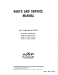
PARTS AND SERVICE
MANUAL
SKI-DADDLER
SNOWMOBILES
MARK IV [SD15P1DA]
MARK
V [SD1BE2DA]
1969-1970
WESTERN TOOL DIVI SION
Des Moines, Iowa 50302
AMF INCORPORATED
PART NO . 37851
REVISED and REPRINTED
IIINI= 107n
. - - - - - - - - - WARRANTY SERVICE - - - - - - - - - ,
Warranty service policy is printed below and
on the warranty registration card included with
the unit. The registration card must be filled in
and mailed to the manufacturer. The card is
postage paid. Warranty service will be handled
by all authorized AMF Ski.Daddler dealers.
•
•
SNOWMOBILES
•
•
Your Manual No. _ _ _ _ _ _ _ _ _ is a registered number. Additional parts and service
information will automatically be sent to you.
~~~~~~~~~~~~~~~~~~~~~~~~
~~
~~
WARRANTY CERTIFICATE
AMF SKI-DADDLER SNOWMOBILE
~t.
~~
;~
AMF WESTERN TOOL DIVISION warrants this vehicle to the first retail purchaser to be free from defects in mao
terial and workmanship for a period of ninety days from its first operation (thirty day limit on commercial use and
thirty day limit on rental service). This shall be limited to replacing free of charge, F.O.B., Des Moines, Iowa,.any
defective part provided that:
1. Vehicle has not been subject to accident or misuse.
2. No repairs or alterations have been made outside of our factory or factory approved service station in any
respect which in our judgment affects its condition or operation.
3. Defective parts must be returned by authorized dealer within 30 days after failure.
4. That our examination of the part has disclosed to our satisfgction the defect.
5. Warranty does not apply, if the vehicle in question has been used by an authorized dealer or any other person
prior to the original retail sale.
This warranty does not cover normal wear or apply if the sled has been subject to misuse, competition raci,!g, negli·
gence, accident, or submersion under water, or operated on any surface other than snow or ice.
AMF WESTERN TOOL DIVISION shall not be responsible for damage in transit or handling by any common
contract carrier.
Under no circumstances, within or without the warranty period, will the Company be liable for damages, for loss of
use, or damages resulting from delay or any consequential damages.
~
This warranty is in lieu of all other warranties expressed or implied, and all other obligations or liabilities on the
part of AMF WESTERN TOOL DIVISION. The Company reserves the right to incorporate changes in design into
this product without obligation to make these changes on units previously sold.
f'"
~
~)
~
;~
~
~)
.~
.~
~
~)
~.
\Jj
~~
\~'
~
~
IMPORTANT
~~~)
While the warranty covers defects in material and workmanship, certain maintenance items as listed below are considered
normal operating expense items and are not covered under the
f4
~)
~
~~
warranty.
1. Engine tune-up cleaning or replacement of spark plugs.
2. Ski Alignment.
f4
Brake, variable speed, or traction belt adjustment, or
. variable speed belt replacement .
4. Brake lining or ski wear rod replacement.
~
5 . Paint, body dents, damaged fiberglass, and chrome
trim damage due to use
~)
~)
3
l '"".
~)
6
Of
clutch or traction belt damage due to running engine at
high RPM on kickstand, or with variable speed belt
removed.
7. Broken windshields.
8. Any modifications other than factory recommendations.
g. Use of sled for competition racing will void warranty
10 . Traction belt failure due to misalignment or abuse.
Engine damage due to lack of suffiCient od In fuel mlx-
000"'"'' ",I. '""
1o," wbo,","' ,d,o"mo",. "'
f~
~
~,
~
f~
~
r.;
'\
~
f~
~
~,
~f"
f""
'~~"i
~
f~
~~~,.
fl
?~
~
~.
~
f~
~
f~
~
r.;
~
..~ ~~~~~~~~~~~~~~~~~~~~~~~
Include the complete (8 digit) model number as shown on
Model Plate when ordering parts or asking for information.
Due to slight engineering changes, this is for identification
purposes only .
J
)
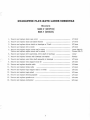
GUARANTEE FLAT-RATE LABOR SCHEDULE
Models
MARK IV (SD15Pl0A)
MARK V (SD18E20A)
1. Remove and replace chain case cover
1/4 hour
2. Remove and replace chain and adjust tension
1/4 hour
3. Remove and replace driven clutch or bearings or V-belt •..............•....•.•.....•....
1/2 hour
4. Remove and replace drive clutch
1/2 hour
5. Remove and replace engine mount and/or strap ............................................ .
Remove and replace engine mount and/or strap ............................................ .
1 hour (Mk IV)
2 hours (Mk V)
6. Remove and replace drive sprockets, drive shaft or bearings .......................... .
1 hour
7. Remove and replace traction belt (endless) and adjust
2 hours
................ .. ............. . .
r""-
8. Remove and replace rear idler shaft assembly or bearings .................. . .......... .
1/2 hour
~
9. Remove and replace rear support arms (2) .................................................. .
1/2 hour
10. Remove and replace throttle cable
1/4 hour
11. Remove and replace brake cable
1/4 hour
12. Remove and replace bogie support half (lor both)
1/2 hour
13. Remove and replace bogie wheel .................................................................
1/4 hour
14. Remove and replace steering spindle
1/4 hour
15. Remove and replace spindle arm ............................•.............................. ... ...
1/4 hour
16. Remove and replace carburetor ............ .... ... . ... .•........ .... ...... ......... ... .... .. .. ...
3/4 hour
1
~t!Mlal
I~
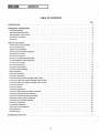
CONTENTS
)
TABLE OF CONTENTS
Page
INTRODUCTION . . . . . .
.3
PREDELIVERY INSTRUCTIONS
In stall Ski Assembly . . . .
Install Windshield Assembly
Activate Battery- Mark V Only
Fuel Mixture Instructions
Lubrication . . . . .
.3
.3
.4
.4
.4
.5
.5
.5
.5
.5
.6
.6
.7
.7
.7
.8
.8
.8
.8
.9
.9
.9
10
SERVICE AND REPAIR
Hood Removal and Installation
Hood Assembly Repair . . . .
Replace Lamp Assemblies. . .
Steering and Ski Assembly Alignment
To Remove Drive Chain. . . . . . .
Drive Chain Adjustment . . . . . .
To Remove Variable-Speed Drive Belt.
Variable-Speed Drive Belt Adjustment .
To Remove Drive Clutch
Drive Clutch Alignment . .
To Remove Driven Clutch .
To Remove Brake Assembly
Brake Adjustment . .
To Remove Carburetor . .
Carburetor Adjustment . .
To Remove Starting Motor Assembly- Mark V Only
To Remove Engine and Support Assembly-Mark IV Only.
To Remove Engine and Support Assembly- Mark V Only
To Remove Gas Tank . .
To Remove Muffler
To Remove Bogie Wheel
To Remove Bogie Wheel and Support Assembly
To Remove Bogie Wheel Torsion Springs. .
To Remove Traction Belt Take-Up Assembly
To Remove Sprocket Seals and Bearings
To Remove Drive Sprocket Assembly
To Remove Traction Belt
Traction Belt Adjustment . .
Spark Plug Interchangeability
Wiring Diagrams
Troubleshooting . . . .
II
II
J2
J2
J3
J3
13
13
J4
J4
J4
J5
J6
J6
J6
• J
ILLUSTRATED PARTS LIST
2
INTRODUCTION
INTRODUCTION
This manual has been prepared to provide all
authorized AMF Ski-Daddler Dealers, Distributors
and technicians with the instructions necessary to
service and maintain the 1970 AMF MARK IV
(SDI5PI0A) and MARK V (SDI8E20A) Ski-Daddler
snowmobiles.
This manual is presented in two sections. The first
section, Maintenance, provides the instructions
necessary for maintenance and service while the
second section, the Illustrated Parts List is provided to facilitate the ordering of spare and replacement parts.
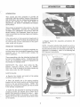
Figure I
If the information in this manual is not applicable to
the Mark IV and Mark V models, the exceptions will
be noted and the correct information for the particular model will be given.
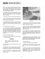
• Repeat Install Ski Assembly procedures for
opposite ski.
NOTE: Properly installed skis should toe out 0- to
1/2-inch at the front end (see figure 2) and should
be symmetrical about the centerline of the sled. If
alignment is necessary, refer to the Steering and
Ski Alignment procedures.
PREDEL/VERY INSTRUCTIONS
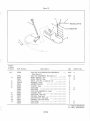
The 1970 Ski-Daddlers are shipped completely assembled except for the windshield assembly, the ski
assembly and on the electric-start models, the
battery assembly.
MOUNTING STRIP, RH
These assemblies, plus the attaching hardware will
be found in the shipping carton. Carefully open the
carton and immediately inspect the eqUipment for
any damage or missing items.
,W
--
MOUNTING STRIP, lH
I NOSH I ElO TR 1M
\--
"
IMPORTANT: The owner must retain the SkiDaddler Inspection Record, Form No. 4477QA.
This form must be shown to the dealer should any
claim arise under the AMF Guarantee.
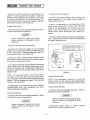
Install Ski Assembly
(8
• Remove the locknut and screw at the spring
mounting bracket (figure 1).
• Place the spindle pad in the spring mounting
bracket with the thicker section and the directional
arrow on the pad pointing forward. NOTE: The
plastiC bag containing the spindle pad will be found
in the storage compartment.
• Install the ski assembly by securing the spring
mounting bracket and spindle pad to lower end of
spindle tube assembly as shown in figure 1. Apply
30 foot-pounds torque to the locknut. Do not overtighten bolt as the ski assembly should float freely
on the spindle.
TOE OUT 0- TO liZ-INCH MAXIMUM
Figure 2
3
)
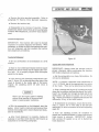
Install Windshield Assembly
• Remove the screws securing the left- and righthand mounting strips to the hood. Remove the
mounting strips.
• Remove the protective plastic cover from the
windshield. Place the windshield in position On the
hood assembly. Replace the mounting strips as
shown in figure 2.
• Using the original screws, loosely secure the
mounting strips and windshield to the hood assembly
starting at the center and working to the sides.
• Engage the ends of the mounting strips in the
trim strip on the windshield and then tighten the
screws, again starting at the center and working to
the sides. NOTE: Check mounting strips for sharp
edges or corners. Use a fine tooth file to smooth
all edges and corners.
Figure 3 -Mark V Only
Fuel Mixture Instructions
I WARNING
Activate Battery-Mark V Only
I
Never fill the gasoline tank while the
engine is hot.
Wipe off any spilled
gasoline before attempting to start
engine.
• Remove the hood and headlight assembly. Refer
to Hood Removal and Installaion.
The correct oil-to-gasoline ratiO is 20: 1 (20 parts
regular gasoline to 1 part oil). Too much oil will
cause carbon deposits. Too little oil or a poor mix
will cause insufficient lubrication and possible
engine damage.
Before activating the 12-volt storage
battery, disconnect the battery cables
and remove the battery. Activate the
battery in accordance with the instructions contained in the battery package.
Reinstall the battery as follows:
IMPORT ANT: Gasoline and oil should be mixed at
temperatures above zero. At temperatures below
zero, gas and oil mix with difficulty.
• Place 12-volt battery On the battery support
plate with positive (+) terminal post forward (see
figure 3).
Fuels containing additives are not recommended for
use in Ski-Daddler engines. For mixing with gasoline, use only oil that is recommended for use in
air-cooled, 2-cycle engines such as an AMF oil or
an equivalent good grade of SAE 30 or 40 nondetergent motor oil.
• Attach the positive (+) battery cable and the
RED wire lead (from cigarette lighter) to thepositive terminal post.
• Attach the negative (- ) battery cable and the
BLACK wire lead (from cigarette lighter) to the
negative terminal post.
IMPORT ANT: Some outboard motor oils contain a
detergent that works well in outboard motors that
operate at much lower temperatures because they
are water cooled. However, the detergents may
cause spark plug fouling in the air-cooled engines
used on your Ski-Daddler.
• Position the holddown strap across the battery
and over the holddown rods. Secure the strap and
battery using locknuts and washers. Do not overtighten.
Use a mixture of gasoline and oil as shown in the
Fuel Mixture Chart. Never use gasoline left over
from the summer or previous winter.
• Replace the hood and headlight assembly.
4
~I SERVICE AND REPAIR leMla~
c
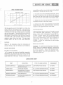
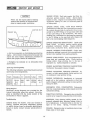
FUEL MIXTURE CHART
assemblies and then remove the hood and headlight
assembly by lifting rear section first.
GASOLINE-Oil RATIO
2
0
I
L
1-1/2
./
P
I
N
./
1/2
T
S
/
• To install the hood and headlight assembly, place
the hood in position on the sled so that the forward
hood clip and the bottom edge of the hood engages
the clips along the inside edge of the bumper strip.
V
V
~
• Engage the left- and right-hand latch assemblies
to secure the hood to the main frame.
~
2
3
4
5
• Connect the sled wiring harness to the hood
wiring harness at the quick-disconnect below the
console on the right-hand side of the sled.
GASOLINE. GALLONS
Mix the gasoline and oil thoroughly in a clean container kept for this purpose only. The best way to
ensure a good mix is to pour the oil into the empty
container and then add a small amount of gasoline
and mix thoroughly. Then add additional amounts of
gasoline as shown on the Fuel Mixture Chart. Fill
Ski-Daddler gas tank from this separate container
of mixed fuel. Use a funnel with a fine-screen
strainer when filling the tank. The gas cap is
located under the gas lid and hinge assembly.
c
Hood Assembly Repair
AMF Fiberglass Repair Kits are available through
your authorized AMF Distributor. For large repairs, order AMF Fiberglass Repair Kit No.
1510693. Smaller repairs can be made with Repair
Kit No. 1510765. Paint all repaired areas on the
hood using AMF -Orange color paint available in
easy-to-use spray container, AMF Part No.
1510828. Follow the instructions in the kit when
making repairs.
Lubrication
Replace Lamp Assemblies
Refer to the lubrication chart for lubrication of
grease fittings, type of lubricant and frequency.
Headlight. To replace the headlight lamp assembly,
simply raise the headlight assembly, remove the
screws securing the cover assembly and remove
the cover assembly. Remove the defective headlight and replace with new lamp assembly. See
illustrated parts list.
SERVICE AND REPAIR
Hood Removal and Installation
• To remove the hood and headlight assembly,
disconnect the hood and the sled wiring harness
at the quick-disconnect below the console on the
right-hand side of the sled. Release the hood latch
LUBRICATION CHART
PART
LOCATION
TYPE OF LUBRICATION
FREQUENCY
STEERING SPINDLES
GREASE ZERK FITTINGS ON
SPINDLE HOUSINGS
LOW-TEMPERATURE GREASE
20 HOURS
DRIVE CHAIN
CHAINCASE HOUSING
NO.2 LITHIUM BEARING GREASE
20 HOURS
BOGIE WHEELS
GREASE ZERK FITTING IN
CENTER OF BOGIE WHEEL
LOW-TEMPERATURE GREASE
20 HOURS
SPROCKET BEARINGS
REAR SPROCKETS
NO.2 LITHIUM BEARING GREASE
40 HOURS
STEERING COLUMN
U-STRAP AND WEARPLATES
AT ROLL BAR
NO.2 LITHIUM BEARING GREASE
AS REQUIRED
5
~t.aMlal SERVICE AND REPAIR I~
Taillight.
the seat
assembly
move the
bulb. See
Remove taillight lens and cover, or lift
assembly to expose the rear console
containing the twin taillight bulbs. Redefective bulb and replace with a new
illustrated parts list.
• Move the affected ski into proper alignment and
recheck measuring points to insure that the skis
toe out 0- to 1/2-inch maximum at the front end and
are in the same orientation with the sled body as
shown in figure 2.
• With skis properly set and steering handle in
the straight-ahead position, rotate tie rod (5, figure
4) as required to bring rod end bearing (3) in line
with the spindle arm (6).
Steering and Ski Assembly Alignment
Good steering ability requires that the skis be
properly set and aligned with the sled body when
the steering hand1:e is placed in the straight-ahead
position. To determine that the skis are properly
aligned, measure the distance between the inside
edges of the skis at the front end and at the rear.
Properly aligned skis should toe out 0- to 1/2-inch
maximum at the front.
Therefore, the overall
measurement at the front end of the skis should be
1/2 inch greater than at the rear. If the skis or
steering mechanism are not properly set, adjust
as follows.
• Secure rod end bearing (3) to spindle arm (6)
as illustrated. Check for proper alignment and then
tighten jam nuts (4) to secure both rod end bearings.
NOTE: If a greater adjustment is required than that
permitted by the steering linkage assembly, it will
be necessary to align the ski by making the adjustment at the spindle tube assembly as follows:
• Remove screw (5, figure 5), washers and locknut
(6) securing spindle tube assembly (7) to spindle
arm (8).
• Place steering handle in a straight-ahead position.
• Remove the hood assembly.
• Remove the bolt (1, figure 4), two spacers (2),
bottom spacer and locknut securing the rod end
bearing (3) to the spindle arm.
• Loosen the jam nuts (4) securing both rod end
bearings (3) to the tie rod (5).
NOTE: If both skis need adjustment, repeat procedllre for the opposite ski.
Figure 5
• Remove spindle arm (8) and rotate ski and
spindle tube one notch in the required direction;
replace and secure spindle arm to the spindle tube.
Apply 20 foot-pounds torque to the locknut (6).
• Recheck the skis for proper toe out and alignment as previously described.
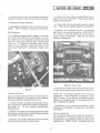
To Remove Drive Chain
• Remove the hood and headlight assembly. Refer
to Hood Removal and Installation.
Figure 4
6
)
~I SERVICE AND REPAIR
c
to the main frame. During reassembly, apply 10
foot-pounds torque tel> the locknut (9).
CAUTION!
Always disconnect spark plug wires
before working on the engine or drive
elements.
• Push tlte driven clutch toward the drive clutch
sufficiently to allow removal of the variable-speed
drive belt from the drive clutch.
• Release the chain cover straps and remove the
chain cover tou.
• Remove the locknuts (7, figure 4) and washers
securing the bearing clamps (8) and remove the
bearing clamps. During reassembly, apply 5 footpounds torque to the locknuts (7).
• Loosen the bolts (1, figure 5) on both cam uprights (2) and rotate the cam and shaft (3) as required to loosen the chain tension. During reassembly, apply 30 foot- pounds torque to the bolt (1).
• Lift the driven clutch (9) and drive belt clear
of the brake assembly (10) and away from the chain
case.
• Remove the cotter pin, slotted nut and washer
securing the top sprocket to the driven clutch shaft.
Rell10ve the top sprocket and chain together. During
reassembly, add No.2 Lithium bearing grease to the
chain case.
• Remove the variable-speed drive belt.
NOTE: Variable-speed drive belt installation procedures are the reverse of removal except that the
belt must first be placed around the driven clutch
and then around the drive clutch. After installation,
perform the drive chain adjustment, variable-speed
belt adjustment and the drive clutch alignment
procedures.
• Reassembly is the reverse of removal. Perform
drive chain adjustment procedures.
Drive Chain Adjustment
A properly adjusted drive chain (figure 5) should
have a 1/8- to 1/4-inch slack. Check and adjust
chain as follows:
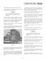
Variable-Speed Drive Belt Adjustment
Proper tension for a new drive belt should be obtained when the clutch centers are set apprOximately
10-3/4 inches apart (see figure 6). Proper tension
for a drive belt that has been used is obtained when
opposite sides of the belt can be squeezed, between
the drive clutches to the following dimensions:
• Release the chain cover straps and remove the
chain cover.
• Check chain for proper slack. If adjustment is
required, loosen the screws (1) securing the cam
blocks (2) on each side.
Mark IV
Mark V
• Rotate the cam (3) counterclockwiseto tighten or
until the chain is properly tensioned. Hold the cam
in this position while tightening the cam block
screws (1) on each side. Be certain the lateral
alignment between the drive clutch and the driven
clutch (4) is maintained while the cam block screws
are tightened.
2-3/4 to 3-1/4 inches
4 to 4-1/2 inches
The measurement must be taken between the top
and bottom outside surfaces of the belt a..T1d as close
to the drive clutch flanges as possible. Be certain
the driven clutch does not open when belt is
squeezed.
IMPORTANT: Do not use antislip belt dreSSing.
Use of belt dreSSing will void the owner's guarantee as belt slippage is a safety feature which
prevents overstressing the drive-system components.
• Recheck chain tension before replacing the chain
case cover.
To
leSaaij
Remove Variable-Speed Drive Belt
• To adjust drive belt tension, loosen the locknut
(9, figure 5) securing the clutch rod tensioner to the
main frame assembly.
• Remove the drive chain. Refer to paragraph To
Remove Drive Chain.
• Remove the clutch guard assembly.
NOTE: If the drive belt is wearing unevenly, check
drive belt alignment as described in Drive Clutch
Alignment procedures.
• Loosen the locknut (9, figure 5) and serrated
washer (10) securing the clutch rod tensioner (11)
7
~eSial SERVICE AND REPAIR I~
• Move the driven clutch (4) in the direction required to obtain proper belt tension. Hold this
position while tightening the locknut (9) to secure
the clutch rod tensioner. Be certain the washer (10)
and bar serrations are properly engaged. Apply 10
foot-pounds torque to the locknut (9).
J
• Remove the clutch guard.
• Loosen the engine holddown nuts securing the
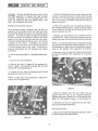
supports to the engine mount straps as
illustrated in figure 6.
~ngine
• Place a straightedge on the fixed face of the
drive clutch and move the engine until the offset
between the straightedge and the front and rear
edges of the driven clutch is as shown in figure 6.
Rotate driven clutch 90-degrees and repeat procedure.
To Remove Drive Clutch
• Remove the hood and headlight assembly. Refer
to Hood Removal and Installation.
• Tighten engine holddown nuts and recheck alignment. Apply 25 foot-pounds torque when tightening
the engine holddown nuts.
Always disconnect spark plug wires
before working on the engine or drive
elements.
• Remove the clutch guard assembly.
DIMENSION MARK IV MARK V
• Loosen the locknut (9, figure 5) and serrated
washer (10) securing the clutch rod tensioner (11)
to the main frame. During reassembly, apply 10
foot-pounds torque to the locknut (9).
DR I VEN CLUTCH
®
INCHES
0.240
0.30
• Push the driven clutch toward the drive clutch
sufficiently to allow removal of the variable-speed
drive belt from the drive clutch.
)
• To remove the Mark IV drive clutch, remove the
clutch adapter bolt and washer securing the drive
clutch, if necessary use aclutchpuller. During reassembly, apply 70 foot-pounds torque to the clutch
adapter bolt.
L
DRIVE CLUTCH
t
VIEWe~
VIEW"
Figure 6
NOTE: To remove the Mark V drive clutch, flatten
the tangs on the lock plate and remove the clutch
bolt, lock plate, Belleville washer and the r.etaining
washer. During reassembly, apply 70 foot-pounds
torque to the clutch bolt.
To Remove Driven Clutch
NOTE: The procedures required to remove the
driven clutch are the same as those described in
paragraph To Remove Variable-Speed Drive Belt.
• Reassembly is the reverse of removal. Perform
variable-speed drive belt adjustment and drive
clutch alignment procedures.
To Remove Brake Assembly
• Remove hood and headlight assembly. Refer to
Hood Removal and Installation
Drive Clutch Alignment
• Remove the hood and headlight assembly. Refer
to Hood Removal and Installation.
{ CAUTION
Always disconnect the sparkplugwires
before working on the engine or drive
elements.
I
Always disconnect spark plug wires
before working on the engine or drive
elements.
• Disconnect brake cable at brake mounting
bracket and at brake actuating lever.
8
)
SERVICE AND REPAIR
c
geld
• Release the hose clamp and disconnect the impulse line at the carburetor. Wipe up any spilled
gasoline immediately.
• Remove the two bolts and locknuts securing the
mounting bracket to the driven clutch mounting.
• Remove the brake assembly.
• Release the tank-to-carburetor gas line (figure
10). Wipe up any spilled gasoline immediately.
• Installation procedures are the reverse of removal. Refer to Brake Adjustment procedures.
• Release the carburetor-to-tank recirculating
gas line at the recirculation elbow. IMPORTANT:
Be certain to note the position of the gas lines to
insure proper reassembly. Wipe up any spilled
gasoline immediately.
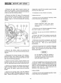
Brake Adjustment
• To adjust the brake pads (5, figure 7) to the disk
(1), remove the cotter pin (2) and tighten or loosen
the castle nut (4) as required to permit the brake
pads (5) to just clear the brake disk. Reinstall the
cotter pin. To adjust for excessive play in brake
cable or lever position, loosen jam nuts (6) and
move brake housing (7) as required. Tighten jam
nuts.
c
Figure 8 -Mark V Only
• Remove the metric nuts securing the carburetor
to the intake manifold and remove the carburetor.
Figure 7
To Remove Carburetor
NOTE: Do not damage gaskets when remOving
carburetor. When replacing carburetor on the
Mark V sleds, do not remove the throttle bracket
unless it is necessary due to a damagedb:racket or
when replacing the gaskets.
To gain access to the carburetor, remove the console door assembly by turning the door fastener
counterclockwise to release the door lock.
• Loosen throttle- and choke-control cable adjustment screws and release both cables at carburetor
(see figure 8). Do not misplace throttle-wire
reinforcement.
• Installation is the reverse of removal. Adjust
carburetor as deSCribed in Carburetor Adjustment
procedures.
• Remove the three screws.securing the air intake
filter (figure }O) and choke control bracket mounted
on the Mark IV carburetor 'only.
Carburetor Adjustment
The carburetor used on the Mark IV and Mark V
Ski-Daddlers is a Tillotson Model HD carburetor
equipped with a recirculation system for better sled
performance. NOTE: Never run engine with the
• Release the throttle extension spring and hook
at the carburetor throttle control lever.
9
~t'·':4Mlal SERVICE AND REPAIR I~
carburetor-to-tank recirculating gas line disconnected.
• Disconnect the battery-to-solenoid positive (+)
cable at the battery to prevent sparking and possible
shorting.
When adjusting the carburetor, best results will
be obtained if the adjustments are made on a warm
engine. During carburetor adjustments, DO NOT
FORCE ADJUSTMENT SCREWS INTO SEATS.
• Disconnect the sOlenoid-to-starting motor cable
at the starting motor.
• Back off the upper nut securing the battery-tostarting motor negative (-) groWld cable.
NOTE: To gain access to the carburetor adjustments, remove the console door assembly by
turning the door fastener cOWlterclockwise to
release.
• Back off the two nuts securing the starting motor
assembly to the engine. Remove the groWld wire
from the engine wiring harness and the battery-tostarting motor groWld wire attached to the upper
stud and remove the starting motor assembly.
• TO ADJUST CARBURETOR - Close the highspeed jet shown in figure 8 (DO NOT FORCE). Then
open as shown in the carburetor adjustment chart,
figUre 9.
• Reassembly is the reverse of removal.
CARBURETOR ADJUSTMENT
SKI-DADDLER
MODEL
)
CARBURETOR
LOW-SPEED JET
HIGH -SPEED JET
(TURNS)
(TURNS)
~/8 Open
MK- IV
Tillotson HD 39A
(AMF No. 37258)
1-1/8 + 1/8 Open
- 0
3/4 :
MK-V
Tillotson HD 39A
(AMF No. 37258)
1-1/8 + 1/8 Open
- 0
1 + 1/8
o Op en
-
)
Figure 9
• Turn the low speed jet (idle-mixture screw)
shown in figure10 'a ll the way in (DO NOT FORCE),
then open as shown in figure 9 for the particular
model sled. This adjustment controls the mixture
at idling speeds. A lean idle mixture will result
in poor acceleration.
Keep the idle speed slower than the clutch engaging
speed by adjusting the idle-speed screw. NOTE: Do
not use the low-speed jet to adjust for idle speed.
NOTE: Figure 10 shows a throttle~wire adjustment
screw. If the throttle plate fails to open completely
when the throttle control lever is depressed, loosen
the throttle-wire adjustment screw and readjust the
wire as required to open the throttle.
To Remove Starting Motor Assembly- Mark V Only
• Remove the hood and headlight assembly. Refer
to Hood RemOVal and Installation.
)
Always disconnect spark plug wire
before working on the engine or drive
elements.
Figure JO
JO
SERVICE AND REPAIR
c
• Remove the heat shield located between the
engine and the muffler. Remove the attaching hardware at the muffler bracket, heat shield bracket and
at the top near the steering column.
To Remove Engine and Support Assembly-Mark IV Only
• Remove the hood and headlight assembly. Refer
to Hood Removal and Installation.
[
C~~TION
• Remove the locknuts and washers securing the
engine mounting straps to the main frame.
1
Always disconnect the sparkplugwires
before working on the engine or drive
elements.
• Lift the engine until the engine mounting straps
clear the studs shown in figure 11. Rotate the
engine counterclockwise and remove the engine
toward the rear and clear of the sled.
• Remove the console door assembly by turning
the door fastener counterclockwise to release.
• Remove the carriage bolts, washers and locknuts
securing the mounting straps to the engine base.
Remove the mounting straps and bar washers.
NOTE: During reassembly, the mounting straps
and bar washer must be secured to the engine base
before installing the replacement engine.
• Remove the six screws, washers and locknuts
securing the console tongue assembly to the tool
box and to the mini-console (see figure 11).
• Remove the drive clutch.
To Remove Drive Clutch.
Refer to
PSld
parag~aph
• Installation procedures are the reverse of
removal.
• Loosen the flexible tube clamps. securing the
muffler exhaust tube to the engine exhaust manifold
and release the exhaust tubes.
To Remove Engine and Support Assembly- Mark V Only
• Remove the hood and headlight assembly. Refer
to Hood Removal and Installation.
!
CAUTION
I
Always disconnect the sparkplugwires
before working on the engine or drive
elements.
• Remove the console door assembly by turning
the door fastener counterclockwise to release.
• Remove the six screws, washers and locknuts
securing the console tongue assembly to the tool
box and to the mini-console (see figure 11).
• Remove the drive clutch.
To Remove Drive Clutch.
Figure 11
Refer to paragraph
• Loosen the flexible tube clamps securing the
muffler exhaust tube to the engine exhaust manifold
and release the exhaust tubes .
• Disconnect the throttle and choke control cables
and remove the carburetor as described in paragraph To Remove Carburetor.
• Disconnect the throttle and choke control cables
and remove the carburetor as described in paragraph To Remove Carburetor.
• Disconnect the yellow wire lead and the black
wire lead at the engine and the black ground wire
lead at the starter cover. Replace the metric nut
to secure the cover after removing the black wire
lead.
• Remove the starting motor assembly. Refer to
paragraph To Remove Starting Mot0r Assembly.
11
~p.!Mlal SERVICE AND REPAIR I~
• Remove the heat shield located between the
engine and the muffler. Remove the attaching hardware at the muffler bracket, heat shield bracket and
at the top near the steering column.
reassembly, apply 25 foot-pounds torque to the nuts
securing the engine base.
• Remove the bolts (10, figure 12), spacers and
nuts securing the steering linkage to the steering
column arm (9). During reassembly, apply 15 footpounds torque to the nuts securing the steering
linkage.
To Remove Gas Tank
)
• Installation is the reverse of removal .
• Remove the hood and headlight assembly. Refer
to Hood Removal and Installation.
!
CAUT~ON
1
Always disconnect spark plug wires
before working on the engine or drive
elements.
• Check gas cap and indicator assembly to be certain tank is empty, or nearly empty.
• Remove the gas cap and indicator assembly (1,
figure 12).
• Remove the bolts (3) and washers securing the
gas spill chute (2) to the main frame and remove
the gas spill chute.
• Disconnect the tank-to-carburetor gas line (6)
and the recirculating gas line (7) at the gas tank
outlet fitting (5). Wipe up any spilled gasoline
immediately.
• Remove the gas tank (4) by carefully sliding the
tank up and away from the main frame. IMPORTAm: Do not damage the gas tank outlet (5) when
removing the tank.
Figure 12
• Remove the bottom cotter pin securing the
steering column to the main frame steering column
support.
LCAUTIO~: I
Do not attempt to make any repairs to
the gas tank. Use extreme care when
removing the gas tank. Do not remove
tank near flame or open fire.
• Oisconnect the wiring harness at the battery,
electrical panel, rear console and engine. Release
the wire V-clips in the tool box and at the foot rest
and remove the wiring harness.
• Remove the two screws, formed washers and
locknuts at each end of the roll bar and remove the
roll bar, steering column and mini-console as a unit.
• Gas tank installation procedures are the reverse
of removal. NOTE: If the original tank is not to be
installed, it will be necessary to remove the gas tank
outlet (5) and the attached gas line filter; also the
pressure relief valve (8). These items are to be
installed on the replacement tank.
• Remove the locknuts and washers securing the
engine mounting straps to the main frame studs,
and remove the engine, engine base and mounting
straps.
To Remove Muffler
• Remove the carriage bolts, nuts and washers
securing the engine mounting straps to the engine
base. Remove the straps for reassembly. During
• Remove the hood and headlight assembly. Refer
to Hood Removal and Installation.
12
)
VICE AND REPAIR
c
To Remove Bogie Wheel and Support Assembly
Always disconnect the spark plug wires
before working on the engine or drive
elements.
Always disconnect the sparkplugwires
before working on the engine or drive
elements.
• Loosen the flexible tube clamp securing the
flexible exhaust tube to the muffler and release the
tube. NOTE: The Mark V Ski-Daddler has dual
exhaust tubes and muffler.
• Place the Ski-Daddler on the kickstand.
• Remove the screws (1, figure 13) and washers
securing the bogie wheel support shaft to the main
frame.
• Loosen the bolt and nut securing the muffler to
the mounting band assembly. Remove the muffler.
• Remove the bogie wheel and support assembly.
• Installation procedures are the reverse of
removal.
• Reassembly is the reverse of removal.
To Remove Bogie Wheel Torsion Springs
To Remove Bogie Wheel
• Remove the bogies as described in paragraph To
Remove Bogie Wheel and Support Assembly.
c
Always disconnect the spark plug wires
before working on the engine or drive
elements.
• Remove the support shaft and separate the bogie
wheel support halves.
• Remove the torsion springs.
• Place Ski-Daddler on the kickstand.
NOTE: The torsion springs are identified as rightand left-hand springs. Note the direction of the
coils and the pOSition of the springs to facilitate reassembly.
• Remove the locknut (3, figure 13) securing the
bogie wheel assembly (2) to the axle shaft and remove the wheel.
• During reassembly, torque the locknut (3) to 28
foot-pounds. Be certain the wheel assembly (2) is
installed with grease fittings on the outside.
• Reassembly is the reverse of removal.
To Remove Traction Belt Take-Up Assembly
• Place Ski-Daddler on the kickstand.
• Remove the rear bOgies. Refer to paragraph To
Remove Bogie Wheel and Support Assembly.
• Release track tension by loosening adjusting
bolts (5, figure 13).
• Release the support arm torsion springs connected to the main frame.
• Remove the right- and left-hand adjusting angle
locknuts (6), washers and carriage bolts securing
the traction belt take-up assembly to the main
frame.
• Remove the traction belt take-up assembly as a
unit.
Figure 13
13
SERVICE AND REPAIR
NOTE: The traction belt take-up assembly consists
of the rear sprocket assembly, spacer and associated hardware held together by the rear support
arm assemblies. If necessary to remove seals or
sprockets, proceed as follows.
• Carefully pry the oil seal away from the rear
support arm assembly (8) and remove the support
arm and adjusting angle (9) clear of the sprocket
shaft and bearing.
• Remove the press- on bearings and grease seals.
• Remove the screws (10) and nuts securing the
sprocket plate and the sprocket to the drive shaft.
Remove the plate and sprocket.
Figure 14
• Reassembly is the reverse of removal. During
reassembly follow instructions outlined in paragraphs Track Alignment and Track Tension Adjustment.
• Remove the carriage bolts and nuts securing the
bearing retainer to the chain case side of the main
frame. Remove the retainer.
• Move the drive shaft and sprocket assembly
toward the chain side until the c>pposite end of the
shaft clears the bearing retainer. Remove the drive
sprocket assembly.
To Remove Sprocket Seals and Bearings
• Sprocket seals and bearings are located on each
end of the traction belt take-up assembly and the
drive sprocket assembly drive shafts. To replace
the seals or bearings it will be necessary to remove
the traction belt take-up assembly or the drive
sprocket assembly as described in the applicable
paragraph.
• To replace the sprockets, remove the ball
bearing and oil seal. Remove the screws and nuts
securing the support plate and sprocket to the drive
shaft and sprocket plate assembly. Remove the
sprocket.
To Remove Drive Sprocket Assembly
• Remove the hood assembly and set the machine
on its right-hand side.
• Reassembly is the reverse of removal. During
reassembly follow instructions outlined in the paragraphs Track Tension Adjustment, Track Alignment, and Drive Chain Adjustment.
Always disconnect spark plug wires
before working on the engine or drive
elements.
To Remove Traction Belt
• Place the Ski- Daddler on the kickstand.
• Release the chain cover straps and remove the
chain cover top.
• Remove the bogie assemblies. Refer to paragraph To Remove Bogie Wheel and Support Assembly.
• Remove the lower sprocket from the drive
sprocket shaft and remove the sprocket and chain
as described in paragraph To Remove Drive Chain.
• Remove the traction belt take-up assembly.
Refer to paragraph To Remove Traction Belt TakeUp Assembly. NOTE: It is not necessary to disassemble the traction belt take-up assembly when
remOVing the traction belt.
• Using a screwdriver, carefully pry the oil seals
(figure 14) away from the bearings at each end of
the drive shaft.
14
VICE AND REPAIR
c
• Remove the drive sprocket assembly. Refer to
paragraph To Remove Drive Sprocket Assembly.
• Remove the traction belt.
• Reassembly is the reverse of removal. During
reassembly follow instructions given in paragraphs
Traction Belt Adjustment, and Drive Chain Adjustment.
Traction Belt Adjustment
IMPORT ANT: The traction belt must be checked
regularly for proper alignment and tension. When
necessary to adjust the belt, first perform the traction belt alignment and then complete the traction
belt adjustment procedures.
Traction Belt Alignment
Figure J5
c
• Set the snowmobile on the kickstand on a level
surface.
Traction Belt Tension Adjustment
• Stand to rear of sled and visually check the space
between the frame tunnel and the edges of the traction belt. On a properly aligned track this space
should be the same.
IMPORTANT: Always check the traction belt for
proper alignment before performing the traction
belt "tension alignment procedures.
• Set the snowmobile on a clean, flat surface. Do
not use the k~ckstand.
• If the track is not centered, loosen the two locknuts (1, figure 15) on that side where the edge of the
track is closest to the inside edge of the tunnel.
Tighten the adjusting screw (3) until track is
centered.
NOTE: A properly tensioned track should have a
1 to 1-1/ 4-inch sag at the approximate top center
of the track. This can be determined as follows:
• Rest a straight bar (figure 16) of sufficient length
along the top surface and near the edge of the track.
Insert the straight bar through the back end of the
snowmobile and check for proper 1 to 1-1/4-inch
sag. Repeat procedure on opposite side and note the
difference, if any, in the track tension.
Never run the engine inside a building
without first opening all doors and windows to insure proper ventilation.
• If adjustment is necessary, loosen the two locknuts (1, figure 15) on each side of the sled just
sufficiently to allow movement of the belt-adjusting
angle (2).
• With the snowmobile on its kickstand, start the
engine. Allow track to rotate several turns and then
recheck track alignment to ensure that proper alignment is maintained.
• Turn the adjusting screws (3) clockwise to
tighten and counterclockwise to loosen until proper
track tension is achieved. IMPORTANT: Adjust
both screws (3) equally so as not to disturb the
track alignment.
• After track alignment is complete, tighten all
locknuts (1) and then check traction belt tension as
described in the following paragraph.
J5
~eM131 SERVICE AND REPAIR I~
)
1:: CAUTION
ENGINE STOPS. Fuel tank empty; fuel flow obstruct ed; ignition system faulty. Spark plug(s)
fouled or dirty. Engine too hotandpistons seizing;
carburetor setting too lean or incorrect grade of
oil being used.
Never run the engine inside a building
without first opening all doors and windows to insure proper ventilation.
ENGINE STOPS, FUEL TANK HALF EMPTY.
Carburetor-to-tank fuel line connected incorrectly.
Be certain the gas tank-to-carburetor line is connected to the OUT fitting on the gas tank outlet and
to the inlet fitting on the carburetor. The recirculating line, carburetor-to-tank must be connected
to the IN fitting on the gas tank outlet (figure 12)
and to the recirculating elbow (figure 8).
TRACTION BELT
ENGINE OPERATES IRREGULARLY. Spark plug
loose, fouled or faulty; ignition switch wiring
grounded; carburetor trouble. Engine holddown
bolts loose; carburetor dirty. Ignition timing off.
Figure J6
ENGINE WORKING FOUR-STROKE. Choke shut;
carburetor settings incorrect; dirt preventing carburetor inlet needles from seating properly.
• Set the snowmobile on its kickstand and start the
engine. Allow track to rotate several turns and then
repeat the track tension adjustment procedure to
ensure that proper tension is maintained.
ENGINE LOSES POWER. Poor compression due t o
loose head and crankcase bolts. Faulty ignition;
timing; piston rings sticking due to the use of
improper oil. Carbon deposits in cylinder.
• Retighten the locknuts (1) on both sides of the
snowmobile.
ENGINE BACKFIRES THROUGH CARBURETORS.
Carburetor fuel-supply channel clogged.
Spark Plug Interchangeability
The following tabulation is provided to show correct
spark-plug interchangeability.
Bosch
M175T1
M225T1
M240T1
Champion AC
UK-10
K-9
UK-7
M84
M83
Autolite Lodge
BZ3
HTN18
HTN18
ENGINE BACKFIRES THROUGH EXHAUST. Incorrect or faulty spark plug(s); faulty ignition coil
or condenser; loose ignition wiring.
NGK
ENGINE OVERHEATS. Insufficient or incorrect
grade oil in fuel mixture; carburetor or fuel line
partly clogged; carburetor setting too lean; ignition
timing too slow.
AB-o
A-7
EXCESSIVE FUEL CONSUMPTION. Carburetor
fuel line or gas tank leaking; choke closed; incorrect
carburetor setting.
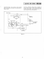
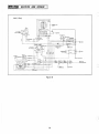
Wiring Diagrams
Electrical wiring diagrams are provided for the
trained technicians using this manual. Each diagram is identified with the model number of the
snowmobile to which it applies.
THROTTLE CONTROL. Excessive play in throttle
control lever caused by loose throttle control cable.
Troubleshooting
STEERING. Poor steering ability caused by improperly adjusted Skis; steering linkage loose or
out of adjustment. U-bracket bolts on roll bar too
tight or too loose.
Spring, U-bracket loose.
ENGINE HARD TO START. Fuel line blocked or
leaking; ruptured fuel-pump diaphragm; ignition
or switch wiring loose or grounded; spark plug(s)
fouled or faulty; contact breaker pOints pitted or
burned.
BRA-KES. Excessive play in handbrake due to loose
brake cable or worn pads.
J6
SERVICE AND REPAIR
c
CLU1'CH. Automatic clutch fails to engage at
proper RPM's: Mark IV, 2000 to 2400 RPM; Mark
V, 2100 to 2500 RPM. Check variable-speed drive
belt for proper tension and alignment.
TRACTION BELT. Poor traction; check traction
belt for alignment and tension; worn sprockets or
flipped bogies.
Mark IV Only
BLACK
BLACK
-=- GROUND AT
STARTER BOLT
TAILLIGHTS
BLACK
GE67
BLACK
QU ICK
DISCONNECT
IGN IT ION SWITCH
HEADLIGHT
60 WATT
GE4466
BLUE
YELLOW
COIL
(75W)
WHITE
JLO
L295 ENGINE
Figure 17
17
SERVICE AND REPAI
)
Mark V Only
-Ifr==
-==-~---;;J
'(75WJI
I
I
r
I
I
NG1NE HIRTH
49312
I
FUSE
AGA-6
I
I
__
YELLOW
..
~TARTER
YELLOW
YELLOW/BlACIC
U
YELLOW
BLACK
RE
BLACK
BLAe
GND AT STARTER
BOLT
z
.•"
SWITCH
r~
_It~"",-/""""""'--<~I
L
L"'j
-
LEFT
WHITE/BLACK
OFF
WHITE/RED
~
~
~
~
m
~
0
~
.~
CIGARETTE
LIGHTER
4-1+-·Hj- _
__ _
_
_
I
J
GND AT STARTER BOLT
RIGHT
- - - - -a"'LiJ'EGREY
r:T.l
1~~!tllj=t!j=~'~"~C~'=E'
c
21
L l
ORANGE
(LOI
II (MI)
(I. GREY
I
r ORANGE
BLACK
QUICK
DlSCONNECT
rl@
I
.,._ _ _ __ --1rHEADLIGHT
I'
L4440 (40W/40W)
LJ
4'SCONNECT
)
Figure 18
J
18
c
C
This Illustrated Parts List is provided to facilitate the procurement of spare parts and sled disassembly in support of all
Ski-Daddler models covered in the Maintenance Section of this
manual. Where component parts or assemblies are common to
all Ski-Daddler models, no model designation follows the item description. Where the component part or assembly applies to a
specific Ski-Daddler model, the model designation will follow in
the description column.
All spare parts necessary to service AMF Ski-Daddlers are available through AMF-Authorized Distributors.
c
PARTS-LIST SECTION
Where no code letter appears in the model column,
the part applies to all models.
This portion of the dealer's manual consists of two
sections, an illustrated parts list and a numerical
index.
All model codes will be listed at the bottom of each
parts listing to provide a ready reference.
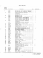
PARTS LIST
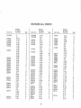
The parts-list portion consists essentially of
exploded-view illustrations, keyed to the figure reference column by index numbers. The list is
arranged in the following columns:
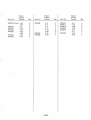
NUMERICAL INDEX
The numerical index is provided to afford dealers
and distributors with a means of determing to which
models their stock applies. The index consists of
the following three columns:
Figure-and-Index Number. The number preceding
the dash refers to the figure number on which the
item is shown. The number following the dash
refers to the part as indicated on the exploded view.
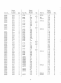
Part- Number Column. The part- number column
tabulates all parts called out in the parts list. The
part numbers are listed in numerical order starting
with the firstdigitin the number. It should be noted,
for example, that a four-digit number starting with
the number 8 would be listed after a five - digit
number starting with a 3 or a six-digit number
starting with a 1.
Part Number. The second column calls out the AMF
part number applicable to the figure-and-index
number and its corresponding index number on the
exploded view.
Description. The description column identifies the
part with descriptive nomenclature. In all cases,
standard hardware is further described with data
covering thread size, length, ID, OD and thickness
where necessary.
Index-Number Column. The index-number column
reflects the figure - and-index number of the part
within the parts list.
Quantity Column. The quantity column reflects the
total number of parts required for the particular
figure-and - index-number application. In certain
cases, quantities differ between sled models. This
circumstance is covered by providing the same
figure-and - index number with different quantities.
In referring to the parts-list section, the proper
quantity per sled may be determined .
Quantity. This column provides the total number of
item units required for the particular application
indicated by the item number.
Model Code. This column codes the Ski-Daddler
models for which the part applies. The following
lists the code-to-model relationship:
• A - MK IV (SD15PIOA)
• B - MK V (SD18E20A)
ilii
I
\.
c
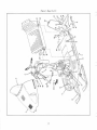
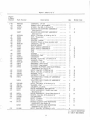
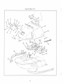
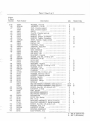
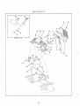
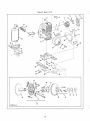
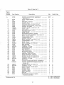
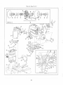
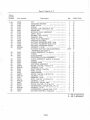
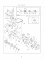
Figure 1. Sheet 1 of 5
Figure
& Index
Number
1-
-1
Part Number
37050
34900
35016
34985
-2
-3
-4
37030
37029
37080
35000
37081
35001
37650
37707
-5
'-6
-7
c
-8
-9
-10
-11
-12
-13
-14
-15
-16
-17
-18
-19
-20
-21
-22
-23
-24
-25
-26
-27
-28
9000305
33808
9000123
9000302
9000123
34916
37245
37184
181573
9416904
33808
446188
9000123
32234
181578
37186
33778
33808
9000123
37176
37175
181575
33808
446188
9000123
37809
33764
-29
-30
-31
-32
-34
9000123
446188
9000124
274865
37351
181581
-35
120392
-33
Description
SKI-DADDLER, MK IV, MODEL NO. SD15PI0A
SKI-DADDLER, MK V, MODEL NO. SD18E20A
HOOD AND HEADLIGHT ASSEMBLY
. •••••••
(See figure 2)
HOOD AND HEADLIGHT ASSEMBLY
••.•.•.•
(See figure 2)
WINDSHIELD, 15-IN.
•..... . ..•... ... ... .
WINDSHIELD, 18-IN.
.......•...•.•......
BUMPER ASSEMBLY, RH (See figure 2)
BUMPER ASSEMBLY, RH (See figure 2)
BUMPER ASSEMBLY, LH (See figure 2)
BUMPER ASSEMBLY, LH (See figure 2)
CONSOLES AND STEERING ASSEMBLY
(See figure 3)
CONSOLES AND STEERING ASSEMBLY
(See figure 3)
SCREW, Truss HD, 1/4 -28 by 1-3/4
.•.....•
WASHER, Formed
...•.•.•.•..•.•......•..
LOCKNUT, 1/4-28
.................. .. ....
. . •. . . . .
SCREW, Truss HD, 1/4-28 by 5/8
LOCKNUT, 1/4-28
........................
SKI AND SPRING ASSEMBLY (See figure 3) ....
SKI AND SPRING ASSEMBLY (See figure 3) •.•.
REAR HANDLE ASSEMBLY
.......••••..••.
BOLT, Hex HD, 1/4-28 by 1-1/4 •.....•.....
. •. ••• . . . . . . . . . . . . . . . • . •
WASHER, Plain
WASHER, Formed
.•..•.••.•...•••.•.•...•
WASHER, Plain
....•.....•.......•.•. "
LOCKNUT, 1/4 - 28
. .••...••. •••••. . .•. ..•.
SPRING, Kickstand
. . • . . . •. . • . . . • . . . . . . . . • .
BOLT, Hex HD, 1/4-28 by 1-7/8 •..•........
SPACER, Long ........•.............. .....
SPACER, Short
........................
WASHER, Formed
•. . . . . . . . . •. •. . . . . •. . . . •
LOCKNUT, 1/4-28
........................
KICKSTAND ASSEMBLY
......•.••.•••..
KICKSTAND ASSEMBLY
. •. •. •. . . . •. •. . •
BOLT, Hex HD, 1/4-28 by 1-1/2 . ...........
WASHER, Formed
. •. . •. . ••••. . . •. . •. •••. •
WASHER, Flat
.•••.•.•...•.•......•••.•...
LOCKNUT, 1/4-28
. • . . •• •. • . •• . • •. . •. ••• •.
REAR CONSOLE SEAT AND TOOLBOX
ASSEMBLY (See figure 4)
REAR CONSOLE SEAT AND TOOLBOX
ASSEMBLY (See figure 4)
LOCKNUT, 1/4-28
. . • •• •. . . • ••• •. • •• ••• • •.
WASHER, Plain
" •. .. ••• . • •• •••. • •. ••• .
LOCKNUT, 5/16-24
....................
WASHER, Plain
. . . . ••. ••••••. •. •••. ••. •
HINGE, Hitch
. . • . • ••. • • •. • ••• • •• • •• •• •• •.
BOLT, Hex HD, 1/4-28 by 2-1/2 . •••.•••••.•
WASHER, Plain
........................
Qty
Model Code
1
1
1
A
B
A
1
B
1
1
1
1
1
1
1
A
B
A
A
B
A
1
B
B
4
4
4
2
2
2
2
2
4
4
4
4
4
2
4
2
2
4
4
1
1
2
2
4
2
1
A
1
B
A
B
A
B
6
6
4
4
1
1
1
A - MK IV (SDI5PI0A)
B - MK V (SDI8E20A)
Figure 1. Sheet 2 of 5
)
)
2
c
c
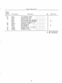
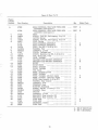
Figure 1. Sheet 3 of 5
Figure
& Index
Number
1 - 36
-37
-38
-39
Part Number
9000123
37122
447811
37120
34927
- 40
-41
-42
-43
-49
-50
-51
-52
-53
-54
-55
-56
-57
9000324
32532
32528
33769
33595
9000125
33768
37582
37698
37801
37801
37583
37584
9000911
9000302
120392
9000123
37344
37345
37765
-58
-59
-60
-61
-62
181566
181003
120392
9000123
37203
-44
-45
-46
- 47
-48
34924
-63
- 64
-65
-66
-67
9000322
456145
9000124
37083
34901
- 68
- 69
-70
-71
34904
181595
138485
34960
37145
37115
-72
34928
- 73
181643
Description
LOCKNUT, 1/4- 28
. •.......•....•.... .. •..
MODEL TAG, Ski-Daddler
............... .
SCREW, Pan HD, 8 - 32 by 3/8
........... .
ENGINE AND SUPPORT ASSEMBLY
.....•..
(See figure 5)
ENGINE AND SUPPORT ASSEMBLY
....... .
(See figure 5)
BOLT, Carriage, 3/8-24 by 2-1/4
....... .
NUT, Tinnerman
..•............ .. •.•..•.
BUSHING
..•.............•......•.. . •....
SPACER, Rubber
....................... .
WASHER (Used on three mounts only) .•......
LOCKNUT, 3/8-24
....................... .
SHOCK MOUNT
.........••.•......•.••.
HEAT SHIELD ASSEMBLY
............... .
HEAT SHIELD ASSEMBLY
............... .
PAD
•........ .......•...•................
PAD
••...••.....••..•.....•..••..•.• ....
GASKET
..•.............•........•..•.•.
GROMMET, Half
..... ••. •.•••.•..•..••..
GROMMET
........•..••...•....•......
SCREW, Truss HD, 1/4-28 by 5/8
•••..•.•
WASHER, Plain
.•..•.••.•.•.•.. . •.... ..
LOCKNUT, 1/4-28
.....•••••.•••.•.••....•
BRACKET, Heat shield
•••.••.•.•...• •• .•..
SUPPORT, Heat shield
•.•.••••.•.•.•..•..•
BATTERY SUPPORT AND ELECTRICAL
ASSEMBLY (See figure 6)
BOLT, Hex HD, 1/4-28 by 3/4
••..•.••..••
BOLT, Hex HD, 1/4-28 by 5/8
.••••••••••.
WASHER, Plain
••.•....•. •..••.•••.•..•
LOCKNUT, 1/4-28
....•..•••••••••.••..•..
TRACTION BELT TAKE - UP ASSEMBLY
(See figure 7)
TRACTION BELT TAKE-UP ASSEMBLY
(See figure 7)
BOLT, Carriage, 5/16 - 24 by 3/4·
.•......
WASHER, Flat
.••...•••••••.•.••••••••••••
LOCKNUT, 5/16-24
...... '" .......... .
BOGIE ASSEMBLY (See figure 8) ..••••.•...•
BOGIE ASSEMBLY, Middle and rear
.•......
(See figure 8)
BOGIE ASSEMBLY, Front (See figure 8)
SCREW, Hex HD, 5/16-24 by 3/4
•••..•••
LOCKWASHER
.•..•..••.•••.•.....••.••...
BELT, Traction
..••...••••••.•••••••..•
BELT, Traction
..•.•.•••••..•.••• .•.•..
DRIVEN CLUTCH AND MOUNTING
.•..•.••
ASSEMBLY (See figure 9)
DRIVEN CLUTCH AND MOUNTING
ASSEMBLY (See figure 9)
BOLT, Hex HD, 3/8-24 by 1-1/2
..••..•••••
Qty
Model Code
1
1
2
1
A
1
B
4
4
4
4
3
4
4
1
1
2
1
1
1
2
3
A
B
A
B
A
A
B
3
3
1
1
1
2
B
4
1
B
B
B
B
A
1
B
2
4
2
2
2
3
2
A
B
1
B
6
6
1
1
1
A
B
A
1
B
2
A - MK IV (SDI5PI0A)
B - MK V (SDI8E20A)
3
Figure 1. Sheet 4 of 5
)
)
/
/
/
/
/
/
I
I
)
I
I
/
4
C
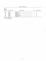
Figure 1. Sheet 5 of 5
Figure
& Index
Number
1-74
- 75
- 76
-77
-78
Part Number
120382
37113
34929
37266
37683
37013
34932
37778
Description
LOCKWASHER
. •. ••. •••••••••••. ••••. . ••. .
DRIVE SPROCKET ASSEMBLY (See figure 9) •.
DRIVE SPROCKET ASSEMBLY (See figure 9) .•
GAS CAP AND INDICA TOR ASSEMBLY
(See figure 10)
GAS CAP ASSEMBLY (See figure 10)
••.. .•.•
MAIN FRAME ASSEMBLY
. •. ••. •••••. . •. .
MAIN FRAME ASSEMBLY
•••••••••. ••••••
SPACER
•••. •••••••. •. •••. ••••••••••
Qty
2
1
1
1
1
1
1
1
Model Code
A
B
A
B
A
B
A - MK IV (SD15P10A)
B - MK V (SD18E20A)
c
5
)
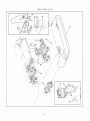
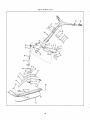
Figure 2. Sheet 1 01 3
43
)
)
6
c
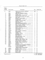
Figure 2. Sheet 2 of 3
Figure
& Index
Number
2-
Part Number
35016
34985
-1
-2
-3
-4
-5
-6
-7
-8
-9
-10
-11
- 12
r
L
-13
-14
-15
-16
-17
-18
-19
-20
-21
-22
-23
-24
-25
-26
-27
-28
-29
-30
-31
-32
-33
-34
-35
-36
34984
34271
37045
37000
132908
9000122
37006
9000122
37005
424250
37008
37007
34991
445170
37001
37003
34271
37002
37051
33610
37052
35021
124818
33647
34058
37055
437028
35027
35028
273407
35029
35023
35024
37108
37069
37111
37057
37009
9000461
35022
37471
37284
37709
37033
37031
37034
37032
Description
HOOD AND HEADLIGHT ASSEMBLY
•..•••••
(See figure 1)
HOOD AND HEADLIGHT ASSEMBLY
••. . ....
(See figure 1)
CLIP, Hood
.............•......••......
RIVET
•.............•.•........•.•....
PLATE, Hood
.........•.•..•.•.•.........
GAS LID AND HINGE ASSEMBLY
.•....••
SCREW, RD HD, 10-32 by 1/2
...........•
LOCKNUT, 10-32
................... . ... .
••••••••••.....•••••.••.
HINGE ASSEMBLY
(Consists of items 8, 9, and 10)
LOCKNUT, 10-32
......•.......•.••..••..
SPRING, Flat
•.• .•.•.••
PIN, 1/8 IN. DIA by 7/8
............... .
...••••.•.••••••.•.•.••.•..•
HINGE, Upper
HINGE, Lower
.••••••.•.
ESCUTCHEON, Gas cover
•.....•••••..•.•
NUT, Spring, 3/16
.•.......•.......•..•.••
GAS LID ASSEMBLY
................... .
(Consists of items 13, 14, and 15)
BRACKET, Support ..•.•.•.••.•••.•.•••••••
RIVET
.••.•.••••••.••••••••.•.•.••....
GAS LID
•••.••••••.•••••••••••••••.••...
RUBBER BUMPER, Gas lid
•..•.•.•••.•••..
CLIP, Wiring harness
•••••••.•••••••••
HEADLIGHT ASSEMBLY
• o.
HEADLIGHT ASSEMBLY
••.• o.
JAM NUT, Hex HD, 1/4-20
.............. ..
SPACER
•.•.•.•.•.•.•..••••.••.••.•.••.•
LOCKNUT, 1/4-20
....................... .
COVER ASSEMBLY, Headlight
.••.•..••.••
SCREW, PAN HD, 8-32 by 1-1/4 ••••.•.•••••
SHAFT, Pivot
.•••.•••••••••••••••••••••.•
SHAFT, Spring ..•••....•••••
SCREW, Truss HD, 8-32 by 3/8
•••••.••••••
SPRING, Extension
..•••••••.•••••• o . o • • • • •
BRACKET, RH •.•
BRACKET, LH •••.••.••••••••••
o.
HARNESS, Hood
.....
HARNESS, Hood
........•........••.....
HEADLIGHT
• •••••••••
HEADLIGHT
.•••.
HOUSING ASSEMBLY
.....
RIVNUT, 8-32
••
HOUSrnG
............................•...
GROMMET, Air duct
.................. ..
Am DUCT, Hood
••••••••••••••
Am DUCT, Hood
••••••••••••••••••••••••
TRIM STRIP, RH
•
TRIM STRIP, RH
•••.•
TRIM STRIP, LH
•
TRIlVI STRIP, LH
....................... .
0
•••••••••••••••••
0
•••••••••••••••••
0
0
••••••••••••
0
0
0
••••••
0
•••••••••••••••••
0
•••••
0
•••
0
7
0
0
0"
0
•••••••••••••••••
0
•
•••••••••••••••••
0
•
0
.............
0
0
0
•••••••••
••
•
••••••••••••••••••
••
0
0
0
0
0
0
•••
•••••••••
•••••••••••••
0
0
••
0
0
•••••••
•
0
••
0
•
••••••••
0
•••••••
•••••••••••
0
0
0
0
.
0
•••••••••
•••••••••••••
Qty
Model Code
REF
A
REF
B
1
3
1
1
2
2
1
2
1
2
1
1
1
4
1
1
4
1
2
3
1
1
A
B
4
2
4
1
2
1
1
4
2
1
1
1
1
1
1
1
2
A
B
A
B
1
1
1
1
1
1
A
B
A
B
1
A
1
B
A - MK IV (SD15PIOA)
B - MK V (SD18E20A)
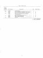
Figure 2. Sheet 3 01 3
Figure
& Index
Number
2 - 37
-38
-39
- 40
-41
- 42
- 43
- 44
- 45
-46
- 47
- 48
-49
-50
- 51
Part Number
125680
9000462
34992
445170
35011
34271
35017
34986
34989
34271
35005
9000123
34983
37591
37080
35000
37081
35001
Description
SCREW, Truss, HD, 1/4-20 by 5/8
••.•.•.•
RIVNUT, 1/4-20
.•••.•.•••••••••••••••••
ESCUTCHEON, Side
•••••••••••••••.••••
NUT, Spring
.•.•.•••••• • •..•... .. .••.•.•
STRIKE
•.••••.•••.••••••.••.• •.• •.•••••
RIVET
.•.•....•......• •.......•••. ....
HOOD
...••.......•.••.•...............•..
HOOD
•••••..• .•.•..•...•.•.... ...•.•.•...
CATCH, Hood
......•.....•.•.••..••......
RIVET
•.•••••••••••••••••••.•.••••••••
GUIDE, Hood
••..••••••.••.•.•..••.•.••..
LOCKNUT, 1/4 - 28
....................... .
SPACER
....••.••••.•.•••.•.•........•..
COVER, Bumper
•••••••. ••••••..•.•••.•.
BUMPER ASSEMBLY, RH (See figure 1)
BUMPER ASSEMBLY, RH (See figure 1)
BUMPER ASSEMBLY, LH (See figure 1)
BUMPER ASSEMBLY, LH (See figure 1)
Qty
7
7
2
6
2
4
1
1
2
4
6
6
6
Model Code
A
B
1
REF
REF
REF
REF
A
B
A
B
A - MK IV (SDI5PI0A)
B - MK V (SD18E20A)
8
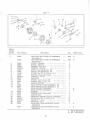
Figure 3. Sheet J of 5
c
Figure
& Index
Number
3-
Part Number
37650
37707
-1
-2
-3
-4
-5
-6
-7
-8
-9
-10
-11
-12
-13
-14
-15
-16
-17
-18
-19
-20
-21
-22
-23
-24
-25
-26
-27
-28
-29
-30
-31
-32
-33
-34
37040
34976
33320
181650
2177730251
9000125
37041
34942
181641
21777
9000125
30081
124925
37042
34943
34949
181579
147579
34688
34694
34689
9000123
37231
32185
37159
37149
32286
34946
37166
37451
37167
37168
37137
37448
37136
9000302
147579
9000123
37169
34993
37133
37067
37035
181576
147579
Description
CONSOLES AND STEERING ASSEMBLY
(See figure 1)
CONSOLES AND STEERING ASSEMBLY
(See figure 1)
STEERING LINKAGE ASSEMBLY
. •. ••. . •
STEERING LINKAGE ASSEMBLY
....••..
ARM, Spindle
•. •. •. •. •••••••••••. ••. . . . . •
BOLT, Hex HD, 3/8-24 by 2-1/2 .•.•••...•.•
SPACER
.••••••••.••••••••••.•••••••••••
SPACER
• .• .•. .• • .• . •• • .•• •• ... • .• .•.••.
LOCKNUT, 3/8-24
..••..•.•.•..•••••.••••.
TIE ROD ASSEMBLY
•••••••••..••• •..••.
TIE ROD ASSEMBLY
••••••••••••••••••••
BOLT, Hex HD, 3/8-24 by 1-3/8 ••.•.•.•.•..
SPACER
.•••.•••.•••.•....•.•.•• ••.• •.••
LOCKNUT, 3/8-24
.•• . . . •• •• . •••• • ••• •••.•
ROD END
•.•••••••••.• . •••••.••••••••••••
JAM NUT, Hex, 3/8-24
.••••••••••••• •••• ..
TIE ROD
. •.•••••.•••• ••••••••••• .• ••••.•
TIE ROD
..•••••.•.....•. ••• .•.••••.••••.
STEERING COLUMN ASSEMBLY ..•.••.•.••.
BOLT, Hex HD, 1/4-28 by 2 ...•.•.•••••••••
WASHER, Plain, 1/4
. . •. •. . . •. . . . . . . ••••
U-STRAP
••••.••..•••.•••..••••••..•••••.
WEARPLATE
. •..•..•••.•••. .•.••••••••••
WEARPLATE
••••••.•••.••..•.•. .•• .•••..
LOCKNUT, 1/4-28
.•.•...•....•.•.•••• ....
GRIP, Hand
. •. •. •. . ••. • • ••. ••. . . • • • • •••
THUMB CONTROL ASSEMBLY
...•..•...••
BRAKE CONTROL ASSEMBLY
. . . . . . . •••. .
THROTTLE CABLE, HOUSING AND
.••.•...
BOOT ASSEMBLY
CLIP, Wire
••..•..••••••.. . •.••••••••••
STEERING HANDLE AND COLUMN
••••••••
ASSEMBLY
CONSOLE DOOR ASSEMBLY
CONSOLE DOOR ASSEMBLY
RET AINER, Console door
•••••.••••••••.•
FASTENER, 1/4 turn
•...••••••••.•••••••
DOOR, Console
.•.••.••••••••••.•••••••
DOOR, Console
•••••••.••••••••.•••..••
CONSOLE TONGUE ASSEMBLY
•.••.•••••••
SCREW, Truss HD, 1/4-28 by 5/8
•.••••••
WASHER, Plain
.••••.••••••••.•.•••••••
LOCKNUT, 1/4-28
.••••••••••••••••••.•••.
CLIP-ON RECEPTACLE, Console door
DECAL, Console tongue •••••••.••••••••••• .
CONSOLE TONGUE •••••••••••••••••••.••••
MINI-CONSOLE ASSEMBLY •••••••••.••••••
MINI-CONSOLE ASSEMBLY ......••••••••••
BOLT, Hex HD, 1/4-28 by 1-5/8 ••.••••••.••
WASHER, Plain
..•..•.•......•.•.•..•..
Qty
Model Code
REF
A
REF
B
2
2
2
2
4
2
2
2
2
2
4
2
4
4
2
2
1
2
4
1
1
1
2
2
2
1
1
A
B
A
B
A
B
2
1
1
1
1
A
B
1
1
1
A
B
1
4
4
4
1
1
1
1
1
A
B
2
2
A - MK IV (SDI5PI0A)
B - MK V (SDI8E20A)
9
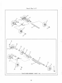
Figure 3 . Sh ee t 2 of 5
)
)
)
10
C
Figure 3. Sheet 3 01 5
Figure
& Index
Number
3-35
-36
-37
-38
-39
-40
-41
-42
-43
-44
-45
-46
-47
-48
-49
r
'--
-50
-51
-52
-53
-54
-55
-56
-57
-58
-59
-60
-61
-62
-63
-64
-65
-66
-67
-68
-69
-70
-71
-72
-73
-74
-75
-76
-77
Part Number
33808
9000123
37374
37036
34271
37135
37072
37075
37076
1500480
34997
34996
37230
1500477
34998
35044
37286
37285
37037
120612
9000122
37039
37038
37432
436756
446143
9000122
37077
137258
37124
34945
30149
33753
33756
37222
34916
37245
187044
9000125
37226
34920
37411
144518
33748
28762
33732
37412
181639
274517
9000125
34969
33731
Description
WASHER, Formed
..•••.•.•.•.••...•••.•••
LOCKNUT, 1/4-28
.•..••..••..•.••.••.•...
BAR, Console support
•...•.•....•.••..•••
BAR, Console support
.•...•.....•.•...•..
RIVET
...•.•........•.•••••....•...•.•
PLATE, Console back-up
•....•.....•....
SWITCH, Key
•.•••..•.•.•...•.•...•...•.•
SWITCH, Toggle, 2-position ••••...•.•....••
SWITCH, Toggle, 3-position .•.•.•....•.....
BOOT, Rubber, toggle switch
••.•.•••.•.•
DECAL, LH
.••...•.•.•••••...•..••••.••
DECAL, LH
•••••••••••••••.•••• ,••••••••
CONTROL, Choke
..•.•.•.••••.•••••....••
LIGHTER, Cigarette
..•••••••••.•.•••...
DECAL, RH
•..•.•.•••.•.•••....••......
MINI-CONSOLE
..•.•..•.....•.•.••.....
AIR DUCT, LH .•••.•••••••••••••••••••••••
AIR DUCT, RH ....•....•...•......••••••••
BRACKET, Console
.•..•••.••..•.•..•.•
SCREW, Flat HD, 10-32 by 5/8
•.•...•.•.••
LOCKNUT, 10-32
•.•.•.•.••••.•.•.•...•••
ROLL BAR
.••.•....••.•••••.•••.•.•••.
ROLL BAR
.•........••....•...•...•.•.
BRACKET, Flasher
.•...•.....•.•.•...•
SCREW, Pan HD, 10-32 by 1-1/2
......•.
WASHER, Plain
..•.•.....••..••.•..•...
LOCKNUT, 10-32
..••.•....•.....•.....•.
FLASHER
.............•.•........•..•..••
COTTER PIN, 3/16 by 1-3/4
••.•.•.•....
WASHER, steering column
......•.•....•..
BUSHING, Steering column
•..•...•..•••...
SPRING, Spindle
.......••.....••.•.•..•.
BEARING, Plain
.........•...•.•...•.•.•
BEARING, Flange
•.•.•.•...•.......•.•..•
SPINDLE
.••.............•.••....•.•..•.•
SKI AND SPRING ASSEMBLY (See figure 1) .•.•
SKI AND SPRING ASSEMBLY (See figure 1) .•••
SCREW, Hex HD, 3/8-24 by 3-1/2
•••.••••
LOCKNUT, 3/8-24
......••.•.•••.••.••..••
PAD, Spindle
..••.•.•..••.•..•.•.....••••
SKI SPRING ASSEMBLY .••••....••....•..••
SKI SPRING ASSEMBLY •••..•••••••••.••...
COTTER PIN
.••...•••..••...••.••••••••.
PIVOT PIN, Spring .•.•.•..••..••..••.••..•
PIN', Pivot ............................... .
BRACKET ASSEMBLY, Spring mounting
BRACKET ASSEMBLY, Spring mounting
.•.•...•
SCREW, Hex HD, 3/8-24 by 1-1/4
WASHER, Flat, 3/8
•.•.•.•.•••••••.•.•.
LOCKNUT, 3/8-24
....•.••••.•.•.••..•.•.•
BUMPER ASSEMBLY
.•.•...•.••.••...•••
LEAF SPRING, Top
....••.•.•••.•.•.•..
Qty
Model Code
2
2
2
A
2
B
4
2
1
1
1
B
B
2
1
B
A
1
B
1
1
1
B
1
1
1
1
2
2
1
A
1
1
1
1
1
1
B
B
B
B
B
B
2
2
1
2
2
2
2
REF
REF
2
2
2
2
2
4
2
2
2
2
4
4
4
A
B
A
B
A
B
2
2
A - MK IV (SD15P10A)
B - MK V (SD18E20A)
11
)
F,gure
·
3. Sheet 4 of 5
/i
51
32
49
53
36
J2
\
C
Figure 3. Sheet 5 of 5
Figure
& Index
Number
3-78
-79
-80
-81
-82
-83
-84
-85
-86
Part Number
33730
37249
33746
34917
37246
34919
9413314
34918
37247
181620
120394
9000124
Description
LEAF SPRING, Middle
. . . . ••. ••. . . . . . . . . ••
LEAF SPRING, Main
.•••..•.•.•.•. •..•••
WEAR PLATE, Ski
..•• .• .•..... .....•.•...
SKI AND WEAR ROD ASSEMBLY ...•...•...•
SKI AND WEAR ROD ASSEMBLY • . . . . . . . . . . .
WEAR ROD ASSEMBLY, Ski • . . . . . . • . . . • . . • .
LOCKNUT, 1/4-20
........••..•••.•.•...•.
SKI ASSEMBLY
.•.........•....•.•.....
SKI ASSEMBLY
. • . •. . . . . . . . . . •. • . • . . . • .
SCREW, Hex HD, 5/16-24 by 2
••••..•.....
WASHER, Plain
.................. ......
LOCKNUT, 5/16-24
•.•••.•........•.•..
Qty
2
2
2
2
2
2
2
2
2
2
4
2
Model Code
A
B
A
B
A - MK N (SD15P10A)
B - MK V (SD18E20A).
J3
Figure 4. Sheet 1 of 2
)
13
6.
\
\
35
\
\
\
\
\
\
\
\
\
' VLk.~;;""--
\
\/
,i
)
J4
c
Figure 4. Sheet 2 of 2
Figure
& Index
Number
4-
37809
37764
-1
-2
-3
-4
-5
-6
-7
-8
-9
-10
-11
-12
-13
-14
-15
-16
-17
-18
-19
-20
-21
-22
-23
-24
-25
-26
-27
-28
-29
-30
-31
-32
-33
-34
-35
Description
Part Number
37165
144815
33611
144815
33610
37147
37146
181003
9416904
9000123
37257
134179
9000551
37156
37155
37152
34024
37651
33584
37078
37388
37278
37395
37392
37394
37373
37644
9000121
37237
37646
422420
9414920
37647
9000123
37157
37158
37210
37205
128157
30228
REAR CONSOLE, SEAT AND TOOL BOX
ASSEMBLY (See figure 1)
REAR CONSOLE, SEAT AND TOOL BOX
ASSEMBLY (See figure 1)
SEAT
.••.•.••••.••.••...••.•.....•...•..•
SCREW, PAN HD, Self-tapping, 8 by 5/8
LATCH, Spring
•••.•••••••.••.•••••••.•
SCREW, PAN HD, Self-tapping, 8 by 5/8
CLIP, Wiring
..•••.•••••.•.•.•.••••' .••••.
REAR CONSOLE ASSEMBLY
•.••••.•.•.•
REAR CONSOLE ASSEMBLY
•..•••...•.•
BOLT, HexHD, 1/4-28 by 5/8
••••••.•.•••
WASHER, Flat ...•.•.•••••.••••.••••••...•
LOCKNUT, 1/4-28
.•••••••.••.•..••.••••.•
COVER, Taillight lens
•••••••••.•••.•....•
SCREW, Machine oval HD, 6-32 by 3/4
NUT, Molly jack, 6-32
•••.•••.•••.••..•••.
LE NS, Taillight
........•••••.••••.•..•.
BRACKET AND SOCKET ASSEMBLY .••.••••
BRACKET AND SOCKET ASSEMBLY ..•.••••
RI'VET
.•••.•..•..••...•........•..•...
RIVET BURR
•..•••.•••••••••.•.••.•.•.•.
BULB, Taillight
.•••••.••••.••.••••.••••
BULB, Taillight
•....•••...•••....•.•.••
TIE, Cable
••••.•.••••••••••.•••••.•.••
WffiE, Taillight ground
•••••.•••.•••.•••••.
WffiE, Taillight
••.••••••••.••••••••••••
WffiE, Taillight, left-turn signal •••••.••.•.•
WffiE, Taillight, right-turn signal
••.•••••
STUD, Rear console, 8-32 by 5/8
•.••.•••
WASHER, Rear console
.•••••.•.•••.••.••••
LOCKNUT, 8-32
••.••.••.•••.•.••....•••
CONSOLE, Rear
••••...•••••••••..••••..
BUMP ER, Kickstand
.•••.••..••••.•.•.••
SCREW, RD HD, 1/4-28 by 1-1/4
..••••••
WASHER, Plain
.••..•...••••.•.•.•••••.
SPACER
••.•.•....••..•.•••..•...•••.•••
LOCKNUT, 1/4-28
••••••.•••.••.••.•••••••
BRACKET, Rear console, RH
.•.•.•••..•.
BRACKET, Rear console, LH
.••••••.••••
TOOL BOX
..•..•...•.....•.•••••••.•.•
TOOL BOX
..•..••••••••••••••.•.•••.••
GROMMET, Rubber
•.•.••••••..•.••.•.•
FOOT PAD
••••••••••••••••••••••••••••
Qty
Model Code
REF
A
REF
B
1
6
2
4
2
1
1
A
B
3
6
3
1
4
4
1
2
2
4
2
2
2
1
1
1
1
1
A
B
A
B
B
B
3
3
3
1
2
2
2
2
2
1
1
1
A
1
2
B
2
A - MK IV (SD15P10A)
B - MK V (SD18E20A)
--15
)
Figure 5. Sheet 1 of 2
i"--~_3
I
I
't-i()
35
)
DETAIL A
\
)
16
c
Figure 5. Sheet 201 3
Figure
& Index
Number
5-1
-2
-3
-4
-5
-6
-7
-8
-9
-10
-11
-12
-13
- 14
-15
-16
-17
-18
-19
-20
-21
-22
-23
-24
-25
-26
-27
-28
-29
-30
-31
- 32
-33
-34
-35
-36
-37
-38
-39
-40
-41
-42
-43
-44
Part Number
37120
37181
2791
37598
30489
30270
37225
33859
420998
1500932
37666
37258
37402
37399
37171
33946
125793
37105
180147
120383
37188
9000323
37189
120393
9000124
37400
33768
37699
37187
32588
37183
34032
181595
120393
9000124
37173
37735
*1002400
132908
9000122
32511
37353
38462
37620
37619
37617
37618
Description
ENGINE AND SUPPORT ASSEMBLY
•.•.•.••
(See figure 1)
PIPE, Engine exhaust
..••••••••••.••••...
CLIP
..... .............. ................ .
BRACKET, Throttle
•..•...•...•..•...••
CLAMP, Hose
•.••...•..•.•••••..•••.•.•••
IMPULSE LINE, 3/16 by 5/16 by 7
.....•••
WIRING CONNECTIONS, L295 engine .....•..
COVER, Air intake ....•.....••...•.•......
SCREW, RD HD, 1/4-20 by 1-1/2
.••••.••
CLIP, Cable
.......... .. ................ .
BRACKET, Choke control
..••.•.•..•...•.
CARBURETOR •..••.••....••...••••.•.•.•.
HOOK, Spring
.•.•.•.•.•••.•••••..••••..••
EXTENSION SPRING, Throttle
•.••.•••••••
DRIVE CLUTCH ASSEMBLY (See detail A) ••••
BOLT, Clutch adaptor
..•..••..•••.•.••.••
LOCKWASHER, 13/16
••••.••••••••••.•.••
ENGINE, JLO 295
.•.•.•.•.•.•..•..•..••••
BOLT, Hex HD, 7/16-14 by 1-1/4
••••••••
LOCKWASHER, 7/16
••••••••••••••••••••
BASE, E'ngine
••••••.••.•••••••••••••.••••
BOLT, Carriage, 5/16-24 by 1
•.••••.•••••
BAR WASHER
..................•..•......
WASHER, Plain
••.•••.•••.•••••••••••••
LOCKNUT, 5/16-24
••••••••.••••••.•.••
RET AINER, Spring •.•...•..•.•.•..•.•••.••
SHOCKMOUNT •••••.•.•.•.•.•.•.•.•.••••.•
PAD, Shockmount
•.••.•.•••••••••.•••.•••
MOUNTING STRAP .•.••.•••••.••••.•••••••
CLAMP, Flexible tube
•••••••..•...••.••••
EXHAUST TUBE, Flexible
••.•••••••••.••.
BAND ASSEMBLY, Mounting
•.••••.••.••
SCREW, Hex HD, 5/16-24 by 3/4
•••.••..
WASHER, Plain, 11/32 by 11/16 ••••••.•..••
LOCKNUT, 5/16-24
•..••..••.•.••.•.•.•
MUFFLER •..•.•.•••.•.•.•••••••.•.•••••••
CLUTCH GUARD AND DECAL ASSEMBLY
CLUTCH GUARD KIT (Replaces items 36
through 40)
SCREW, RD HD, 10-32 by 1/2
.••••.••••••
LOCKNUT, 10-32
••.•••.•.••.••••••••••••
SPRING PLATE, Clutch guard
•••.•••••.••
DECAL, Safety ....•.•..••••••••••••.•.••••
GUARD, Cilltch
....................... .
WASHER, Safety
..•••••.••••••••••••••••
RrnG'r RetainiIlg
.•.•.•••••••••.••••...••
SPACER
............................... .
SCREW KIT (Consists of gasket,
•••••••••••
Qty
Model Code
REF
A
1
1
1
2
1
A
A
A
A
A
1
A
1
A
3
A
1
1
1
1
A
A
A
A
1
A
1
1
A
A
1
1
4
A
A
A
4
A
1
A
4
2
4
4
A
A
A
A
1
A
1
2
2
2
1
A
A
A
A
A
1
A
2
4
2
A
A
A
1
A
1
1
A
A
2
2
1
A
A
A
1
1
1
A
A
A
1
A
1
1
A
A
3 washers and bolts)
A - MK IV (SD15PIOA)
B - MK V (SDI8E20A) '
*Replacement Kit
J7
)
fjgw .. 5. Sheet 3 of 3
Figure
& Index
Number
5-45
-46
-47
-48
-49
-50
Description
Part Number
37616
37615
37624
37623
37622
37621
RA.MP PLATE
••••••••••••••••••••••••••••
SPIDER
............................... .
ROLLER KIT
........................... .
SPRIN'G KIT
.••••...••.•.•.••.••••.•.•••
MOVABLE FACE
.•••.•.•••••••••••••••••
FIXED FACE
................•...........
Qty
1
1
1
1
1
1
Model Code
A
A
A
A
A
A
A - MK IV (SD15PIOA)
B - MK V (SD18E20A)
J
J
18
c
figure 6. Sheet J of 3
Figure
& Index
Number
6-1
-2
-3
-4
-5
-6
-7
-8
-9
-10
-11
-12
-13
-14
-15
-16
-17
-18
-19
-20
-21
- 22
-23
-24
-25
-26
-27
-28
-29
-30
-31
-32
- 33
-34
-35
-36
-37
-38
-39
-40
-41
-42
-42A
-43
Part Number
34927
37101
37099
30489
30270
37131
1500932
37666
420991
37258
37191
37190
37403
37399
37130
189348
37383
37054
37079
180175
120384
37118
9000323
37126
120393
9000124
37401
33768
37699
37438
34980
32588
37142
37143
34032
181595
120393
9000124
37095
33735
37215
*1002400
132908
9000122
32511
38462
37353
37944
Description
ENGINE AND SUPPORT ASSEMBLY
(See figure 1)
EXHAUST MANIFOLD, 5 degree
EXHAUST MANIFOLD, 45 degree
CLAMP, Hose
IMPULSE LINE, 3/16 by 5/16 7
WIRING CONNECTIONS, 493/2 engine
CLIP, Cable
BRACKET, ,Choke control
..
SCREW, RD HD, 1/4- 20 by 1/2
CARBURETOR
GASKET, Carburetor flange
BRACKET, Throttle
HOOK, Spring
EXTENSION SPRING, Throttle
DRIVE CLUTCH ASSEMBLY (See detail A)
BOLT, Hex HD, 1/2-20 by 5
CABLE, Battery to ground
STARTING MOTOR ASSEMBLY
ENGINE, Hirth 493
BOLT, Hex HD, 1/2-13 by 1-1/4
LOCKWAsHER, 1/2
BASE, Engine
BOLT, Carriage, 5/16-24 by 1
BAR WASHER
.
WASHER, Plain
LOCKNUT, 5/16-24
RET AINER, Spring
SHOCKMOUNT .
PAD, Shock mount
MOUNTING STRAP, Front
MOUNTING STRAP
CLAMP, Flexible tube
.
EXHAUST TUBE, Flexible, long
EXHAUST TUBE, Flexible, short
BAND ASSEMBLY, Mounting
SCREW, Hex HD, 5/16-24 by 3/4
WASHER, Plain, 11/32 by 11/16
LOCKNUT, 5/16-24
MUFFLER
CLUTCH GUARD AND DECAL ASSEMBLY
CLUTCH GUARD ASSEMBLY
CLUTCH GUARD KIT
(Replaces items 39 through 42A)
SCREW, RD HD, 10-32 by 1/2
LOCKNUT, 10-32
SPRING PLATE, Clutch guard
GUARD, Clutch
DECAL, Safety •...........................
LOCK P I.A. TE
........................... .
0
0
••
000
•••
0
0
0
0
0
0
0
0
0
•
000.0000
0
0
•
0
•••
0
••
0
0
0
0
•
0
•••
•
0
0
0
0
0
0
0
•
00.0.0000000
0
00.0.000000.000000
0
0
0
0
0
0
0
0
0
0
0
0
0
0
••
0
00000000
0
0
0
0
0
0
0
0
0
00000000.
000
0
0
0
0
0
0
0
0
0
0
0
0
0
0
0
0
0
0
0
0
0
0
0
0
0
•
0
0
0
0
0
0
•
0
0
0
0
0
0
0
0
0
0
0
0
0
0
0
0
0
0
0
0
0000000000000000000000000000
000000000000
000.
0000000000000000
0000000000000000
000000000000
000000000000000000000000
000000000000
0
•
0
0
0
0
0
0
0
0
0
0
0
0
0
0
•
0
0
0
0
0
0
0
0
0
0
0
0
•
0
0
0
0
0
0
0
0
00
0
0
0
•
0
0
0
0
000
0
0
0
0
0
0
00
0
000000000000000000000.00000
0
0
0
0
00
0
0
00
0
0
00
0
0
0
0
0
0
•
000
0
00
0
0
0
0
0
0
0
0
0
0
0
0
0
0
0
•
0
0
0
0
0000000000.
000000.000000
0
•
0
•
0
0
•
0
0
0
0
0
0
0
0
0
0
00.00000.
0
0
0
0
0
0
000.0.000
0
0
0
0
0
0
0
0
0
0
•
0
0
0
0
0
0
0
0
0
•
0
0
.000000000000000.000
Qty
Model Code
REF
B
1
1
B
B
2
B
1
1
1
1
B
B
B
B
3
B
1
1
1
1
1
1
1
1
1
1
B
B
B
B
B
B
B
B
B
B
4
B
4
B
1
B
4
2
B
B
4
B
4
B
1
B
4
B
4
B
1
1
B
B
4
B
1
1
1
B
B
B
2
4
2
B
B
B
1
1
1
1
B
B
B
B
000000000000
2
B
.0000000000.00000.0.0000
2
B
1
1
1
1
B
B
B
B
0
0
0
0
0
0
0
0
•
0
0
0
0
0
0
0
0
0
0
000000000000
.0000000
000000000000
0
0
000000
00000.000000
0000000.00000
000000000.0000.
0
0
0
0
0
0
0
0
000000
0.00000000
0000
000000000000
0000000000000.000000
00000.00000.
00
0
0
0
0
0
0
000
0
0
0
0
0
0
••
0
0
0
0
0
A - MK IV (SD15PI0A)
B - MK V (SDI8E20A)
*Replacement Kit
19
Figure 6. Sheet 2 of 3
J
DETAIL A
38
30
55
...
SEE
VIEW A
--- ~
68
67
~----
VIEW A _ _ _ _---I
J
20
Figure 6. Shee' 3 01 3
C
Figure
& Index
Number
,,-...
'-
Part Number
6-44
-45
-46
-47
-48
-49
-50
-51
-52
-53
-54
-55
-56
-57
-58
-59
37936
37720
37719
37718
37717
37631
37716
37715
37714
37713
37712
33979
37064
37065
37062
9000123
37765
-60
-61
-62
34015
37410
37071
37094
34014
37410
37387
37385
436695
9000121
37386
37382
37381
133427
9000126
37377
181003
900012.3
34029
436750
121801
9000122
138538
37058
-63
-64
-65
-66
-67
-68
-69
-70
-71
-72
-73
-74
-75
-76
-77
-78
-79
-80
-81
-82
Qty
Description
....................................
· ...................
...........................
·...............................
·...........................
·...........
·...........................
·...................
·.......................
·...............
·...................
·.......
·.......
· ...........
·.......................
NUT
RETAINING WASHER
RAMP PLATE
·
SPIDER
ROLLER ARM ASSEMBLY, Kit
SPRING KIT
MOVABLE FACE ASSEMBLY
LINER, Spline
WASHER, Idler bearing
BEARING', Idler
FIXED FACE ASSEMBLY
STORAGE BATTERY
BATTERY HOLDDOWN ROD, Long
BATTERY HOLDDOWN ROD, Short
BATTERY HOLDD OWN STRAP
LOCKNUT, 1/4-28
BATTERY SUPPORT AND ELECTRICAL
ASSEMBLY (See figure 1)
CABLE ASSEMBLY, To starter
TUBING
SLED HARNESS
ELECTRICAL PANEL ASSEMBLY
CABLE ASSEMBLY, Battery to solenoid
TUBING
·
JUMPER LEAD
RECTIFIER ASSEMBLY
SCREW, PAN HD, 8-32 by 1/2
LOC KNYT , 8-32
HEAT SHIELD, Rectifier
FUSE, 15 amp
FUSE HOLDER
SCREW, Flat HD, 6-32 by 7/16
LOCKNUT, 6-32
RESISTOR, Fixed
BOLT, Hex HD, 1/4-28 by 5/8
LOCKNUT, 1/4-28
•••••••••.•.••.•••••••••
SOLENOID, Electric start
SCREW, PAN HD, 10-32 by 1/2
LOCKWASHER, Internal tooth, No. 10
LOCKNUT, 10-32
LOCKWASHER, Internal tooth, 5/16
BATTERY SUPPORT, Weldment
•
• • • • • • • • o6 • •
·...........
·................................
·.......................
·.......
...............................
· .......................
· ...................
·...........
·.......................
· ...............
·...........................
·...........................
·...........
·.......................
·.......................
·...........
·...............
·...........
·.......................
·.......
·...........
1
1
1
Model Code
1
1
1
6
1
1
1
1
1
1
1
2
REF
B
B
B
B
B
B
B
B
B
B
B
B
B
B
B
B
B
1
1
1
1
1
1
1
1
2
2
1
1
1
1
1
1
1
1
1
2
1
2
2
1
B
B
B
B
B
B
B
B
B
B
B
B
B
B
B
B
B
B
B
B
B
B
B
B
1
A - MK IV (SD15PI0A)
B - MK V (SD18E20A)
2,1/22
]
c
Figure 7
Figure
& Index
Number
7-
Part Number
37203
34924
-1
-2
-3
-4
-5
-6
-7
-8
-9
- 10
- 11
-12
- 13
- 14
- 15
- 16
- 17
- 18
- 19
- 20
-21
- 22
- 23
32266
32265
456145
9000124
34683
34684
181651
33705
9000125
32237
33356
33357
706
33346
33347
37199
37196
33417
37197
30079
37192
181566
9000123
37144
37200
37198
Description
TRACTION BELT TAKE - UP ASSEMBLY
(Se e figure 1)
TRACTION BELT TAKE - UP ASSEMBLY
(See figure 1)
SCREW, Adjusting
. . . . . •. •. •. •. . . . . ••. . . ••
BLOCK, Adjusting
••. •. . . •. . •. . . •. ••••. •••
WASHER, Flat,. 5/16
. .•. .. . .•• •. . • ••. • .•
LOCKNUT, 5/16-24
. . . . ••••••. •••. . . •. •
ANGLE, Belt adjustment, RH
. . . •. . ••. ••.
ANGLE, Belt adjustment, LH
. . •• ••• .. ••.
SCREW, Hex HD, 3/8-24 by 2-3/4
.••.••.•
SPACER, Rear support arm
..•••••.•. ••.•..
LOCKNUT, 3/8-24
. . . •. . . •. •. . . •. ••••. •. •.
RETAINER
.•••.••.•...•.•.•...•.•.....
SPRING, Rear torsion, RH
. . . . . . ••••. . . . . •
SPRING, Rear torsion, LH
••. •••. . •. . ••. •.
GREASE FITTING
. • •• •• •. ••• . . . • •• • . . • . • .
REAR SUPPORT ARM ASSEMBLY, RH
REAR SUPPORT ARM ASSEMBLY, LH
REAR SUPPORT ASSEMBLY
...•.. • •.••.
REAR SUPPORT ASSEMBLY
...•.•.••.•.
B EARING
.•••.•.. .... .•••••••..•...•••.••
CUPPED PLUG, Rear shaft
•.••.•••.• •.... .
GREASE SEAL . • . • • • • • • . • . . . • • • • • • • . . . • . . .
SPROCKET SUPPORT PLATE ASSEMBLY ..• .
SCREW, Hex HD, 114-28 by 3/ 4
..••••••••••
LOCKNUT, 114-28
. .....•.. • . • ••.•.•.• • •••
SPROCKET, Idler
•. . . • . ••• •• •• •• •• • •• •• • •
REAR SHAFT AND SPROCKET PLATE
ASSEMBLY
REAR SHAFT AND SPROCKET PLATE
ASSEMBLY
Qty
Mod el Code
RE F
A
REF
B
2
2
2
2
1
1
2
2
2
2
1
1
2
1
1
1
A
B
1
2
2
2
2
18
18
2
1
A
1
B
A - MK IV (SDI5P I OA)
B - MK V (SDI8E20A)
23
L
Figure 8 . 5nee'
1 of 2
)
)5
"- _,;
~~
21 .----
19
12
~ ~ ~-----~
""
10
'"
'
20
_ _ _ _ _ _-===~F~ROOINT BOGIE A5SEMBLY- MARK V only
24
]
c
Figure 8. Sheet 2 of 2
Figure
& Index
Number
8-1
-2
Part Number
37083
34901
33712
33712
33711
33711
37085
34902
-3
-4
-5
-6
33713
33713
9000393
9000393
37086
34907
37084
33754
37088
34903
-7
-8
-9
-10
-11
- 12
- 13
-14
- 15
-16
-17
-18
-19
-20
- 21
33713
33713
9000393
9000393
37089
34908
34904
33712
33711
33713
9000393
33909
33907
33754
34906
34905
34903
33713
9000393
34908
Description
BOGIE ASSEMBLY (See figure 1) •.•.•••.••••
BOGIE ASSEMBLY, Middle and rear
.•••.•••
(See figure 1)
TORSION SPRING, Bogie, RH
TORSION SPRING, Bogie, RH
TORSION SPRING, Bogie, LH
TORSION SPRING, Bogie, LH
BOGIE WHEEL AND SUPPORT
ASSEMBLY - HALF
BOGIE WHEEL AND SUPPORT
ASSEMBLY - HALF
WHEEL, Bogie •.••.•.•••.•.•....•.••..••••
WHEEL, Bogie •.•.•.••••••••••••••••••.•..
LOCKNUT, 5/8 - 18
••••••••••••••••••••••••
LOCKNUT, 5/8 - 18
. . .•.••.••.•••••••••••••
BOGIE SUPPORT ASSEMBLY - HALF
BOGIE SUPPORT ASSEMBLY - HALF
SUPPORT SHAFT, Bogie wheel
••••••••••••
SUPPORT SHAFT, Bogie wheel
•••••••.•••.
BOGIE WHEEL AND SUPPORT
•..••.•.••••
ASSEMBLY - HALF
BOGIE WHEEL AND SUPPORT
ASSEMBLY - HALF
WHEEL, Bogie •••.•••.••••••••••••••••••••
WHEEL, Bogie .••••.•.•••.•..•••••• •• ••••.
LOCKNUT, 5/8-18
•.•..••.••••••••••••••••
LOCKNUT, 5/8-18
. ..•....••.••••.••.• • .••
SUPPORT ASSEMBLY, Bogie
••.•..•..••.
SUPPORT ASSEMBLY, Bogie
.•.••.•.•.••
BOGIE ASSEMBLY, Front (See figure 1)
TORSION SPRING, Bogie, RH
.••.•••••.••
TORSION SPRING, Bogie, LH
••.••••..•••
WHEEL, Bogie .•.•.•.•.•••••.•••••••••••••
LOCKNUT, 5/8-18
•••••••••••••••••.••••••
SHAFT, Bogie axle
.•••••...•••••••••••••••
BUSH lNG, Bogie
•••••••••••.•••.•••••.••
SUPPORT SHAFT, Bogie wheel
.••••••.••••
SUPPORT ASSEMBLY, Bogie, RH
• ••• •• ••
SUPPORT ASSEMBLY, Bogie, LH
•••••.• .
BOGIE WHEEL AND SUPPORT
•••.•• • .••.•
ASSEMBLY - HALF
WHEEL, Bogie •••••••••••••••.•••••• • •.•• •
LOCKNUT, 5/8-18
••••••••••••••••••••••••
SUPPORT ASSEMBLY, Bogie
•• ••••••••••
Qty
Model Code
REF
REF
A
3
2
3
2
3
A
B
A
2
B
6
A
B
A
4
6
4
3
2
3
2
3
B
A
B
B
A
B
A
B
A
2
B
6
A
B
A
B
A
B
B
B
B
B
B
B
B
B
B
4
6
4
3
2
REF
1
1
3
2
1
4
1
1
1
1
2
2
1
B
B
B
B
B
A - MK IV (SDI5PI0A)
B - MK V (SDI8E20A)
25
Figure 9. Sheet 1 of 3
)
20
LD_E_TA_IL_ A_ _ _ _ MARK V only
_~_ _ _ __
4
. /-6
52
]
26
c
Figure 9. Sheet 2 of 3
Figure
& Index
Number
9-1
-2
-3
-4
-5
-6
-7
-8
-9
-10
-11
Part Number
37290
37292
37420
446152
37291
37140
137258
35042
35041
34629
180078
37440
37439
37115
34928
-12
-13
-14
-15
-16
-17
-18
-19
-20
-21
-22
-23
-24
-25
-26
-27
-28
-29
-30
-31
- 32
-33
-34
-35
-36
-37
-38
-39
- 40
-41
-42
37254
272726
9000125
34277
34304
119120
125250
9417098
34628
34636
147664
120393
9000124
34645
28784
272686
106751
37378
37469
181610
181608
9000124
120854
37172
34914
37170
34968
34925
37253
9000124
34826
273938
34950
34952
9417098
Description
CHAIN COVER TOP ASSEMBLY
STRAP, Chain cover
••.•.••••..•.•.•••.•
RIVET
•••...•...•..•.•...•.•.•...•.•••
WASHER, Plain, 13/64 by 15/32
•.•..••...•.
CHAIN COVER, Top
. .. .. .•....•.•..•...
ROLLER CHAIN, 35-2, 100 pitch
..•.....
COTTER PIN, 3/16 by 1-3/4
... ........ .
SPROCKET, 35-2, 45 teeth
...•....•...•••.
SPROCKET, 35-2, 44 teeth
., ..•.•..••.....
SPACER
.•.....•.•.......•.....•.•... • ••
BOLT, Hex HD, 5/16-18 by 7/8
.•••...•..•.
WASHER, Chain cover
•.•..•.•......•.•••.
SPACER, Chain cover
.•.•.•••••••.••.•...
DRIVEN CLUTCH AND MOUNTING
•••..••.
ASSEMBLY (See figure 1)
DRIVEN CLUTCH AND MOUNTING
ASSEMBLY (See figure 1)
ROD TENSIONER, Clutch
•.••... •• .•••••.
STUD, 3/8-24 by 1-1/2
................... .
LOCKNUT, 3/8-24
.••......••...• .••• ...••
SPROCKET, 35-2, 19 teeth
.•.•.••.••.••...
SPROCKET, 35-2, 21 teeth
..••..••••••.••.
COTTER PIN, 3/32 by 1-1/4
.......... ..
NUT, Slotted, 1/ 2-20
....•.•..• •..•.....•
WASHER, Flat, 17/32 by 1
•.•.•.•.•..•.•.•
SPACER
.....•...•.•.••••.••.•.•.•.•••••
CLAMP, Bearing
•••.••.•......•.••.•.•..
STUD
..•.•.••••.•.•.•••.•••••.•••••.•••••
WASHER, 11/32 by 11/16
.............. ..
LOCKNUT , 5/16-24
.................. ..
BEARING, Driven clutch
••.••••...•..••.
HUB AND DISC ASSEMBLY
•........•••••.•
LOCKNUT, 3/4-16
...................... ..
KEY, Woodruff, No.9, 3/16 by 3/4
...... ..
DISC BRAKE ASSEMBLY
..........•.....
DISC BRAKE ASSEMBLY
..•.•...•......•
BOLT, Hex HD, 5/16-24 by 1-1/4
•.•.....
BOLT, Hex HD, 5/16-24 by 1
.......... ..
LOCKNUT, 5/16-24
.................. ..
BOLT, Hex HD, 1/4-20 by 5/8
•••••••.•...
BELT, Variable speed
.................. ..
BELT, Variable speed
•..• .•• .• '" ••••.•••
DRIVEN CLUTCH AND SHAFT (See detail A) •••
DRIVEN CLUTCH AND SHAFT (See detail A) .,.
DRIVEN CLUTCH MOUNTING
••.•...•••••
WASHER, Serrated
.•.•..•.•....••••••••.••
LOCKNUT, 5/16-24
................... .
RING, Retaining
•.•.•.•..•••.••••••••••.
PIN, Spr ing
.•.•••.•.....•••••.•••••.•••
CAM, Right side
•.••...•.•••..•••.•••.••
CAM, Left side
•••••.••.•.•.•••.••••.••
WASHER, Plain, 17/32 by 1 ...•••••••...•••
Qty
Model Code
1
2
2
4
1
1
1
1
1
1
1
1
1
REF
A
B
A
REF
B
1
1
1
1
1
1
A
B
1
1
1
2
4
4
4
2
1
1
1
1
1
1
1
2
1
1
1
1
1
1
A
B
A
B
A
B
1
1
1
2
1
1
1
A - MK IV (SD15PIOA)
B - MK V (SD18E20A)
27
Figure 9. Sheet 3 of 3
Figure
& Index
Number
9-43
-44
-45
-46
-47
-48
-49
-50
-51
-52
- 53
-54
-55
-56
-57
-58
-59
-60
-61
-62
-63
-64
-65
-65A
Part Number
34965
37024
9000326
9000321
9000124
37294
37287
37289
37251
37288
37113
34929
34648
30079
37192
181566
9000123
33659
37114
34931
37610
37609
37724
37604
37603
37602
37608
37933
37607
37722
Description
SHAFT, Clutch mounting
.• •• •.•••••••••.
BEARING RETAINER AND PLATE ASSY
BOLT, Carriage, 5/16-24 by 7/8
••••••••
BOLT, Carriage, 5/16-24 by 5/8
.••.•...
LOCKNUT, 5/16-24
•. •..• .•• .•.•. .••.••
BUSHING, Chain cover
..• •.•••...•.. .•....
CHAIN COVER BOTTOM ASSEMB LY • .•••••.
BRACKET, Chain cover .•••• ••••••• •• • .••••
RIVET
..•..........•....• ••. .•.......•
CHAIN COVER, Bottom
••.•......•.•...•...
DRIVE SPROCKET ASSEMBLY (See figure 1) .,
DRIVE SPROCKET ASSEMBLY (See figure 1) •.
BEARING, 25 MM bore
...........•.......•
SEAL, Grease
........................... .
SPROCKET SUPPORT PLATE ASSEMBLY •.•.
SCREW, 1/4-28 by 3/4
.................. ..
LOCKNUT, 1/4-28
.......•...•......• ... ..
SPROCKET, Drive
...••...•......••...••.•
DRIVE SHAFT AND PLATE ASSEMBLY
DRIVE SHAFT AND PLATE ASSEMBLY
RING, Retaining
...•.•..•...••.•.•...•..
TORQUE BRACKET
•••••••.•.••••.••..•
TORQUE BRACKET ASSY (Includes item No. 61)
BUTTON, Shoe ramp
••.•••• •••••.••..•..
KEY
.•••.•.••....•.••.•.•• ••.••.•.......
SPRING
.•..•••..••.•..•••••.•••••.•••.•
MOVABLE FACE
.••.•••••••.•.•••.••••••
MOVABLE FACE
.•.•....•. .••...•• ...•..
FIXED FACE
••.•....••.•.• .•.•...•. .•.•.
FIXED FAC E AND HUB ASSEMBLY
.•.•. ••.
)
Qty
Model Code
1
2
3
3
6
3
1
4
8
1
REF
REF
2
2
2
18
18
2
1
1
A
B
A
B
1
1
1
A
B
3
1
1
1
A
1
B
1
A
1
B
A - MK IV (SDI5PI0A)
B - MK V (SDI8E20A)
J
28
Figure 10
c
11
1
6
12~~
,5
' ' ' '- ~
,
~~
~9
RECIRCULATING
TO CARBURETOR
~180
~
J~
13
C
Figure
& Index
Number
10-1
-2
-3
-4
-5
-6
-7
-8
-9
-10
-11
-12
-13
Part Number
37266
37683
37274
37357
181561
147579
37273
30489
37454
37268
37277
30489
37267
37270
37271
34154
37264
37259
Description
GAS CAP AND INDICATOR ASSEMBLY
(See figur e 1)
GAS CAP ASSEMBLY (See figure 1)
••...•..
SPILL CHUTE, Gas
••••.•••.•••.••..•..
SPILL CHUTE, Gas
••.•.•.•..••••••••••
BOLT, Hex HD, 1/4-24 by 1/2
••••••••••••
WASHER, Plain
••••••••••••••••••••••••
RELIEF VALVE
•.•...••.•...•.•••.•.••.
CLAMP, Hose
••••••••••••••••••••••••••••
GAS LINE
••.•.•.•.•.••••••••.••••••.•.•..
GAS LIN"E
••.•.•..•.••••••••.••••••••.•.•.
GAS LINE ASSEMBLY, Tank
••••••••••.•
CLAMP, Hose
••••••••••••••••••••••••••••
GAS LINE, Gas tank
•.••••••••••••••••••
FILTER, Fuel tank
•.••••••••••••••••••••.•
GAS OUTLET, Gas tank ••••••••••••••••••••
GASKET, Gas tank outlet
••••••••••••• '.0
GAS TANK •.••••••••••••••••••••.•••••••••
GAS TANK ••.•.••••.••••••••••••••••••.•••
Qty
Model Code
REF
A
REF
B
A
B
1
1
2
2
1
4
2
2
A
B
1
2
1
1
1
1
1
1
A
B
A - MK IV (SDI5PIOA)
B - MK V (SDI8E20A)
"........
'29/30
c
-
NUMER ICAL INDEX
Part No.
1002400
106751
119120
120382
120383
120384
120392
120393
120394
120612
120854
121801
124595
124818
125250
125680
125793
128157
132908
133427
134179
137258
138485
138538
144518
144815
147579
147664
1500477
Figure
& Index
Number
569- 27
9-16
1- 74
5- 19
6- 20
1- 35
1- 53
1- 60
5- 23
5-33
6- 24
6- 36
9- 22
3- 85
3- 51
9- 32
6- 79
3- 10
2-18
9-17
2- 37
5- 16
4- 34
2- 4
5-36
6- 39
6- 72
4-10
3- 59
9- 6
1- 70
6- 81
3- 69
4- 2
4- 4
3- 13
3-28
3- 34
10- 4
9- 21
3-46
Qty
Part No.
1
1
1
1
2
4
4
1
3
4
4
4
4
4
4
4
2
1
1
4
4
1
7
1
2
2
2
2
1
4
2
1
6
2
4
6
4
4
4
2
2
4
1
1500480
1500932
180078
180147
180175
181003
181561
181566
181573
181575
181576
181578
181 579
181581
181595
181608
181610
181620
181639
181641
181643
181650
187044
189348
21777
272686
272726
273407
273938
274517
274865
2791
28762
28784
Figure
& Index
Number
Qty
Part No.
3-43
5- 9
6- 6
9- 9
5- 18
6-19
1- 59
4- 6
6- 75
7- 7
10 - 3
1- 58
7- 20
9- 55
1-12
1- 24
3- 33
1-18
3- 12
1-34
1- 69
5- 32
6- 35
9-30
9- 29
3- 84
3- 73
3- 6
1- 73
3- 2
3- 66
6- 15
3- 3
3- 7
9- 26
9- 13
2- 25
9- 39
3- 74
1-32
5- 2
3- 71
9- 26
2
1
1
1
4
4
2
3
1
2
2
2
18
18
4
2
2
4
2
1
6
2
2
1
1
2
4
2
2
2
2
1
4
4
1
1
4
2
4
4
1
2
1
30079
31
30081
30149
30228
30251
30270
30489
32185
32234
32237
32265
32266
32286
32511
32532
32588
33320
33346
33347
33356
33357
33417
33584
33595
33610
33611
33647
33659
33705
33711
33712
Figure
& Index
Number
7- 18
9- 53
3- 9
3- 62
4- 35
3-4
5- 5
6- 4
5- 4
6-3
10 - 6
10 - 8
3- 19
1-17
7- 10
7-2
7-1
3- 22
5- 38
6-41
1-41
5- 29
6- 31
3- 1
7-14
7- 15
7- 11
7- 12
7-16
4-16
1-44
2-17
4- 5
4- 3
2-19
9- 59
7- 8
8- 2
8- 2
8-11
8-1
8-1
8-10
Qty
2
2
4
2
2
2
1
1
2
2
4
2
2
2
2
2
2
2
1
1
4
2
4
2
1
1
1
1
2
2
3
3
2
2
2
2
2
3
2
1
3
2
1
)
Part No.
33713
33 71 7
33730
33731
33732
33735
33746
33748
33753
33754
33756
33764
33768
33769
33778
33808
33859
33907
33909
33946
33979
3401 4
3401 5
34024
34029
3403 2
34058
34154
34271
34277
34304
34628
34629
34636
34645
Figure
& Index
Number
Qty
6- 53
8-3
8- 3
8-7
8-7
8-12
8-19
6-48
3-78
3-77
3-72
63-80
3-70
3-63
8-6
8-16
3-64
1-28
1-46
5-26
6-27
1-43
1-20
1-6
1-14
1-21
1-25
3- 35
5-7
8-15
8-14
5-15
6-55
6-63
6-60
4-14
6-77
5-31
2-20
10-12
2-2
2-14
2-42
2-45
3-38
9-15
9-15
9-19
9-8
9-20
9-24
1
6
4
6
4
3
2
1
2
2
2
1
2
2
2
2
1
2
1
4
1
4
4
2
4
4
4
2
2
1
4
1
1
1
1
1
4
1
1
4
1
3
4
4
4
4
1
1
1
1
2
2
Part No.
34648
34683
34684
34688
34689
34694
34826
34900
34901
34902
34903
34904
34905
34906
34907
34908
34914
34916
34917
34918
34919
34920
34924
34925
34927
34928
34929
34931
34932
34942
34943
34945
34946
34950
34952
34960
34965
34968
34969
34976
34980
34983
34984
Figure
& Index
Number
Qty
9-52
7-5
7-6
3-14
3-16
3-15
9-38
2
1
1
1
1
1
1
I-
I
1- 67
88881- 68
88-18
8-17
8- 5
8- 9
8- 21
9-33
1-10
333-83
3-81
31-62
79-3 5
1-39
61-72
91-75
99-58
1-77
33-11
3-61
3- 23
9-40
9-41
1-71
9-43
9- 34
3-76
36-30
2-48
2-1
32
2
REF
2
1
2
1
REF
1
1
2
2
1
1
2
REF
2
2
2
2
1
REF
1
1
REF
1
REF
1
REF
1
1
2
2
1
1
1
1
1
1
1
2
2
1
6
1
Part No.
34985
34986
34989
34991
34992
34993
34996
34997
34998
35000
35001
35005
35011
35016
35017
35021
35022
35023
35024
35027
35028
35029
35041
35042
35044
37000
37001
37002
37003
37005
37006
37007
37008
37009
37013
37024
37029
37030
37031
37032
37033
37034
37035
37036
37037
37038
37039
37040
Figure
& Index
Number
1- 1
22- 43
2- 44
2-11
2-39
3-31
3-44
3-44
3- 47
1-3
2-50
1- 3
2- 51
2- 46
2-41
1-1
22-43
22-32
2-27
2-28
2-23
2-24
2-26
9-7
9-7
3- 48
222-15
2- 13
2- 7
22-10
2- 9
21-77
9-44
1-2
1-2
2- 35
2-36
2-35
2-36
33- 37
3- 50
3-53
3- 53
3-
Qty
1
REF
1
2
1
2
1
1
1
1
1
REF
1
REF
6
2
1
REF
1
1
1
1
1
1
1
2
1
1
1
1
1
1
1
1
1
1
1
1
1
2
1
1
1
1
1
1
1
2
1
1
1
2
J
C
Part No.
r
~
37041
37042
37045
37050
37051
37052
37054
37055
37057
37058
37062
37064
37065
37067
37069
37071
37072
37075
37076
37077
37078
37079
37080
37081
37083
37084
37085
37086
37088
37089
37094
37095
37099
37101
37105
37108
37111
37113
37114
37115
37118
37120
,,'-
37122
37124
37126
37130
Figure
Figure
& Index
& fudex
Number
Qty
33- 11
2-3
2
2
1
I-
I
2-16
26-17
2-21
2-30
6- 82
6-58
6- 56
6-57
32- 29
6-62
3-40
3-41
3-42
3-58
4-16
6-18
1-3
2- 50
1- 3
2- 51
1- 66
88-6
88-5
88-9
66- 38
6- 2
6-1
5-17
2- 29
2-30
1- 75
99-58
1- 72
96-21
1-39
51-37
3- 60
6-23
6-14
2
1
1
1
1
1
1
1
1
1
1
1
1
1
1
1
2
1
1
REF
1
REF
3
REF
3
3
3
3
3
1
1
1
1
1
1
1
1
RE F
1
1
REF
1
1
Part No.
37131
37133
37135
37136
37137
37140
37142
37143
37144
37145
37146
37147
37149
37152
37155
37156
371 57
37158
371 59
37165
37166
37167
37168
37169
37170
37171
37172
37173
37175
37176
37181
37183
37184
37186
37187
37188
37189
37190
37191
37192
37196
37197
37198
37199
37200
37203
REF
1
2
2
1
37205
37210
37215
37222
Number
Qty
6-5
3- 32
3- 39
33- 26
9-5
6- 32
6- 33
7-22
1- 71
443-21
4-13
4- 13
4-12
4- 31
4-32
3-20
4-1
33- 24
3-2 5
3- 30
9-34
5-14
9-3 3
5-35
1-23
1- 23
5-1
5- 30
1-11
1-19
5- 28
5-20
5- 22
6- 11
6- 10
7- 19
9-54
77-17
7-23
77- 23
1-62
74- 33
4- 33
63-65
1
1
2
1
1
1
1
1
2
1
1
1
1
2
2
1
1
1
1
1
1
1
1
1
1
1
1
1
1
1
1
1
2
2
2
1
2
1
1
2
2
1
2
1
1
1
1
33
REF
1
1
1
2
P art No.
37225
37226
37230
37231
37237
37245
37246
37247
37249
37251
37253
37254
37257
37258
37259
37264
37266
~
37267
37268
37270
37271
37273
37274
37277
37284
37285
37286
37287
37288
37289
37290
37291
37292
37294
37344
37345
37351
37353
37357
37373
37374
37377
37378
37381
37382
37383
37385
Figure
& Index
Number
5-6
3-68
3- 45
3- 18
4- 25
1-10
333- 83
3- 79
9-50
9- 36
9- 12
4-9
5-11
6-9
10-13
10-13
1-76
10 -1
10 -9
10-7
10-10
10-11
10-5
10- 2
102-34
3-49
3-49
94-18
9-51
9-49
99-4
9-1
9-48
1-55
1-56
1-33
5-39
6-42A
10- 2
4-22
3- 37
6-74
9-28
6-71
6-70
6- 16
6-66
Qty
1
2
1
2
1
2
REF
2
2
2
8
1
1
1
1
1
1
1
1
REF
1
2
1
1
1
1
1
1
1
1
1
1
1
4
1
1
2
3
1
1
1
1
1
1
3
2
1
1
1
1
1
1
)
Part No.
37386
37387
37388
37392
37394
37395
37399
37400
37401
37402
37403
37410
37411
37412
37420
37432
37438
37439
37440
37448
37451
37454
37469
37471
37582
37583
37584
37591
37598
37602
37603
37604
37607
37608
37609
37610
37615
37616
37617
37618
37619
37620
37621
37622
37623
37626
37631
37644
37646
37647
Figure
Figure
Figure
& Index
& Index
& Index
Number
Qty
6-69
6- 65
4-17
4- 20
4-21
4-19
5-13
6-13
5-25
6-26
5-12
6-12
6- 61
6-64
33-72
9-2
3- 54
6- 29
9-11
9-10
3- 26
310-7
9- 28
2- 33
1-47
1-49
1- 50
2-49
5-3
9- 63
9-62
9-61
9-65
9-64
9-60
9-59
5-46
5-45
5-43
5-44
5-42
5-41
5-50
5-49
5-48
5-47
6-49
4-23
4-26
4- 29
1
1
1
1
1
1
1
1
1
1
1
1
1
1
2
2
2
1
1
1
1
1
1
2
1
1
1
1
1
1
1
1
1
3
1
1
1
1
1
1
1
1
1
1
1
1
1
1
1
3
2
2
Part No.
37650
37651
37666
37683
37698
37699
37707
37709
37712
37714
37715
37716
37718
37719
37720
37722
37735
37764
37765
37778
37801
37809
37933
37936
37944
38462
420991
420998
422420
424250
436576
436695
436750
437028
445170
446143
446152
446188
447811
Number
1-4
34-15
5-10
6-7
1-76
10 - 1
1- 47
5-27
6-28
1-4
32- 34
6- 54
6- 52
6- 51
6- 50
6- 47
6-46
6- 45
9- 65A
51- 28
41-57
61- 78
1-48
1-48
1-28
49- 64
6- 44
6-43
5-40
6-42
6-8
5- 8
4- 27
2- 8
3- 55
6-67
6- 78
2- 22
2-12
2-40
3-56
9-3
1- 15
1-26
1-30
1-38
34
Qty
1
Part No.
456145
REF
2
1
1
1
706
9000121
9000122
REF
1
2
4
1
REF
1
1
1
6
1
1
1
1
1
1
1
9000123
REF
1
REF
1
2
1
1
REF
1
1
1
1
1
3
3
2
2
1
2
2
2
4
6
1
4
4
4
6
2
9000124
9000125
9000126
9000302
Number
Qty
1-64
7-3
7- 13
4- 24
6- 68
2- 5
2- 6
3-52
3- 57
5- 37
6- 40
6- 80
1- 7
1- 9
1-16
1-22
1- 27
1- 29
1- 36
1- 54
1- 61
2- 47
3- 17
3- 29
3-36
4-8
4- 30
6- 59
6-76
7- 21
9-56
1- 31
1- 65
3- 86
5- 24
5- 34
6-25
6- 37
7-4
9-23
9- 31
9- 37
9- 47
1-45
3-5
3-8
3- 67
3- 75
7- 9
9-14
6-73
1- 8
2
2
2
3
2
2
2
2
1
2
2
2
4
2
4
4
2
6 .
1
3
4
6
2
4
2
3
2
2
1
18
18
4
2
2
4
2
4
2
2
4
2
1
6
4
2
2
2
4
2
1
1
2
)
C
Figure
& Index
Part No.
Number
9000302 (Cont) 1- 52
3- 27
9000305
1- 5
9000321
9- 46
1- 63
9000322
9000323
5- 21
6-22
1-40
9000324
9000326
9-45
c
--
Qty
Part No.
3
4
4
3
2
4
4
4
3
9000393
9000461
9000462
Figure
Figure
& Index
Number
Qty
Part No.
Number
Qty
8- 4
8-4
8- 8
8-8
8- 13
8-20
2- 31
2-38
6
4
6
4
2
2
2
7
9000551
9000911
9413314
9414920
9416904
4-11
1-51
3- 82
4-28
1-13
4-7
9- 18
9- 42
4
2
2
2
4
& Index
9417098
6
1
1