1
Owner's
Manual
£RAFTXMAN"
6.5 HORSEPOWER
22" REAR DISCHARGE
POWER PROPELLED
ROTARY LAWN MOWER
Model No.
917.377575
•
•
•
•
Safety
Assembly
Operation
Maintenance
•
•
Espa_ol
Repair Parts
CAUTION:
Read and follow all
Safety Rules and Instructions
before operating this equipment
Sears, Roebuck and Co., Hoffman Estates, IL 60179
Visit our Craftsman website: www.sears.com/craftsman
Narranty ..............................................
Safety Rules ........................................
_,ssembly .............................................
Dperation .............................................
Vlaintenance
Schedule .......................
V1aintenance ........................................
.IMITED
TWO YEAR WARRANTY
2
2
4
6
10
10
Product Specifications
.........................
11
Service and Adjustments .....................
14
Storage ................................................
16
Troubleshooting
..................................
17
Repair Parts .........................................
37
Parts Ordering ........................
Back Cover
ON CRAFTSMAN
POWER
MOWER
-'or two years from date of purchase, when this Craftsman Lawn Mower is maintained,
ubricated, and tuned up according to the operating and maintenance
instructions in the
3wner's manual, Sears will repair free of charge any defect in material or workmanship.
If this Craftsman Lawn Mower is used for commercial
or rental purposes, this warranty
applies for only 90 days from the date of purchase.
This Warranty does not cover:
• Expendable items which become worn during normal use, such as rotary mower
blades, blade adapters, belts, air cleaners and spark plug.
• Repairs necessary because of operator abuse or negligence, including bent crankshafts and the failure to maintain the equipment according to the instructions contained in the owner's manual.
Warranty service is available by returning the Craftsman power mower to the nearest
Sears Service Center/Department
in the United States. This warranty applies only while
this product is in use in the United States.
This Warranty gives you specific legal rights, and you may also have other rights which
vary from state to state.
SEARS, ROEBUCKAND
CO., D/817 WA, HOFFMAN ESTATES, ILLINOIS
60179
Safety standards require operator
presence controls to minimize the
risk of injury. Your unit is equipped
with such controls. Do not attempt to
defeat the function of the operator
presence controls under any
circumstances.
TRAINING:
• Do not operate mower if it has been
dropped or damaged in any manner.
Always have damage repaired before
using your mower.
• Do not use accessory attachments that
are not recommended by the manufacturer. Use of such attachments may be
hazardous.
• Read this operator's manual carefully.
Become familiar with the controls and
• The blade turns when the engine is
running.
know how to operate your mower
properly. Learn how to quickly stop
mower.
• Do not allow children to use your mower.
Never allow adults to use mower without
proper instructions.
• Keep the area of operation clear of all
persons, especially small children and
pets.
• Use mower only as the manufacturer
intended and as described in this
manual.
PREPARATION:
• Always thoroughly check the area to be
mowed and clear it of all stones, sticks,
wires, bones, and other foreign objects.
These objects will be thrown by the
blade and can cause severe injury.
• Always wear safety glasses or eye
shields when starting and while using
your mower.
• Dress properly. Do not operate mower
when barefoot or wearing open sandals.
Wear only solid shoes with good traction
when mowing.
2
• Check fuel tank before starting engine.
Do not fill gas tank indoors, when the
engine is running or when the engine is
hot. Allow the engine to cool for several
minutes before filling the gas tank. Clean
off any spilled gasoline before starting
the engine.
• Always make wheel height adjustments
before starting your mower. Never
attempt to do this while the engine is
running.
• Mow only in daylight or good artificial
light.
OPERATION:
• Keep your eyes and mind on your
mower and the area being cut. Do not let
other interests distract you.
• Do not mow wet or slippery grass. Never
run while operating your mower. Always
be sure of your footing -- keep a firm
hold on the handles and walk.
• Do not put hands or feet near or under
rotating parts. Keep clear of the discharge opening at all times.
• Always stop the engine whenever you
leave or are not using your mower, or
before crossing driveways, walks, roads,
and any gravel--covered
areas.
• Never direct discharge of material
toward bystanders nor allow anyone
near the mower while you are operating
it.
• Before cleaning, inspecting, or repairing
your mower, stop the engine and make
absolutely sure the blade and all moving
parts have stopped. Then disconnect the
spark plug wire and keep it away from
the spark plug to prevent accidental
starting.
• Do not continue to run your mower if you
hit a foreign object. Follow the procedure
outlined above, then repair any damage
before restarting and operating you
mower.
• Do not change the governor settings or
overspeed the engine. Engine damage
or personal injury may result.
• Do not operate your mower if it vibrates
abnormally. Excessive vibration is an
indication of damage; stop the engine,
safely check for the cause of vibration
and repair as required.
• Do not run the engine indoors. Exhaust
fumes are dangerous.
• Never cut grass by pulling the mower
towards you. Mow across the face of
slopes, never up and down or you
might lose your footing. Do not mow
excessively steep slopes. Use caution
when operating the mower on uneven
terrain or when changing directions -maintain good footing.
• Never operate your mower without
proper guards, plates, grass catcher or
other safety devices in place.
MAINTENANCE AND STORAGE:
• Check the blade and the engine
mounting bolts often to be sure they are
tightened properly.
• Check all bolts, nuts and screws at
frequent intervals for proper tightness to
be sure mower is in safe working
condition.
• Keep all safety devices in place and
working.
• To reduce fire hazard, keep the engine
free of grass, leaves or excessive
grease and oil.
• Check grass catcher often for deterioration and wear and replace worn bags.
Use only replacement bags that are
recommended by and comply with
specifications of the manufacturer of
your mower.
• Always keep a sharp blade on your
mower.
• Allow engine to cool before storing in
any enclosure.
• Never store mower with fuel in the tank
inside a building where fumes may
reach an open flame or an ignition
source such as a hot water heater,
space heater, clothes dryer, etc.
ALook for this symbol to point out
important safety precautions. It means
CAUTION!!!
BECOMEALERT!!!
YOUR
SAFETY IS INVOLVED.
A, CAUTION:
Always disconnect spark
plug wire and place wire where it cannot
contact spark plug in order to prevent
accidental starting when setting up,
transporting,
adjusting or making repairs.
_,WARNING
The engine exhaust from this product
contains chemicals known to the State of
CaUfomia to cause cancer, birth defects,
or other reproductive harm.
3
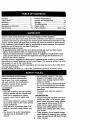
these accessorieswere availablewhen this lawn mowerwas produced.They are not
;hipped with your mower. They are alsoavailableat most Sears retailoutletsand service
-enters. Most Sears storescan also order repairpartsfor you, when you providethe model
_umber of your lawn mower. Some of these accessoriesmay not applyto your lawn mower.
LAWN MOWER PERFORMANCE
CUPPING DEFLECTOR
FOR REAR DISCHARGE LAWN MOWERS
GRASS CATCHERS
FOR
REAR DISCHARGE
LAWN MOWERS
MULCHERKFFS
STABILIZER
FOR
SIDEDISCHARGE
GRASS
LAWN CATCHERS
MOWERS
!
GAS CANS
LAWN
MOWER
MAINTENANCE
BELTS
SPARK PLUGS
AIR FILTERS
MUFFLERS
BLADES
BLADE ADAPTERS
WHEELS
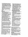
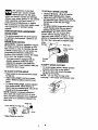
Read these instructions and this manual in its
TO REMOVE
entirety before you attempt to assemble or
operate your new lawn mower.
IMPORTANT: This lawn mower is shipped
WITHOUT OIL OR GASOUNE in the engine.
Your new lawn mower has been assembled
at the factory with the exception of those parts
left unassembled for shipping purposes. All
parts such as nuts, washers, belts, etc.,
necessary to complete the assembly have
been placed in the parts beg. To ensure safe
and proper operation of your lawn mower, all
parts and hardware you assemble must be
tightened securely. Use the correct tools as
necessary to ensure proper tightness.
CARTON
LAWN
ENGINE OIL
MOWER
FROM
• Remove loose parts included with mower.
• Cut down two end comers of carton and
lay end panel down flaL
• Remove all pacl_ng materials except
padding between upper and lower handle
and padding holding operator presence
control bar to upper handle,
• Roll lawn mower out of carton and check
carton thoroughly for additional loose
parts.
4
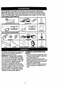
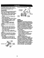
HOW TO SET UP YOUR LAWN MOWER
TO PREPARE
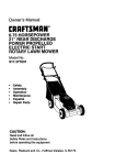
TO UNFOLD HANDLE
NOTE: Your battery must be charged
before you can start your lawn mower.
IMPORTANT: Unfoldhandles carefullyso as
not to pinchor damage controlcables.
• Raise handles un_ lower handle section
locks ir_oplace in mowing position.
• Remove protectivepadding, raise upper
handlesectioninto place on lower handle
and tightenboth handle knobs.
• Remove handle padding holdingoperator
presence controlbar to upper handle.
• Your lawn mower handlecan be adjusted
for your mowing comfort. Refer to "Adjust
Handle"in the Service and Adjustment
sectionof this manual.
BATTERY
• Disconnect engine battery connector
(male) from battery connector (female)
• Connect battery charger connector
(male) to battery connector (female).
• Plug battery charger into 110 volt A.C.
outlet.
• Leave battery charger connected for 24
hours before starting your engine for
the first time.
• After charging, connect engine connector (male) to battery connector (female).
Your engine has an integral alternator for
partial charging. Connect your battery
charger to charge battery as required.
IMPORTANT:
The engine alternator will
not charge a discharged battery.
Operator presence control
Upper handle
Lift up
At the end of the mowing season the
battery should be charged for 48 hours to
protect the battery during winter storage.
bar
-,,..
•-'_
Mowing
position
ACAUTION:
Always .disconnect the
engine connector (male) from the battery
connector (female) to prevent accidental
stading when transporting or storing your
lawn mower after the season.
_._-Lower handle
Engine
connector
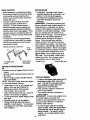
TO INSTALL ATTACHMENTS
Battery
charger
(Male)
Your lawn mower was shipped ready to be
usedas a mulcher.To convedto bagging or
discharging:
• Open rear door and remove mulcher plug.
Store mulcherplug in a safe place.
• You can now installcatcher or optional
clippingdeflector.
• To retum to mulchingoperation,install
mulcherplug into dischargeopening of
mower. Be sure alltabs are seated
properly.
Battery connector
(Female)
Mulcher plug
4gI,CAUTION:
Do not run your lawn
mower without mulcher plug in place or
approved clipping deflector or grass
catcher in place. Never attempt to
operate the lawn mower with the rear
door removed or propped open.
5
Batter
charger
connector
(Male)
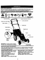
KNOW YOUR LAWN MOWER
_EAD THIS OWNER'S MANUAL.AND SAFETY RULES BEFORE OPERATING YOUR LAWN
_IOWER. Compare the illustrations with your lawn mower to familiarize yourself with the
;(_,atign9f v_ldqtt_ tT,(pn_L
__
adiustments. Save this manual for future reference.
fl_eeesymbds nmy appeer on your lawn mower or in Uterature suppged wilh Ihe product. Leem _
_
t_emeenk_
CAUTION
ENGINE
OR WARNING
ON
ENGINE
OFF
FAST
SLOW
CHOKE
FUEL
OIL
DANGER, KEEP HANDS
AND FEET AWAY
Operator presence control bar
Key Start Switch
Drive control lever
Engine zone control cable
Starter handle
Handle knob
Gasoline cap
Primer
Housing
Engine oil
cap w/
dipstick
IMPORTANT: This lawn mower is shipped
WITHOUT OIL OR GASOLINE in the engine.
Wheel adjuster
(on each wheel)
MEETS CPSC SAFETY REQUIREMENTS
Sears rotary walk-behind power lawn mowers conform to the safety standards of the American
National Standards Institute and the U.S. Consumer Product Safety Commission. The blade
tums when the engine is running.
Drive control lever - used to engage powerpropelled forward motion of lawn mower.
Mulcher plug * must be removed to convert to
bagging or discharging operation.
Key start switch- used to start the engine.
Operator presence control bar - must be
held down to the handle to startthe engine.
Release to stopthe engine.
Palmer - pumps additionalfuel from the
carburetorto the cylinderfor use when
starlinga cold engine.
Starter handle - used for startingthe engine.
6
TO ATrACH
mower
can result
in foreign
The
operation
of any
lawn
objects thrown into the eyes,
which can result in severe eye damage.
Always wear safety glasses or eye shields
while operating your lawn mower or
performing any adjustments or repairs.
We recommend a wide vision safety mask
over spectacles or standard safety
glasses.
HOW TO USEYOUR LAWN MOWER
ENGINE SPEED
The engine speed was set at the factory
for optimum performance. Speed is not
adjustable.
ENGINE ZONE CONTROL
_CAUTION:
Federal regulations require
an engine control to be installed on this
lawn mower in order to minimize the risk
of blade contact injury. Do not under any
circumstances attempt to defeat the
function of the operator control. The blade
turns when the engine is running.
• Your lawn mower is equippedwithan
operator presence controlbar which
requiresthe operatorto be positioned
behind the lawn mower handleto start and
operate the lawn mower.
TO ADJUST
CUI_NG
GRASS CATCHER
• Cloee the lift top lid. I_ifttop lid must ba
closed wh'de operating lawn mower.
• Lift the rear door on the mower housing
and place the grass catcher frame onto the
formed tabs on the rear door hinge
bracket.
• The grass catcher is secured to the lawn
mower housing when the rear door is
lowered onto the grass catcher frame.
A, CAUTION:
Do not run your lawn
mower without clipping deflector or
approved grass catcher in place. Never
attempt to operate the lawn mower with
the rear door removed or propped open.
Hinge
brack_
Rear door
Grass catcher
frame
Formed
tabs
TO EMPTY GRASSCATCHER
• To remove grass catcher, release operator
presence control bar to stop enojne.
• Lift up rear door end remove the grass
catcher by the handle.
NOTE:
Do not drag the bag when
emptying; it will cause unnecessary wear.
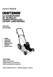
HEIGHT
• Raise wheels for low cut and lower wheels
for high cut.
• Adjust cutting height to suit your requirements. Medium position is best for most
lawns.
• To change cutting height, squeeze adjuster
lever toward wheel. Move wheel up or
down to suit your requirements. Be sure all
wheels are in the same setting.
NOTE: Adjuster is properly positioned
when plate tab inserts into hole in lever.
Also, 9-position adjusters (if so equipped)
allow lever to be positioned between the
plate tabs.
Plate Tab
Lower Wheels for High Cut,,._ / _
Raise Wheels for Low Cut
7
lJ
DRIVE CONTROL
ADD GASOUNE
• Self-propelling is controlled by holding
the operator presence control bar down
to the handle and pushing the drive
control lever forward until it clicks; then
release the lever.
• Fill fuel tank. Use fresh, clean, regular
unleaded gasoline with a minimum of 87
octane. Do not mix oil with gasoline.
Purchase fuel in quantities that can be
used within 30 days to assure fuel
freshness.
_WARNING:
Experience indicates that
alcohol blended fuels (calLed gasohol or
using ethanol or methanol) can attract
moisture which leads to separation and
formation of acids during storage. Acidic
gas can damage the fuel system of an
engine while in storage. To avoid engine
problems, the fuel system should be
emptied before storage of 30 days or
longer. Drain the gas tank, start the
engine and let it run until the fuel lines
and carburetor are empty. Use fresh fuel
next season. See Storage Instructions for
additional information.
Never usa engine
or carburetor cleaner products in the fuel
tank or permanent damage may occur.
ACAUTION:
Fill to bottom of gas tank
filler neck. Do not overfill. Wipe off any
spilled oil or fuel. Do not store, spill or
use gasoline near an open flame.
• Forward motion will stop when the
operator presence control bar is
released. To stop forward motion
without stopping engine, release the
operator presence control bar slightly
until the drive control disengages.
Hold
operator presence control bar down to
handle to continue mowing without selfpropelling.
• To keep drive control engaged when
tuming corners, push down on handle
and lift front wheels off ground while
turning lawn mower.
Operator presence control bar
To engage drive
control
Drive
control
Ddve control
disengaged
Engine oil cap
Gasoline filler cap
BEFORE STARTING ENGINE
OI.
Your lawn mower is shipped without oil in the
engine.
• Be sure mower is level and area around oil
fill is clean.
• Remove engine oil cap and fill to the full
line on the dipstick.
NOTE: Allow oil to settle down into engine
for accurate dipstick reading.
• Engine holds 20 ozs. of oil. For type and
grade of oil to use, see "ENGINE" in
Maintenance section of this manual.
• Pour oil slowly. Do not over fill.
• Check oil level before each use. Add oil if
needed. Fill to full line on dipstick.
• To read proper level, tighten engine oil cap
each time.
• Reinstall engine oil cap and tighten.
• Change the oil after every 25 hours of
operation or each season. You may need
to change the oil more often under dusty,
dirty conditions.
TO START ENGINE
• To start a cold engine, push primer five (5)
timea before Wing to start. Use a firm
push. This step is not usually necessary
when starting an engine which has
already run for a few minutes.
• Hold operator presence control bar
down to the handle.
• Tum electric start key clockwise to
crank engine.
IMPORTANT:
Do not crank engine more
not crank engine more than five
continous seconds between eack time
you try to start. Wait 5 to 10 seconds
between each attempt.
8
• To start engine using the auxiliary
starter handle, follow the steps above.
Exchange the use of the start key for
starter handle. Pull starter handle
quickly. Do not allow starter rope to
snap back.
• To stop engine, release operator
presence control bar.
NOTE: In cooler weather it may be
necessary to repeat priming steps. In
warmer weather over priming may cause
flooding and engine will not start. If you
do flood engine, wait a few minutes
before attempting to start and do not
repeat priming steps.
MOWING
TIPS
• Under certain conditions, such as very
tall grass, it may be necessary to raise
the height of cut to reduce pushing effort
and to keep from ovedoading the engine
and leaving clumps of grass clippings. It
may also be necessary to reduce
ground speed and/or run the lawn
mower over the area a second time.
• For extremely heavy cutting, reduce the
width of cut by ovedapping previously
cut path and mow slowly.
• For better grass bagging and most
cutting conditions, the engine speed
should be set in the fast position.
• When using a rear discharge lawn
mower in moist, heavy grass, clumps of
cut grass may not enter the grass
catcher. Reduce ground speed (pushing speed) and/or run the lawn mower
over the area a second time.
MULCHING MOWING TIPS
IMPORTANT: For best pedormance, keep
mower housing free of built-up grass
trash. See _Cleaning" in Maintenance section
of this manual.
. The special mulching blade will reout the
grass clippings many times and reduce
them in size so that as they fail onto the
lawn they will d_pers(_ into the grass and
not be not_=d. Also, the mulched grass wilt
biodegrvdequicklytoprovidenutrients for
the lawn. Always mulch with your highest
engine (blade) speed as this wiMprovide the
best recut'dng action of the blades.
• Avoid cutting your lawn when it is wet. Wet
grass tends to form dumps and interferes
with the mulching ac'_on. The best time to
mow your lawn is the early effemoon. At
this time the grass hes dried and the newly
cut area will not be exposed to the direct
sun.
• For best results, adjust the lawn mower
cuffing height so that the lawn mower cuts
off only the top one-third of the grass blades.
If the lawn is overgrown it will be necessary
to raise the height of cut to reduce pushing
effort and to keep from overloading the
engine and leaving dumps of mulched
grass. For extremely heavy mulching,
reduce your width of cut by overlapping
previously cut path and mow slowly.
• If a trail of clippings is left on the right
side of a rear discharge mower, mow in
a clockwise direction with a small
ovedap to collect the clippings on the
next pass.
• Pores in cloth grass catchers can
become filled with dirt and dust with use
• Certaintypesofgressandgrass_
may require that an area be mulched a
second time to completely hide the
clippings. When dofng a second cut, mow
ecross or perpendicular to the first cut peth`
• Change your cutting pattem from week to
week. Mow north to south one wsek then
and catchers will collect less grass. To
prevent this, regularly hose catcher off
with water and let dry before using.
• Keep top of engine around starter clear
and clean of grass clippings and chaff.
This will help engine air flow and extend
engine life.
change to eest to west the next week. This
will help prevent matting and graining of the
lawn.
g
.
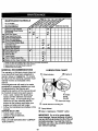
MAINTENANCE
SCHEDULE
FILL IN DATES
AS YOU COMPLETE
REGULAR SERVICE
Check for Loose Fasteners
Clean/Inspect Grass Catcher
ff Equipped)
Clean
Lawn Mower
(i !Clean
;lean Under
Lawn IDrive Cover
Power-Propellad Mowers)
drive belt/pulleys
;T Check
Power-Propl
(Power-PropalledMowers)
Check/Sharpen/Replace Blade
R Check/Sharpen/Replace
LubricationChart
LubricationChart
SERVICE DATES
_
ll/
I_
i_
I_
I/
Clean Battary/Rechar_le
IElactric Start MowersI
Check En_ina Oil Level
E Check Engine Oil L,
Change Engine Oil
_s
_e'
I_
b#'4
ll/1._
Clean
AirMuffler
Filter
Inspect
Clean or Replace Spark Plug
Replace Air Filter Paper Cartridge
12 3 4 -
Change more often when operating under a heavy load or In high ambient temperatures.
Sen,ice more often when operating in d_rtyor dusty cor_tions.
Replace blades more often when mowing in sandy soil.
Charge 48 hours at end of season.
GENERAL RECOMMENDATIONS
LUBRICATION
The warranty on this lawn mower does not
cover items that have been subjected to
operator abuse or negligence. To receive
full value from the warranty, operator must
maintain mower as instructed in this
manual.
CHART
(_ Wheel adjuster
ine oil
Some adjustments will need to be made
periodically to properly maintain your unit.
All adjustments in the Service and
Adjustments section of this manual should
be checked at least once each season.
\ Brake
• Once a year, replace the spark plug,
replace air filter element and check
blade for wear. A new spark plug and
clean/new air filter element assures
proper air-fuel mixture and helps your
engine run better and last longer.
• Follow the maintenance schedule in this
manual.
BEFORE EACH USE
• Check engine oil level.
• Check for loose fasteners.
LUBRICATION
Keep unit well lubricated (See "LUBRICATION CHART").
spring
bracket
Rear door hinge
(_) Handle bracket mounting pin
(_) Spray lubricant
• ) Refer to Maintenance "ENGINE" _.
IMPORTANT: Do not oil or grease plastic
wheel bearings. V'_cous lubricants will attract
dust and dirt that will shorten the life of the serf
lubricating bearings, If you feel they must be
lubricated, use only a dnJ, powdered graphite
typeiubrtcent
spanngly.
10
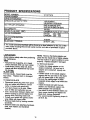
PRODUCT
SPECIFICATIONS
MODELNUMBER
917.377575
SERIALNUMBER
DATE OFPURCHASE
3ASOLINECAPACITWTYPE:
1.25 QUARTS
UNLEADED REGULAR
31LTYPE (API-SF/SG/SH):
SAE 30 (ABOVE 32°F)
SAE 5W-30 IBELOW 32°F)
20 OZS,
CHAMPION RJ19LM OR J19LM
INTAKE:
.004 - .008
EXHAUST: .004 - .008
OIL CAPACITY:
SPARK PLUG (GAP: .030")
VALVE CLEARANCE:
SOLID STATE IGNITION
AiR GAP:
.0125 IN.
BLADE BOLT TORQUE:
35-40 FT. LBS.
• The model and serial numbers willbe found on a decal attached
lawn mower housing.Record
provided above.
LAWN MOWlER
Always observe safety rules when performing
any rnaJntenence.
TIRES
• Keep tires free of gasoline, oil, or insect
control chemicals which can harm rubber.
• Avoid stumps, stones, deep ruts, sharp
objects and other hazards that may cause
tire damage.
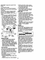
BLADE CARE
For best results, mower blade must be
kept sharp.
Replace bent or damaged
blades.
TO REMOVE
to the rear of the
both serial number and date of purchase in space
BLADE
• Disconnect spark plug wire from spark
plug and place wire where it cannot
come in contact with spark plug.
• Turn lawn mower on its side. Make
sure air filter and carburetor are up.
• Use a wood block between blade and
mower housing to prevent blade from
turning when removing blade bolt.
• Protect your hands with gloves and/or
wrap blade with heavy cloth.
• Remove blade bolt by turning counterclockwise.
NOTE: Remove the blade adapter and
check the key inside hub of blade adapter.
The key must be in good condition to work
properly. Replace adapter if damaged.
TO REPLACE
BLADE
• Position the blade adapter on the
engine crankshaft.
Be sure key in
adapter and crankshaft keyway are
aligned.
• Position blade on the blade adapter
aligning the two (2) holes in the blade
with the raised lugs on the adapter.
• Be sure the trailing edge of blade
(opposite sharp edge) is up toward the
engine.
• Install the blade bolt with the lock
washer and hardened washer into
blade adapter and crankshaft.
• Use block of wood between blade and
lawn mower housing and tighten the
blade bolt, turning clockwise.
• The recommended tightening torque is
35-40 ft. Ibs.
• Remove blade and attaching hardware
(bolt, lock washer and hardened
washer).
11
IMPORTANT:
treated.
Blade bolt is grade 8 heat
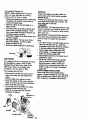
TO SHARPEN
BLADE
NOTE: We do not recommend
sharpening blade - but if you do, be sure the blade
is balanced.
Care should be taken to keep the blade
balanced. An unbalanced blade will
cause eventual damage to lawn mower or
engine.
• The blade can be sharpened with a file
or on a grinding wheel. Do not attempt
to sharpen white on the mower.
• To check blade balance, drive a nail
into a beam or wall. Leave about one
inch of the straight nail exposed.
Place
center hole of blade over the head of
the nail. If blade is balanced, it should
remain in a horizontal position. If either
end of the blade moves downward,
sharpen the heavy end until the blade
is balanced.
Crank shaft
Blade
keyway
• Remove any trash or grass cuttings
from inside the dust cover, pinion and/
or drive wheel gear teeth.
• Put wheels back in place.
• If after cleaning, the drive wheels do
not turn freely, contact your nearest
authodzed service center.
GEAR CASE
• To keep your drive system working
properly, the gear case and area
around the ddve should be kept clean
and free of trash build-up. Clean under
the drive cover twice a season.
• The gear case is filled with lubricant to
the proper level at the factory. The only
time the lubricant needs attention is if
service has been performed on the
gear case.
• If lubricant is required, use only Texaco
Starplex Premium 1 Grease, Part No.
750369. Do not substitute.
ENGINE
LUBRICATION
Use only high quality detergent oil rated
with API service classification SF, SG or
SH. Select the oil's SAE viscosity grade
according to your expected operating
temperature.
Key
Blade
SAE VISCOSITY GRADES
Blade
bolt
Lock
washer Hardened
washer
Crank
shaft
edge
Blade
adapter
GRASS CATCHER
• The grass catchermay be hosed with
water, butmust be dry when used.
• Check your grass catcheroften for
damage or deterioration. Through normal
use itwillwear. Ifcatcher needs replacing,
replaceonly with a manufacturerapproved
replacementcatcher. Give the lawn
mower model number when ordering.
DRIVE WHEELS
Check front drive wheels each time before
you mow to be sure they move freely.
The wheels not turning freely means
trash, grass cuttings, etc. are in the drive
wheel area and must be cleaned to free
drive wheels.
If necessary to clean the drive wheels,
check both front wheels.
• Remove hubcaps,
washers.
NOTE: Although multi-viscosity oils
(5W30, 10W30 etc.) improve starting in
cold weather, these multi-viscosity oils
will result in increased oil consumption
when used above 32°F. Check your
engine oil level more frequently to avoid
possible engine damage from running
low on oil.
Change the oil after every 25 hours of
operation or at least once a year if the
lawn mower is not used for 25 hours in
one year.
Check the crankcase
starting the engine and after each five (5)
hours of continuous use. Tighten oil plug
securely each time you check the oil
level.
hairpin cotters and
• Remove wheels from wheel adjusters.
oil level before
12
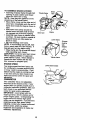
TO CHANGE ENGINE OIL
NOTE: Before tipping lawn mower to
drain oil, drain fuel tank by running
engine until fuel tank is empty.
• Disconnectspark plugwire from spark plug
and place wire where It cannot come in
cor_ with%oarkplug.
• Remove angineoilcsp;layasideon a
cleansurface.
• Tiphwn mower on itssideas shown and
drainoilintoa Bultabla
container.
Rock
lawnmower bed_and forth
toremove
traprw . of
ido
angle.
• Wipe off any spilledoil on lawn mower and
onsklaof englne.
• F_ engine withoil. Fdl only to the "FULL"
line on g_edipstk_ DO NOT ovedil.
• Replace engine oil cap.
• Reconnect spaxkplugwire to sped( plug.
MUFFLER
Inspect and replacecorrodedmuffleras it
couldcreate a fire hazard and/or damage.
SPARK PLUG
Change your spark plugeach yea[ to make
your enginestarteasier and runbetter. Set
sparkpluggapat .03Oinch.
CLEANING
IMPORTANT: For best performance, keep
mower housing free of built-up grass and
trash. Clean the underside of your mower
after each use.
_,CAUTION:
Disconnect spark plug wire
from spark plug and place wire where it
cannot come in contact with the spark
plug.
• Turn lawn moweron its side. Make sureair
filterand cad0uretorare up. Ctean the
undersideof your lawn mower by scraping
to remove build-upof grass and trash.
• Clean engine oftan to kesp trssh froro
accumu_fing.A clogged
angineruns
Container
AIR FILTER
Your engine will not run properly and may
be damaged by using a dirty air filter.
Replace the air filter every year, more
often if you mow in very dusty, dirty
conditions. Do not wash air filter.
TO CHANGE
AIR FILTER
• Remove the air filter by tuming clockwise to the stop and pull away from
collar.
• Remove filter from inside of cover.
• Clean the inside of the cover and the
collar to remove any dirt accumulation.
• Insert new filter into cover.
• Put air filter cover and filter into collar
hotterand shortensengine life.
• Keep finishedsurfscesand wheels free of
all gasoline,oil,etc.
• We do not recommendusinga garden
hose to dean lawn mower unlessthe
electricalsystem, muffler,airfilterand
carburetorare covered to keep water out.
Water in enginecan resultin shortened
enginelife.
CLEAN UNDER DRWE COVER
Clean under drive cover at least twicea
season. Scrape undersideof cover with putty
knifeor similartoolto remove any build-upof
trash or grass on undersideof drivecover.
aligning the tab with the slot.
• Push in on cover and turn counterclockwise to tighten.
Collar
Tmn
clockwise to
remove
Air filter
Air filter cover
counter
clockwise
to tighten 13
_CAUTION:
Before performing any
;ervice and adjustments"
, Release control bar and stop engine.
, Make sure the blade and all moving
TO ADJUST
parts have completely stopped.
, Disconnect spark plug wire from spark
plug and place where it cannot come in
contact with plug.
raising or lowering the handle,
• Remove upper handle and all parts
attached to lower handle.
• Remove hairpin cotters from lower
handle bracket mounting pin.
• Squeeze lower handle in to remove it
from mounting pins,
• Turn lower handle over to raise or lower
handle.
• Squeeze lower handle in and position
holes onto mounting pins on handle
bracket.
• Reassemble upper handle and all parts
removed from lower handle.
LAWN MOWER
TO ADJUST CUTTING
HEIGHT
See 'frO ADJUST CU'I-FING HEIGHT" in the
Operation section of this manual.
REAR DEFLECTOR
The rear deflector, attached between the rear
wheels of your lawn mower, is provided to
minimize the possibility that objects will be
thrown out the rear of the lawn mower into the
operator's mowing position, ff the rear
deflector becomes damaged, it should be
replaced.
TO REMOVE/REPLACE
HANDLE
The handle can be mounted in a high or
low position. The mounting holes in the
bottom of lower handle are off center for
Mowing
position
..
,_-_
DRIVE BELT
• Remove drive cover. Remove belt by
pushing down on gear case pulley and roll
belt off.
•Tum lawn mower on its side with carbure-
I
tor and fuel cap up.
• Remove blade.
• Remove debris shield.
• Remove belt from engine pulley on
crankshaft.
• Install new belt by reversing above steps.
• Always use factonJ approved belt to assure
fit and long life.
I
Low position
High position
v/
cover
_.____.J_
Lower
Belt
/handle
14
TO ASSEMBLE GRASS CATCHER
• Insert leg of tubular frame through front
opening of grass catcher and thread
frame into sewn hem of bag.
NOTE: Keep bag hem gathered on the
straight leg of the tubular frame.
• When frame comes out the other end of
sewn hem, immediately work the end of
frame down inside the bag as shown in
inset.
• Slide sewn hem evenly around the
tubular frame until both ends of frame
are exposed out of the front opening.
• Assemble lower frame to tubular frame
as shown. Be sure handle is outside of
bag and frames are fully seated as
shown in inset.
• Slip vinyl bindings over frame.
NOTE: If vinyl bindings are too stiff, hold
them in warm water for a few minutes. If
bag gets wet, let it dry before using.
• Close the flip lid. Flip lid must be closed
while operating lawn mower.
_CAUTION:
Do not run your lawn mower
without clipping deflector or approved
grass catcher in place. Never attempt to
operate the lawn mower with the rear
door removed or propped open.
ENGINE
Tubular frame
Sewn hem
Sewn
hem _
"_
FliI lid
Lower frame
(Frames
must be
fully
seated)
÷
Tubular frame
SPEED
Lower frame handle
Your engine speed has been factory set.
Do not attempt to increase engine speed
or it may result in personal injury. If you
believe that the engine is running too fast
or too slow, take your lawn mower to an
authorized service center for repair and
adjustment.
CARBURETOR
\
Your carburetor has a non-adjustable
fixed main jet for mixture control, if your
engine does not operate properly due to
suspected carburetor problems, take your
lawn mower to an authorized service
center for repair and/or adjustment.
IMPORTANT: never tamper with the
engine governor, which is factory set for
proper engine speed. Overspeeding the
engine above the factory high speed
setting can be dangerous, if you think the
engine-governed high speed needs
adjusting, contact your nearest authorzed
service center, which has proper
equipment and experience to make any
necessary adjustments.
15
bindings
Immediately prepare your lawn mower for
storage at the end of the season or if the unit
will not be used for 30 days or more.
Operator presence control bar
\
LAWNMOWER
manual):
• Lubricate as shown in the Maintenance
section of this manual.
• Be sure that all nuts, bolts, screws, and pins
are securely fastened. Inspect moving
partsfordamage,breakageandwear.
Replace if necessary.
• Touch up ell rusted or chipped paint
surfaces; sand lightly before painting.
HANDLE
You can fold your lawn mower handle for
storage.
• Squeeze the bottom ends of the lower
handle toward each other until the lower
handle dears the handle bracket, then
move handle forward.
• Loosen upper handle mounting bolts
enough to allow upper handle to be folded
back.
IMPORTANT: When folding the handle for
storage or transportation, be sure to fold the
handle as shown or you any damage the
control cables.
• When setting up your handle from the
storage position, the lower handle will
automatically lock into the mewing position.
Lower
handle
Handle
bmc_t
Squeeze tofold
/
,or
storage
When lawn mower is to be stored for a period
of time, dean if thoroughly, remove ell dirt,
grease, leaves, etc. Store in a dean, dry area.
• Clean entire lawn mower (See "CLEANING" in the Maintenance section of this
Lower _(_)_
handle
_
_
Upper
_
handle
,:A
Mowing
position
ENGINE
FUELSYSTEM
IMPORTANT: It is important to prevent gum
deposits from forming in essential fuel system
parts such as carburetor, f fuel filter, fuel hose
or tank dudng storage. Also, experience
indicates that alcohol blended fuels ( called
gesohof or using ethanol or methanol) can
attract moisture which leads to separation and
formation of acids during storage. Acidic gas
can damage the fuel system of an engine
while in storage.
• Drain the fuel tank.
• Start the engine and let it run until the fuel
lines and carburetor are empty.
• Never use engine or carburetor cleaner
products in the fuel tank or permanent
damage may occur.
• Use fresh fuel next season.
NOTE: Fuel stabilizer is an acceptable
alternative in minimizing the formation of fuel
gum deposits during storage. Add stabilizer
to gasoline in fuel tank or storage container.
Always follow the mix redo found on stabilizer
container. Run engine at least 10 minutes
after adding stabilizer to allow the stabilizer to
reach the carburetor. Do not drain the gas
tank and carburetor if using fuel stabilizer.
Hairpin
cotter
16
ENGINE OIL
Drain oil (with engine warm) and replace with
clean engineoil. (See "ENGINE" in the
Maintenance sectionof this manual),
CYUNDER
• Remove spark plug.
• Pour one ounce (29 ml) of oil through spark
plug hole intocylinder.
• Pullstarterhandleslowlya few times to
d_nbute oil.
• R aoo withnewsparkply.
OTHER
• Do notstore gasolinefrom one season to
another.
TROUBLESHOOTING
PROBLEM
Does not start
CHART
CAUSE
• Replace your gasoline can if your can
startsto rest. Rust and/ordirtin your
gasoline will cause problems.
• If possible,storeyour unit indoorsand
cover itto giveprot_
from dustand did.
• Cover your unitwith a suitable protective
cover that does not retainmoisture. Do
not use plastic. Plasticcannotbreathe
whichallows condensationto form and will
cause your unitto rust.
IMPORTANT: Never covermower while
engine and exhaustareas are stillwarm.
_kCAUTION: Never store the lawn
mower with gasoline in the tank inside a
building where fumes may reach an open
flame or spark. Allow the engine to cool
before storing in any enclosure.
CORRECTION
1. Dirty air filler.
2. Out of fuel.
3. Stale fuel.
1. Clean/replace air filter.
2. Fill fuel tank.
3. Drain tank and refill with
fresh clean fuel.
4. Drain fuel tank and
carburetor and refill tank
with fresh gasoline.
5. Connect wire to plug.
4. Water in fuel.
5: Spark plug wire is
disconnected.
6. Bad spark plug.
6. Replace spark plug.
7. Loose blade or broken blade 7. Tighten blade bolt or
adapter.
replace blade adapter.
8. Control bar in released
8. Depress control bar to
handle.
position.
9. Control bar defective.
9. Replace control bar.
Loss Of power
1. Rear of lawn mower housing 1. Set to =Higher Cut"
or cutting blade dragging
position.
in heavy grass.
2. Cutting too much grass.
2. Set to =Higher Cut"
position.
3. Dirty air filter.
3. Clean/replace air filter.
4. Clean underside of mower
4. Buildup of grass, leaves,
and trash under mower.
housing.
5. Check oil level.
5. Too much oil in engine.
6. Walking speed too fast.
!6. Cut at slower walking
speed.
Poor CUt - uneven
1. Wom, bent or loose blade.
2. Wheel heights uneven.
!3. Buildup of grass, leaves
and trash under mower.
17 ¸
t. Replace blade. Tighten
blade bolt.
2. Set all wheels at same
height
3. Clean underside
mower housing.
of
TROUBLESHOOTING
PROBLEM
Excesslve
vibration
CHART
CAUSE
CORRECTION
1. Worn, bent or loose blade.
2. Bent engine crankshaft.
Starter
to pull
rope hard
1. Engine flywheel brake is on 1. Depress control bar to
when control bar is released,
upper handle before
2. Bent engine crankshaft.
3. Blade adapter broken.
4. Blade dragging in grass.
Loss of drive
1. Replace blade. Tighten
blade bolt.
2. Contact an authorized
service center.
putting starter rope.
2. Contact an authorized
service center.
3. Replace blade adapter.
4. Move lawn mower to cut
grass or to hard surface.
1. Drive wheels not turning
control with drive control
engaged.
2. Belt not driving
1. Adjustor replace drive
cable.
Grass catcher
not filling {if so
equipped)
1. Cutting height too low.
2. Lift on blade worn off.
3. Catcher not venting air.
1. Raise cutting height.
2. Replace blade.
3. Clean grass catcher.
Hard to push
1. Grass is too high or wheel
height is too low.
2. Rear of lawn mower
housing or blade dragging
in grass.
3. Grass catcher too full.
4. Handle height position not
right for you.
1. Raise cutting height.
18
2. Put belt on pulleys or
replace belts if broken.
2. Raise rear of lawn mower
housing one (1) setting
higher.
3: Empty grass catcher.
4. Adjust handle height to
suit.
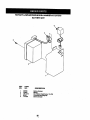
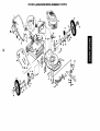
ROTARY LAWN MOWER MODEL NUMBER 917.377575
BATTERYART
4
3
KEY
NO.
1
2
3
4
5
PART
NO.
157553
750909
17411312
86353
111549X
DESCRIPTION
Battery Bracket
Battery
Hex Washer Head Screw 13x.750
Connector MountlngCllp
BatteryCharger
36
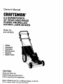
ROTARY LAWN MOWER - - MODEL NO. 917.377575
GEAR CASE ASSEMBLY PART NUMBER 702511
11
IS
17
14
KEY
NO.
PART
NO.
17490416
2
3
4
6
137055X004
137053
57072
48373
7
8
9
77881
137051
137074
KEY
NO.
DESCRIPTION
Tapping Screw
1/4-20 x 1-1/4
Engagement Bracket
Shifter
Seal
Gear Case Halves Kit
(Includes Key Nos. 4, and 7)
Buadng
Worm Shaft
Drive Shaft
10
11
12
13
14
15
16
17
18
19
PART
NO.
57079
131484
7(X)343
86447
137050
750436X
750369
12000003
850848
81585X004
NOTE:
All component dimensions given
in U.S. inches. 1 inch = 25.4 mm
7
DESCRIPTION
Hardened Washer
Clutch Yoke
Bushing
Plug
Helical Gear
Clutch Jaw
Grease
E-Ring
HI-Pro Key
Spring Bracket
ROTARY
LAWN MOWER MODEL NUMBER
917.377575
27
26
31
22
12
73
32
37
27
34
2S
30
29
28
7S
28
2_
7S
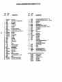
ROTARY LAWN MOWER MODEL NUMBER
KEY
NO.
1
2
3
6
7
9
10
11
12
13
14
15
16
17
20
21
22
23
25
26
27
28
29
30
31
32
34
35
37
38
39
40
PART
NO.
165452X479
158655
63601
136376
751152
151023
128415
150050
STD512505
144929
156374X479
700365X479
133190X479
140661X479
140540
150425
85543
87677
83923
57143
151138
142748
61651
750913X004
701037
700331X004
146630
700325X007
150078
88348
161814X479
161812X479
DESCRIPTION
UpperHandle
Zone ControlAsm. (IncludingCable)
NylonLockNut
HandleKnob
Locknut 1/4-20
Rear DoorKit
Pop Rivet
SelfTapping Screw #10-24
Hex Tapping Screw 1/4-20 x 1/2
Hex Washer Head Screw 1/4-20 x 2-1/8
Back Plate
Side Baffle
DischargeBaffle
Rear Baffle
Rear Skirt
MulcherPlug
EnginePulley
Hi-Pro Key #505
Nut
Washer
Wheel & Tire Assembly
ShoulderBolt3/8-16
Balleville Washer
Axle ArmAssembly
SelectorKnob
SelectorSpring
Spacer
Wheel AdjustingBracket
Thread Cutting Screw 5/16-18 x 3/4
Washer
Handle Bracket Assembly (Left)
Handle BracketAssembly (Right)
KEY
NO.
PART
NO.
41
44
46
47
48
49
50
51
52
53
55
56
57
58
59
61
62
64
150406
170029
851514
157101
851074
850263
851084
170031
85463
74760612
751592
88652
51793
157081X479
131959
132001
134612
......
72
73
74
75
76
77
- -
......
169806
66426
151440
161058
17600406
172627
917.377575
DESCRIPTION
Hex Head Thread Rolling Screw 3/8-16 x 1-1/8
Lawn Mower Housing (Incl. Key #14,15, 17, 51 & 52)
Blade Adapter
Blado22"
HardeeadWasher
Helical Washer 3/8-24 x 1-3/8 Grd. 8
Hex Head Machine Screw 3/8-24 x 1-3/8 Grd, 8
Front Baffle Kit
Danger Decal
Boll
Lock.nut3/8-16
HingeScrew
Hairpin Cotter
LowerHandle
Handle Bolt
RopeGuide
DobdsShield
Engine- (See Breakdown)Craftsman
Model 143.996504
See Battery Repair Parts Page
Zone ControlCable
Wire tie
HubCap
Warning Decal (Not Shown)
Screw Hex Serrated 114x 20.TT
Owner'sManual (EnglisldSpanish)
Available accessories not includedwith lawn mower:
7133623
Gas Can (2.5 gal,)
71 33500
FuelStabilizer
7133000
SAE 30W Oil (20 oz.)
7133417
Dust Shield
71 33316
MowerCover
71 33303
Chute Deflector
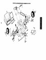
ROTARY LAWN MOWER MODEL NUMBER
917.377575
11
54
18
14
16
35
t
12
15
14
8
12
13
"j
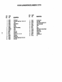
ROTARY LAWN MOWER MODEL NUMBER 917.377575
KEY
NO,
.b.
2
4
5
6
8
9
11
12
13
14
15
16
17
18
27
28
PART
NO.
145755
158755
146527
15O495
150182.
145212
150340
12000058
137054
88080
88118
67725
145793
701037
1436O3
15499O
DESCRIPTION
DriveControl
Hex Washer Head Screw 1/4-20 x 2-1/8
V-Belt
Spdng Retainer
Hubcap
Hex Nut
Wheel & Tire Assembly
E-Ring
Pinion
DustCover
FeltWasher
Washer 1/2 x 1-1/2 x .134
ControlBar
Selector Knob
Hex Washer Head Screw #10-24 x 3/4
DriveCover
KEY
NO.
PART
NO.
31
32
35
36
37
38
40
41
52
53
54
55
56
132010
137052
151521
702511
137O90
63601
75192
151520
144748
144747
166069
86012
751152
DESCRIPTION
Hex Flange Nut
Drive Pulley
Wheel AdjusterAssembly (Left)
Gear Caea Assembly
Spdng
Nut
Spdng
Wheal AdjusterAssembly (Right)
CstcherTube
CatcherThroat
Gmss_g
Ddvashaft Cover
Nut
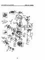
_M.41 m 1 3MAN
4-UY_;LI:
P..Nf31NI_
MODEL
NO. 143.996504
130
120
195
119
416
125
5
l _'310 110B_)__ 0A
_307
239
I'"
245
2
250
42
CRAFTSMAN
KEY
NO.
PART
NO.
1
2
6
7
37266
26727
33734
36557
12
12A
36775
36558
1213
14
15
16
17
18
36694
28277
30589
34839A
31335
651018
19
20
30
40
36281
32600
35801
40027
40028
41
40(_5
4-CYCLE
ENGINE
DESCRIPTION
Cylinder(Ind. 2,20 & 150)
DowelPin
BreatherElement
BreatherAss'y.
(Incl.6 & 12A)
BreatherTube
BreatherCover& Tube
(Incl. 12B)
Brea_erTube Elbow
Washer
GovernorRod(Incl. 14)
GovernorLever
GovernorLeverClamp
Screw,TorxT.15,
8-32 x 19/64"
ExtensionSpring
OilSeal
Crankshaft
Piston,Pin & Ring Set (Std.)
Piston,Pin & RingSet (.010"
os)
40026
42
43
45
40006
40007
2G381
36777
46
48
50
52
69
70
32610A
27241
36778
29914
35261
34311E
72
73
75
80
81
82
3C572
28833
27897
30574A
30590A
30591
83
86
89
90
92
93
100
101
1G3
3(To88A
650488
611004
611150
650815
6.50816
34443B
610118
651007
110
110A
110B
119
120
125
37047
36953
36954
36787
36825
37288
126
37289
130
135
150
151
151A
169
172
6021A
35395
31672
31673
40017
36783
36784
Piston& Pin Ass'y.(Std.)
(Incl.43)
Piston& PinAssay. (
.010" OS) (Ind.43)
Ring Set (Std.)
RingSet (.010" OS)
PistonPinRetainingRing
ConnectingRod Ass'y.
(Ind. 46)
ConnectingRod Bolt
Valve Ulter
Camshaft(MCR)
Oil PumpAss'y.
* Mounting FlangeGasket
Mounting Flange(
Ind. 72 thru 83,306)
Oil DrainPlug(Ind. 73)
DrainPlugGasket
Oil Seal
GovernorShaft
Washe_
GovernorGear Assay.
(Incl.81)
GovernorSpool
Screw, 114-20x 1-1/4"
RywhealKey
Flywheel
BellevilleWasher
RywheelNut
Solid State Ignition
SparkPlug Cover
Screw,Torx T-15,
10-24 x 15/16"
GroundWire
GroundWire
D.C. StarterWire
* CylinderHead Gasket
CyfinderHead
ExhaustValve (Std.)
(Include. 151)
Intake Valve (S_I.)
(Ind. 151)
Screw,5/16-18 x 1-1/2"
ReaistorSparkPlug(RJ19LM)
Valve Spdng
Valve Swing Cap
IntakeValve Seal
* Valve Cover Gasket
Valve Cover
MODEL NO. 143.996504
KEY
NO.
PART
NO.
174
178
182
184
30200
29752
6201
26756
186
186
189
191
36785
:32653
650831
36559A
196
196
207
216
223
224
238
239
241
245
250
260
261
262
263A
275
277
285
287
290
29_
298
300
301
305
306
3O7
3G9
310
313
314
315
322
322A
325
325A
347
370A
370C
380
390
386
400
610973
_
34336
33(366
650451
367B6
650932
34338
36919
36905
36920
36960
30_00
650831
369_1
36790
650988
35000A
650926
29774
26460
28763
36916
36246
35647
36996
35499
650562
35648
34080
650767
36852
35013
610885
35249
37152
651038
36261
37199
640174
590739
35709
36792B
416
36085
417
900
900
650821
-------
-- --
DESCRIPTION
"
*
*
"
Screw, 10-24 x 9/16"
Nut & LockWasher, 1/4-28
Screw, 1/4-28 x 7/8"
CarburetorToIntake Pipe
Gasket
Intake Pipe
GovernorUnk
Screw, 1/4-20 x 1/2"
S.E. Brake Bracket
(Include. 195)
Tern'real
Power ReatartSwitch
ThrottleUnk
R.P.M. AdjustingLever
Screw, 114-20x 1"
Intake Pipe Gasket
Screw, 10-32 x 49Fo4
Air CleanerGasket
AirCleanerCollar
AirCleaner Filter
AirCleanerCover
BlewerHousing
Screw, 10-24 x 9/16"
Screw, 114-20x 1/2"
StarterGrill
Muffler
Screw, 1/4-20 x2-5/16"
StarterCup
Screw,8-32 x 21/64"
Fuel Line
FuelUneClamp
Screw, 10-32 x 35/64"
FuelTank (Include. 292 & 301)
FuelCap
OilFillTube
'_Y'-Ring
'_O"-R_g
Screw, 10-32 x 1/2"
Dipstick
Spacer
Screw,8-32 _7/84"
AiternstorColt
Connector Body
Connector Body
SwingCUp
Swing Clip
Screw, 10-32x 51/64"
LubricaltonDecal
PnmerDecal
Carburetor(Incl.184)
RewindStarter
ElectricStarterMotor(12 Volt)
Gasket Set (Incl. Items
Marked *)
SparkArrestorKit (Incl.
417)(Opltonal)
Screw, 10-32 x 1/2"(Optional)
ReplecementEngineNONE
RedlecementS/B750832,
orderfrom71-999
RPM High2900 to3200
NOTE: This enginecould have been built wi_
590702 starter
NOTE: All componentdimensionsgivenin U.S.
inches 1 inch= 25.4 mm
43
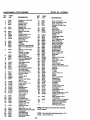
CRAFTSMAN
4-CYCLE
ENGINE
MODEL NO. 143.996504
KEY
NO.
PART
NO.
64o174
631615
2
4
5
6
7
16
17
_1_7
_11_
_11_
64O070
69or'J06
_1_7
631025
18
630763
640018
640053
631867
_1024
632019
_1028
_1021
_A
36
31
35
36
36A
37
40
44
47
<_;p,,-.-_17
631022
36045A
64OO8O
632766
632547
640175
27110A
630748
631027
--
48A
_1027
632790
KEY
NO.
PART
NO.
11
44
1
2
3
4
5
6
7
8
590702
590599A
59O6OO
59O6,96
59O6O1
59O697
59O696
59O699
5907O0
11
536703
12
590535
13
590701
DESCRIPTION
Carburetor (Incl. 184 of
Engine Parts List)
Throttle Shaft & Lever
Assembly
Throttle Retum Spring
* Dust SealWasher
* DustSeal (Throttle)
Throttle Shutter
• Shutter Screw
Fuel Fitting
Throttle CrackScrew/Idle
Speed Screw
TensionSpring
Idle Restdctor Screw
Idle Restdctor Screw Cap
Roat Bowl
• Roat Shaft
Float
• Float Bowl"O" Ring
• Inlet Needle, Seat, & Clip
(IncL 31)
SpdngClip
PdinerBull0/Ftetak_er
Ring
MainNozzle Tube
CarburetorTube
• "O" Ring, Main Nozzle Tube
High Speed Bowl Nut
Bowl NutWasher
• Welch Plug, Idle Mixture
WeR
* Welch Plug, Atmospheric
Vent
* Welch Plug
Repair kit (Incl. Items
Marked *)
DESCRIPTION
Recoil Starter
Spring Pin (Incl. 4)
Washer
Retainer
Washer
Brake Spring
Starter Dog
BogSpdng
Pulley& Rewind Spdng
Ass'y.
Staffer Housing Ass'y, (40
degreegrommet)
Starter Rope ( 98" X 9/64"
dia.)
StarterI-landle
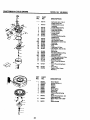
CRAFTSMAN 4-CYCLE ENGINE
MODEL NO. 143.996504
KEY
NO.
12
11C
----
PART
NO.
1
2
3
4A
513
6
7
8
10A
11C
35709
34955
34950
34954
34949A
349.53
3345O
34944
34945
590500
35714
12
13
14
15
16
17
18
34947
34946
34951
34952
34948
34953
5906O8
DESCRIPTION
Electric Starter (12 Volt)
Retainer Ring
SpdngRetainer
s_og
Gear
Drive End Cap Ass'y.
Lock Nut
Almature
Housing Ass'y.
ThrustWasher
Commutator End Cap Ass'y.
(Incl. brushes)
Bolt, 10-32 x 3-3/16'
PinionDriver
CuPWasher
Retainer Ring
Washer
Drive Nut
Washer
13
16
V--14
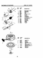
KEY
NO.
12
3
6
I$
PART
NO.
590739
590740
590616
590617
590618A
11
59O638
12
590535
13
14
590701
590760
--8
II
II1--'
DESCRIPTION
RewindStarter
Retainer
Starter Dog
Dog Spdng
Pulley & RewindSpring
Ass'y
Starter Housing Ass'y (40
degreegrommet)
Starter Rope (Length 98" x
9/64" dla.)
Starter Handle
SpdogClip
SERVICE NOTES
46
SERVICE NOTES
47
For in-home major brand repair service:
Call 24 hours a day, 7 days a week
1-800-4-MY-HOME
_" (1-800-469-4663)
Para pedir servicio de reparaci6n a domiciUo
1-800-676-5811
In Canada for all your service and parts needs call
Au Canada pour tout le service ou les pi_ces
1-800-665-4455
For the repair or replacement parts you need:
Call 6 am - 11 pm CST, 7 days a week
PartsDirect s"
1-800-366-PART
(1-800-366-7278)
Para ordenar piezas con entrega a domicilio
1-800-659-7084
For the location of a Sears Parts and Repair Center
in your area:
Call 24 hours a day, 7 days a week
1-800-488-1222
For information on purchasing a Sears Maintenance
Agreement or to inquire about an existing Agreement:
Call 9 am - 5 pm, Monday - Saturday
1-800-827-6655
SEAR8
Home Central"
172627
11.15.99
VB
Printed in U.S,A.