1
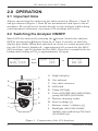
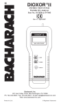
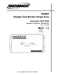
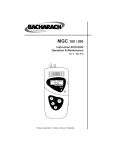
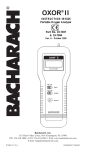
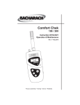
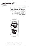
CO2 Analyzer 2810/2815/2820 Instruction 19-9222 Operation & Maintenance Rev. 9 – November 2005 2 3 Product Leadership • Training • Service • Reliability WARRANTY Bacharach, Inc. warrants to Buyer that at the time of delivery this Product will be free from defects in material and manufacture and will conform substantially to Bacharach Inc.’s applicable specifications. Bacharach’s liability and Buyer’s remedy under this warranty are limited to the repair or replacement, at Bacharach’s option, of this Product or parts thereof returned to Seller at the factory of manufacture and shown to Bacharach Inc.’s reasonable satisfaction to have been defective; provided that written notice of the defect shall have been given by Buyer to Bacharach Inc. within one (1) year after the date of delivery of this Product by Bacharach, Inc. Bacharach, Inc. warrants to Buyer that it will convey good title to this Product. Bacharach’s liability and Buyer’s remedy under this warranty of title are limited to the removal of any title defects or, at the election of Bacharach, to the replacement of this Product or parts thereof that are defective in title. THE FOREGOING WARRANTIES ARE EXCLUSIVE AND ARE GIVEN AND ACCEPTED IN LIEU OF (I) ANY AND ALL OTHER WARRANTIES, EXPRESS OR IMPLIED, INCLUDING WITHOUT LIMITATION THE IMPLIED WARRANTIES OF MERCHANTABILITY AND FITNESS FOR A PARTICULAR PURPOSE: AND (II) ANY OBLIGATION, LIABILITY, RIGHT, CLAIM OR REMEDY IN CONTRACT OR TORT, WHETHER OR NOT ARISING FROM BACHARACH’S NEGLIGENCE, ACTUAL OR IMPLIED. The remedies of the Buyer shall be limited to those provided herein to the exclusion of any and all other remedies including, without limitation incidental or consequential damages. No agreement varying or extending the foregoing warranties, remedies or this limitation will be binding upon Bacharach, Inc. unless in writing, signed by a duly authorized officer of Bacharach. Register Your Warranty by Visiting www.bacharach-inc.com Notice: Product improvements and enhancements are continuous, therefore the specifications and information contained in this document may change without notice. Bacharach, Inc. shall not be liable for errors contained herein or for incidental or consequential damages in connection with the furnishing, performance, or use of this material. No part of this document may be photocopied, reproduced, or translated to another language without the prior written consent of Bacharach, Inc. BACHARACH® is a registered trademark of Bacharach, Inc. All other trademarks are the property of their respective owners. Copyright © 1998–2005, Bacharach, Inc., all rights reserved. A Instruction 19-9222 CO2 Analyzer 2810/2815/2820 Contents 1.0 INTRODUCTION.................................................................................1 1.1 General........................................................................................1 1.2 Main Features.............................................................................1 1.3 Units of Measurement................................................................1 2.0 OPERATION........................................................................................2 2.1 Important Note...........................................................................2 2.2 Switching the Analyzer ON/OFF............................................... 2 2.3 Pump Operation (2815/2820)..................................................... 3 2.4 Pump Contamination (2815/2820)............................................. 3 2.5 High Humidity Gas Sampling (2820)........................................ 3 2.6 Storing Readings.........................................................................4 2.7 Battery Low Display...................................................................4 2.8 Battery Charge Display..............................................................5 2.9 Backlight.....................................................................................5 2.10 Audible Gas-Level Tone (2815/2820)........................................ 5 2.11 Fault Condition Warning..........................................................5 2.12 Powering Analyzer from Charger............................................. 6 2.13 Troubleshooting for Slow or Low Readings (2820)................... 6 2.14 Testing Incubators (2820)..........................................................7 3.0 MAINTENANCE..................................................................................8 3.1 Cleaning........................................................................................8 3.2 Sunlight........................................................................................8 3.3 Servicing.......................................................................................8 3.4 Software Version / Serial Number.............................................. 8 3.5 Factory Settings...........................................................................8 3.6 Battery Charging.........................................................................9 3.7 Calibration..................................................................................10 3.7.1 2810/2815 Calibration Procedure................................. 10 3.7.1.1 Air Calibration...............................................10 3.7.1.2 Gas Calibration..............................................12 3.7.2 2820 Calibration Procedure.......................................... 14 3.7.2.1 N2 Calibration................................................ 14 3.7.2.2 Gas Calibration..............................................15 4.0 PARTS & SERVICE..........................................................................18 4.1 Replacement Parts and Accessories.......................................... 18 4.2 Bacharach Service Centers........................................................19 Instruction 19-9222 CO2 Analyzer 2810/2815/2820 Notes: ii Instruction 19-9222 CO2 Analyzer 2810/2815/2820 1.0 INTRODUCTION 1.1 General Bacharach’s line of CO2 Analyzers are easy to use, but it is essential that these Operating Instructions be read and understood by all operators and maintenance personnel prior to using or servicing the instrument. The 2810/2815/2820 are compact and lightweight Carbon Dioxide analyzers that display the detected level of CO2 in the range of either 0–10,000 ppm (2810/2815) or 0–60% (2820). The analyzer is based on the infrared-absorption principle to detect the presence of CO2. The 2810 operates by diffusion only, while the 2815/2820 incorporates an internal pump for drawing in gas samples. Simply turn off the pump and the 2815/2820 samples by diffusion. A sampling tube and particulate filter are included with the 2815/2820 for remote sampling, while the 2820 also includes a desiccant filter to be used when sampling areas with high humidity. All analyzers can store gas readings in memory, which can later be downloaded to a personal computer via its integral IrDA communications link and the optional BACH-COM software. 1.2 Main Features •Sampling modes: sample draw (2815/2820) and/or diffusion (2810/2815/2820) •Automatic compensation for elevation and changes in barometric pressure •Variable-pitch tone indicates CO2 level (2815/2820) •Integral pump (2815/2820) •Battery capacity display •Manual (snapshot) and continuous data logging of readings with time and date stamp •Memory capacity for approximately 100 snapshot readings and 800 sets of continuous data logged readings •IrDA link for downloading stored data to a personal computer •Easy calibration in fresh air •Run-while-charging capability 1.3 Units of Measurement Depending the model ordered, the instruments’s LCD shows CO2 concentrations in either parts-per-million (2810/2815) or percent (2820). Please note that 1% = 10,000 ppm, and 0.01% = 100 ppm. Instruction 19-9222 CO2 Analyzer 2810/2815/2820 2.0 OPERATION 2.1 Important Note Always ensure that the analyzer’s gas inlet connector (Figure 1, Item C) and gas exhaust (Figure 1, Item B) are unobstructed and open to the atmosphere. Be careful not to breath directly on the analyzer while taking a measurement; otherwise, inaccurate CO2 readings will result. 2.2 Switching the Analyzer ON/OFF Switch ON the analyzer by pressing the button. Switch the analyzer OFF by pressing the button down for at least 3 seconds, or until the display goes blank. When first switched on, there is a warm-up period before the CO2 level is displayed – approximately 60 seconds for the 2810/ 2815 analyzer, and 20 seconds for the 2820. Note that a normal fresh-air background reading of CO2 is approximately 340 ppm. CO2 ANALYZER and then ppm CO2 340 C B 00.04 A -Digital display B -Gas exhaust D-IrDA link H J % CO2 C -Gas inlet connector A I or D E -Pump ON light E F -Power ON/OFF (2810/2815/2820); pump ON/OFF (2815/2820) F G-Battery charging socket G 2 3 H- Store readings (f1) I - Battery status / calibrate (f2) J -Backlight (2810/2815/2820); Audible tone indicating CO2 level (2815/2820) (f3) Figure 1. Components of the CO2 Analyzer Instruction 19-9222 CO2 Analyzer 2810/2815/2820 2.3 Pump Operation (2815/2820) With the analyzer already switched on, momentarily pressing the button switches on the pump. Pressing the button again turns the pump off. The supplied sampling probe and hose assembly can be connected to the gas inlet connector on the top of the analyzer for drawing in gas samples from hard-to-reach locations. Particulate filter P/N 54-0548 is placed on top of the gas inlet to prevent dust or dirt from being drawn into the instrument. Replace the particulate filter about once a month, or when the filter is contaminated as evidenced by a slower response time. Note that the combined sampling hose and probe length should not exceed 6 feet (1.8 m). Also note that the pump is intended for use only at normal atmospheric pressure, and is not designed to draw in gas samples against a vacuum or an obstruction such as a kink in the sampling hose. If an obstruction or negative-pressure gradient is present, then gas will not be drawn into the analyzer. Please consult the factory for applications where longer sampling lengths are required, or where it is necessary to draw against a vacuum. 2.4 Pump Contamination (2815/2820) Over time the pump can become contaminated, leading to a slower response time and lower readings. To check for pump contamination, turn on the pump and hold your index finger over the inlet fitting. The pump should normally stall. If the pump, however, continues to run, then the pump is contaminated and the analyzer needs to be returned to Bacharach for repair. 2.5 High Humidity Gas Sampling (2820) When using the 2820 to draw in gas samples from areas with high levels of humidity (e.g., incubators), first install the small round particulate filter that is supplied with the instrument onto the analyzer’s outlet using a 1.5" section of Portex tubing, and then connect a lure fitting to the particulate filter. Next, connect the Nafion tubing that is also supplied with the analyzer to the luer fitting using a 2" section of Portex tubing. On the other end of the Nafion tubing use a 6 to 12" section of Portex tubing to connect to the incubator. See Figure 2. Note: If the supplied Portex tubing is too small to fit onto the incubator’s gas sample port, then substitute a larger diameter tubing of your choice as long as the tubing is nonabsorbent. Instruction 19-9222 CO2 Analyzer 2810/2815/2820 For those situations where water droplets may be present in the sample line, you will need to install a water trap between the Nafion tubing and the incubator’s sample port as described in Section 2.14. After completing a test, continue to run the pump while sampling fresh air until the reading is below 0.1. This will purge out any residual CO2 and moisture before proceeding to the next test. 2.6 Storing Readings There are two reading-storage modes available: • Snapshot • Continuous Data Logging Pressing the f1 button once stores (takes a snapshot of) the reading shown on the display. ppm CO2 340 Clock icon is displayed once for a snapshot, and flashes during continuous logging. Pressing and holding down the f1 button for at least 2 seconds starts the continuous data logging of the readings at a preset interval (factory set at 30 seconds). The analyzer can store up to 100 snapshot readings and 800 sets of continuous-data-logged readings. Once the storage capacity has been exceeded, the latest readings will overwrite the oldest stored data. The stored data can be downloaded to a personal computer using the analyzer’s IrDA link and the optional BACH-COM software. This software can also be used to alter the data-logging interval, and produce tables and plots of time-based CO2 readings. 2.7 Battery Low Display When the battery voltage falls below a pre‑determined level, the display will alternate between its normal gas display and BattLow 340 In addition, the beeper will emit three rapid notes every 30 seconds. At this time the analyzer should be given a full charge per Section 3.6 as soon as possible. Instruction 19-9222 CO2 Analyzer 2810/2815/2820 2.8 Battery Charge Display The battery’s remaining charge is displayed by pressing the f2 button once. A bar graph in the lower part of this screen shows an approximation of the battery’s remaining charge. As the charge reduces, the bar graph decreases in size. Typical operating time from a full charge is 7 hours with the pump running, and 10 hours with the pump off. Battery Level = represents full charge = represents low charge 2.9 Backlight To view the LCD in poor ambient lighting conditions, turn on the display’s backlight by pressing the f3 button once (with the analyzer on). The backlight stays on for 5 seconds and then automatically turns off. 2.10 Audible Gas-Level Tone (2815/2820) An audible tone, which will increase in pitch with increasing CO2 levels, is activated by pressing and holding down the f3 button for 3 seconds. The tone is turned off by again pressing and holding down the f3 button for 3 seconds. 2.11 Fault Condition Warning The analyzer is capable of alerting the operator of an internal fault condition (i.e., a sensor failure or blockage in the infrared path). If a fault occurs, the analyzer’s beeper will sound continuously, and the following message is displayed until the analyzer is turned off. FAULT If the fault warning is displayed at any time, then the analyzer must be returned to Bacharach for servicing. Instruction 19-9222 CO2 Analyzer 2810/2815/2820 2.12 Powering Analyzer from Charger The analyzer can be continuously powered by its charger by connecting the charger as follows: 1. Switch ON the analyzer without the charger attached. Note: Connecting a charger to an analyzer that is switched OFF causes the analyzer to enter its charging mode, which in turn prevents the analyzer from being switched ON. 2. Plug the charger into the appropriate AC wall socket (or 12 VDC when using the optional cigarette lighter adapter). Then plug the charger’s output connector into the analyzer’s charging socket (Figure 1, Item G). The analyzer will now continuously run until it is switched OFF. 2.13 Troubleshooting for Slow or Low Readings (2820) It normally takes between 1 and 2 minutes to obtain a peak reading when testing an incubator. A slow or low reading can be caused by either a clogged desiccant filter or a contaminated CO2 sensor. Do the following to test for slow or low readings: 1. Remove both filters and sample again. 2. If this cures the problem, first replace the desiccant filter (P/N 07-1645) and sample again. Note that the particulate filter rarely becomes clogged, but if the problem returns with both fiters installed, replace the particulate filter (P/N 54-0548). 3. If the problem persists with the filters removed, reset the instrument to the factory settings per Section 3.5. If the reset is OK, then calibrate the instrument per Section 3.7.2. 4. If the factory reset fails, the CO2 sensor is contaminated and the instrument needs to be returned to Bacharach for repair and calibration. Instruction 19-9222 CO2 Analyzer 2810/2815/2820 2.14 Testing Incubators (2820) When testing incubators with the Model 2820, it is important to keep moisture from entering the instrument. Moisture can contaminate the IR cell and affect the readings. A Gas Dryer Tube (Nafion) is supplied with the instrument to remove excess water vapor (humidity) – refer to Section 2.5. The Nafion tube must be used at all times when testing in high humidity environments. When testing water-jacketed incubators, however, the potential exists of drawing water droplets that form inside the incubator’s internal sample line through the Nafion tubing and into the instrument. A water trap is provided with the instrument as an accessory to prevent water from being drawn into the instrument. The water trap is installed between the incubator and the Nafion tubing as shown in Figure 2. The need for the water trap can be determined by taking a few tests with it connected as described above. If water does not accumulate within the trap, then discontinue its use and just use the Nafion tubing. If the Nafion tubing becomes contaminated with water droplets, dry it out by flushing the tubing with a dry gas such as N2. Nafion tubing requires no other maintenance. INCUBATOR 6 to 12" PORTEX TUBING WATER TRAP (Note direction of arrow) Important! Remove particulate filter element from inside of water trap NAFION TUBING 2" PORTEX TUBING LUER FITTING Screws onto Particulate Filter 1.5" PORTEX TUBING PARTICULATE FILTER Figure 2. Installation of Nafion Tubing & Water Trap Instruction 19-9222 CO2 Analyzer 2810/2815/2820 3.0 MAINTENANCE 3.1 Cleaning Keep the analyzer clean by wiping it with a soft cloth dampened with a mild detergent solution. 3.2 Sunlight The unit should not be left out in direct sunlight, or in other areas where excessive heat exists, for long periods since component damage due to overheating may result. 3.3 Servicing There are no user‑serviceable parts inside the analyzer. Unauthorized disassembly of the unit will invalidate the warranty. 3.4 Software Version / Serial Number With the analyzer switched OFF, and while holding down the f1 button, switch ON the analyzer to display its software version and issue date. Releasing the f1 button displays the analyzer’s ID number for 5 seconds. Cd v1.24 20/5/98 → ID No. xxxxx 3.5 Factory Settings Important! The analyzer should only be returned to its factory settings when advised by a Bacharach Service Representative. With the analyzer switched OFF, and while holding down the f2 button, switch ON the analyzer. The display will show FACTORY SETTINGS Keep the f2 button depressed until the display shows RESET OK Instruction 19-9222 CO2 Analyzer 2810/2815/2820 Release the f2 button and follow the instructions from your local service representative. WARNING: After resetting the analyzer to its factory settings, it must be calibrated as described in Section 3.7 or erroneous gas reading may result. 3.6 Battery Charging When the ‘BattLow’ message is displayed (refer to Section 2.7), the analyzer must be recharged using the supplied battery charger. Important! The battery has a long shelf life, but it is recommended that the battery be recharged once a month if left unused. Batteries that have not been charged for several months should be given at least two charge/discharge cycles before using the analyzer. As with all rechargeable batteries, there are guidelines that should be observed: The battery should normally be charged at room temperature. Charging at temperatures below 54 °F (12 °C) should be avoided since this may cause a false indication of when the battery is charged, and could also damage the battery. Before beginning the charging process, first ensure that the analyzer is switched OFF. Next, plug the supplied charger into the appropriate AC wall socket (an optional 12 VDC charger with cigarette lighter adapter is also available). Then plug the charger’s output connector into the analyzer’s charging socket (Figure 1, Item G). The word “CHARGING” appears while the battery is being charged. Charging time is approximately 2 hours. Note: If the battery is deeply discharged, the display will remain blank for a few minutes before the battery begins charging. Once the battery is fully recharged, the analyzer will emit a beeping tone for 30 seconds and display the word “CHARGED”. At this time unplug the charger and remove its output connector from the analyzer. CHARGING >>>>>>>> Instruction 19-9222 → CHARGED CO2 Analyzer 2810/2815/2820 3.7 Calibration Calibration of a 2810/2815/2820 CO2 Analyzer consists of first performing either an Air Calibration on a 2810/2815 analyzer that zeros the instrument using fresh ambient air, or an N2 Calibration on a 2820 analyzer that zeros the instrument using 100% N2. Factory calibration provides the best accuracy over the analyzer’s entire detection range; however, the user can perform the optional Gas Calibration procedure that will improve the analyzer’s accuracy at a preprogrammed calibration point of 2,500 ppm CO2 for the 2810/2815, and 5% CO2 for the 2820. Note that the pre-programmed calibration point can be changed using BACH-COM software version 2.22 or higher. It is recommended that an Air Calibration or N2 Calibration be performed at the beginning of each work day or each time the instrument is switched OFF/ON. The analyzer should also be checked on a periodic basis with a higher concentration of CO2 to ensure that it still meets its accuracy specification. Follow the procedure under Section 3.7.1 to calibrate a 2810/2815 Low Range (LR) Analyzer, or the procedure under Section 3.7.2 to calibrate a 2820 High Range (HR) Analyzer. 3.7.1 2810/2815 Calibration Procedure 3.7.1.1 Air Calibration Perform this procedure in an uncontaminated enviroment such as outside fresh air, an empty room, or corridor where the air is assumed to contain 340 ppm CO2. Important! DO NOT perform an air calibration after sampling high concentrations of CO2 gas. Also, be careful that your breath does not affect this procedure. 1. Switch ON the analyzer, and then allow it to sample fresh air for 5 minutes. During this time, the internal pump of a 2815 Analyzer should be turned OFF. 10 → CO2 LR ppmCO2 Analyzer 340 Instruction 19-9222 CO2 Analyzer 2810/2815/2820 2. Press and hold down the f2 button until the ‘User Cal’ screen is displayed. Note that battery status is first displayed for approximately 2 seconds. User Cal Wait until the analyzer automatically switches to its ‘Air/Gas’ screen before proceeding. f1-> Air f3-> Gas 3. Press the f1 button to zero the analyzer using fresh ambient air. If the air calibration procedure was successful, the display will show AirCal OK If the procedure was unsuccessful, the message AirCal Failed will be displayed. If this happens, retry the Air Calibration procedure, ensuring that the analyzer is only exposed to fresh air. If the procedure is still unsuccessful, then the analyzer must be returned to a Bacharach Service Center for evaluation. 4. This completes the Air Calibration procedure. If desired the analyzer can now be spanned to a known concentration of CO2 gas per Section 3.7.1.2. Instruction 19-9222 11 CO2 Analyzer 2810/2815/2820 3.7.1.2 Gas Calibration WARNING: This procedure assumes that you are using the Bacharach Calibration Kit as listed in Section 4.1, Calibration Accessories. When using a non Bacharach gas regulator, however, you must also use an in-line flowmeter to ensure that the gas flow to the analyzer is between 100 and 200 cc/minute. Improper flow can cause erroneous gas readings! Important! Always perform an Air Calibration first. 1. Press and hold down the f2 button until the ‘User Cal’ screen is displayed. User Cal Wait until the analyzer automatically switches to its ‘Air/Gas’ screen before proceeding. f1-> Air f3-> Gas 2. Press the f3 button to display the Gas Calibration screen. f1> 2500 340 The top line shows the preset calibration gas value that must be applied to the analyzer’s inlet. The bottom line shows the current CO2 reading. Note: The analyzer is most accurate around the calibration gas value. If the analyzer, however, is routinely used to monitor CO2 levels that are much higher or lower than the preset value, then it is recommended that the analyzer be calibrated on a concentration of gas that is close to the gas level being monitored. This operation requires that the preset calibration gas value be reset higher or lower using the optional BACHCOM software, version 2.22 or higher. 12 Instruction 19-9222 CO2 Analyzer 2810/2815/2820 3. Using the Calibration Accessories listed in Section 4.1, attach a CO2 calibration gas cylinder to the inlet of the analyzer as shown in Figure 3. The applied CO2 concentration must equal the gas value displayed in the top line of the Gas Calibration screen. Important! Do not attempt to calibrate the analyzer if the pressure gauge closest to the tank reads below 5 psi. 4. Adjust the regulator attached to the gas cylinder for an outlet pressure of 2 psi (equivalent to a flow rate of approximately 120 cc/minute). Observe that the gas level displayed on the second line of the Gas Calibration screen should slowly rise to the value displayed in the top line. 5. Allow the calibration gas to flow until the second line of the Gas Calibration screen stabilizes, then press the f1 button. If the gas calibration procedure was successful, the display will show If the procedure was unsuccessful, the message GasCal OK GasCal Failed will be displayed. If this happens, retry the Gas Calibration procedure, ensuring that the analyzer is exposed to the correct concentration of calibration gas. If the procedure is still unsuccessful, then the analyzer must be returned to a Bacharach Service Center for evaluation. 6. This completes the Gas Calibration procedure. Shut off the regulator; then remove and store the calibration accessories. Instruction 19-9222 13 CO2 Analyzer 2810/2815/2820 3.7.2 2820 Calibration Procedure 3.7.2.1 N2 Calibration The following procedure uses 100% N2 to zero the analyzer. (Fresh ambient air that is assumed to contain 340 ppm CO2 can be used if N2 is not available.) Important! DO NOT perform an N2 calibration after sampling high concentrations of CO2 gas. Also, be careful that your breath does not affect this procedure. 1. Switch ON the analyzer. But before proceeding, allow the analyzer to sample fresh air for 5 minutes with its internal pump turned OFF. → CO2 HR Analyzer % CO2 00.00 2. Press and hold down the f2 button until the ‘User Cal’ screen is displayed. Note that battery status is first displayed for approximately 2 seconds. User Cal Wait until the analyzer automatically switches to its ‘N2/Gas’ screen before proceeding. f1-> N2 f3-> Gas 3. Using the calibration accessories listed in Section 4.1, attach a 100% N2 gas cylinder to the inlet of the analyzer as shown in Figure 3. Then adjust the regulator attached to the gas cylinder for an outlet pressure of 2 psi (equivalent to a flow rate of approximately 120 cc/minute). If N2 is unavailable, turn ON the analyzer’s pump and allow it to draw in fresh air for at least 30 seconds before proceeding. Important! When using N2 gas, do not attempt to calibrate the analyzer if the pressure gauge closest to the tank reads below 5 psi. 14 Instruction 19-9222 CO2 Analyzer 2810/2815/2820 4. Press the f1 button to zero the analyzer using 100% N2 or fresh air. If the N2 Zero procedure was successful, the display will show N2 Cal OK If the procedure was unsuccessful, the message N2 Cal Failed will be displayed. If this happens, retry the N2 Zero procedure, ensuring that the analyzer is only exposed to either 100% N2 or fresh air. If the procedure is still unsuccessful, then the analyzer must be returned to a Bacharach Service Center for evaluation. 5. This completes the N2 Calibration procedure. If desired the analyzer can now be spanned to a known concentration of CO2 gas per Section 3.7.2.2. 3.7.2.2 Gas Calibration WARNING: This procedure assumes that you are using the Bacharach Calibration Kit as listed in Section 4.1, Calibration Accessories. When using a non Bacharach gas regulator, however, you must also use an in-line flowmeter to ensure that the gas flow to the analyzer is between 100 and 200 cc/minute. Improper flow can cause erroneous gas readings! Important! Always zero the analyzer first using 100% N2 or fresh ambient air. 1. If the pump is running, turn it OFF. 2. Press and hold down the f2 button until the ‘User Cal’ screen is displayed. User Cal Instruction 19-9222 15 CO2 Analyzer 2810/2815/2820 Wait until the analyzer automatically switches to its ‘N2/Gas’ screen before proceeding. f1-> N2 f3-> Gas 3. Press the f3 button to display the Gas Calibration screen. f1->05.0 00.0 The top line shows the preset calibration gas value that must be applied to the analyzer’s inlet. The bottom line shows the current CO2 reading. Note: The analyzer is most accurate around the calibration gas value. If the analyzer, however, is routinely used to monitor CO2 levels that are much higher or lower than the preset value, then it is recommended that the analyzer be calibrated on a concentration of gas that is close to the gas level being monitored. This operation requires that the preset calibration gas value be reset higher or lower using the optional BACHCOM software, version 2.22 or higher. 4. Remove the 100% N2 cylinder (if used); then attach a CO2 calibration gas cylinder to the inlet of the analyzer as shown in Figure 3. The applied CO2 concentration must equal the gas value displayed in the top line of the Gas Calibration screen. Important: Do not attempt to calibrate the analyzer if the pressure gauge closest to the tank reads below 5 psi. 5. Adjust the regulator attached to the gas cylinder for an outlet pressure of 2 psi (equivalent to a flow rate of approximately 120 cc/minute). Observe that the gas level displayed on the second line of the Gas Calibration screen should slowly rise to the value displayed in the top line. 16 Instruction 19-9222 CO2 Analyzer 2810/2815/2820 6. Allow the calibration gas to flow until the second line of the Gas Calibration screen stabilizes, then press the f1 button. If the gas calibration procedure was successful, the display will show GasCal OK If the procedure was unsuccessful, the message GasCal Failed will be displayed. If this happens, retry the Gas Calibration procedure, ensuring that the analyzer is exposed to the correct concentration of calibration gas. If the procedure is still unsuccessful, then the analyzer must be returned to a Bacharach Service Center for evaluation. 7. This completes the Gas Calibration procedure. Turn off the regulator; then remove and store the calibration accessories. (/3% 0USHHOSEOVER THEANALYZERgSINLET CONNECTOR &ORTHE!NALYZERBE SURETHATTHEPUMPISNOTRUNNING 0UMPLIGHTMUSTBE/&& 2%'5,!4/2 2EGULATORAND(OSEAREPART OF#ALIBRATION+IT3EE 3ECTION #ALIBRATION!CCESSORIES #/OR. #ALIBRATION#YLINDER !DJUSTREGULATORKNOBFORANOUTLET PRESSUREOFPSICORRESPONDINGTOA FLOWRATEOFBETWEENANDCCMIN Figure 3. Calibration Equipment Instruction 19-9222 17 CO2 Analyzer 2810/2815/2820 4.0 PARTS & SERVICE 4.1 Replacement Parts and Accessories Complete Kits CO2 Analyzer 2810 – measures 0 to 10,000ppm CO2, includes particulate filter & wall charger......................................................19-8023 CO2 Analyzer 2815 – meausres 0 to 10,000 ppm CO2, includes internal pump, particulate filter, wall charger, & gas sample tube....................................................................................................19-8028 CO2 Analyzer 2820 – measures 0 to 60% CO2, includes internal pump, wall charger, particulate filter, water trap, Nafion & Portex tubing.....................................................................................19-8025 Replacement Parts 110/240 VAC USA & European Wall Charger (all)...........................19-3312 Luer Fitting, Male (2815/2820)........................................................103-2563 Gas Sample Tube, 6 inches (2815).....................................................11-0118 Particulate Filter (2815/2820)............................................................54-0548 Nafion & Portex Tubing Kit (2820)....................................................19-3318 Water Trap (2820)...............................................................................19-3265 Accessories 12 VDC Charger w/ Cigarette Lighter Adapter................................19-3302 Carrying Case, Small (10 5/8"L x 8 1/2"W x 3 3/16"H)..........................19-3337 Carrying Case, Large (13 1/2"L x 10 13/16"W x 4"H)...........................19-3311 IrDA Interface Kit & BACH-COM Software.....................................19-3301 Protective Boot....................................................................................19-3304 Table Top Stand..................................................................................19-3307 Calibration Accessories Calibration Kit(w/ regulator and tubing)..........................................19-8027 Air Cal Check Gas, 340 ppm CO2, 17 liter tank (2810/2815)...........24-1125 Calibration Gas, 2,500 ppm CO2, 17 liter tank (2810/2815).............24-1130 Calibration Gas, 100% N2, 17 liter tank (2820).................................23-4003 Calibration Gas, 5.0% CO2, 17 liter tank (2820)...............................24-1126 18 Instruction 19-9222 CO2 Analyzer 2810/2815/2820 4.2 Bacharach Service Centers United States Bacharach Inc. 621 Hunt Valley Circle New Kensington, PA 15068 Phone: 724-334-5051 Fax: 724-334-5723 Email: [email protected] Canada Bacharach of Canada, Inc. 250 Shields Court Unit #3 Markham, Ontario L3R 9W7 Canada Phone: 905-470-8985 Fax: 905-470-8963 Email: [email protected] México Bacharach de México Playa Regatas No. 473 Tercer Piso Col. Militar Marte Delegación Iztacalco, 08830 México D.F. México Phones:+52-555-634-7740 +52-555-634-7741 Fax: +52-555-634-7738 Email: [email protected] Website: www.bacharach-mexico.com Europe Bacharach Instruments Sovereign House, Queensway Royal Leamington Spa Warwickshire CV31 3JR United Kingdom Phone: +44-1926-338111 Fax: +44-1926-338110 Email: [email protected] Instruction 19-9222 19 CO2 Analyzer 2810/2815/2820 Notes: 20 Instruction 19-9222 CO2 Analyzer 2810/2815/2820 Notes: Instruction 19-9222 21 CO2 Analyzer 2810/2815/2820 Notes: 22 Instruction 19-9222 CO2 Analyzer 2810/2815/2820 Notes: Instruction 19-9222 23 Headquarters: 621 Hunt Valley Circle, New Kensington, PA 15068 Ph: 724-334-5000 • Fax: 724-334-5001 • Toll Free: 800-736-4666 Website: www.bacharach-inc.com • E-mail: [email protected] Printed in U.S.A.