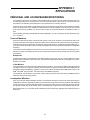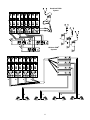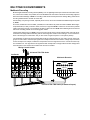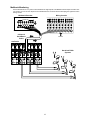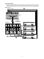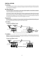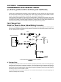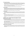
1
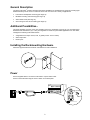
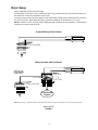
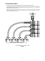
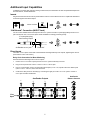
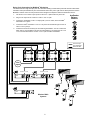
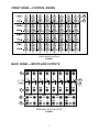
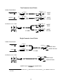
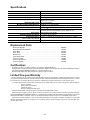
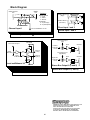
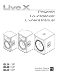
AuxPander Auxiliary Expander User Guide ! IMPORTANT SAFETY INSTRUCTIONS ! 1. 2. 3. 4. 5. 6. 7. 8. 9. READ these instructions. KEEP these instructions. HEED all warnings. FOLLOW all instructions. DO NOT use this apparatus near water. CLEAN ONLY with dry cloth. DO NOT block any ventilation openings. Install in accordance with the manufacturer’s instructions. Do not install near any heat sources such as radiators, heat registers, stoves, or other apparatus (including amplifiers) that produce heat. DO NOT defeat the safety purpose of the polarized or groundingtype plug. A polarized plug has two blades with one wider than the other. A grounding type plug has two blades and a third grounding prong. The wider blade or the third prong are provided for your safety. If the provided plug does not fit into your outlet, consult an electrician for replacement of the obsolete outlet. 10. PROTECT the power cord from being walked on or pinched, particularly at plugs, convenience receptacles, and the point where they exit from the apparatus. 11. ONLY USE attachments/accessories specified by the manufacturer. 12. USE only with a cart, stand, tripod, bracket, or table specified by the manufacturer, or sold with the apparatus. When a cart is used, use caution when moving the cart/apparatus combination to avoid injury from tip-over. 13. UNPLUG this apparatus during lightning storms or when unused for long periods of time. 14. REFER all servicing to qualified service personnel. Servicing is required when the apparatus has been damaged in any way, such as power-supply cord or plug is damaged, liquid has been spilled or objects have fallen into the apparatus, the apparatus has been exposed to rain or moisture, does not operate normally, or has been dropped. This symbol indicates that there are important operating and maintenance instructions in the literature accompanying this unit. This symbol indicates that dangerous voltage constituting a risk of electric shock is present within this unit. WARNING: Voltages in this equipment are hazardous to life. No user-serviceable parts inside. Refer all servicing to qualified service personnel. The safety certifications do not apply when the operating voltage is changed from the factory setting. 2001, Shure Incorporated 27A8778 (BF) Printed in Italy General Description The Shure AuxPander auxiliary expander extends the capabilities of a standard mixing console by providing eight additional auxiliary sends. Use it to create both stereo and mono mixes for a variety of applications: S S S S Personal and loudspeaker monitoring (see Page 10) Multitrack recording and monitoring (see Page 12) Stereo effect sends (see Page 14) Zone mixing and mix-minus matrixing (see Page 15) Additional Possibilities... This guide illustrates just a few of the many possible uses for the AuxPander. However, let your own applications determine what works best for you, or use your imagination to create new, personalized applications. For more ideas, investigate the following AuxPander features: S S S Assignable insert output: remote, local, or global (INSERT ASSIGN switch) Stereo output bus Direct inputs Installing the Rackmounting Hardware Attach the supplied rackmount brackets and hardware for rack installations. Power Use the supplied cable to connect the AuxPander to a power mains outlet. Power on the AuxPander using the POWER switch on the back panel. 2 Basic Setup Figure 1 illustrates the basic AuxPander setup. The AuxPander connects to the mixing console insert points. Any processors that were connected to the mixing console inserts are moved to the AuxPander INSERT jacks. The mixing console receives the same signal as in the original setup, including the processed signal from the mono and stereo processors. Eight additional auxiliary outputs are available at the AuxPander OUTPUT jacks. NOTE: For details on how to use insert points, including what type of cables to use, see Appendix II, Fundamentals of Insert Points on Page 16 of this manual. Original Mixing Console Setup Mono Processor Stereo Processor Channel Insert Points Channel Inputs Mixing Console with AuxPander Mono Processor 8 Channel 1/4” Phone TRS-TRS Snake Cable* Stereo Processor INSERT Jacks IN/OUT Jacks OUTPUT Jacks Channel Insert Points Channel Inputs 8 AuxPander Outputs * NOTE: Eight-channel 1/4” TRS–TRS snakes are easily obtained and make connecting the AuxPander to a mixer especially neat and easy. BASIC SETUP FIGURE 1 3 Creating Stereo Mixes Create stereo mixes using the level and balance controls on the front panel of the AuxPander. On the front panel, each column corresponds to the input at one of the IN/OUT jacks, and each row corresponds to a stereo output pair. Use the LEVEL knobs to add signal to each stereo output pair. Use the BALANCE controls to move signal between the left and right outputs. Figure 2 shows signal from the AuxPander Channel 1 input (IN/OUT 1) routed to each stereo output. To add signal from the Channel 2 input (IN/OUT 2) to the STEREO A outputs, use the LEVEL control in the same row (STEREO A / OUTS 1–2) in the second column (2) . Channel 1 1 Stereo Outputs or Mono Outs 1–8 FLOW DIAGRAM FOR CHANNEL 1 INPUT FIGURE 2 4 2 3 Additional Input Capabilities In addition to receiving audio input from mixing console inserts, the AuxPander can also accept standard inputs from line-level devices, as described below. Inserts Plug line-level sources into the INSERT jack and set the INSERT ASSIGN switch to REMOTE. Adjust level and balance to feed the signal to the stereo outputs. INSERT ASSIGN “Half-Normal” Connection (IN/OUT Jack) You can connect unbalanced line-level outputs to the IN/OUT jacks. Insert the 1/4” phone plug halfway into the IN/OUT jack until the first “click.” The INSERT jacks remain available for inserting processing locally. 1/ ” 4 mono phone plug from line-level output AuxPander IN/OUT jack First “click” Direct Inputs The DIRECT INPUT jacks on the back of the AuxPander feed signal directly to the outputs, bypassing the mix bus. (See Callout H in the next section.) Daisy Chain Connection for Mono Monitoring Use this method to add a signal to four mono outputs. 1. Use the BALANCE knobs to pan input from the IN/OUT jacks all the way to the left. 2. Plug a mono input into the STEREO A DIRECT INPUT L/MONO jack. 3. Use a 1/4” phone patch cord to connect all the right outputs (OUTPUT–R) outputs to the mono direct inputs (DIRECT INPUT–L/MONO) of the next stereo bus. 4. Continue the daisy chain as necessary by connecting the right (R) STEREO D OUTPUT jack to a DIRECT INPUT jack of another AuxPander. AuxPander Balance Controls AuxPander Outputs 1 2 3 Line Input 5 4 Daisy Chain Connection for MixMode Monitoring This method sends a single line input (such as a click track or mixing console submix) to the left channel of each PSM transmitter and a personalized mix (from the AuxPander stereo bus) to the right channel. Each performer uses the MixMode balance control on their personal monitor bodypack to adjust the relative level between the two. 1. Use the BALANCE knobs to pan input from the IN/OUT jacks all the way to the left. 2. Plug a mono input into the STEREO A DIRECT INPUT R jack. 3. Connect the AuxPander STEREO A output jacks (L/MONO and R) to the first PSM transmitter INPUT jacks. 4. Connect the PSM transmitter LOOP OUT 2/R jack to the AuxPander right STEREO B DIRECT INPUT jack (R). 5. Continue the chain as necessary for the remaining transmitters. You can continue the daisy chain to accommodate more than four transmitters by connecting the 2/R LOOP OUT of a fourth transmitter to a DIRECT INPUT jack of another AuxPander. AuxPander Balance Controls from Line Input from AuxPander Stereo Mix Bus Line Input LOOP OUT 2/R A LOOP OUT 2/R L AuxPander Mix Line Input B L R AuxPander Mix Line Input L A C Wireless PSM Systems B C 6 R AuxPander Mix Line Input R FRONT PANEL—CONTROL KNOBS B A FRONT PANEL CONTROLS FIGURE 3 BACK PANEL—INPUTS AND OUTPUTS E F D C G H REAR PANEL INPUT AND OUTPUT FIGURE 4 7 A Level Control Knobs Each LEVEL knob increases or decreases the input signal level at one of the four stereo output buses. The detented stop at the midway position of each level control knob indicates unity gain (the signal level at the stereo bus equals the input level at the AuxPander IN/OUT jack). Turn the knob clockwise beyond the detented position to increase the level up to 12 dB. B Balance Control Knobs Each BALANCE knob pans the signal between the left and right outputs of a stereo bus. Set the knob to the middle, detent position to make the signal level equal at both outputs. C IN/OUT Jack NOTE: This section assumes a basic understanding of insert points. To learn about the fundamentals of insert points, see Appendix II. Normal Connection (from Insert Point): Use a 1/4” TRS–TRS cable to connect any of these jacks to another mixer’s unbalanced channel insert. The AuxPander splits the signal into two, routing one to its mix bus and the other back to the mixer’s insert point. The signal returning to the mixer is unaffected, unless you choose to first route it through the AuxPander’s inserts. IMPORTANT: Depending on whether your mixer inserts are tip-send or ring-send, you may need to change the TIP ASSIGN switch position. See Callout D—Tip Assign Switch. D Tip Assign Switch This switch makes the AuxPander compatible with all mixing consoles. It reverses the function of the tip and ring contacts of the IN/OUT jack. NOTE: Change the position of this switch if, after connecting the AuxPander to the mixing console inserts, the signal does not return to the console. E TIP ASSIGN IN OUT IN: Use this setting with tip-send inserts. The AuxPander receives input signal from the plug tip and sends output back through the plug ring. (Tip is in.) TIP ASSIGN IN OUT OUT: Use this setting with ring-send inserts. The AuxPander receives input signal from the plug ring and sends output back through the plug tip. (Tip is out.) Insert Jack Use an insert cable (”Y” cable) to connect these insert jacks to serial processors (compressors, gates, equalizers). You can route the returned (processed) insert signal three different ways. See callout F— Insert Assign Switch. NOTE: The INSERT tip/ring assignment matches the IN/OUT tip/ring assignment, as determined by the TIP ASSIGN switch setting. 8 F Insert Assign Switch The INSERT ASSIGN switches route processed signal returning from signal processors or other devices connected to the AuxPander INSERT jacks. G INSERT ASSIGN REMOTE: Processed signal goes to the mixing console only (signal going to the AuxPander mix bus remains unprocessed). INSERT ASSIGN LOCAL: Processed signal goes to the AuxPander only (signal returned to mixing console is unprocessed). INSERT ASSIGN GLOBAL: Inserted processor affects signal at both the AuxPander and the mixing console. Output Jacks There are four pairs of impedance-balanced, line-level, 1/4” OUTPUT jacks. Create mixes for these outputs using the front panel LEVEL and BALANCE knobs. H Direct Input Jacks Connect balanced or unbalanced, line-level audio to the DIRECT INPUT jacks. Signals at the DIRECT INPUT jacks operate at unity gain. They sum with the signal at the left (L/MONO) and right (R) OUTPUT jacks after the mix bus. Mono Operation: If you plug a connector into the L/MONO jack only, the signal from that connector appears at both the left (L/MONO) and right (R) stereo outputs. Use the direct inputs for signals that do not need to go to the mixing console and can be placed “on top” of the mixes at the OUTPUT jacks. For example, you can put a click track on the stereo mix going to the drummer. Direct inputs also allow you to expand the number of input channels while keeping the same number of mixed outputs. For example, connecting the outputs of one AuxPander to the direct inputs of another AuxPander creates a 16 X 8 matrix. Since the direct inputs operate at unity gain, the combined mixes of Inputs 1–8 (the first AuxPander) and Channels 9–16 (the second AuxPander) arrive at the outputs of the second AuxPander. NOTE: See page 15 for an example of a 16 X 8 matrix. 9 APPENDIX I: APPLICATIONS PERSONAL AND LOUDSPEAKER MONITORING The greatest compromise for a vocalist or instrumentalist is having to share a mix with another performer. Rarely do two performers wish to hear all the parts of a mix at the exact same levels. For this reason, more performers now demand their own individual, personalized mix for live performances or recording sessions. AuxPander gives you the ability to create these personal mixes without having to rethink and reconfigure the existing setup of a mixing console. Any combination of stereo and mono mixes (for example, one stereo and six mono or three stereo and two mono) is possible. You can send each custom mix to personal monitors, loudspeaker monitors, or both. For the following personal and loudspeaker monitoring applications, you can use the basic setup as illustrated in Figure 1 on Page 3. Personal Monitors Personal monitors operate within a closed acoustic system—they do not contribute to sound pressure levels in the acoustic environment of the studio or performance space. Hence, personal monitors remove the issue of gain-beforefeedback and require less equalization. Furthermore, with personal monitors, vocalists and instrumentalists can enjoy a natural, stereo perspective. These and other advantages make personal monitoring preferable to loudspeaker monitoring. In-ear monitoring and headphones are the two most common forms of personal monitoring. Connecting the AuxPander to a mixing console helps get the most from a personal monitoring system by offering more mixes for greater customization. Headphones Headphones are often an essential part of the studio recording environment. They are used for foldback or cueing purposes and for performers to hear each other. The AuxPander’s eight outputs allow for a great degree of mix customization in the studio. In-Ear Monitors For live performances, most people prefer earworn speaker systems or “in-ear monitors” (IEMs), especially those that can utilize a stereo mix. To give even greater personal control to the performer, Shure offers stereo PSM personal monitoring systems with MixMode operation—a form of two-channel monitoring. Shure PSM systems such as the PSM 400, PSM 600, and PSM 700 feature stereo and MixMode operation. The AuxPander, with it’s balance control knobs, makes mixing personal monitors with stereo or MixMode features easier than with typical mixing consoles. Loudspeaker Monitors Some of you still use wedge loudspeaker monitors. The AuxPander can help overcome some of the shortcomings of loudspeaker monitoring—especially in smaller venues where the mixing console does not provide enough dedicated outputs. If there are not enough dedicated outputs coming from the mixing console, even if each performer has their own speaker cabinet, they do not get their own mix, and therefore do not get to hear exactly what they want to hear. With the AuxPander, you can provide those individual mixes for each member, regardless of how different each mix needs to be. 10 Hardwired PSM) System D A B C A B C Wireless PSM) Systems A B C D A B C D D C B 11 A MULTITRACK ENVIRONMENTS Multitrack Recording Modular digital multitrack recording devices (MDMs), such as digital eight-track tape recorders and hard disk recorders, have become smaller, more portable, and more affordable than ever before. Performers and recording engineers alike wish to take advantage of MDMs for recording in both studio and live performance settings. Many performances are being multitracked for mixdown at a later date. Unfortunately, many mixing consoles, especially at live venues, cannot accommodate the additional outputs required by MDMs. Do not fear, AuxPander is here. Portable, yet flexible, the AuxPander is the perfect front-end for MDMs. With its eightoutput architecture, it easily connects to stereo, four-track, or eight-track MDMs. And since it connects to the prefader inserts of the mixing console, you can balance and fade a custom mix for an MDM without affecting the house mix and without the confusing network of reconnecting patch cables. Imagine being able to bring your MDM to a live venue, plug into the mixing console channel inserts, and make excellent location recordings without interfering with the sound engineer and his console settings—no more bruised elbows or bruised egos to contend with. And you don’t need a single microphone or microphone preamp! The AuxPander can also help conserve the limited number of subgroup outputs on your mixing console. These subgroups are often used to combine input signals from multiple sources and route them to a single output or limited number of outputs. For example, consider two microphones used on a single sound source—a snare drum with a top mic and bottom mic. You might need to mix signals from both microphones to a single snare drum track. Simply insert the AuxPander on the channels and combine and mix them as needed. Mixing Console Inserts 8-Channel TRS–TRS Snake AuxPander Multi-track Recorder OUTPUTS INPUTS 8-Channel TRS–TRS Snake (for balanced inputs) 12 Multitrack Monitoring Use the AuxPander IN/OUT jacks to insert it between the eight outputs of an MDM and the line inputs of another mixing console. You can mix the outputs to four individual stereo cue mixes without interrupting the signal flow to the mixing console. Multitrack Recorder Mixing Console OUTPUTS INPUTS 8-Channel Send/Return Snake INPUTS AuxPander Hardwired PSM) Systems 13 Stereo Effect Sends Most mixing consoles lack the stereo auxiliary sends necessary to accommodate the stereo inputs now common on many effect processors. Create these stereo auxiliary sends using the AuxPander. Performers can use the signal at the input of their devices, mix them to the stereo outputs of the AuxPander, and send them to the effect processor. Mixing Console Stereo Aux Returns Inserts 8-Channel TRS–TRS Snake AuxPander Stereo Effects Processor INPUTS OUTPUTS Stereo Effects Processor INPUTS OUTPUTS Stereo Effects Processor INPUTS OUTPUTS Stereo Effects Processor INPUTS 14 OUTPUTS INSTALLATIONS Zone Mixing Often, the limited number of outputs on a mixing console does not meet the high demands of installed sound systems. The AuxPander adds eight channels, mixed into any combination of stereo or mono outputs, to cover all of the locations (or zones) in your installation. Mix Minus Matrixing Use the AuxPander for mix minus matrixing, a method used to eliminate feedback in certain distributed installations. In mix minus installations, each monitor (or group of monitors) receives a different mix. From each mix, you remove or “subtract” the signal of the source closest to that monitor. For example, it is common, in large meeting rooms, to position microphones around a table or desk—one for each person or group of persons. Next to each microphone, there is a small loudspeaker for monitoring the other talkers. Obviously, each person does not need the loudspeaker to hear themselves or the person next to them. And, because the microphone and loudspeaker are so close, feedback would occur. You can use the AuxPander to create a mix minus matrix that removes each talker’s voice from the loudspeaker next to them. Expand to Fit Use the AuxPander as a modular unit for large or growing sound systems. Its extensible architecture allows you to start small and grow. Use multiple units to expand vertically and accommodate any number of inputs into eight outputs. Or expand horizontally and add outputs for a fixed number of inputs. 16 X 8 Matrix 16 Inputs from Mixing Console 1 2 3 4 5 6 7 8 1 2 9 10 11 12 13 14 15 16 3 4 5 6 7 8 1 2 IN/OUT Jacks OUTPUT Jacks IN/OUT Jacks OUTPUT Jacks DIRECT INPUT Jacks 1 3 2 4 3 5 4 6 5 7 6 8 7 8 8 AuxPander Outputs 8 X 16 Matrix NOTE: The TIP ASSIGN switch must be set the same for both AuxPanders. If serial processing is required, pay special attention to the INSERT ASSIGN switch—you can apply processing to either or both AuxPanders while choosing whether or not to apply it to the mixing console. 8 Inputs from Mixing Console 1 2 3 4 5 6 7 8 1 2 3 4 5 6 7 8 1 2 3 4 5 6 7 8 INSERT Jacks IN/OUT Jacks OUTPUT Jacks IN/OUT Jacks OUTPUT Jacks 16 AuxPander Outputs 1 2 3 4 5 6 7 8 9 10 11 12 13 14 15 16 15 APPENDIX II FUNDAMENTALS OF INSERT POINTS (or, how to get the most to and from your AuxPander) An insert point is a dedicated output and input to and from a single point on a mixer. Typically, each channel on a mixer has an insert point at or near the input. It is typically used to “insert” a signal processor (such as an equalizer, compressor, gate, reverb, delay, or modulator) into the signal path of that channel. (See Figure 5.) Insert points use two signal paths: an output (insert send), which leaves the console and an input (insert return), which comes back from the processor and continues down the input strip. Any device with a line-level input and output can be “inserted.” For example, a compressor might be inserted on a vocal microphone or a gate might be inserted on the snare drum channel. Likewise, the AuxPander is inserted on the inputs of a mixing console. First Things First: What You Need to Know About Mixing Consoles Before you start plugging into any open connector on a mixing console, you should probably know a few things about mixing consoles—besides the fact that they’re big, expensive, and have all sorts of knobs and buttons on them. Here are a few important mixer components. INPUT SIGNAL PROCESSOR INPUT OUTPUT TRIM METERING PFL INSERT POINT FADER CONSOLE MIX BUS TYPICAL MIXING CONSOLE INPUT CHANNEL FIGURE 5 A: The Input Strip The typical mixing console consists of columns of identical input strips (or channels), one for each audio signal input. Input strips carry signal from the microphones, instruments, or line level devices that are connected to the mixer down through a series of controls—knobs, buttons, and faders. Some controls affect the signal flow (where the signals go), such as a pan control for a stereo submix. Others control the gain (or signal level). There may also be controls for processing the signal, such as an EQ or a limiter. The input strip is also where you find the insert point. You can think of the insert point as a way of “lengthening” the input strip by adding more processing. 16 B: The Initial Gain Stage The initial gain stage occurs right at the input connector. It lets you adjust the signal level as it enters the mixer. It is usually controlled by a knob with any of a number of labels: trim, gain, level, input, mic, line—it depends on the manufacturer of the console. In any case, it is usually the first knob at the top of the input strip. Sometimes the initial gain stage is a switch (–60, –10, 0), although these type of mixers probably don’t have insert points. Sometimes, on larger consoles, there are attenuators, mic/line switches, polarity inverters and/or low-cut filters. These can also be considered part of the initial gain stage. The initial gain stage is important because it affects the signal before it reaches the insert point. C: PFL and Solo Many people who operate sound equipment use a feature on their console called “PFL” (pre-fade listen) or “Solo.” These buttons (at the bottom of the input strip) usually activate a meter, which allows the sound operator to adjust the initial gain stage. As with many audio related scenarios, this method of setting the initial gain stage may or may not be appropriate depending on many variables. However, since an insert’s sending level is dependant on the initial gain stage (i.e., prefader), PFL should be checked, especially if you hear noise or distortion. D: Insert Point This is it—the insert point. When nothing is connected to this jack, the signal passes unaffected down the input strip to the rest of the mixer. But when you insert a signal processor, the signal is diverted out of the mixer, processed, then returned to the insert point. This requires a special cable and connector. See Cables and Connectors for Insert Points. E: Fader The input faders, located at the bottom of each input strip, adjust the level of the signal going to the main mix bus. Some mixers use a knob instead of a sliding control. This fader does not affect the signal at the insert point. In fact, that is the reason the AuxPander connects to the insert point—so that you do not have to worry about the rest of the mixing console settings affecting the mix of the AuxPander outputs. CABLES AND CONNECTORS FOR INSERT POINTS Two-Connector Insert Points Two-connector insert points are generally found on larger, more expensive mixing consoles. One connector, labeled “insert send,” connects to the input of your processor, while the other, labeled “insert return,” connects to the output. Two-connector insert points allow the signal to remain balanced. Balanced signals use two conductors for one audio signal—a method that increases the signal’s resistance to electromagnetic interference. This is advantageous in applications with longer cable runs. Balanced insert points require a shielded, two-conductor cable and three-conductor connectors (two for the audio signal and one for the shield or sleeve). This includes 1/4” tip–ring–sleeve (TRS) and XLR connectors (larger, 3-pin professional audio connectors used for microphones). Single-Connector Insert Points This type of insert point has the advantage of being compact, since just one connector carries both the insert send and insert return. This is usually a 1/4” tip–ring–sleeve (TRS) connector, like that used for balanced signals. The tip and the ring conductors carry the insert send and insert return signals. The sleeve conductor is the “common ground” for the send and return. 17 Two-Connector Insert Points SIGNAL PROCESSOR INPUT SLEEVE SLEEVE TIP + RING – OUTPUT RING – SLEEVE SLEEVE TIP + TIP + RING – TIP + RING – SLEEVE AuxPander IN/OUT JACK TIP + RING – SLEEVE “Y” cable* TIP + RING – INSERT SEND INSERT RETURN INSERT SEND INSERT RETURN Single-Connector Insert Points SIGNAL PROCESSOR SLEEVE INPUT SLEEVE TIP + TIP + SLEEVE OUTPUT RING + RING + INSERT SEND INSERT RETURN “Y” cable* AuxPander IN/OUT JACK SLEEVE TIP + RING + INSERT SEND INSERT RETURN INSERT POINT CABLES AND CONNECTORS FIGURE 6 * A “Y” cable or SEND/RETURN cable has a 1/4” TRS connector on one end and two 1/4” TS or MONO connectors on the other. 18 Specifications Frequency Response Dynamic Range Maximum Input Level Nominal Input Impedance Channel Gain Maximum THD at 1kHz Minimum Common Mode Rejection Maximum Crosstalk (adjacent channel) Power Supply 20Hz to 20kHz, ±1dB 100dB 21dBu 10kΩ (all inputs) +12dB (LEVEL pot full CW) 0dB (LEVEL pot center) 0.01% (A–weighted) >50dB (all LEVEL pots full CW) 60dB (1kHz at 0dBu) AuxPanderTM: 120VAC (±10%), 50/60 Hz, 5W AuxPanderTM E/UK: 220–240 VAC (±10%), 50/60 Hz, 5W Balanced inputs. Tip positive. –7° to 49° C (20° to 120° F) 175 mm H x 330 mm W x 218 mm D (6 7/8 x 13 x 8 9/16 inches) Direct Inputs Operating Temperature Range Overall Dimensions (without rackmount brackets) Weight 5.4 Kg (12 lbs) Replacement Parts Rackmount Bracket . . . . . . . . . . . . . . . . . . . . . . . . . . . . . . . . . . . . . . . . . . . . . . . . . . . . . . 800AXP Rackmount Bracket Hardware . . . . . . . . . . . . . . . . . . . . . . . . . . . . . . . . . . . . . . . . . . . . . 700AXP Knob, Black . . . . . . . . . . . . . . . . . . . . . . . . . . . . . . . . . . . . . . . . . . . . . . . . . . . . . . . . . . . . 200AXP Knob, Gray . . . . . . . . . . . . . . . . . . . . . . . . . . . . . . . . . . . . . . . . . . . . . . . . . . . . . . . . . . . . . 201AXP Rubber Foot . . . . . . . . . . . . . . . . . . . . . . . . . . . . . . . . . . . . . . . . . . . . . . . . . . . . . . . . . . . . 706AXP Face Plate Handle . . . . . . . . . . . . . . . . . . . . . . . . . . . . . . . . . . . . . . . . . . . . . . . . . . . . . . . 801AXP Power Cord (US) . . . . . . . . . . . . . . . . . . . . . . . . . . . . . . . . . . . . . . . . . . . . . . . . . . . . . . . . 102AXP Power Cord (Europe) . . . . . . . . . . . . . . . . . . . . . . . . . . . . . . . . . . . . . . . . . . . . . . . . . . . . 103AXP Power Cord (UK) . . . . . . . . . . . . . . . . . . . . . . . . . . . . . . . . . . . . . . . . . . . . . . . . . . . . . . . . 104AXP Certifications AuxPander: UL Listed to UL 6500, 2nd Edition, cUL Listed to CAN/CSA E60065–00. AuxPanderE/UK: Conforms to European Community Directives, eligible to bear CE Mark; VDE GS-certified to EN60065, 6th Edition; meets EMC Requirements EN55103 (PARTS 1& 2), Environments E1 & E2. Meets Australia AS/NZS 4251 EMC requirements, eligible to bear C-Tick Mark. Limited One-year Warranty Shure Incorporated (“Shure”) hereby warrants that this product will be free from defects in materials and workmanship for a period of one year from the date of purchase. At its option Shure will repair or replace the defective product and promptly return it to you, or refund the purchase price. You should retain proof of purchase to validate the purchase date and return it with any warranty claim. If you believe this product is defective within the warranty period, carefully repack the unit, insure it, and return it postage prepaid to: Shure Incorporated Attention: Service Department 222 Hartrey Avenue Evanston, Illinois 60202-3696 U.S.A. Outside the United States, return the product to your dealer or Authorized Service Center. This warranty does not apply in cases of abuse or misuse of the product, use contrary to Shure’s instruction, or unauthorized repair. All implied WARRANTIES OF MERCHANTABILITY or FITNESS FOR A PARTICULAR PURPOSE are hereby disclaimed and Shure hereby disclaims liability for incidental, special, or consequential damages resulting from the use or unavailability of this product. Some states do not allow limitations on how long an implied warranty lasts, or the exclusion or limitation of incidental or consequential damages, so the above limitation may not apply to you. This warranty gives you specific legal rights, and you may have other rights which vary from state to state. 19 Block Diagram INPUT/OUTPUT Jack INSERT Jack 1 2 3 S S R R Switches DIRECT INPUT 2 (Right) INSERT ASSIGN 1 – Local 2 – Global 3 – Remote 1 DIRECT INPUT 1 (Left / Mono) TIP ASSIGN S – Tip Send (IN) R – Tip Return(OUT) 2 3 Channel Input 1 Direct Input 1 and 2 To Level and Balance 1A–1D Channel Input 8 Direct Input 7 and 8 To Level and Balance 8A–8D From Direct Input 1 (Left) BALANCE From Channel Input 1 Buffer Left Sum Channels 1A–8A LEVEL (Attenuator) 1A 1A Left Output A Left (1) Fixed +12dB Gain 1A Right Output A Right (2) Z OUTPUT L Z From Direct Input 2 (Right/Mono) Buffer Right Sum Channels 1A–8A Z OUTPUT R Z Level and Balance 1A Stereo Bus Output A (1 and 2) Stereo Bus Output D (7 and 8) Level and Balance 8D SHURE Incorporated Web Address: http://www.shure.com 222 Hartrey Avenue, Evanston, IL 60202–3696, U.S.A. Phone: 847-866–2200 Fax: 847-866-2279 In Europe, Phone: 49-7131-72140 Fax: 49-7131-721414 In Asia, Phone: 852-2893-4290 Fax: 852-2893-4055 Elsewhere, Phone: 847-866–2200 Fax: 847-866-2585 20