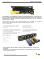
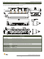
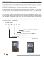
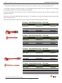
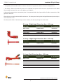
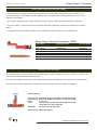
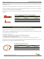
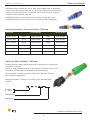
1
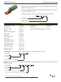
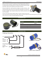
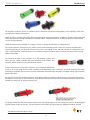
Cannon, VEAM, BIW
A Historical Achievement of Technology Leadership
Defining and Championing Innovation
Showcasing a portfolio of creativity, ITT’s “Engineered For Life” execution embraces products which
have become ubiquitous in a broad collection of markets including: Military/Aerospace, Civil Aircraft,
Industrial Instrumentation, Medical, Oil & Gas, Energy, Transportation, Telecom/Handset, Computer,
Consumer, and Automotive.
ITT’s rich interconnect history embraces contributions to both technological breakthroughs and social
movements. With one of the industry’s broadest product offerings, ITT’s interconnect products have
supported:
•
Every Free World space mission, bringing the universe to our doorstep.
•
Motion picture, radio, and television equipment, serving laughter and entertainment to millions.
•
Commercial and military communications systems, linking the voices of the world.
•
Computerized tools, reshaping the information highway.
•
Aircraft, rapid transit, and automobiles, mobilizing our expanding society.
•
Oil and natural gas production, powering the world’s economies.
•
Agricultural equipment, attacking the roots of world hunger.
www.ittcannon.com
ITT Interconnect Solutions
ITT Interconnect Solutions is a division of the multinational ITT Corporation, a $11.6 billion dollar global
enterprise representing the brands Cannon, VEAM,
and BIW. Our connector portfolio remains the most
extensive in the industry offering the most reliable and
cost effective range of interconnect solutions. These
innovations have enabled ITT to provide products and
technologies to such markets as:
advanced manufacturing facilities allows ITT to offer
products at market driven prices. Our capabilities,
especially in robotics, computerized precision tooling,
Kaizen Project Management, Six Sigma tools, and
testing, give ITT the most optimized global manufacturing footprint in the interconnect industry.
The Custom Difference
•
•
•
•
•
•
•
Automotive
Computer/Consumer
Industrial/Instrumentation
Military/Aerospace
Oil Fields
Telecom/Handset
Transportation
When you specify a Cannon, VEAM or BIW connector,
you can rely on a product designed, developed, and
manufactured to the highest quality and reliability
standards. This tradition of excellence is based on ITT’s
corporate culture of operating its businesses under the
principles of Six Sigma. At ITT, Six Sigma
is not just a quality philosophy but a complete
corporate culture that drives the entire business. Our
Value Based Management and Value Based Product
Development systems are two cornerstones that allow
for the development of both leadership and product
engineering principles, ensuring the correct industry
leading products are developed to the accepted
market driven lead times. These principles have
allowed ITT to become the market leader in all of our
business portfolios.
Six Sigma Manufacturing
ITT operates manufacturing facilities in the United
States, Germany, Italy, Mexico, China, Japan and the
UK, all of which have particular product area strengths
allowing ITT to offer a truly global footprint to our
customers. Our facilities are world class and
accommodate full vertical integration utilizing the latest
manufacturing technologies including: automated and
robotic machining centers, Super Market manufacturing
cells, Kanban pull systems, and automated electrical,
mechanical, and optical test and inspection equipment.
The combination of our manufacturing strength and our
As the industry leader in harsh environment interconnect applications, ITT’s world class engineering teams
will work directly with our customers to design and
develop cost effective solutions for their applications.
In many cases we may modify one of our standard
designs to ensure a highly reliable solution where
timing is critical. Yet, in those cases where a complete
custom interconnect solution is required, ITT will work
with our customer’s Engineers to design an interconnect solution which will be cost effective yet highly
reliable. As professional consultants, our Engineering
teams will provide a thorough systems and mechanical
analysis of any proposed solution. These analyses
provide our customers with sophisticated electrical
signal and mechanical characterizations to determine
the best solution for their application.
RoHS Compliance Information
ITT has implemented a strict parts control plan for all
ITT electronics plants worldwide that allows the
Cannon, VEAM, and BIW connector product portfolios
to meet the requirements of European Union Directive
2002/95/EC better know as the Reduction of
Hazardous Substances initiative. As appropriate,
specific Cannon, VEAM, and BIW products may be
ordered with an R prefix number which insures our customers will receive RoHS compliant parts for their commercial electronics applications and equipment. Since
most RoHS hazardous substances center around specific metal plating and lead solder coatings, ITT's products for RoHS compliance are available in the following
plating finishes: electroless nickel, stainless steel,
Anodize over aluminum and Gold plating. It should be
noted that gold plating would be recommended as the
replacement for tin-lead solder when ordering board mount connectors.
www.ittcannon.com
3
VEAM PowerLock
PowerLock Applications
The VEAM PowerLock connector series for field installation power distribution systems offers the ultimate in safety and reliability under the most severe operating conditions.
PowerLock is available in four standard formats which allow complete hook up through the standard
daisy chain principle. There are two Source connectors, one for panel mounting and one for cable
attachment. These are identified as Panel Source and Line Source. The other two types are Drain connectors. These connectors are identified as Panel Drain and Line Drain.
Typical applications for PowerLock include three phase motors, generators, load banks, lighting distribution panels and in-house supplies. PowerLock connectors serve a very diverse industry base which
includes
outdoor concerts, carnivals, sporting events, television outdoor broadcast, theatres, electricity supply
companies and many heavy industrial environments such as construction.
Reliable connections for field
installation power distribution
systems such as mobile generators.
Wind turbine and alternative energy power
transfer systems.
www.ittcannon.com
4
VEAM PowerLock
PowerLock Applications
We offer a wide variety of devices
for electricity supply companies.
Fuse carriers with integrated
PowerLock connectors provide a
safe and efficient connection to a
power distribution board.
Insulated rotary clamps provide
a compact connection to a
slotted busbar.
Insulated G-Style clamps for direct
connection to a live low voltage busbar.
www.ittcannon.com
5
In addition to our PowerLock series, we also
offer these connectivity solutions:
Harsh environments
Cannon APD
Cannon CA-Bayonet
In-line and bulkhead connectors resistant to harsh environmental conditions
(contaminants, vibration and shock).
Signal and power connectors with exceptional sealing against the ingress of fluids
and will withstand the effects of high vibrations.
Audio
VEAM CIR-LK
Quick coupling and uncoupling. High
impact heavy duty coupling mechanism. Bayonet connector for audio
applications, 4 to 53 channels.
VEAM VSC
Entertainment & Lighting
Heavy duty ribbed
coupling ring.
Extended female
ground contacts for
first mate, last break.
Threaded circular
19-pin connector
with replaceable
crimp or solder contacts.
VEAM TOURLOCK
Intermateable connectors with CIR-LK
series, higher resistance to the physical
shocks and tearings. IP67 protection.
www.ittcannon.com
6
VEAM PowerLock
Table of Contents
Applications . . . . . . . . . . . . . . . . . . . . . . . . . . . . . . . . . . . . . . . . . . . . . . .4-5
ITT Products . . . . . . . . . . . . . . . . . . . . . . . . . . . . . . . . . . . . . . . . . . . . . . .6
Introduction . . . . . . . . . . . . . . . . . . . . . . . . . . . . . . . . . . . . . . . . . . . . . . .8
PowerLock locking system . . . . . . . . . . . . . . . . . . . . . . . . . . . . . . . . . .9
Specifications . . . . . . . . . . . . . . . . . . . . . . . . . . . . . . . . . . . . . . . . . . . . .11
How to Order . . . . . . . . . . . . . . . . . . . . . . . . . . . . . . . . . . . . . . . . . . . . . .12
PowerLock Connectors . . . . . . . . . . . . . . . . . . . . . . . . . . . . . . . . . . . . . .12-16
PowerLock sequential mating boxes . . . . . . . . . . . . . . . . . . . . . . . . . .17-22
Steel Cabinets . . . . . . . . . . . . . . . . . . . . . . . . . . . . . . . . . . . . . . . . . . . . .23
Insulated G Clamps . . . . . . . . . . . . . . . . . . . . . . . . . . . . . . . . . . . . . . . . .24-25
Insulated Horizontal Clamps . . . . . . . . . . . . . . . . . . . . . . . . . . . . . . . . .26
Insulated Rotary Clamp . . . . . . . . . . . . . . . . . . . . . . . . . . . . . . . . . . . . .27
Insulated T Connector . . . . . . . . . . . . . . . . . . . . . . . . . . . . . . . . . . . . . . .27
Insulated Overhead Connector . . . . . . . . . . . . . . . . . . . . . . . . . . . . . . .28
Insulated Underground Connector . . . . . . . . . . . . . . . . . . . . . . . . . . . .28
Cable Lug Converters . . . . . . . . . . . . . . . . . . . . . . . . . . . . . . . . . . . . . .29
PowerLock Lug Connector . . . . . . . . . . . . . . . . . . . . . . . . . . . . . . . . . .30
Replacement Parts . . . . . . . . . . . . . . . . . . . . . . . . . . . . . . . . . . . . . . . . .30
Sealing Caps . . . . . . . . . . . . . . . . . . . . . . . . . . . . . . . . . . . . . . . . . . . . . .31
Fuse Carrier with Integral Connector Input . . . . . . . . . . . . . . . . . . . . .32
DIN Fuse Carrier Adaptor . . . . . . . . . . . . . . . . . . . . . . . . . . . . . . . . . . . .33
Screw in End Cap . . . . . . . . . . . . . . . . . . . . . . . . . . . . . . . . . . . . . . . . . .33
Snaplock Connectors . . . . . . . . . . . . . . . . . . . . . . . . . . . . . . . . . . . . . . .34-37
Tooling . . . . . . . . . . . . . . . . . . . . . . . . . . . . . . . . . . . . . . . . . . . . . . . . . . .38
Safety Information . . . . . . . . . . . . . . . . . . . . . . . . . . . . . . . . . . . . . . . . .40
www.ittcannon.com
7
Introduction
VEAM PowerLock
ITTVeamPowerLockconnectorsareplasticbodiedsinglepoleelectricalconnectorsused
in high current applications. For use in single and polyphase power distribution
systemsupto660amps,therangeincludespanelandcablemountedconnectors, and associated accessories. PowerLock connectors are moisture and
impact resistant and feature insulated contact tips to prevent accidental
touching of electrically live parts. Typical uses include 3 phase motors,
generators,windturbinesandpowerdistributionboardsinawidevarietyof
applications.
PowerLockconnectorsareeasytoterminatetocoppercableusingeitherindustrystandardcrimptoolsorset-screw
contacts.Thesilverplatedcontactsareavailablein2continuouscurrentranges,thosewithbrasscontactsare
suitableforuseupto400ampsandthosewithcoppercontactsupto660amps.
The high impact plastic connector bodies are keyed to prevent connection errors, and color coded to suit 3 phase
electricalsystemsthatareusedintheUS,EuropeandAustralia.
Ground
Neutral
Line 1
Line 2
Line 3
Europe
North America
Australia
*OldUKcolorsavailableonrequest
Connectorsforattachmentdirectlytocable(lineconnectors)aresuppliedwithaloosecontact.Fittingtothecableis
byeithercrimporset-screwtermination,thecontactisthenretainedwithintheinsulatorbodywithanyloncotterpin.
Securecouplingofaconnectorpairisthroughabayonetlocktogetherwithasecondarylockingpin.Thesecondarylock
engageswhenthebayonetlockisfullyturnedanddisconnectionrequiresasimplereleasekey.Thesecondarylockdiscouragestamperingandreducestheriskofaccidentalorunauthoriseddisconnection.Iffastdisconnectionisrequired,
foranapplicationwheretamperingisnotarisk,theconnectorscanbefittedwithaslidingcollarthatquicklyunlocks
theconnectors.
Cableconnectorsarefittedwithcableglandstofitawiderangeofcables.Thecableglands,togetherwithaninterfacialseal,provideaningressprotectionlevelofIP67whenmated.
Features & Benefits
Typical Applications
•
•
•
•
•
•
•
•
•
•
•
•
•
400ampor660ampcontinuouspowerratings
ColoredandKeyedtoensurecorrectmating
AllconnectorsIP2Xfingerprotected
CrimporSet-screwcableattachment
EnvironmentallysealedtoIP67
Secondarylockforaddedsecurity
Generators&LoadBanks
3PhaseMotors
FieldCamps
Back-uppowersystems
Powerdistributionpanels
Outdoorevents
WindTurbines
VEAM PowerLock
Connector locking
PowerLockconnectorsfeatureabayonetcouplingmechanismwithasecondarylockingpin.Whenapairofconnectors
arematedandfullyturnedtoengagethebayonet,thespringloadedsecondarylockingpinontheDrainconnectors,
snapsintoaslotontheSourceconnector;aspecialreleasekeyisthenrequiredtouncoupletheconnectors.
Coupling
Un-Coupling
Uncoupled - Note the secondary locking pin on the
right hand connector and
the slot on the left hand
connector.
Touncouple,therelease
key,LL0023Nispushed
intotheslot.
Aligningthearrowlinesup
the keyways allowing the
connectors to be pushed
together fully compressing
thelockingpin.
Thereleasekeyisused
topushthelockingpin
outoftheslot.
Connectors are turned
clockwise and locking pin
snaps into the slot on the
matinghalf.
With the release key
holdingthelockingpin
back, the connectors
can now be turned
counter-clockwise and
uncoupled.
ReleaseKey
LL0023N
OrderCode-AN389900010
Connector Descriptions
Source –thisthetermusedtodescribetheconnectorfittedwithamalecontactinafemalehousing,itisusuallythe
connectorattachedtothesourceofthepower,i.e.the‘live’connector,thecontactisfittedwithaninsulatedendcap
topreventaccidentalfingertouchingofliveparts.
Drain – thisisthetermusedtodescribetheconnectorfittedwithafemalecontactinamalehousing,thisisnotnormallytheliveconnector,howeveritdoesincludeaspringloadedinsulatedcaptopreventfingertouching.
TheDrainconnectorisfittedwithasecondarylockingpinthatlocksintothematinghalfwhenthe2connectorsare
fullyengaged.Asimplereleasekeyisrequiredtodisconnecttheparts.
Line –Thelineconnectoristhefreeconnectorfittedtoacable.CrimporSet-Screwcontactsareavailableforattachingtheconductor.
Panel –Panelconnectorsfeatureasquare4holeflangeforattachingtoapanel.The4holesarenormallysupplied
open,howevercanbepre-fittedwiththreadedinsertstoreducemountingtime.
www.ittcannon.com
9
Specifications
VEAM PowerLock
Electrical
Number of Contacts
SinglePole
Current Rating
400ampor660ampcontinuous
Operating Voltage
1000VAC/1500VDC
Test Voltage
4500VAC
Short Circuit Rating
16kAfor1s,34kApeak
Insulation Resistance
>5000Mohm
Electrical Protection
IP2XFingertouchprotected
Contact Resistance
<0.1mOhm
Mechanical
Contact Material
Brass(400amp)orCopper(660amp),SilverPlated
Housing Material
HighTemperatureThermoplastic
Locking
Bayonetwithsecondarylockingpin
Mating Cycles
500
Contact Type
SetScrew(400amp)orCrimp(660amp)
Contact to Housing Retention
NylonCotterPin
Cable Retention
Cableglandnut
Vibration
10-2000Hz/15g
Environmental
Operating Temperature
-30°Cto+125°C(-22°Fto+257°F)
Ingress Protection
IP67whenmated
Flammability
UL94-V0
RoHS
Compliant
Listing and Approvals
PowerLockconnectorsaretestedandcertifiedbyVDE
SelectedPowerLockproductsarelistedbyULandapprovedforuseinNorthAmerica,
forfurtherdetailscontactITT,InterconnectSolutions.
PowerLockconnectorsaremanufacturedandtestedasrequiredtocarryEuropeanCE
marking.
Safety Note: PowerLock connectors and related products should only be installed
and handled by suitable qualified persons.
Specifications and dimensions subject to change
www.ittcannon.com
10
VEAM PowerLock
How to Order
Body
Style
Example = NLDFT
Description
Code
Line Source
Line Drain
Panel Source
Panel Drain
NLS
NLDFT
NPS
NPDFT
Ground / Green
Neutral / Blue
Neutral / White
Neutral / Black
Line 1 / Brown
Line 1 / Black
Line 1 / Red
Line 2 / Black
Line 2 / Red
Line 2 / White
Line 3 / Grey
Line 3 / Blue
E-GN
N-BL
N-W
N-BK
1-BN
1-BK
1-R
2-BK
2-R
2-W
3-GY
3-BL
Use with NLDFT & NPDFT L
Leave blank for NLS & NPS
Crimp 300mm² copper cable*
Crimp 240mm² copper cable*
Crimp 185mm² copper cable*
Crimp 150mm² copper cable*
Crimp 120mm² copper cable*
Crimp 107mm² copper cable*
Crimp 95mm² copper cable*
Crimp 70mm² copper cable*
Crimp 50mm² copper cable*
Crimp 35mm² copper cable*
Set Screw 120 mm² (See Note)
M12 Threaded post 400amp
M12 Threaded post 660amp
M12 Threaded hole 400amp
M12 Threaded hole 660amp
Gland
Gland
Gland
Gland
nut
nut
nut
nut
15-23mm
19-28mm
22-32mm
30-38mm
Ø
Ø
Ø
Ø
Sliding Collar (Source only)
Hand Grip (Line only)
No Flange (Panel only)
M6 threaded insert front
M6 threaded insert rear
Line/Phase
Color
— E-GN —
L
Contact
Cable
Special
Type
Gland
Option
— C240
— M40B — HG
IMPORTANT SAFETY INFORMATION
Standard PowerLock and
SnapLock contact are copper
based contacts, they should not
be used for direct termination
onto aluminum cables as galvanic corrosion and overheating
can occur. If you intend to use
aluminum cables please contact
ITT for advice on alternatives to
the standard copper contacts.
NPDFT & NLDFT only
C300
C240
C185
C150
C120
C107
C95
C70
C50
C35
S120
T4
T6
H4
H6
M40S
M40A
M40B
M50
NLS & NLDFT only
NPS & NPDFT only
NPS only
NOTE –
When using S120 contact with
smaller cables, a reduction kit is
required. Each kit contains a series
of sleeves to suit the cable size.
NLS & NLDFT only
SC
HG
NF
M6F
M6R
Release Key
Order Code -AN389900010
* For aluminium cable, please contact ITT Veam /
Cannon or our local distributor
Specifications and dimensions subject to change
www.ittcannon.com
11
Cable size
Kit order code
95mm²
70mm²
50mm²
35mm²
25mm²
A3099000100
A00602825
A00602831
A00602840
A00602830
cable
cable
cable
cable
cable
Line Source
VEAM PowerLock
LineSourceistheconnectorwithamalecontactwhichisnormallyconnectedtothesourceofthepower.The
contactsarefittedwithaplasticendcapthatpreventsaccidentalfingertouchingoflivepartsoftheconnector
andmeetsIP2Xrequirements.Differentcontactsareavailabletosuitcableconductorsfrom25mm²to300mm².
Connectors rated either 400 amp or 660 amp, can be fitted to a wide range of
coppercables,andtoaluminiumcablesonrequest.
The 400 amp connectors use a standard set-screw contact suitable for 120mm²
conductors; when using smaller conductors a range of reduction sleeves are
available to order separately that can be used with cables down to 25mm², see
page11forfurtherinformation.
660 amp contacts are crimped using industry standard crimping tools and dies, a
rangeofcontactsareavailabletosuitcablesfrom35mm²to300mm²
CableglandsmeetingIP67requirementsarefittedtotheconnectors,4sizesareavailablethatcoverarangeof
cables with outside diameters from 15mm to 38mm. When selecting the M50 gland, please note that this is
suppliedwithanadaptor(notshownabove)thatstepstheconnectorupfromM40toM50.
A Sliding Collar can be factory fitted to the source
connector which allows a pair of connectors to be
disconnected without the use of a separate release
key.
Rubber hand grips are available that fit over the
ribbedsectionofthemaininsulatorbody,thesegrips
assistwiththehandlingoftheconnectorswhenbeing
usedindifficultconditions.
Ordersuffix=HG
Ordersuffix=SC
Orderinginformation–seepage11forfulldetailsoftheoptionsavailable
Examplepartnumber:
NLS-1-BN-S120-M40A
NLS – X – XX – XXXX – MXXX – XX
Line & Color
Contact
Cable Gland
Special Options
HG
SC
Hand Grip
Sliding Collar
Specifications and dimensions subject to change
www.ittcannon.com
12
Line Drain
VEAM PowerLock
LineDrainistheconnectorwithafemalecontactwhichisnotnormallythelivepart,howevertheyarefittedwith
aspringloadedplasticcapthatpreventsaccidentalfingertouchingofthecontact,andtheconnectormeetsIP2X
requirements.Contactsareavailabletosuitcableconductorsfrom25mm²to300mm².
Connectors rated either 400 amp or 660 amp, can be fitted to a wide range of
coppercables,andtoaluminiumcablesonrequest.
The 400 amp connectors use a standard set-screw contact suitable for 120mm²
conductors;whenusingsmallerconductorsarangeofreductionsleevesareavailabletoorderseparatelythatcanbeusedwithcablesdownto25mm²,seepage11
forfurtherinformation.
660 amp contacts are crimped using industry standard crimping tools and dies, a
rangeofcontactsareavailabletosuitcablesfrom35mm²to300mm²
CableglandsmeetingIP67requirementsarefittedtotheconnectors,4sizesareavailablethatcoverarangeof
cables with outside diameters from 15mm to 38mm. When selecting the M50 gland, please note that this is
suppliedwithanadaptor(notshownabove)thatstepstheconnectorupfromM40toM50.
Rubber hand grips are available that fit over the
ribbedsectionofthemaininsulatorbody,thesegrips
assistwiththehandlingoftheconnectorswhenbeing
usedindifficultconditions.
The drain connector is fitted with a secondary locking
pin.Whenapairofconnectorsaremated,thesecondarylockingpinengageswithaslotinthesourceconnector that prevents the connectors from being uncoupled
without the use of a special release key, or when the
sourceconnectorisfittedwithaslidingcollar.
Ordersuffix=HG
Orderinginformation–seepage11forfulldetailsoftheoptionsavailable
Examplepartnumber:
NLDFT-2-BK-L-C185-M40B
NLDFT – X – XX – L - XXXX – MXXX – XX
Line & Color
Contact
Cable Gland Special Options
HG
Specifications and dimensions subject to change
www.ittcannon.com
13
Hand Grip
Panel Source
VEAM PowerLock
Threadedpostversionshown
42.50
Panel Source connectors are supplied fully assembled with the male contact
havinganM12threadedpost,withnutandspringwasherforconnectiontoa
standardcablelug,orM12threadedholeforfixingwithabolt.Theseconnectors
areratedeither400amp(T4/H4)or660amp(T6/H6).
42.50
The standard connector is mounted to a panel through 4 fixing holes on the
flange,panelcut-outdetailsareshownontheright.Asanalternative,theflange
holescanbepre-fittedwithM6threadedinsertsforeitherfrontorrearfixing,
add suffix M6F for front fitting or M6R for rear fitting (rear mounting may
obscuretheproductlabel,maximumpanelthickness4mm).
44.00
Neoprene Gaskets to seal the flange against a panel are available to order
separately,orderpartnumberA2499001150.
Ifrequired,theconnectorcanalsobesuppliedwithoutaflange(specialoption
suffix–NF).
ASlidingCollarcanbefittedtothe
source connector which allows a
pairofconnectorstobedisconnected without the use of a separate
releasekey.
4 HOLES ø 5.50mm
Panel Cutout
Threaded Insert
Ordersuffix=SC
Orderinginformation–seepage11forfulldetailsoftheoptionsavailable
Examplepartnumber:
NPS-N-BL-T4
NPS – X – XX – XX – XX
Gasket
Special Options
Line & Color Contact
M6F
M6R
NF
SC
M6 threaded insert front mounting
M6 threaded insert rear mounting
No Flange
Sliding Collar
Panel connectors can also be supplied with an un-assembled crimp or set-screw contact. In this case the
contactisfittedtothecable,andmustbeassembledtotheinsulatorbodybeforethefullyassembledconnectorisfittedtothepanel.Thisisanon-standardoption,pleasecontactyoursupplierforfurtherinformation.
Specifications and dimensions subject to change
www.ittcannon.com
14
Panel Drain
VEAM PowerLock
PanelDrainconnectorsaresuppliedfullyassembledwiththefemalecontacthavinganM12threadedpost,
withnutandspringwasherforconnectiontoastandardcablelug.Theseconnectorsratedeither400amp
(T4) or 660 amp (T6). This connector is fitted with the secondary locking pin for secure connections, see
explanationonLineDrainpage13.
42.50
47.00
42.50
Thestandardconnectorismountedtoapanelthrough4fixingholeson
theflange,panelcut-outdetailsareshownontheright.Asanalternative,
theflangeholescanbepre-fittedwithM6threadedinsertsforeitherfront
orrearfixing,addsuffixM6FforfrontfittingorM6Rforrearfitting(rear
mounting may obscure the product label, maximum panel thickness
4mm).
NeopreneGasketstosealtheflangeagainstapanelareavailabletoorder
separately,orderpartnumberA2499001150.
4 HOLES ø 5.50mm
Panel Cutout
Ifrequired,theconnectorcanalsobesupplied
withoutaflange(specialoptionsuffix–NF).
Gasket
Orderinginformation–seepage11forfulldetailsoftheoptionsavailable
Threaded Insert
NPDFT – X – XX – L – XX – XXX
Examplepartnumber:
NPDFT-3-BL-L-T6
Line & Color
Contact
Special Options
M6F
M6R
NF
M6 threaded insert front mounting
M6 threaded insert rear mounting
No Flange
Panelconnectorscanalsobesuppliedwith an un-assembled crimp or Set-Screw contact. In this case the
contact is fitted to the cable, and must be assembled to the insulator body before the fully assembled
connector is fitted to the panel. This is a non-standard option, please contact your supplier for further
information.
Specifications and dimensions subject to change
www.ittcannon.com
15
VEAM PowerLock
Panel Drain with Backshell
Panel Drain connectors (SKPP) can be supplied with a
backshell to provide a watertight fitting to the cable.
Theseconnectorsaresuppliedwithaloosefemalecontactthatisfittedtothecablebeforebeingassembledinto
theconnectorhousing.
Connectorsratedeither400ampor660amp,canbefittedtoawiderangeofcoppercables,andtoaluminium
cablesonrequest.
This connector is fitted with the secondary locking pin
for secure connections, see explanation on Line Drain
page13.
42.50
Thestandardconnectorismountedtoapanelthrough
4 fixing holes on the flange, panel cut-out details are
shownontheright.Asanalternative,theflangeholes
can be pre-fitted with M6 threaded inserts for either
front or rear fixing, add suffix M6F for front fitting or
M6R for rear fitting (rear mounting may obscure the
productlabel,maximumpanelthickness4mm).
42.50
47.00
NeopreneGasketstosealtheflangeagainstapanelarepre-fittedtothisstyle.
4 HOLES ø 5.50mm
Orderinginformation–seepage11forfulldetailsoftheoptionsavailable
NPDFT - X - XX - L - XXXXSKPP - MXXX - XX
Line & Color
Contact
Cable Gland
Special Options
M6F
M6R
M6 threaded insert front mounting
M6 threaded insert rear mounting
ExamplePartNumber:NPDFT-E-GN-L-SI20SKPP-M40A
Specifications and dimensions subject to change
www.ittcannon.com
16
Sequential Connecting Box
VEAM PowerLock
APowerLockBoxisa3phasehighpowerconnectingunit,usedasaterminationpointforpowercables.The
boxesincludeanumberofsafetyfeaturestopreventincorrectconnectionanddisconnection.AllPowerLock
devices are ‘keyed’ to eliminate the possibility of connecting with the wrong line, and color coded to suit
international3phasestandards.
Anywhere that you are unable to rely on a public utility power source, a PowerLock Box can provide a
connectionpointforamobilegenerator,intoyourlowvoltage(1500voltDC)network.
Features and Benefits
• Connectwithstandard‘Powerlock’connectors
• SequentialconnectingensuresGround/Earthis
connectedfirst
• 400amp&660ampcontinuouscurrentoptions
• ColorcodedtosuitEuropean,NorthAmerican,and
Australian3phasestandards
• SourceandDrain(PoweroutorPowerin)options
• Allports‘keyed’topreventincorrectconnection
• SealedSecuritylidoptional
• IP2XFingerprotected
• Locktopreventinterference
• 19”x2Urackmountingorflangemount
• Environmentallysealedconnectorportsto
protectionlevelIP65
Typical Applications
• MobileGenerators
• Powerforfieldcamps
• Hospitals
• Outdoorevents
• Weldingequipment
• Barrackblocks
• Docksidepowerplant
• DataandIntelligencecenters
• Bringinageneratorduringanemergency,connecttoaPowerLockBox,andyouarequicklyupand
runningagain
• Wheneveryouneedaflexiblesourceoflowvoltagepower,withaPowerLockBoxinstalled,youhavea
safeandsecureconnectionpoint.
Specifications and dimensions subject to change
www.ittcannon.com
17
VEAM Power Lock
Sequential Connecting Box
Technical Overview
ThePowerLockBoxisdesignedforuseinhighcurrentapplicationsandoffersmanysafetyandsecuritybenefitswhencomparedwithasetofindividualconnectors.
Performance
Current rating
400ampor660ampcontinuous
Voltage rating
1000VAC/1500VDC
Contact material
Brass(400amp)orCopper(660amp),silverplated
Housing material
Hightemperaturethermoplastic
Endurance
500connectioncycles
Environmental protection
Un-liddedversionIP65whenconnectorsarefitted
of connector ports
LiddedversionIP65withlidlockedorwhenconnectorsarefitted
Electrical protection
IP2X(fingersafe)
Flammability rating
UL94-V0
Operating temperature
-30ºCto+85ºC
Color coding
European,NorthAmerican&Australian3phasecolourcoding
RoHS & WEEE
Compliant
Safety notice
ThePowerLockBoxshouldonlybeinstalledandoperatedbysuitablyqualifiedpersons
Specifications and dimensions subject to change
www.ittcannon.com
18
Sequential Connecting Box
VEAM PowerLock
Mounting Options
ThePowerLockBoxisdesignedformountingto19”racksor
toapanelcutout.For19”rackmountingtheunitissuppliedtofita2Uspacing,andwhereanoverlapisrequired
forfittingtoapanelcutout,thePowerLockBoxcanbesuppliedwithaflange,makingtheoverallheight107mm.The
rearviewofaflangedversionisshown(right).
Operation of the PowerLock Box
EachconnectorporthasanM12threadedpostwithnutandspring
washerontherearforthefixedcablingofthePowerLockBox.In
additionthereisa3poleconnectorontherearofthebox,connectedtoamicro-switchthatisactivatedonceallcableconnectorsare
insertedintothePowerLockBox.Theboxisthenoperatedasfollows:
• Foraboxfittedwithasealedlid,firstunlockthelidusingthe
keyprovided,fortheun-liddedgostraighttothenextstep
• InserttheGround/Earthconnectorintothegreenportonthe
leftandturn45°totherighttolock
• Insertinsequence,fromlefttoright,theNeutralfollowedby
the3phases
• OncetheLine3connectorisinplace,usingthekeyprovided,
locktheboxasindicatedonthefrontpanel
• Theboxisnowconnectedandreadytobepoweredup
Never attempt to uncouple the connectors while under load.
PowerLock Sequential Connecting Box
Ordering Information
PBX—XX—XX—XX—XXX
Box
SL
SLF
NL
NLF
type
=SealedLid
=SealedLidwithFlange
=NoLid
=NoLidwithFlange
Example
A660ampboxwithasealedlidandDrain
contactswithEuropeancolorcodingis:
Contact type
PS=Source
PD=Drain
PBX-SL-PD-EU-660
Regional color code
EU=Europe
US=NorthAmerican
AU=Australia
Power rating
400=400amp
660=660amp
Specifications and dimensions subject to change
www.ittcannon.com
19
VEAM Power Lock
Steel Cabinets for PowerLock Box and NRG Box
ThePowerLockPowerDistributionCabinethasbeendesignedandtestedtoconformtotherequirementsforCEmarkingby
implementingtherequirementsoftheLowVoltageDirective(LVD)73/23/EECwhichisimplementedastheElectricalEquipment
(Safety)Regulations1994.
Itcomplieswiththefollowingspecifications:BSEN60439-1:1999,BSEN60439-5:1996andIEC60529:1992
Thecabinetisfittedwitheither1or2NRGorPowerLockBoxsequentialunitsratedat400Aor600A.Theseunitsallowsafe
connectioninthecorrectsequenceofPowerLockconnectors(Ground,Neutral,Phase1,Phase2,Phase3).Theunitincorporates a key lockable switch which can be connected to auxiliary safety circuits. Once locked, it prevents unmating of the
systembyunauthorizedpersonnel.
Thecabinetisfittedwithexternalaccessandblankingpanelswhicharedesignedtoaidintheroutingofcablesbothintoand
outofofthecabinet.Aninformationplateisfittedontothesideofthecabinetincorporatingdatafortraceability.Thecabinetdoorincorporates2doorlocks(triangularkeytype)forsecurity.Whenlatched,thecabinethasanIP34Denvironmental
rating.Foradditionalsecurity,apadlockcanalsobefitted.Fixingplatesareprovidedtoenabletheunittobebesecurely
fixedduringinstallation,priortoelectricaloperation.
The cabinet is fitted with generic safety signs. These signs give warning of the potential electrical hazard, together with
mandatorysignsregardingcabinetsecurityandisolation.AllsignssuppliedconformtothecurrentrequirementsoftheHealth
andSafety(SafetySignsandSignals)Regulations.
Part Number Structure
ENC -
1AU 2AU 1EU
2EU
1US
2US
400
600
- BCE - PS - PBX
- TCE - PD
- NBB
PBXforPowerLockBoxes,leaveblankforNRG’s
PanelSourceorPanelDrain
BottomCableEntry,TopCable EntryorNoBusBars
400or600AmpNRGboxes
NumberofNRG/PBXboxesandcolorcoding-AU-Australia
EU-Europe
US-NorthAmerica
Specifications and dimensions subject to change
www.ittcannon.com
20
Insulated G Style Clamp
VEAM PowerLock
• Completelyinsulatedwhichallowsfordirectconnectionofageneratorcabletoalivelowvoltagebusbar.
• TheclampisfixedtothebusbarbymeansofaninsulatedboxspannerwhichmeetstherequirementsofIEC60900
(liveworking,handtoolsforuseupto1000Vacand1500Vdc).
APowerLockgeneratorinputconnectionpointisincorporatedwithintheclamptoallowfordirectconnectionofthe
generatorcableend.
Thesedevicesareratedat400Aand660Acontinuous.Theclampsarealsokeyedtodistinguishbetweenphasesand
preventconnectionerrors.
Theclampheadwidthofthe400ampversionsis28mm,the660ampclampsare45mmwide.
G clamp - Short Extension Arm - 400 amp
Line / Color
Description Code
ITT Part Number
Earth / Green
LVB100-E-GN-S
078214-6404
Neutral / Blue
Line 1 / Brown
Line 2 / Black
Line 3 / Grey
Installation Tool
LVB100-N-BL-S
LVB100-1-BN-S
LVB100-2-BK-S
LVB100-3-GY-S
LVS200H
078214-6403
078214-6400
078214-6401
078214-6402
A00044028
G clamp - Short Extension Arm - 660 amp
Line / Color
Description Code
Earth / Green
Neutral / Blue
Line 1 / Brown
Line 2 / Black
Line 3 / Grey
Installation Tool
LVB200-E-GN-S
LVB200-N-BL-S
LVB200-1-BN-S
LVB200-2-BK-S
LVB200-3-GY-S
LVS200H
ITT Part Number
A00044S2E
A00045S2N
A00045S21
A00045S22
078214-6000
A00044028
G clamp - Long Extension Arm - 400 amp
Line / Color
Description Code
ITT Part Number
Earth / Green
LVB100-E-GN-E
078214-6414
Neutral / Blue
Line 1 / Brown
LVB100-N-BL-E
LVB100-1-BN-E
078214-6413
078214-6410
Line 2 / Black
Line 3 / Grey
Installation Tool
LVB100-2-BK-S
LVB100-3-GY-E
LVL200H
078214-6411
078214-6412
A00044027
G clamp - Long Extension Arm - 660 amp
Line / Color
Description Code
Earth / Green
Neutral / Blue
Line 1 / Brown
Line 2 / Black
Line 3 / Grey
Installation Tool
LVB200-E-GN-E
LVB200-N-BL-E
LVB200-1-BN-E
LVB200-2-BK-E
LVB200-3-GY-E
LVL200H
Specifications and dimensions subject to change
www.ittcannon.com
21
ITT Part Number
A00044E2E
A00044E3N
A00044E31
A00044E32
A00044E43
A00044027
Insulated G Style Clamp
VEAM PowerLock
• Completelyinsulatedwhichallowsfordirectconnectionofageneratorcabletoalivelowvoltagebusbar.
• TheclampisfixedtothebusbarbymeansofaninsulatedboxspannerwhichmeetstherequirementsofIEC60900
(liveworking,handtoolsforuseupto1000Vacand1500Vdc).
APowerLockgeneratorinputconnectionpointisincorporatedwithintheclamptoallowfordirectconnectionofthe
generatorcableend.
Thesedevicesareratedat400and660Acontinuous.Theclampsarealsokeyedtodistinguishbetweenphasesandpreventconnectionerrors.
Theclampheadwidthofthe400ampversionsis28mm,the660ampclampsare45mmwide.
G clamp - Right Angle Extension Arm - 400 amp
Line / Color
Description Code
ITT Part Number
Earth / Green
LVB100-E-GN-R
078214-6424
Neutral / Blue
Line 1 / Brown
Line 2 / Black
Line 3 / Grey
Installation Tool
LVB100-N-BL-R
LVB100-1-BN-R
LVB100-2-BK-R
LVB100-3-GY-R
LVS200H
078214-6423
078214-6420
078214-6421
078214-6422
A00044028
G clamp - Right Angle Extention Arm - 660 amp
Line / Color
Description Code
ITT Part Number
Earth / Green
LVB200-E-GN-R
A00044R2E
Neutral / Blue
Line 1 / Brown
Line 2 / Black
Line 3 / Grey
Installation Tool
LVB200-N-BL-R
LVB200-1-BN-R
LVB200-2-BK-R
LVB200-3-GY-R
LVS200H
078214-6023
078214-6020
078214-6021
078214-6022
A00044028
G clamp -Dual Extension Arm - 660 amp
Line / Color
Description Code
ITT Part Number
Earth / Green
LVB1200-E-GN
078214-6114
Neutral / Blue
Line 1 / Brown
LVB1200-N-BL
LVB1200-1-BN
078214-6113
078214-6110
Line 2 / Black
Line 3 / Grey
LVB1200-2-BK
LVB1200-3-GY
078214-6111
078214-6112
Installation Tool
LVL200H
A00044027
Specifications and dimensions subject to change
www.ittcannon.com
22
Insulated Horizontal Clamp
VEAM PowerLock
• Completelyinsulatedwhichallowsfordirectconnectionofageneratorcabletoalivelowvoltagebusbar.
• TheclampisfixedtothebusbarbymeansofaninsulatedboxspannerwhichmeetstherequirementsofIEC60900
(liveworking,handtoolsforuseupto1000Vacand1500Vdc).
APowerLockgeneratorinputconnectionpointisincorporatedwithintheclamptoallowfordirectconnectionofthe
generatorcableend.
These devices are rated at 660A continuous. The clamps are also keyed to distinguish between phases and prevent
connectionerrors.
Horizontal Clamp - Short Extention Arm - 660 amp
Line / Color
Description Code
Earth / Green
Neutral / Blue
Line 1 / Brown
Line 2 / Black
Line 3 / Grey
Installation Tool
LVK600-E-GN-S
LVK600-N-BL-S
LVK600-1-BN-S
LVK600-2-BK-S
LVK600-3-GY-S
LVS200H
ITT Part Number
A00044S8E
078214-6213
078214-6210
078214-6211
078214-6212
A00044028
Horizontal Clamp - Long Extention Arm - 660 amp
Line / Color
Description Code
Earth / Green
Neutral / Blue
Line 1 / Brown
Line 2 / Black
Line 3 / Grey
Installation Tool
LVK600-E-GN-E
LVK600-N-BL-E
LVK600-1-BN-E
LVK600-2-BK-E
LVK600-3-GY-E
LVL200H
ITT Part Number
078214-6204
078214-6203
078214-6200
078214-6201
078214-6202
A00044027
Horizontal Clamp - Long Extention Arm - 660 amp
Line / Color
Description Code
Earth / Green
Neutral / Blue
Line 1 / Brown
Line 2 / Black
Line 3 / Grey
Installation Tool
LVK600-E-GN-R
LVK600-N-BL-R
LVK600-1-BN-R
LVK600-2-BK-R
LVK600-3-GY-R
LVS200H
Specifications and dimensions subject to change
www.ittcannon.com
23
ITT Part Number
A00044R8E
A00044R9N
A00044R91
A00044R92
A00044R95
A00044028
Rotary Clamp / T Connector
VEAM PowerLock
Rotary Clamp / Generator Connector (FRED)
• CompactunitincorporatesaLineSourceFingerProofconnectorwitharotarytypeclamp,suitableforuse
onslottedBus-bars.ThehandlemeetstherequirementsofIEC60900(liveworking,handtoolsforuseupto
1000Vacand1500Vdc).
• Theclampismanufacturedinhighconductivitymaterialandissuitablefor660Acontinuousoperation.
• Therotarywheelismanufacturedfromhardenedsteelwhicheliminatesproblemsassociatedwithholeelongation.
• Anergonomicfullyinsulatedinstallationtoolisavailableforfixingtheclamptoaslottedbus-bar.
Rotary Clamp / Generator Connector (FRED)
Line / Color
Description Code
ITT Part Number
Earth / Green
Neutral / Blue
Line 1 / Brown
Line 2 / Black
Line 3 / Grey
Installation Tool
LVE500-E-GN
LVE500-N-BL
LVE500-1-BN
LVE500-2-BK
LVE500-3-GY
LVE500H
A00044055
078214-6103
078214-6100
078214-6101
078214-6102
A00044054
Insulated T-Piece Connector
TheinsulatedT-Piececonnectorallowstheusertheoptiontosplitonephaseintotwoorcombinetwophasesinto
onebythequickestandsafestpossiblemeans.
TheInputandOutputconnectorsarecolorcodedandmechanicallykeyedthesametopreventconnectionerrors.
AllconnectorsareIPX2ratedwhenun-matedandcomewiththeSecondaryLockingasstandard.
Position A
Order Information
Position A (x1):
Position B (x2):
Phase:
Color:
Position B
Amperage:
Panel Drain Finger Proof (PDFT) or Panel Source (PS)
Panel Drain Finger Proof (PDFT) or Panel Source (PS)
1, 2, 3, N, E
Red (R), Yellow (Y), Blue (BL), Black (BK), Green (GN)
Brown (BN), Grey (GY), White (W)
400 Amps (T4), 660 Amps (T6)
Version shown: APDFT-BPS-3-BL-T4
Specifications and dimensions subject to change
www.ittcannon.com
24
Insulated Generator Connectors
VEAM PowerLock
ThiscompactunitincorporatesaPowerLockgeneratorinputconnectionpointwitharearterminationareatoaccept
solidalloycablecores.
Thisenablesatemporarymobilegeneratortobeconnectedtoanundergroundcablewhenrepairworkisundertaken.
Thecableisexcavated,cutandthePowerLockconnectorthenfittedtothecablecoresvia2setscrews.Thegenerator
cableendcanthendirectlylinkintotheundergroundcable.
After completion of the repair, the PowerLockfittings are simply removed and the main cable spliced using existing
methods.
Insulated Underground Cable Generator Connector
Line / Color
Description Code
Neutral / Blue
Line 1 / Brown
Line 2 / Black
Line 3 / Grey
Ratchet Tool
LVJ900-N-BL
LVJ900-1-BN
LVJ900-2-BK
LVJ900-3-GY
LVJ900H
ITT Part Number
078214-9033
078214-9030
078214-9031
078214-9032
A0004406H
Insulated Overhead Line Clamp / Generator Connector
ThisdeviceallowsfordirectconnectionofageneratorunittoLowVoltageoverheadlinesystems.
TheunitconsistsofaninsulatedLineClamp,3metersof50mm2flexiblecoppercableandaPowerLockgeneratorinput
cable,otherlengthsareavailableuponrequest.
Themethodsofconnectionis:
1.Thecopperoralloyoverheadwireiscleanedtoensuregoodconnectionpoints.
2.Theclampishookedontothewireandtightenedviatheinsulatedclampbody.
3.Theflexiblecableisthenstrappedtothepole.
4.Atthecableend,aPowerLockgeneratorconnectionpointisprovidedforconnectionofthegeneratorcable.
ThegeneratorconnectionpointoffersallstandardsafetyfeaturesassociatedwiththePowerLockrange,suchaskeysto
distinguishphases,IP67sealingandindividualphasecolorcoding.
Insulated Overhead Line Clamp
Line / Color
Description Code
ITT Part Number
Neutral / Blue
Line 1 / Brown
Line 2 / Black
Line 3 / Grey
LVF600-N-BL
LVF600-1-BN
LVF600-2-BK
LVF600-3-GY
078214-6303
078214-6300
078214-6301
078214-6302
Specifications and dimensions subject to change
www.ittcannon.com
25
Cable Lug Converter
VEAM PowerLock
TheMulti-ConverterenablesanyusertoeasilyconvertluggedcabletoPowerLock
withinminutesensuringallsafetyandsecurityofbasicPowerLockconnectorseries.
APowerLockconnectionpointisincorporatedwithintheunittoallowfordirect
connectionofthegeneratorcableend.
AvailableinbothSourceandDrainformats,thisdeviceassuresthecorrect
connectionwhetheritbePowerLockorLugtomaximizecablemanagement.
Cable Lug Converter - Source and Drain - 660 Amp
Line / Color
ITT Part Number
ITT Part Number
Earth/Green
Source
078214-9055
Drain
078214-9065
Neutral/Blue
Source
078214-9053
Drain
078214-9063
Line1/Brown
Source
078214-9050
Drain
078214-9060
Line2/Black
Source
078214-9051
Drain
078214-9061
Line3/Grey
Source
078214-9052
Drain
078214-9062
TighteningTool
274-7630-000
274-7630-000
Cable Lug - Mini Converter - 400 Amp
TheMiniConverterenablessmallercableswithacablelugtobeconvertedto
aPowerLockconnection.
The lug is simply attached directly to the PowerLock connector with a bolt
termination,andthecontactassembledintotheinsulatedbody.
This termination is suitable for smaller cables up to 400 amps in either
SourceorDrainconfiguration.
Orderinginformation-seepage11forfulllinecolorandcablegland
selection.
NLX - MC - X - XX - M40X
D - Drain
S - Source
Line and Color
Cable Gland
Specifications and dimensions subject to change
www.ittcannon.com
26
VEAM PowerLock
PowerLock Lug Connector
These devices allow for the conversion of PowerLock plug and socket system to a
standard nut and bolt fixing.
The units are simply connected to the PowerLock line connectors and locked to
avoid accidental disconnection.
Ordering information - see page 11 for full line color and color selection.
NPSNF - X - XX - XX - RA
Line and Color
Contact - T4 or T6
Miscellaneous Parts and Accessories
PowerLock Release Key - L0023N
AN389900010
S120 Cable Sleeve
AN3099000200
PowerLock Box Key
201-7535-000
Secondary Lock Kit
A00900100
NRG Box Key - Pack of 3
AN0000006
PowerLock Box Replacement Signal Connectors
320-7744-000
Hand Grip
317-7671-000
Gasket for PowerLock Panel mount
A2499001150
Cotter Pin NLDFT
A3299000500
Cotter Pin NLS
A3299000550
Cotter Pin NPDFT and NPS
A3299000100
Reduction Sleeves
See page 11
Gland nut M40S - PowerLock
368-7514-000
Gland nut M40A - PowerLock
368-7514-001
Gland nut M40B - PowerLock
368-7514-002
Gland nut M50 - PowerLock
368-7515-000
Gland nut 25S - Snaplock
5S1699000100
Gland nut 25L - Snaplock
AS1699000200
M40 to M50 adaptor
368-7516-000
Contact Kits - all contact kits contain a fully assembled contact and replacement cotter pin.
Order Code:
NLX - XXX - CONKIT
D - Drain
S - Source
Contact, see page 11 for options
Insulator Kits - all insulator kits contain a fully assembled insulator and replacement cotter pin. Kits only available for
M40 size insulators.
Order Code:
NLX - X-XX - XXX - M40 - INSKIT
D - Drain
S - Source
Line and Color, see page 11 for options
Current rating of contact being used - 400 or 660 amp
Specifications and dimensions subject to change
www.ittcannon.com
27
Sealing Cap
VEAM PowerLock
Whennotmated,theconnectorinterfacecanbeprotectedbyusingasealingcap.
Twotypesofcapareoffered,asimplesoftplasticcapprovidingIP53protectionand
anenvironmentallysealedrigidplasticcapwithIP67protectionandthesecondary
lockfeature,thesearecolorcodedtosuittheparentconnector.
Allcapsarefittedwithacordlanyardforsecuringtoit’sparentconnector.Cable
connectorshavealoopinthecordtofitaroundthecablegland,itisnecessaryto
specifythecableglandsizeinthepartnumberwhenorderingtoensurethecorrect
sizeloopissupplied.CapsforpanelconnectorshaveanM6ringterminalonthe
endofthelanyard.
CapsnotonlyofferprotectionagainstingressofmoistureanddirtintotheinterfaceofthePowerLockconnector,theyalsoofferadegreeofprotectionagainstmechanicaldamagethatcanbecaused
whenconnectorsoncablesarebeinghandledandtransported.
IP53 Protection Caps
Description
Order Code
Panel Drain
Panel Source
Line Drain with M40S and M40A gland
Line Drain with M40B gland
Line Source with M40S and M40A gland
Line Source with M40B gland
PCPD-5
PCPS-5
PCLD-5-M40A/S
PCLD-6-M40B
PCLS-5-M40A/S
PCLS-6-M40B
IP67 Protection Caps
Ordering Information
PCS - NLS - E-GN -
M40a/S
Cap
Style
PanelDrainNPD
PanelSourceNPS
LineDrainNLD
LineSourceNLS
Cap for Drain Connectors
Line / Phase Color
seepage11forselection
Cord Size
M40SandM40AM40A/S
M40BM40B
NLD & NLS only
Cap for Source Connectors
Specifications and dimensions subject to change
www.ittcannon.com
28
Fuse Carrier with Integral Generator Input Connector
VEAM PowerLock
JW4ST(3.625”/92mmpitch)fusecarrierwasdevelopedtoprovideasafeandefficientmeansofconnectingamobile
generatorsupplycabletofullyshroudedornon-shroudeddistributionboards.Theunitcomplieswiththe
requirementsofEATS37.2.
Thegeneratorcable(whenfittedwithPowerLockLineDraincablecoupler)canbepluggeddirectlyintotheFuseCarrier
andusedtofeedeithertheLowVoltagebus-barorfeedercircuit.
Thefusegeneratorconnectorisfingerprooftoavoidaccidentaltouchingofliveelements.
Theinputconnectorsarecolorcodedandmechanicallykeyedtopreventconnectionerrors.Line1unitswillonlyaccept
aLine1generatorconnector.
Theintegralgeneratorconnectoralsoacceptsgeneratorconnectorswiththepatentedsecondarylockingdevice
whicheliminatesthepotentialofaccidentaldisconnectionunderloadconditions.
BecausethisunitisdirectreplacementfortheexistingstandardJW4STfuseunit,itoffersasafe,fastandcost
effectivemethodofupgradingexistingdistributionboardstohavegeneratorinputpoints.Itisnotnecessarytomake
anymodificationstothecabinetotherthanremoveanexistingfusewayandreplacewiththeJW4STsystem.
JW4ST Fuse unit with PowerLock Connection point (JS)
Line / Color
Description Code
ITT Part Number
Neutral / Blue
Line 1 / Brown
Line 2 / Black
Line 3 / Grey
LVD400-N-BL
LVD400-1-BN
LVD400-2-BK
LVD400-3-GY
078214-9013
078214-9010
078214-9011
078214-9012
JW4ST82(3.25”/82mmpitch)fusecarrierwasdevelopedtoprovideasafeandefficientmeansofconnectingamobile
generatorsupplycabletofullyshroudedornon-shroudeddistributionboards.Theunitcomplieswiththerequirements
ofEATS37.2.
TheunitacceptstandardBS88-5fuses(notsupplied).
TheJW4ST82fuseunitalsoofferstheabilitytomakeadirectconnectiontomanypolemountedtransformerfuseunits.
JW4ST Fuse unit with PowerLock Connection point (JP)
Line / Color
Description Code
ITT Part Number
Neutral / Blue
Line 1 / Brown
Line 2 / Black
Line 3 / Grey
LVD401-N-BL
LVD401-1-BN
LVD401-2-BK
LVD401-3-GY
078214-9023
078214-9020
078214-9021
078214-9022
Specifications and dimensions subject to change
www.ittcannon.com
29
VEAM PowerLock
DIN Fuse Carrier Adaptor
ThisFusecarrieradaptorwasdevelopedtoprovideasafeandefficient
PowerLockconnectiontoDINfusecarrierrackswhicharemountedon
mostoftheEuropeanpowerdistributionboards.ThereareFullBlade
andHalfBladeversionsavailablewhichgivetheuseranoptiontoselect
whatsideneedstobefed.
Forpartnumbersandorderinginformation,pleasecontactITTVEAM/
Cannonorourlocaldistributor.
Screw In End Cap Fuse / Pole Mounted
Thisdeviceallowsfordirectconnectionofageneratorcabletoa
200Atransformerpolemountedfuseunit.Theexistingfuseunit
isunscrewedfromtheholderandreplacedwiththePowerLock
unit,whichincorporatesadummyfusetoallowfortheoutgoing
circuitonly.Thisenablesthegeneratorfeedcabletobedirectly
plugged into the pole mounted unit in order to feed the overheadLowVoltagetransmissionlines.
Line / Color
Description Code
Neutral / Blue
Line 1 / Brown
Line 2 / Black
Line 3 / Grey
LVC300-N-BL
LVC300-1-BN
LVC300-2-BK
LVC300-3-GY
ITT Part Number
078214-9043
078214-9040
078214-9041
078214-9042
Specifications and dimensions subject to change
www.ittcannon.com
30
Introduction
VEAM Snaplock
TheSnaplockconnectorseriesisaminiaturepowercablehookupsystemofferinghighcurrentcapabilitywhilemaintainingminimalphysicaldimensions.
Snaplockoffersacommerciallyviableoptiontohistoricalhardwiringtechniques.Inaddition,Snaplockoffersimproved
safetycharacteristicsthroughutilizationofinsulatedbodies,sealingmechanisms,lockingmechanismsandprotected
currentcarryingelements.
Snaplockconnectorsareavailableinarangeofcolorsforsimpleidentificationofindividuallines.
ThecontactelementsarebasedonourprovenLouvrebandtechnologywhichensureslowcontactresistancethus
minimizingpowerloss,lowphysicalinsertionforceswithaselfwipingaction,andhighnumberofmatingcycles.The
malecontactelementsareprotectedbyanon-conductivetipwhichmakesphysicalcontactwiththecurrentcarrying
elementimpossible.
The contacts are held in the insulators via a clip retention system. This
allows for fast, simple assembly and good retention of the contact sets,
especiallywherevibrationisanenvironmentalconcern.
Contact termination to the cable conductor is by standard compression
crimp or set-screw fixing and for panel mounting a threaded M12 post. Connectors for panel mounting and cable
mountingareavailable.AllconnectorsareIP67sealedwhenmatedthroughutilizationofintegralsealingringsandcable
glandstrainrelief.
Thespeedofconnectionanddisconnectionoffersgreatsavingsinequipmentdowntime,servicingandmaintenance
procedures.Thesecurityoftheconnectionismaintainedbyasimplebutveryeffectivelockingmechanismwhichcanbe
utilizedasatemporaryorsemi-permanentlock.
Thespringloadedslidelockfeatureshownabovelocksintobayonetgrooveonthematinghalf,andcanbedisengaged
byslidingbackusingonesthumb.Thislockfeaturecanbemadesemi-permanentbyslidingtheretainerforward.
Specifications and dimensions subject to change
www.ittcannon.com
31
VEAM Snaplock
How to Order
Example =
Description
Code
Panel Male - M12 post fixing
Panel Female - M12 post fixing
Panel Female with Cable Fixing
Cable Male - cable fixing
Cable Female - cable fixing
SNPM
SNPF
SNPFL
SNLM
SNLF
Body Contact
Contact Gland
Body
Style Gender
Size
Nut
Color
SNLM — P —
C50 — 25L — GN
IMPORTANT SAFETY INFORMATION
Standard PowerLock and
SnapLock contact are copper
based contacts, they should not
be used for direct termination
onto aluminum cables as galvanic corrosion and overheating
can occur. If you intend to use
aluminum cables please contact
ITT for advice on alternatives to
the standard copper contacts.
Male Contact (pin) use with SN..M P
Female Contact (skt) use with SN..F S
Crimp 70mm² Copper Cable
Crimp 50mm² Copper Cable
Crimp 35mm² Copper Cable
Crimp 25mm² Copper Cable
Set-Screw 70mm² Copper Cable
Set-Screw 50mm² Copper Cable
Set-Screw 35mm² Copper Cable
Set-Screw 25mm² Copper Cable
Threaded Post (Panel Mount)
C70*
C50*
C35
C25
S70*
S50*
S35
S25
TP
Gland nut 10-14mm Ø
Gland nut 13-18mm Ø
25S
25L
Red
Black
Green
Blue
Brown
Grey
White
Yellow
R
BK
GN
BL
BN
GY
W
Y
Cable fixing versions only
*C50, C70, S50 and S70 contacts can only be used with gland nut 25L
Specifications and dimensions subject to change
www.ittcannon.com
32
Specifications
VEAM Snaplock
Electrical
Number of Contacts
SinglePole
Current Rating
250ampcontinuous
Operating Voltage
1000VAC/1500VDC
Test Voltage
4500VAC
Dielectric Strength
4500VAC
Electrical Protection
IP2Xonmaleconnector
Contact Resistance
<0.1mOhm
Mechanical
Contact Material
Brass(Set-screw)orCopper(Crimp),SilverPlated
Housing Material
HighTemperatureThermoplastic
Locking
Bayonetwithslidelock
Vibration
10-2000Hz/15g
Mating Cycles
500
Contact Type
SetScreworCrimp
Contact to Housing retention
Cclip
Cable Retention
Cableglandnut
Environmental
Operating Temperature
-30°Cto+125°C(-22°Fto+257°C)
Ingress Protection
IP67whenmated
Flammability
UL94-V0
Cable Connectors
Male Cable Plug
OrdercodeSNLM-P-XXX-XXX-XX
Female Cable Socket
OrdercodeSNLF-S-XXX-XXX-XX
Cableconnectorsareavailablewithcontactstofitarangeofcableswithcentreconductorsfrom,25mm²to70mm²
Contactscanbespecifiedforeithercrimpingtocableorforset-screwfixing.
Glandnutsareofferedin2sizestosuitcableoveralldiametersfrom10mmto18mm.
Specifications and dimensions subject to change
www.ittcannon.com
33
Panel Connectors
VEAM Snaplock
Male Panel Plug
OrdercodeSNPM-P-TP-XX
Female Panel Socket
OrdercodeSNPF-S-TP-XX
Thestandardpanelconnectorsaremountedthrough4holesintheflange.TherearoftheconnectorhasanM12threadedpostfittedwithanutandlockwasher,totakeacablefittedwithastandardcablelug.Maleandfemaleconnectors
areavailableinarangeofcolors,andallpanelconnectorsarefittedwithagasket.
Themaleconnectorisfittedwithaslidinglatchtopreventaccidentaldisconnection.Thislatchcanbelockedinplace
tomakethisamorepermanentlock.
Thepanelfemaleconnectorcanalsobesuppliedwithacableglandnutfitting,thisversionusesacrimpedorset-screw
contact,thecontactsizeneedstobespecifiedwiththisitem.
Female Panel Socket with cable fixing
OrdercodeSNPFL-S-XXX-XXX-XX
Panel Cut out for all versions
Specifications and dimensions subject to change
www.ittcannon.com
34
Tooling
VEAM PowerLock and Snaplock
Crimp Tool - C130
000V74174
Crimp Tool with Case
274-7634-000
Crimp Tool with PowerLock Dies and Case
(Dies include - C50, C70, C95, C120, C150,
C185, C240 and C300)
320-7732-000
Crimp Tool with Snaplock Dies and Case
(Dies include - C25, C35, C50, and C70)
320-7731-000
Crimp Die C25 (30220)
995-7654-025
Crimp Die C35 (30221)
995-7654-035
Crimp Die C50 (30222)
995-7654-050
Crimp Die C70 (30223)
995-7654-070
Crimp Die C95 (30224)
995-7654-095
Crimp Die C120 (30235)
995-7654-120
Crimp Die C150 (30236)
995-7654-150
Crimp Die C185 (30237)
995-7654-185
Crimp Die C240 (30227)
995-7654-240
Crimp Die C300 (30229)
995-7654-300
PowerLock connector Release Key, L0023N
AN389900010
Snaplock contact insertion / male removal tool kit
500066100
Snaplock female contact removal tool
500066003
Snaplock Male Contact insertion/removal tool
500066002
Specifications and dimensions subject to change
www.ittcannon.com
35
Notes
Specifications and dimensions subject to change
www.ittcannon.com
36
Product Safety and Warranty
1. MATERIAL CONTENT AND PHYSICAL
FORM
Electrical connectors do not usually contain
hazardous materials. They contain conducting and non-conducting materials and can
be divided into two groups.
a) Printed circuit types and low cost audio
types which employ all plastic insulators and
casings.
b) Rugged, Fire Barrier and High Reliability
types with metal casings and either natural
rubber, synthetic rubber, plastic or glass
insulating materials. Contact materials vary
with type of connector and also application
and are usually manufactured from either:
Copper, copper alloys, nickel, alumel,
chromel or steel. In special applications,
other alloys may be specified.
2. FIRE CHARACTERISTICS AND ELECTRIC
SHOCK HAZARD
There is no fire hazard when the connector is correctly wired and used within the
specified parameters. Incorrect wiring or
assembly of the connector or careless use
of metal tools or conductive fluids, or
transit damage to any of the component
parts may cause electric shock or burns.
Live circuits must not be broken by separating mated connectors as this may
cause arcing, ionization and burning. Heat
dissipation is greater at maximum resistance
in a circuit. Hot spots may occur when resistance is raised locally by damage, e.g.
cracked or deformed contacts, broken
strands of wire. Local overheating may also
result from the use of the incorrect application tools or from poor quality soldering or
slack screw terminals. Overheating may
occur if the ratings in the product Data
Sheet/Catalog are exceeded and can cause
breakdown of insulation and hence electric
shock. If heating is allowed to continue it
intensifies by further increasing the local
resistance through loss of temper of spring
contacts, formation of oxide film on contacts and wires and leakage currents
through carbonization of insulation and
tracking paths. Fire can then result in the
presence of combustible materials and this
may release noxious fumes. Overheating
may not be visually apparent. Burns may
result from touching overheated components.
3. HANDLING
Care must be taken to avoid damage
to any component parts of electrical connectors during installation and use. Although
there are normally no sharp edges, care
must be taken when handling certain components to avoid injury to fingers. Electrical
connectors may be damaged in transit to the
customers, and damage may result in creation of hazards. Products should therefore
be examined prior to installation/use and
rejected if found to be damaged.
4. DISPOSAL
Incineration of certain materials may release
noxious or even toxic fumes.
5. APPLICATION
Connectors with exposed contacts should
not be selected for use on the current supply
side of an electrical circuit, because an electric shock could result from touching
exposed contacts on an unmated connector.
Voltages in excess of 30 V ac or 42.5 V dc are
potentially hazardous and care should be
taken to ensure that such voltages cannot be
transmitted in any way to exposed metal
parts of the connector body. The connector
and wiring should be checked, before making live, to have no damage to metal parts or
insulators, no solder blobs, loose strands,
conducting lubricants, swarf, or any other
undesired conducting particles. Circuit
resistance and continuity check should be
made to make certain that there are no high
resistance joints or spurious conducting
paths. Always use the correct application
tools as specified in the Data Sheet/Catalog.
Do not permit untrained personnel to wire,
assemble or tamper with connectors. For
operation voltage please see appropriate
national regulations.
IMPORTANT GENERAL INFORMATION
(i) Air and creepage paths/Operating voltage. The admissible operating voltages
depend on the individual applications and
the valid national and other applicable safety regulations.
For this reason the air and creepage path
data are only reference values. Observe
reduction of air and creepage paths due to
PC board and/or harnessing.
(ii) Temperature
All information given are temperature limits.
The operation temperature depends on the
individual application.
Product Warranty
A limited warranty applies to Cannon products. In general, except for obligations
assumed by Cannon under this warranty,
Cannon shall not be liable for any loss, damage, cost of repairs, incidental or consequential damages of any kind, whether or not
based on express or implied warranty, contract, negligence or strict liability arising in
connection with the design, manufacture,
sale, use or repair of the products. Product
availability, prices and delivery dates are
exclusively subject to our respective order
confirmation form; the same applies to
orders based on development samples
delivered. Please
refer
to
www.ittcannon.com (General Terms of Sale)
for the complete text of Cannon’s applicable
Terms and Conditions, including Warranty.
This publication is not to be construed as an
offer. It is intended merely as an invitation to
make an offer. By this publication, Cannon
does not assume responsibility or any liability for any patent infringements or other
rights of third parties which may result from
its use.
Reprinting this publication is generally permitted, indicating the source. However,
Cannon's prior consent must be obtained in
all cases. “Engineered for life” is a registered
trademark of ITT Corporation ©2006. All
other trademarks or registered trademarks
are property of their respective owners. All
dates subject to change without notice.
Commodities in this catalog may be
controlled for export by the International
Traffic in Arms Regulations (ITAR) and Export
Administration Regulations (EAR) when
specifically designed modified, or configured
for articles controlled by the United States
Government.
(iii) Other important information
Cannon continuously endeavors to improve
their products. Therefore, Cannon products
may deviate from the description, technical
data and shape as shown in this catalog and
data sheets.
ITT Interconnect Solutions, a Division of ITT
Corporation manufactures the highest quality products available in the marketplace;
however these products are intended to be
used in accordance with the specifications in
this publication. Any use or application that
deviates from the stated operating specifications is not recommended and may be
unsafe. No information and data contained
in this publication shall be construed to create any liability on the part of Cannon. Any
new issue of this publication shall automatically invalidate and supersede any and all
previous issues.
Specifications and dimensions subject to change
www.ittcannon.com
37
IMPORTANT SAFETY INFORMATION
Standard PowerLock and
SnapLock contact are copper
based contacts, they should not
be used for direct termination
onto aluminum cables as galvanic corrosion and overheating
can occur. If you intend to use
aluminum cables please contact
ITT for advice on alternatives to
the standard copper contacts.
Circular/Filter/Hermetic/Fiber Optic Connectors
As a world leader in circular, filter, and hermetic connectors, ITT can
leverage its design and manufacturing expertise to fit virtually any
application. Our expertise includes fast positive mating for a wide
range of military applications, as well as numerous sizes and
contact configurations for various harsh environments. Our wide
variety of fiber optic products include hybrid contacts, multi-channel,
rack and panel, and hi-rel assemblies, including MIL and ARINC
standard solutions.ITT can meet numerous specs, including
NATO and MIL standards.
www.ittcannon.com/circulars • www.ittcannon.com/filter • www.ittcannon.com/hermetics • www.ittcannon.com/fiberoptics
D-Subminiature Connectors
Cannon invented D-sub connectors in 1952. Our family
of D-Subs now includes combinations of signal, power and RF, as
well as severe service sealed connectors. Cannon D-Subs are
available with an extensive line of backshells and accessories and
are one of the most economical shielded connector solutions
available. ITT D-Sub connectors are qualified to the MIL-DTL24308 specification.
www.ittcannon.com/dsubs
Microminiature Connectors
Developed first by Cannon in the 1960’s, Interconnect Solutions
microminiature connectors offer high performance and reliability
with exceptional versatility. Available in rectangular, circular,
and strip configurations for countless applications, many of our
connectors meet or exceed applicable requirements of the MILDTL-83513 specification.
www.ittcannon.com/micro
Rack and Panel Connectors
Initially pioneered by Cannon during the 1930s, Interconnect
Solutions is the world leader in rack and panel connectors, offering
unmatched variety of shell configurations and insert arrangements,
materials, plating, and contact options. Many of our standard and
custom designs meet the stringent requirements of ARINC 600,
ARINC 404 (MIL-C-81659), and MIL-DTL-83733 standards.
www.ittcannon.com/rackandpanel
RF Connectors
ITT Interconnect Solutions has been providing interconnect
products to the Microwave and RF industry since 1963 (formerly
The Sealectro Corporation). The RF 50 & 75 Ohm product lines
cover UHF band through Ku band requirements. These connectors
and cable assemblies are available with a thread type, snap type,
bayonet type or slide on coupling method. The frequencies range
from DC to 18+ GHz.
www.ittcannon.com/RF50 • www.ittcannon.com/RF75
Transportation
The ITT ICS interconnect range includes sealed circular and rectangular
connectors in metal or plastic shells. These configurations include board to
cable or cable to cable/ bulkhead applications. Both signal and power contacts can be combined in various layouts. All product lines within the
Transportation segment offer very low contact resistance providing maximum signal integrity.
www.ittcannon.com/transportation
ITT Interconnect Solutions is an international manufacturer and supplier of connectors
including circular, rectangular, fiber optic, RF, power and high voltage, audio, PMCIA,
Compact Flash Card, enclosures, cable assemblies, and application specific custom
solutions. The Interconnect Solutions portfolio includes the brands Cannon, VEAM, and
BIW. As a worldwide leader in connector technology for nearly a century, ITT offers one
of the broadest product offerings, six sigma manufacturing capability, Value Based
Product Development with exceptional engineering capability, and an extensive sales,
distribution, and customer support network.
38
www.ittcannon.com
Specifications and dimensions subject to change
www.ittcannon.com
39