1
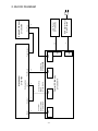
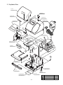
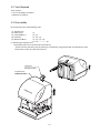
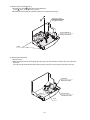
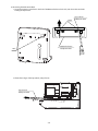
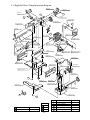
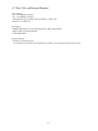
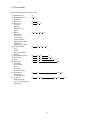
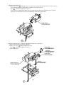
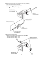
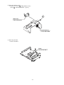
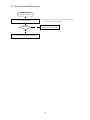
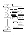
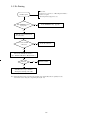
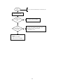
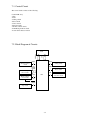
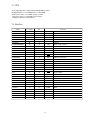
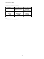
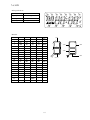
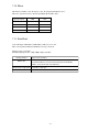
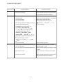
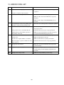
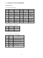
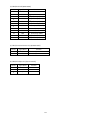
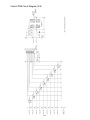
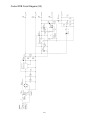
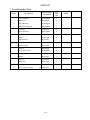
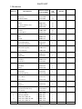
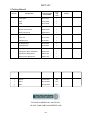
ELECTRONIC TIME RECORDER
TO PLACE AN ORDER CALL: 866-487-4751
OR VISIT: WWW.TIMECLOCKEXPERTS.COM
06-0297-000 Rev. B
5640 Departure Drive
Raleigh, NC 27616
Service Manual
CONTENTS
1. OUTLINE........................................................................................................ 1- 1
2. BLOCK DIAGRAM........................................................................................ 2- 1
3. DISASSEMBLY AND REASSEMBLY OF BASIC PARTS........................
3- 1. Exploded View........................................................................................
3- 2. Tools Required........................................................................................
3- 3. Disassembly.............................................................................................
3- 4. Reassembly..............................................................................................
33333-
1
2
3
3
7
4. DISASSEMBLY AND REASSEMBLY OF MECHANISM.........................
4- 1. Exploded View, Oiling Instruction Diagram...........................................
4- 2. Tools, Oils and Detergent Required........................................................
4- 3. Disassembly.............................................................................................
4- 4. Reassembly..............................................................................................
4- 1
4- 2
4- 3
4- 4
4-12
5. TROUBLESHOOTING...................................................................................
5- 1. No Operation............................................................................................
5- 2. No Display on the LCD Panel.................................................................
5- 3. Setting Switch Malfunctioning................................................................
5- 4. Motor Operation Failure..........................................................................
5- 5. No Printing...............................................................................................
5- 6. How to locate Problems from the Error Codes........................................
5555555-
1
2
3
4
5
6
7
6. MEASUREMENT...........................................................................................
6- 1. Voltage Check.........................................................................................
6- 2. Motor Operation Check...........................................................................
6- 3. Print Head Resistance Measurement.......................................................
6666-
1
2
2
3
7. CONTROL CIRCUIT OPERATION..............................................................
7- 1. Control Circuit........................................................................................
7- 2. Block Diagram of Circuits.....................................................................
7- 3. CPU........................................................................................................
7- 4. Port List..................................................................................................
7- 5. Operation Mode......................................................................................
7- 6. LCD........................................................................................................
7- 7. Switch.....................................................................................................
7- 8. Sensor.....................................................................................................
7- 9. Encoder...................................................................................................
7-10. Motor......................................................................................................
7-11. Print Head...............................................................................................
7- 1
7- 2
7- 2
7- 3
7- 3
7- 4
7- 5
7- 6
7- 6
7- 6
7-7
7- 7
8. POWER SUPPLY CIRCUIT........................................................................... 8- 1
9. INSPECTION SHEET..................................................................................... 9- 1
10. ERROR CODE LIST....................................................................................... 10- 1
11. CONNECTOR PIN ASSIGNMENT............................................................... 11- 1
12. CIRCUIT DIAGRAM...................................................................................... 12- 1
13. PARTS LIST.................................................................................................... 13- 1
1. OUTLINE
Be careful to avoid electric shock when repairing this unit.
<Cover off>
<Front view>
Cover
Ink Ribbon Ass'y
Key hole
Display
Display
Setting switch
Key Top
Print Head
<Print position adjuster>
The print position from the card
edge is adjustable by pressing
and sliding the print position
button located on the bottom .
<Back view>
Wall-mount holes
AC Adapter Ass'y
30mm
JAN31A
15mm
JAN 31AM12:00
JAN 31AM12:00
1-1
4
Encoder
Connector
Harness Ass'y
Q7000-5163A
2
CN5
Motor
2-1
Q7150-5001A
Control PCB Ass'y
CN3
Sensor Harness
B Unit
Q7150-5165U
8
4
sensor
CN4
Q7000-8000
Print Head
12
Print Head
CN2
CN6
CN1
2
Paper Sensor
2
20
Q7152-5210A
AC Adapter Ass'y
LCD Panel
3
Q7150-5505
Key Top
Q7150-5007A
Q7150-4000
Home position
Switch PCB Ass'y
Mechanism
2. BLOCK DIAGRAM
3. DISASSEMBLY AND REASSEMBLY OF
BASIC PARTS
CONTENTS
3-1. Exploded View .................................................................. 3-2
3-2. Tools Required .................................................................. 3-3
3-3. Disassembly ....................................................................... 3-3
3-4. Reassembly ........................................................................ 3-7
3-1
3-1. Exploded View
Cover B
P/N Q7152-2184
Lock Lever
P/N Q7152-2084
Indicator Plate
P/N Q7152-2010
Top Enclosure
P/N Q7152-2001
AC Adapter Ass'y
P/N Q7152-5210A
Selection Label
P/NQ7152-2042
k
k
Mechanism Block
i
i
Control PCB Ass'y
P/N Q7150-5001A
Printer Cover
P/N Q7152-2002
LCD Panel
P/N Q7150-5505
k
h
i
h
m
h
Paper Rack
P/N Q7152-2070
Bottom Enclosure
P/N Q7152-2003
Key Top
P/N Q7152-2510
PL Label
P/N Q0070-2646
UL,CSA,FCC Label
P/N Q0106-8665-1
Rubber
P/N Q7150-2065
Ref No.
3-2
General-use parts
Part No.
k
P.H.T. Screw (BT) 3x8
84001-3026
m
P.H. Screw M4x10, SPW
84001-4019
3-2. Tools Required
Tools required :
1. No. 2 or #2 Phillips screwdriver
2. Miniature screwdriver
3-3. Disassembly
Disassemble the parts in the following order :
(1)
(2)
(3)
(4)
(5)
Top Enclosure
Printer Cover
Control PCB Ass'y
LCD Panel
Mechanism Block
(1)
(1)—(2)
(1)—(2)—(3)
(1)—(2)—(3)—(4)
(1)—(2)—————–(5)
(1) Removing the Top Enclosure
1. Unlock the Lock Lever and remove the Top Enclosure.
*If the Lock Lever cannot be used, the unit may be unlocked by using tweezer with rounded points to push
the two holes on the rear of the Top Enclosure.
Lock Lever
P/N Q7152-2084
Top Enclosure
P/N Q7152-2001
3-3
(2) Removing the Printer Cover
1. Remove the AC Adapter Ass'y cord.
2. Remove two screws k holding the Printer Cover.
[Screw k : P.H.T. Screw (BT) 3x8 : 2 pieces]
k
Printer Cover
P/N Q7152-2002
AC Adapter Ass'y
P/N Q7152-5210A
2. Lift the Printer Cover up and turn to the same direction as the illustration (about 90°).
3. Remove harness from the connector of Control PCB Ass'y.
p
q
Control PCB Ass'y
P/N Q7150-5001A
Printer Cover
P/N Q7152-2002
h
i
n
3-4
Connector No.
Numbers of Wire
n
CN1
20
Part No.
h
CN2
3
Q7150-5007A
i
CN3
8
Q7150-5165U
p
CN4
12
q
CN5
2
Q7150-5505
Q7000-8000
Q7000-5163A
(3) Removing the Control PCB Ass'y
1. Remove two screws k holding the Control PCB Ass'y.
[Screw k : P.H.T. Screw (BT) 3x8 : 2 pieces]
2. Remove the Control PCB Ass'y from the Printer Cover hooks by rotating it.
Printer Cover
P/N Q7152-2002
k
Control PCB Ass'y
P/N Q7150-5001A
Hook
(4) Removing the LCD Panel
1. Remove a tape.
2. After releasing the two hooks holding the LCD Panel, push the LCD from the other side, and remove the
LCD Panel.
*Since the hooks that hold the LCD Panel break easily, please do not push any harder than necessary.
LCD Panel
P/N Q7150-5505
Hook
Printer Cover
P/N Q7152-2002
Tape
3-5
(5) Removing the Mechanism Block
1. Insert the miniature screwdriver in the hole of the Bottom Enclosure back side, and release the two hooks
holding the Paper Rack .
Hook
Bottom Enclosure
P/N Q7152-2003
Hole
2. Lift the front edges of the Paper Rack, and pull it out.
Paper Rack
P/N Q7152-2070
3-6
Paper Rack
P/N Q7152-2070
3. Remove the Key Top.
4. Release harness connecting with Switch PCB Ass'y from the hook.
5. Open the hook and release fixing of Switch PCB Ass'y.
Hook
Switch PCB Ass'y
P/N Q7150-5007A
Key Top
P/N Q7152-2510
Hook
6. Remove two screws m holding the Mechanism Block.
[Screw m : P.H. Screw M4x10 , SPW : 2 pieces]
7. Remove the Mechanism Block by rotating it in the same direction as the illustration.
Mechanism Block
m
3- 4. Reassembly
Reassembly of parts is performed by reversing the disassembly procedure.
Note the following points :
(1) Make sure that all connectors and screws are properly secured in place.
(2) Take care to avoid catching or cutting the harnesses or cables when mounting parts.
(3) Once reassembled, check all functions to ascertain that the reassembly procedure has been properly completed.
3-7
4. DISASSEMBLY AND REASSEMBLY OF
MECHANISM
CONTENTS
4-1. Exploded View, Oiling Instruction Diagram ............................... 4- 2
4-2. Tools, Oils and Detergent Required ............................................. 4- 3
4-3. Disassembly ................................................................................. 4- 4
4-4. Reassembly ................................................................................... 4-12
4-1
4-1. Exploded View, Oiling Instruction Diagram
Mid Gear
P/N Q0100-1137
Motor Ass'y
P/N Q7150-1014A
i
Cam Gear
P/N Q0100-1554-1
c
b
c
Bearing
P/N Q0100-1035
Carrier Sub Plate
P/N Q7000-1466
Platen Gear
P/N Q7150-1082
Base Plate Ass'y
P/N Q7150-1040A
d
i
Bearing
P/N Q0100-1035
r
Guide Shaft
P/N Q7150-1051
g
c
Clutch Gear
P/N Q7000-1548
Carrier Spring
P/N Q7000-1166-1
Cam B
P/N Q0100-3275
Ink Ribbon Ass'y
P/N Q7014-1310A
Cam
P/N Q0100-1576
Head Holding Plate
P/N Q7000-1729
Carrier Ass'y
P/N Q7150-1160A
Lead Screw Shaft
P/N Q7000-1327
Tractor Shaft Spring
P/N 84950-1586
e Blade part of Cam
and Cam B
Sheet
P/N Q7150-1842-1
Spacer
P/N Q7150-1387
f Shank of
Cam B
Ribbon Driving Wheel
P/N Q7000-1673
Print Head
P/N Q7000-8000
Platen Ass'y
P/N Q7150-1060A
Reinforcing Plate
P/N Q7150-1054
Ribbon Driving Shaft
P/N Q7000-1674-1
Sensor Lever
P/N Q7150-1886
Reinforcing Plate
P/N Q7150-1054
Sensor Block
P/N Q7150-1885
Cam C
P/N Q7150-3276
e
h
Paper Pressure Plate Ass'y
P/N Q7150-1067A
Platen Gear B
P/N Q7150-1551
c
Stopper A
P/N Q7150-1234
e
f
Platen Plate Spring
P/N Q7150-1630
Bottom Plate
P/N Q7150-1694
h
Platen Plate
P/N Q7150-1629
f
Cam Shaft
P/N Q7150-1527
Platen Cover
P/N Q7150-1648
c
Ref No.
Lubricant
General-use parts
Part No.
a
Tielap TY-23M
84009-1060
b
P.H. Screw M2.6x5
84001-2641
e
YM-103
c
P.H.T. Screw(BT) 3x6
84001-3025
h
Switch PCB Ass'y
P/N Q7150-5007A
f
SFP-13
d
P.H.T. Screw(BT) 3x6, PW
84001-3250
i
Sensor Harness B Unit
P/N Q7150-5165U
g
N-4K
r
P.H.T. Screw(BT) 3x8
84001-3026
4-2
4-2. Tools, Oils, and Detergent Required
Tools required :
1. No. 2 or #2 Phillips screwdriver
2. No. 1 or #1 Phillips screwdriver
3. Standard blade type screwdriver with a tip thickness of 1mm or less
4. Tweezers (for small parts)
Oils required :
1. YM-103 (The blade part of Cam and Cam B, Cam C, Shaft of Platen Plate )
2. SFP-13 (Shaft of Cam B, Cam Shaft)
3. N-4K (Guide Shaft)
Detergent required :
1. Alcohol (for cleaning the parts)
*To clean the parts, moisten a soft cloth with alcohol and wipe. Do not dip the parts directly into alcohol.
4-3
4-3. Disassembly
Disassemble the parts in the following order :
(1) Ink Ribbon Ass'y
(2) Head Holding Plate
Print Head
(3) Platen Cover
(4) Platen Gear
Cam Gear
Mid Gear
Base Plate Ass'y
Spacer
(5) Bearing
Guide Shaft
Carrier Ass'y
Carrier Spring
Carrier Sub Plate
Ribbon Driving Wheel
Clutch Gear
Ribbon Driving Shaft
(6) Lead Screw Shaft
Cam
Cam B
Tractor Shaft Spring
Bearing
(7) Sensor Harness B Unit
(8) Motor Ass'y
(9) Sheet
(10) Platen Ass'y
Cam Shaft
Platen Gear B
Cam C
Platen Plate
Platen Plate Spring
(11) Sensor Block
Sensor Lever
Switch PCB Ass'y
(12) Stopper A
Reinforcing Plate
Paper Pressure Plate Ass'y
Bottom Plate
(1)
(1) (2)
(1)
(1)
(3)
(3) (4)
(1) (2) (3) (4) (5)
(1)
(3) (4) (5) (6)
(1)
(1)
(1)
(1)
(3) (4)
(3) (4)
(3) (4)
(3)
(1)
(3)
(1)
(3) (4)
(7)
(7) (8)
(9)
(10)
(10) (11)
(9) (10)
4-4
(12)
(1) Removing the Ink Ribbon Ass'y
1. Hold the handle of the Ink Ribbon Ass'y and remove it by pulling sideways.
Ink Ribbon Ass'y
P/N Q7014-1310A
Handle
(2) Removing the Head Holding Plate and Print Head
1. Put the Head Holding Plate in the direction of arrow A with a screwdriver or tweezers and remove it.
2. Pull up the Print Head and remove it in the horizontal direction as shown by arrow B.
Head Holding Plate
P/N Q7000-1729
B
A
Print Head
P/N Q7000-8000
4-5
(3) Removing the Platen Cover
1. Remove two screws c holding the Platen Cover and move the Sensor Block in the direction shown by arrow A
so as to slide the Platen Cover in the direction shown by arrow B for removal.
[Screw c : P.H.T. Screw (BT) 3x6 : 2 pieces]
*Carry out the procedure with the Platen Ass'y pressed downward. (Rotate the Cam Shaft to press down the
Platen Ass'y. As the Platen Ass'y moves just underneath, it will emit a click sound.)
A
B
Platen Cover
P/N Q7150-1648
c
(4) Removing the Platen Gear, Cam Gear, Mid Gear, Base Plate Ass'y, and Spacer.
1. Remove the Platen Gear, Cam Gear, Mid Gear.
2. Remove two screws c holding the Base Plate Ass'y.
[Screw c : P.H.T. Screw (BT) 3x6 : 2 pieces]
3. Remove the Spacer.
Cam Gear
P/N Q0100-1554-1
Mid Gear
P/N Q0100-1137
Platen Gear
P/N Q7150-1082
Spacer
P/N Q7150-1387
Base Plate Ass'y
P/N Q7150-1040A
c
4-6
(5) Removing the Bearing (this side), Guide Shaft, Carrier Ass'y, Carrier Spring,
Carrier Sub Plate, Ribbon Driving Wheel, Clutch Gear, and Ribbon Driving Shaft.
1. Remove one screw c holding the Bearing (this side).
[Screw c : P.H.T. Screw (BT) 3x6 : 1 piece]
2. Remove the Guide Shaft from the Base Plate Ass'y.
3. Remove the Carrier Ass'y from the Base Plate Ass'y.
4. Remove the Carrier Spring from the Carrier Ass'y.
5. Remove one screw d holding the Carrier Sub Plate.
[Screw d : P.H.T. Screw (BT) 3x6, PW : 1 piece]
6. Remove the Ribbon Driving Wheel, Clutch Gear, and Ribbon Driving Shaft.
Base Plate Ass'y
P/N Q7150-1040A
Carrier Sub Plate
P/N Q7000-1466
Bearing
P/N Q0100-1035
d
Carrier Spring
P/N Q7000-1166-1
c
Guide Shaft
P/N Q7150-1051
Carrier Ass'y
P/N Q7150-1160A
Clutch Gear
P/N Q7000-1548
Ribbon Driving Shaft
P/N Q7000-1674-1
Ribbon Driving Wheel
P/N Q7000-1673
4-7
(6) Removing the Lead Screw Shaft, Cam, Cam B, Tractor Shaft Spring, and Bearing
1. Pull out the Lead Screw Shaft from the Cam B
2. Remove the Cam, Cam B, and Tractor Shaft Spring.
3. Remove one screw c holding the Bearing.
[Screw c : P.H.T. Screw (BT) 3x6 : 1 piece]
c
Base Plate Ass'y
P/N Q7150-1040A
Bearing
P/N Q0100-1035
Lead Screw Shaft
P/N Q7000-1327
Cam
P/N Q0100-1576
Cam B
P/N Q0100-3275
Tractor Shaft Spring
P/N 84950-1586
(7) Removing the Sensor Harness B Unit
1. Remove one screw c and one screw r holding the Sensor Harness B Unit
[Screw c : P.H.T. Screw (BT) 3x6 : 1 piece]
[Screw r : P.H.T. Screw (BT) 3x8 : 1 piece]
c
Base Plate Ass'y
P/N Q7150-1040A
4-8
Sensor Harness B Unit
P/N Q7150-5165U
r
(8) Removing the Motor Ass'y
1. Remove two screws b holding the Motor Ass'y.
[Screw b : P.H. Screw M2.6x5 : 2 pieces]
b
Motor Ass'y
P/N Q7150-1014A
Base Plate Ass'y
P/N Q7150-1040A
(9) Removing the Sheet
1. Remove the Sheet.
Sheet
P/N Q7150-1842-1
4-9
(10) Removing the Platen Ass'y, Cam Shaft, Platen Gear B, Cam C, Platen Plate, and Platen Plate Spring
1. Remove the Platen Ass'y by releasing the hook of the Platen Plate.
*Do not peel off the tapes adhering the Platen Ass'y.
2. Pull out the Cam Shaft by pressing down the Platen Plate, and remove the Platen Gear B.
3. Remove the Cam C, Platen Plate, and Platen Plate Spring.
Platen Ass'y
P/N Q7150-1060A
Cam C
P/N Q7150-3276
Platen Plate
P/N Q7150-1629
Platen Gear B
P/N Q7150-1551
Platen Plate Spring
P/N Q7150-1630
Cam Shaft
P/N Q7150-1527
Platen Cover
P/N Q7150-1648
4-10
(11) Removing the Sensor Block, Sensor Lever, and Switch PCB Ass'y
1. Move the Sensor Block in the direction shown by arrow A and remove it from the Platen Cover while pulling it
upward.
2. Remove the Sensor Lever with tweezers
3. Release the hook part of the Sensor Block and remove the Switch PCB Ass'y.
Sensor Block
P/N Q7150-1885
Sensor Lever
P/N Q7150-1886
Platen Cover
P/N Q7150-1648
Switch PCB Ass'y
P/N Q7150-5007A
A
(12) Removing the Stopper A, Reinforcing Plate, Paper Pressure Plate Ass'y, and Bottom Plate
1. Remove the Stopper A with tweezers.
2. Do not disassemble the Reinforcing Plate, Paper Pressure Plate Ass'y and Bottom Plate unless its removal is
necessary.
*Do not peel off the tapes adhering the Paper Pressure Plate Ass'y.
Paper Pressure Plate Ass'y
P/N Q7150-1067A
Reinforcing Plate
P/N Q7150-1054
Reinforcing Plate
P/N Q7150-1054
Stopper A
P/N Q7150-1234
Bottom Plate
P/N Q7150-1694
4-11
4- 4. Reassembly
Reassembly of parts is performed by reversing the disassembly procedure.
Note the following points :
(1) Properly lubricate all parts that require lubrication.
(2) Bundle harnesses firmly and accurately enough to avoid interference with gears
(3) Lastly install the Platen Gear B as follows (See the drawing):
• Match the Cam Gear and the hole of the Base Plate Ass'y.
• Place the hole of the Platen Gear B facing straight upward. As it comes into the upright position, it will emit a
clicking sound. At this time, the Platen Ass'y is at the lowered position.
(4) Check the following sliding parts :
1. Gears
2. Cam and Cam B
3. Carrier Ass'y
4. Platen Cover and Sensor Block
5. Sensor Block and Sensor Lever
6. Platen Block
Hole
(5) Check clearances in the following parts :
1. Cam and Cam B (right and left)
2. Carrier Ass'y (rack engagement)
3. Platen Plate
(6) Check for backlash between gears.
(7) Attach spring parts firmly at their right places to ensure the spring works properly.
*Attach the Carrier Spring so that their faces contact the Guide Shaft.
(8) Attach two sensors of the Sensor Harness B Unit firmly at their right places
*The one with a longer harness is the home position sensor, while the one with a shorter
harness is the encoder sensor.
(9) When attaching hook-shaped parts, be sure that the hook parts are firmly attached.
(10) Direct the Cam C in the proper direction when installing it.
(11) When installing the FPC of the Print Head on the Base Plate Ass'y, check to see if the installation length of the
FPC is appropriate or not by moving the Carrier laterally.
(12) When assembling the harness of Switch PCB Ass'y to the Platen Cover, be sure that the Sensor Block operates
to the proper range.
4-12
5. TROUBLESHOOTING
CONTENTS
5-1. No Operation................................................................................... 5-2
5-2. No Display on the LCD Panel......................................................... 5-3
5-3. Setting Switch Malfunctioning........................................................ 5-4
5-4. Motor Operation Failure.................................................................. 5-5
5-5. No Printing ..................................................................................... 5-6
5-6. How to locate Problems from the Error Codes............................... 5-7
5-1
5-1. No Operation
• Digits are not displayed on the LCD.
• Unable to print.
No operation
Check the AC Adapter Ass'y output voltage level.
(See "Voltage Check.")
Normal?
AC Adapter Ass'y failure.
No
Yes
Turn the power off and detach
the outer jacket.
Check the 5V and 10V voltage levels.
(See "Voltage Check.")
No
Is fuse F1 blown?
Yes
Normal?
No
Determine the cause of the blown fuse.
• Foreign matter (metal, etc.)
• Caught or exposed wires
• Short circuit caused by inadequate soldering
Change the fuse.
For safty reasons,
replace only with the same type and rating of Fuse.
Yes
• Regulator IC P3 failure
• Short circuit
• Over load
No
Is the 10V level
being output?
Yes
• Regulator IC P4 failure
• Short circuit
• Over load
No
Is the 5V level
being output?
Yes
Control circuit failure.
5-2
5-2. No Display on the LCD Panel
Nothing is displayed
on the LCD Panel.
• Nothing appears on the screen.
• There is only a partial display on the screen, or the screen flickers.
Note: Pressing the reset switch causes the settings, including the time
and calendar settings, to be initialized.
Perform the function test to check the LCD Panel.
See "Inspection Sheet"
How is the
display?
Nothing is displayed.
Partial display or the screen is flickering.
Is connector CN1
connected?
Yes
• Inadequate CPU soldering
• Inadequate LCD heat seal
See "1. No Operation."
5-3
No
Secure the connector.
5-3. Setting Switch Malfunctioning
Unable to input
with the setting switches.
Perform the function test to check key switches.
See "Inspection Sheet"
Normal?
No
Note: Pressing the reset switch causes the settings, including the time
and calendar settings, to be initialized.
• Key switch failure
• Inadequate soldering on CPU
Yes
There are no anomalies in the setting switch.
5-4
5-4. Motor Operation Failure
• Motor does not run at all.
• Motor runs abnormally.
Motor does not run.
Plug the AC Adapter Ass'y into the outlet.
Press the reset switch.
Note: Pressing the reset switch causes the settings, including the time
and calendar settings, to be initialized.
Turn the power off and detach
the outer jacket.
No
Carrier cycles once?
Yes
Secure the connector.
Turn the power off and detach
the outer jacket.
Is connector CN5
connected?
No
Yes
Is connector CN2
connected?
No
Yes
Insert the time card for punching.
Secure the connector.
• Regulator IC P3 failure
• Short circuit
• Over load
Check the 10V voltage levels.
(See "Voltage Check.")
No
Normal?
Yes
Check the Motor operation.
(See "Motor Operation Check.")
Motor failure.
No
Normal?
Yes
• Motor driver IC P2 failure
• Inadequate soldering on the CPU
Does the Motor
operate?
Motor does not run.
• Card detection switch failure
• Inadequate harness soldering
on the Switch PCB Ass'y or Card detection switch
• Inadequate soldering on the CPU
An error message appears.
See "6. How to locate Problems from
the Error Codes."
5-5
5-5. No Printing
• Motor runs.
If the motor does not run, see "4 Motor Operation Failure."
• Card does not print.
• Abnormal printout (chipped dots, etc.)
Unable to print
Is the Ink Ribbon Ass'y
set properly ?
No
Set the Ink Ribbon Ass'y properly.
Yes
Turn the power off and detach
the outer jacket.
Is connector CN4
connected?
No
Secure the connector.
Yes
Measure the Print Head resistance.
(See "Print Head Resistance Measurement.")
Normal?
No
Print Head failure
Yes
• Print Head driver Q2 - 10 failure
• Inadequate soldering on the CPU
Note: If the Print Head resistance is less than the prescribed value, the Print Head driver is probably defective.
You will also need to change the corresponding drivers (Q2 - 10).
5-6
5-6. How to locate Problems from the Error Codes
• Built-in memory is not retained during power failure.
• Anomaly of built-in memory data
E-01
Press reset switch,
disconnect the power for 2 to 3 minutes,
and then turn on the power.
Is "E-01" displayed?
No
Note: Pressing the reset switch causes the settings, including the time
and calendar settings, to be initialized.
Causes:
CPU out of control due to AC line noise
or static electricity.
Yes
Causes:
1) Lithium Battery voltage drop
2) Inadequate solder jumper on the JP1
3) Power failure detection circuit failure
E-30
Is there
any anomaly
in the CR-system
Mechanism?
Note: When Lithium Battery voltage is 2V or less, replace battery.
(Battery life is 5 years in accumulated power failure time.)
When replacing Lithium Battery, make sure solder jumper is done
for the JP1 and press the reset switch.
• Print Head fails to return to its home position.
No
Causes:
1) Home position sensor failure
2) Home position sensor circuit failure
3) CR-system Mechanism failure
Yes
Eliminate causes.
5-7
E-38
• There are anomalies in the CR motor or the CR encoder.
Insert the time card.
Does
the CR motor
run?
No
See "4. Motor Operation Failure."
No
Eliminate causes.
• Are there any anomalies in the CR-system
Mechanism, such as Cam, Carrier
or Ink Ribbon Ass'y?
Yes
Does
the Carrier Ass'y move
smoothly?
Yes
Causes:
1) CR encoder failure
2) CR encoder circuit failure
5-8
6. MEASUREMENT
CONTENTS
6-1. Voltage Check ..................................................................... 6-2
6-2. Motor Operation Check ....................................................... 6-2
6-3. Print Head Resistance Measurement ................................... 6-3
6-1
6-1. Voltage Check
• AC Adapter Ass'y
Measure the voltage at the AC Adapter Ass'y plug.
Measuring point
Outside metal
Target voltage
Inside metal
17.6VAC ± 15%
Measuring conditions
AC Adapter Ass'y plugged in.
• Control PCB Ass'y
Use test pin land TP2, 3, and 5 to measure voltage.
Measuring point
Target voltage
Measuring conditions
10V (TP2)
GND (TP5)
10.85VDC ± 6%
AC Adapter Ass'y plugged in.
5V (TP3)
GND (TP5)
5VDC ± 5%
AC Adapter Ass'y plugged in.
6-2. Motor Operation Check
Apply voltage as follows to the harness inserted to the connector CN5 and check whether the Motor runs properly.
Motor
Movement
CR motor
Print Head is fore-and-aft and Platen Ass'y is up-and-down.
6-2
Voltage applied
Pin 1 (red)
Pin 2 (green)
GND
9VDC
6-3. Print Head Resistance Measurement
Measure the Print Head resistance at the terminals with the FPC harness inserted to the CN4.
Measuring point
1
8
2
8
3
8
4
8
5
8
6
8
7
8
9
8
10
8
11
8
12
8
Target resistance
Open
2.35 ± 0.2
2.35 ± 0.2
2.35 ± 0.2
2.35 ± 0.2
2.35 ± 0.2
Short
2.35 ± 0.2
2.35 ± 0.2
2.35 ± 0.2
2.35 ± 0.2
Note: If the Print Head resistance is smaller than
the value shown on the left, there is a
possibility that the Print Head pin driver
is broken. In that case, replace Print Head
and check drivers Q2 - 10.
1
12
6-3
8, 7
7. CONTROL CIRCUIT OPERATION
CONTENTS
77777777-
1. Control Circuit ................................................................. 72. Block Diagram of Circuits ............................................... 73. CPU ................................................................................. 74. Port List ........................................................................... 75. Operation Mode .............................................................. 76. LCD ................................................................................. 77. Switch............................................................................... 78. Sensor .............................................................................. 7-
2
2
3
3
4
5
6
6
7- 9. Encoder ............................................................................ 7- 6
7-10. Motor ............................................................................... 7- 7
7-11. Print Head ........................................................................ 7- 7
7-1
7-1. Control Circuit
The control circuit consists of the following:
Control PCB Ass'y
• CPU
• LCD
• Setting switch
• Reset switch
• Sensor circuit
• Encoder circuit
• CR motor driver circuit
• Print Head pin driver circuit
• Power failure detector circuit
7-2. Block Diagram of Circuits
CR motor driver
circuit
Print Head pin
driver circuit
16
S0-15
4
COM0-3
LCD
P30,31
P60,62
2
3
P20
P80-83
P90-93
RESET
1
9
P10,12
2
CR encoder/
Home position
sensor circuit
P00
CPU
1
P53
1
Paper Sensor/ Key
Top circuit
P01,02
2
7-2
Setting switch
Reset switch
Power failure
detection circuit
7-3. CPU
• 4-bit single-chip microcomputer µPD753108GC(NEC product)
• Equipped with 8,192 x 8 bit ROM and 512 x 4bit RAM
• Main system clock is a 4.19 MHz ceramic oscillator.
Subsystem clock is a 32.768 kHz crystal oscillator.
Equipped with LCD controller/driver.
7-4. Port List
Name
P00/INT4
P01/SCK
P02/SO/SB0
P03/SI/SB1
P10/INT0
P11/INT1
P12/INT2/TI1/TI2
P13/TI0
P20/PT00
P21/PT01
P22/PCL/PT02
P23/BUZ
P30/LCDCL
P31/SYNC
P32
P33
P50
P51
P52
P53
P60/KR0
P61/KR1
P62/KR2
P63/KR3
S23/P80
S22/P81
S21/P82
S20/P83
S19/P90
S18/P91
S17/P92
S16/P93
No. of Pins
25
26
27
28
29
30
31
32
33
34
35
36
5
6
7
8
10
11
12
13
14
15
16
17
37
38
39
40
41
42
43
44
I/O
I
I
I
I
I
I
I
I
O
O
O
O
O
O
O
O
O
O
O
O
I
I
I
I
O
O
O
O
O
O
O
O
PWF
PS
PB
ENC
SH
PIN9
BUZ
CR0
CR1
ESN
SEL
CHG
SET
PIN8
PIN7
PIN6
PIN5
PIN4
PIN3
PIN2
PIN1
7-3
Function
Power failure detection
Paper Sensor
Key Top
Unused
CR encoder
Unused
Home position sensor
Unused
Pin9
Unused
Unused
Clock trimming
CR motor control 0
CR motor control 1
Unused
Unused
Unused
Unused
Unused
Sensor enable
SELECT switch
CHANGE switch
SET switch
Unused
Pin8
Pin7
Pin6
Pin5
Pin4
Pin3
Pin2
Pin1
7-5. Operation Mode
Operation mode and functions are as follows:
A
B
Operation state
Normal operation
All functions operation
Power failure operation
Time update
Memory retention only
AC power
ON
OFF
CPU state
(clock)
Operation mode
(4.19 MHz)
Halt mode
(32.768 kHz)
PWF (P00)
H
L
When a power failure causes the output voltage of the 10V-regulator IC to drop below about 7V,
PWF(P00) is set to "L."
This allows the unit to enter into Mode B.
7-4
7-6. LCD
• LCD specifications
Operating voltage
Lighting method
Viewing direction
Operating method
5V
Reflective type
6:00
1/4 duty, 1/3 bias,128 Hz
T1
T2
T3
T4
T5
T6
T7
T8
M1
1
2
3
4
T9
A
M2
5
M3
6
F
B
G
E
M4
T10
C
D
T11
S1
S2
S3
S4
S5
• Pin table
Pin No.
1
2
3
4
5
6
7
8
9
10
11
12
13
14
15
16
17
18
19
20
COM1
T7
M1
AM
1D
PM
2D
S1
3D
S2
4D
S3
S4
5D
S5
6D
T11
COM1
-
COM2
T6
T1
1E
1C
2E
2C
3E
3C
4E
4C
M4
5E
5C
6E
6C
T10
COM2
-
COM3
T5
T2
1F
1G
2F
2G
3F
3G
4F
4G
M3
5F
5G
6F
6G
T9
C0M3
-
COM4
T4
T3
1A
1B
2A
2B
3A
3B
4A
4B
M2
5A
5B
6A
6B
T8
COM4
SEGn
SEG1
SEG2
SEG3
SEG4
SEG5
SEG6
SEG7
SEG8
SEG9
SEG10
SEG11
SEG12
SEG13
SEG14
SEG15
SEG16
-
7-5
A
F
B
COM3
COM4
G
C
E
COM2
D
S
COM1
SEGn +1
7-7. Switch
The switch state is input the port below.
Switch state: L ...... ON, H ...... OFF
PS(P01): Paper Sensor
Detects presence of a card.
Normally "off". When a card is put in, it pushed a sensor lever, it turn a sensor to "on".
PB(P02): Key Top
For manual printing.
Normally "off". When the Key Top is pressed, it turn a switch to "on".
SEL(P60/KR0): SELECT switch
Setting switch.
Normally "off". When a switch is pressed, it turn a switch to "on".
CHG(P61/KR1): CHANGE switch
Setting switch.
Normally "off". When a switch is pressed, it turn a switch to "on".
SET(P62/KR2): SET switch
Setting switch.
Normally "off". When a switch is pressed, it turn a switch to "on".
7-8. Sensor
Set ESN(P53) to "L" to allow the sensor infrared LED to glow and make the sensor state readable.
Sensor state: L ...... light-passing, H ...... shading.
SH(P12/INT2) : Home position sensor
Detects the home position of the Print Head.
7-9. Encoder
Set ESN(P53) to "L" to allow the sensor infrared LED to glow and make the encoder state readable.
Encoder state: L ...... light-passing, H ...... shading.
ENC(P10/INT0) : CR encoder
Detects the revolution of CR motor.
7-6
7-10. Motor
The CR motor CCW to cause the Cam to rotate, allowing the Print Head to move.
The motor operation mode is controlled by CR0 (P30) and CR 1 (P31).
Operation mode
CR0
CR1
Stand-by
L
L
CW
H
L
CCW
L
H
Brake
H
H
7-11. Print Head
A pin will impact when PIN1-9 (P20, P80-83, P90-93) is set to "H".
The record is printed when the Print Head is moving to the front.
Driving voltage: 9.5V±10%
Print Head pin impact time: 380µs, 400µs, 420µs (Variable)
Printing method
Ribbon life
Impact serial dot matrix
Violet, over 0.51 million characters or 1 year:
provided the ribbon is used at normal temperature and humidity
within 1 year from the date of manufacture.
Character dot composition 9 dots (H) x 7 dots (W)
Print Head life
Over 2.8 million characters
7-7
8. POWER SUPPLY CIRCUIT
(on Control PCB Ass'y)
1. 14-19Vac is provided from AC Adapter Ass'y to the connector CN6.
2. 14-19Vac is provided to DB1 after removing noise due to FB1 and FB2. And being rectified by DB1 and smoothed
by C16 and C17 and is provided to regulator P3 that regulates into 10Vdc.
3. 10Vdc drives the pins and the motor.
4. And 10Vdc is regulated to 5Vdc by regulator P4. 5Vdc is supplied to the control circuit.
8-1
9. INSPECTION SHEET
Inspection Item
Turn On
Inspection Method
Inspection Standard
• Insert the AC Adapter Ass'y to the AC power outlet.
• Make sure initial operation was made and the
• Press the reset switch.
display indicates the time at 12:00 a.m.
LCD Check
• Display shows " 710-**".
• Press the SELECT and reset switch
Make sure readouts other than ** are identical.
simultaneously.
• Press the SET switch.
• Make sure the entire LCD is lit up.
• Press the SET switch.
• Make sure the entire LCD is put out.
• Each pressing of the SET switch causes the LC
• " "(16 pieces), " ' ","AM","PM"," : ", "– " are
lit up in sequence.
to glow in this following order.
PASSWORD
none
D.S.T.START
PRINT DIRECTION
none
none
LANGUAGE
LEADING ZERO
YEAR DIGIT
DATE
D.S.T.END
HOUR MIN.
PRINT ORDER
TIME
COMMENT
'
AM
HOUR
PM
:
–
• Repeated pressing of the SET switch causes
the display to change as follows.
000000
111111
222222
...........
88
8888
9999
99
Printing Check
• Press the SET switch.
• Make sure initial operation.
• Set the knob on the bottom to the center and
• Make sure the printed output is as follows.
Example) JAN 1 AM12:00
print out three times.
• Press the SET and reset switch simultaneously.
• Make sure initial operation, and display shows
"000000".
• Make sure twenty "E" characters are printed
• Print out three times.
out.
• Make sure initial operation was made and the
• Press the reset switch.
display indicates the time at 12:00 a.m.
9-1
Inspection Item
CHANGE
Switch Check
Inspection Method
Inspection Standard
• Press the SELECT switch and move
position TIME.
• Press the CHANGE switch when 6:00 is shown. • Make sure a readout on seconds advances.
** 6:00 - ** gives a readout on seconds.
• Press the SET switch twice.
• Press the SELECT switch and move
position
PRINT DIRECTION/PRINT ACTIVATION.
• Pressing the SET switch makes CC (Print
Activation) flicker.
• Press the CHANGE switch when "3:Manual" is
shown.
Manual Print
Check
• Press the SET switch twice.
• Make sure the time displays and ":" flickers.
• Pull the knob on the bottom toward yourself
• No printed output is produced when the card is
and insert the card.
inserted.
• Press the Key Top and print out three times.
• Make sure the printed output is as follows.
Example) JAN 1 AM 6:00
• Make sure the starting point of printed output is
within 1 mm from the edge of a card.
Lithium
• Check the time.
Battery Check
• Pull out the AC Adapter Ass'y.
• Make sure entire LCD is put out.
• Leave one minutes.
• Insert the AC Adapter Ass'y to the AC power
outlet.
Completion of
• Press the reset switch.
Check
• Pull out the AC Adapter Ass'y.
• Make sure the time display did not return to
"AM12:00".
9-2
10. ERROR CODE LIST
No
E-00
Error Symptoms
Remedies
CPU does not function properly.
1. Press the reset switch and check the CPU for proper
operation.
Program is corrupted or CPU is broken.
E-01
Memory retention is not possible.
1. Make sure the Lithium Battery is properly installed.
2. Make sure JP2 of the Control PCB Ass'y is properly
installed.
3. Make sure the voltage of the Lithium Battery is not
lowered.
E-05
No-card detection occurs before printing in the
1. Press the card on the Paper Sensor until time is printed.
automatic or semi-automatic printing modes.
E-30
Print Head does not return to the home position.
1. Make sure the home position sensor is installed in
the proper position.
Home position sensor is not shaded after the
2. Check the CR encoder sensor for proper function.
Print Head home position initial operation or
3. Make sure gears in the CR motor system are properly
after printing of the card.
E-38
engaged and the Print Head properly moves.
There is an anomaly in the CR motor or CR
1. Check the CR encoder sensor for proper operation.
encoder sensor.
2. Make sure the CR motor can run.
Encoder does not pulse within 1 sec. after the
3. Make sure the CR motor system gears meshed.
CR motor begins to operate or within 15.3 msec.
4. Check the CR encoder sensor for proper placement.
during operation.
E-40
Wrong password is entered.
1. Enter the correct password that has been input in the
password setting.
E-41
Daylight saving time setting is incorrect.
1. Change the setting being care not to input the same
month and day for when daylight saving time starts
and ends.
E-49
An impractical setting is made.
1. Make the setting within the practical range.
10-1
11. CONNECTOR PIN ASSIGNMENT
Control PCB Ass'y
(1) CN1 (LCD Panel (Q7150-5505))
Pin No.
Signal Name
1
COM 4
2
Function
Pin No.
Signal Name
Function
COMMON4
11
SEG10
SEGMENT10
COM 3
COMMON3
12
SEG9
SEGMENT9
3
COM 2
COMMON2
13
SEG8
SEGMENT8
4
COM 1
COMMON1
14
SEG7
SEGMENT7
5
SEG16
SEGMENT16
15
SEG6
SEGMENT6
6
SEG15
SEGMENT15
16
SEG5
SEGMENT5
7
SEG14
SEGMENT14
17
SEG4
SEGMENT4
8
SEG13
SEGMENT13
18
SEG3
SEGMENT3
9
SEG12
SEGMENT12
19
SEG2
SEGMENT2
10
SEG11
SEGMENT11
20
SEG1
SEGMENT1
(2) CN2 (Switch PCB Ass'y (Q7150-5007A))
Pin No.
Signal Name
1
PB
2
GND
3
PS
Function
Key Top
Paper Sensor
(3) CN3 (Sensor Harness B Unit (Q7150-5165U))
Pin No.
Signal Name
Function
1
SHC
Home position sensor collector (SH)
2
SHE
Home position sensor emitter
3
SHA
Home position sensor anode
4
SHK
Home position sensor cathode
5
ENC
CR encoder collector (ENC)
6
ENE
CR encoder emitter
7
ENA
CR encoder anode
8
ENK
CR encoder cathode
11-1
(4) CN4 (Print Head (Q7000-8000))
Pin No.
Signal Name
1
FG
2
PIN6
frame
3
PIN4
6th pin from top (PIN6)
4
PIN8
4th pin from top (PIN4)
5
PIN2
8th pin from top (PIN8)
6
PIN9
2nd pin from top (PIN2)
7
COM
Bottom pin (PIN9)
8
COM
Common (10V)
9
PIN7
Common (10V)
10
PIN1
7th pin from top (PIN7)
11
PIN5
Top pin (PIN1)
12
PIN3
5th pin from top (PIN5)
Function
Connection to head
(5) CN5 (Connector Harness Ass'y (Q7000-5163A))
Pin No.
Signal Name
Function
1
CRA
CR motor (+)
2
CRB
CR motor (-)
(6) CN6 (AC Adapter Ass'y (Q7152-5210A))
Pin No.
Signal Name
1
AC
2
AC
3
-
Function
11-2
12. CIRCUIT DIAGRAM
Control PCB Circuit Diagram (1/3)
12-1
Control PCB Circuit Diagram (2/3)
12-2
BL02RN2-R62
(muRata)
BL02RN2-R62
(muRata)
Control PCB Circuit Diagram (3/3)
12-3
Switch PCB Circuit Diagram
12-4
13. PARTS LIST
CONTENTS
13-1. Overall Exploded View ............................................................... 13-2
13-2. Mechanism ................................................................................... 13-3
13-3. Control PCB Ass'y....................................................................... 13-4
13-4. Packing Material ......................................................................... 13-5
13-5. Lubricant ..................................................................................... 13-5
Note 1 : The ordering unit of part with the mark "#" is 10 pieces or sets.
(e.g. 10,20,30,---)
Note 2 : ( ) in 3' TY PER UNIT : Not available .
Note 3 : Service parts are shipped without lubrications even where it is
required.
Refer to the exploded view to confirm lubrications and apply
lubrication when necessary before replacing service parts.
13-1
PARTS LIST
1. Overall Exploded View
REF.NO.
DESCRIPTION
MANUFACTURER
PART NUMBER
Q' TY
PER
UNIT
Control PCB Ass'y
Q7150-5001A
1
Mechanism
Q7150-4000
1
h
Switch PCB Ass'y
Q7150-5007A
1
i
Sensor Harness B Unit
Q7150-5165U
1
LCD Panel
Q7150-5505
1
AC Adapter Ass'y
Q7152-5210A
1
Top Enclosure
Q7152-2001
1
Cover B
Q7152-2184
1
Indicator Plate
Q7152-2010
1
Printer Cover
Q7152-2002
1
Selection Label
Q7152-2042
1
PL Label
Q0070-2646
1
UL, CSA, FCC, Label
Q0106-8665-1
1
Bottom Enclosure
Q7152-2003
1
Rubber
Q7150-2065
2
Key Top
Q7152-2510
1
Paper Rack
Q7152-2070
1
k
P.H.T. Screw (BT) 3x8
# 84001-3026
4
m
P.H. Screw M4x10, SPW
# 84001-4019
2
13-2
MODEL
PARTS LIST
2. Mechanism
REF.NO.
a
b
c
d
r
MANUFACTURER
PART NUMBER
DESCRIPTION
Base Plate Ass'y
Base Plate
Reduction Shaft
Motor Ass'y
Motor
Connector Harness Ass'y
Motor Pinion
Carrier Ass'y
Carrier
Carrier Roller
Carrier Spring
Cam
Cam B
Lead Screw Shaft
Tractor Shaft Spring
Ribbon Driving Wheel
Clutch Gear
Ribbon Driving Shaft
Carrier Sub Plate
Head Holding Plate
Bearing
Guide Shaft
Mid Gear
Cam Gear
Platen Gear
Platen Gear B
Cam Shaft
Cam C
Platen Ass'y
Platen Plate
Platen Plate Spring
Platen Cover
Sensor Block
Sensor Lever
Sheet
Spacer
Stopper A
Reinforcing Plate
Paper Pressure Plate Ass'y
Bottom Plate
Tielap TY-23M
P.H. Screw M2.6x5
P.H.T. Screw (BT) 3x6
P.H.T. Screw (BT) 3x6, PW
P.H.T. Screw (BT) 3x8
Print Head
Q7150-1040A
Q7150-1040
Q7150-1002
Q7150-1014A
Q0001-1014
Q7000-5163A
Q0100-1080
Q7150-1160A
Q7000-1160-2
Q7150-1192
Q7000-1166-1
Q0100-1576
Q0100-3275
Q7000-1327
#
#
#
#
#
84950-1586
Q7000-1673
Q7000-1548
Q7000-1674-1
Q7000-1466
Q7000-1729
Q0100-1035
Q7150-1051
Q0100-1137
Q0100-1554-1
Q7150-1082
Q7150-1551
Q7150-1527
Q7150-3276
Q7150-1060A
Q7150-1629
Q7150-1630
Q7150-1648
Q7150-1885
Q7150-1886
Q7150-1842-1
Q7150-1387
Q7150-1234
Q7150-1054
Q7150-1067A
Q7150-1694
84009-1060
84001-2641
84001-3025
84001-3250
84001-3026
Q7000-8000
13-3
Q' TY
PER
UNIT
1
(1)
(2)
1
(1)
(1)
(1)
1
(1)
(1)
1
1
1
1
1
1
1
1
1
1
2
1
1
1
1
1
1
1
1
1
2
1
1
1
1
2
4
2
1
1
1
2
7
1
1
1
MODEL
PARTS LIST
3.Control PCB Ass'y
REF.NO.
BATT1
C1-5, 8-10,
14,18,21
C7
C11,12
C13
C15,19
22,23
C16,17
C20
CN1
CN2
CN3
CN4
CN5
CN6
D1
D2
D3
D4
DB1
F1
FB1,2
P1
P2
P3
P3
P3
P4
Q1,11
Q2-10
Q12
R1-6,
12-15,33,34
R7,8,11,32
R9,31,35
R10
R16
R17-25
R26
R29
R30
R36
SW1-4
VC1
X1
X2
ZD1
ZD2,3
ZNR1
MANUFACTURER
PART NUMBER
DESCRIPTION
Q' TY
PER
UNIT
Lithum Battery CR2450TVB
Chip Ceramic Cap. 0.1uF/50V
84093-4222
# 84094-7150
1
11
Chip Ceramic Cap. 47pF/50V
Chip Ceramic Cap. 2200pF/50V
Al.Elec.Cap. 6800uF/16V
Chip Al.Cap. 47uF/16V
# 84094-7007
# 84094-7050
84093-2920
84094-4003
1
2
1
4
84093-2687
84094-4012
84093-7161
84092-1750
84092-1754
84093-7105
84092-2700
84093-0602
84091-1472
84091-1478
84091-1323
84091-1327
84091-1222
84091-8331
84093-0427
Q7150-5540
84094-3815
84091-4017
94553-5413
84001-3009
84091-4050
84090-7961
84090-7931
84090-7922
84094-6100
2
1
1
1
1
1
1
1
1
1
1
1
1
1
2
1
1
1
1
1
1
2
9
1
12
84094-6120
84094-6072
84094-6138
84094-5004
84094-6080
84094-5010
84094-6284
84094-6263
84090-4987
84092-4620
84090-2904
84091-3025
4
3
1
1
9
1
1
1
1
4
1
1
84091-3120
1
# 84091-2613
# 84091-2611
84091-1715
1
2
1
Al.Elec.Cap. 3300uF/35V
Chip Al.Cap. 0.33uF/50V
Connector HLW20S-6C7
Connector 173981-3
Connector 173981-8
Connector HLEM12S-1
Connector B2B-EH(WHITE)
Jack HEC2305-01-250
Chip Diode D1F60
Chip Diode 1SS355TE-17
Schottky Diode 1SS401-TE85L
Schottky Diode RB706F-40T106
Diode Bridge S1VB60
Fuse 471003 3A 125V
Ferrite Beads BL02RN2-R62
Mask CPU
IC BA6920FP-Y
Linear IC PQ30RV21
Heat Sink A PUE16-30
P.H. Screw M3x8, SW
Linear IC TA78M05F(TE16L)
Transistor DTA143EUA-T106
Transistor 2SD2170-T100
Transistor 2SC4081-T106
Chip Res. 1/10W +/-5% 15Kohm
Chip Res. 1/10W +/-5% 100Kohm
Chip Res. 1/10W +/-5% 1Kohm
Chip Res. 1/10W +/-5% 560Kohm
Chip Res. 1/4W +/-5% 100ohm
Chip Res. 1/10W +/-5% 2.2Kohm
Chip Res. 1/4W +/-5% 24Kohm
Chip Res. 1/10W +/-1% 3.3Kohm
Chip Res. 1/10W +/-1% 430ohm
Metal Oxide Res. 2W +/-5% 4.7ohm
Switch SKHHLRA010
Variable Cap. TZC03P200A310T00
Ceramic Oscillator CSTCC4.19MG
4.19MHz
Quartz Crystal DS-VT-200
32.768KHz (CL=12.5pF)
Chip Zenner Diode UDZTE-1712B
Chip Zenner Diode UDZTE-176.2B
Surge Absorber MNR33ZR07D
#
#
#
#
#
#
#
#
#
#
#
#
#
#
#
#
13-4
MODEL
PARTS LIST
4.Packing Material
REF.NO.
DESCRIPTION
MANUFACTURER
PART NUMBER
Q' TY
PER
UNIT
Packing Box
Q7152-6110
1
Pad A
Q7152-6105
1
Pad B
Q7152-6106
1
Manual
Q7152-6120
1
Ribbon Caution Sheet
Q7000-6154-1
1
Wall Folding Sheet
Q7000-6322-1
1
# 84001-3371
2
Lock Lever
Q7152-2084
2
Subsidiary Pad
Q7150-6531
1
AC Adapter Pad
Q7150-6530
1
Paper Rack Pad
Q7150-6534
1
Polyethylene Bag 350x450
84008-1235
1
Polyethylene Bag 0.1x350x450
84008-1236
1
Polyethylene Bag 220x310
84008-1263
1
Polypropylene Bag 76x127
84008-1147
1
e
YM-103
L95300-8002
50g
f
SFP-13
LQ7150-8001
30cc
g
N-4K
LQ7150-8002
30cc
Oval Head Screw 3.5x25
TO PLACE AN ORDER CALL: 866-487-4751
OR VISIT: WWW.TIMECLOCKEXPERTS.COM
13-5
MODEL
5640 Departure Drive
Raleigh, NC 27616
www. acroprint. com
(800) 334-7190